document revision history - dispensing...
TRANSCRIPT


Document revision history
Document No. 266AY30.MNL.01
Revision # Date Description
1 September, 2015 Editorial update
Code compliance
Kraus CNG dispensers are manufactured to comply with the following codes and standards:
North America
American Society of Mechanical Engineers (ASME) Boiler and Pressure Code
American Society of Mechanical Engineers (ASME) B31.3 – Process Piping
Canadian Gas Association (CGA) B108 NGV Refueling Stations Installation Code
Canadian Standards Association (CSA) C22.1 Canadian Electrical Code (CEC) Part I
National Fire Protection Association (NFPA) 52 Standard for Compressed Natural Gas (CNG) Vehicular Fuel Systems
National Fire Protection Association (NFPA) 70 National Electrical Code
Europe
EN 50 014 Electrical Apparatus for Potentially Explosive Atmospheres – General Requirements
EN 50 018 Electrical Apparatus for Potentially Explosive Atmospheres – Flameproof Enclosure ‘d’
50 019 Electrical Apparatus for Potentially Explosive Atmospheres – Increased Safety ‘e’
50 020 Electrical Apparatus for Potentially Explosive Atmospheres – Intrinsic Safety ‘i’

CONTENTS
©2015 Kraus Global Ltd. Retail CNG Dispenser Manual iii
CONTENTS
1. INTRODUCTION 1
1.1 About this manual 1
1.2 Additional references 2
1.3 Contact information 2
1.4 Warnings and notifications 3
1.5 Warranty information 3
1.6 The Retail CNG dispenser 4
1.7 Dispenser theory of operation 4
1.7.1 The MICONTM
500C 4 1.7.2 Buffer storage systems 5 1.7.3 Cascade storage systems 5 1.7.4 The Retail unit layout 6
2. SAFETY 7
2.1 General safety 7
2.2 Filling safety 8
2.3 Dispenser hose safety 9
2.4 Maintenance safety 10
2.5 Leak test safety 11
3. INSTALLATION AND SETUP 12
3.1 Installation guidelines 12
3.2 Pre-installation 13
3.2.1 Site preparation 13 3.2.2 Uncrating the dispenser 14 3.2.3 Lifting and anchoring the dispenser 15
3.3 Installation 16
3.3.1 Electrical and communication connections 16 3.3.2 Pressure line connection 16 3.3.3 Filters 17 3.3.4 Attaching the hose 19
3.4 Startup procedures 21
3.4.1 Powering the dispenser 21 3.4.2 Pressurizing the dispenser 23 3.4.3 Connecting the Manager-keypad 24 3.4.4 Enabling 2-wire mode and setting pump/hose IDs 25 3.4.5 Configuring the CRIND
TM 27
3.4.6 Commissioning 28

CONTENTS
©2015 Kraus Global Ltd. iv Retail CNG Dispenser Manual
4. OPERATION AND MAINTENANCE 29
4.1 Filling procedure 29
4.2 Programming the MICONTM
30
4.2.1 The Info-Pac 30 4.2.2 Enabling Programming mode 30 4.2.3 Disabling Programming mode 30
4.3 Dispenser maintenance 31
4.3.1 General dispenser maintenance guidelines 31 4.3.2 Dispenser venting procedure 32 4.3.3 Leak monitoring 33
4.4 Component maintenance 34
4.4.1 MICONTM
mainboard 34 4.4.2 KAF 402™ solenoid inlet valve 35 4.4.3 Inline filters 35 4.4.4 Air purge system 36
5. TROUBLESHOOTING 37
5.1 MICONTM
fault codes 37
5.2 System fault codes 41
5.3 Dispenser issues 42
5.3.1 Voltage statuses 45
APPENDIX Appendix-1
A.1 Component descriptions and specifications Appendix-1
Air purge system components Appendix-1 Power supply Appendix-5 Air purge system/authorization relay Appendix-5 Authorization timer Appendix-6 Dual pulse converter board Appendix-6 Micro Motion® CNG050 flow meter Appendix-7 KAF 402™ solenoid inlet valve Appendix-9 Fueling nozzles Appendix-10
A.2 Maintenance task list Appendix-11
GLOSSARY Glossary-1
INDEX Index-1

CONTENTS
©2015 Kraus Global Ltd. Retail CNG Dispenser Manual v
This page intentionally left blank

CONTENTS
©2015 Kraus Global Ltd. vi Retail CNG Dispenser Manual
This page intentionally left blank

CONTENTS
©2015 Kraus Global Ltd. Retail CNG Dispenser Manual vii
DISCLAIMER
This manual and the information contained herein are not intended to provide you with any advice on product design, filling station specifications, installation of equipment, or similar matters and should not be relied upon for such purposes. Neither Kraus Global Ltd. nor any of its employees or agents are your professional advisers. You should assess whether you require such advisers and additional information and, where appropriate, seek independent professional advice. Kraus, its subsidiaries and affiliates, are not responsible in any manner for direct, indirect, special or consequential damages however caused arising from your use of this manual and the information contained herein. CRIND
TM is a
trademark of Gilbarco Veeder-Root. MICONTM
is a trademark of Kraus Global Ltd.


1. INTRODUCTION
©2015 Kraus Global Ltd. Retail CNG Dispenser Manual 1
1. INTRODUCTION
1.1 About this manual
Purpose
This manual is designed to provide installation, operation, and maintenance guidelines and procedures for Kraus’ Retail compressed natural gas (CNG) dispensers.
Intended users
This manual is designed to be clear, comprehensive, and available to anyone installing, maintaining, or overseeing the operation of Kraus’ Retail CNG dispensers.
Scope
This manual is divided into five chapters:
1. INTRODUCTION
This chapter provides general information about this manual and the Retail CNG dispenser.
2. SAFETY
This chapter provides general installation, operation, and maintenance safety guidelines.
3. INSTALLATION AND SETUP
This chapter provides installation and configuration guidelines and procedures for the Retail CNG dispenser.
4. OPERATION AND MAINTENANCE
This chapter provides operation and maintenance guidelines and procedures for the Retail CNG dispenser.
5. TROUBLESHOOTING
This chapter provides general troubleshooting guidelines for possible installation, operation, and maintenance issues.
1. INTRODUCTION
©2015 Kraus Global Ltd. 2 Retail CNG Dispenser Manual
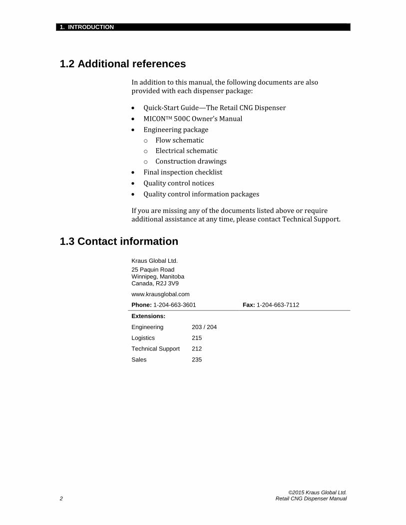
1.2 Additional references
In addition to this manual, the following documents are also provided with each dispenser package:
Quick-Start Guide—The Retail CNG Dispenser
MICONTM 500C Owner’s Manual
Engineering package
o Flow schematic
o Electrical schematic
o Construction drawings
Final inspection checklist
Quality control notices
Quality control information packages
If you are missing any of the documents listed above or require additional assistance at any time, please contact Technical Support.
1.3 Contact information
Kraus Global Ltd.
25 Paquin Road Winnipeg, Manitoba Canada, R2J 3V9
www.krausglobal.com
Phone: 1-204-663-3601 Fax: 1-204-663-7112
Extensions:
Engineering 203 / 204
Logistics 215
Technical Support 212
Sales 235

1. INTRODUCTION
©2015 Kraus Global Ltd. Retail CNG Dispenser Manual 3
1.4 Warnings and notifications
The following indicators provide various warnings and notifications throughout this manual:
ADVICE
This indicator provides helpful tips and other advice on proper equipment installation, usage, and maintenance.
ATTENTION
This indicator provides important notifications about the dispenser and its components.
CAUTION
This indicator provides critical warnings that may help prevent human injury and equipment damage.
1.5 Warranty information
For questions or concerns regarding dispenser-warranty policies, please contact Sales.

1. INTRODUCTION
©2015 Kraus Global Ltd. 4 Retail CNG Dispenser Manual
1.6 The Retail CNG dispenser
The Retail CNG dispenser is available in a single or multiple-line configuration. Each configuration is available in standard, high or split-flow systems; P30, P36, or split-pressure; single or dual hose setup; and buffer or cascade sequencing.
Additionally, the Retail CNG dispenser incorporates an industry-leading retail design that includes an embedded card reader, keypad, receipt printer, and your choice of a monochrome or full-color display. Table 1 below describes these customizable features.
Table 1: Retail dispenser configurations
Dispenser model Retail CNG Dispenser
Storage system Buffer (1 large bank) or Cascade (up to 3 banks)
Filling system High-flow or Standard-flow or Split-flow
Filling pressure P30 or P36 or Split-pressure
Hose configuration Single or Dual
Screen display Monochrome or Full-color
1.7 Dispenser theory of operation
This section explains how Kraus’ MICONTM 500C pump-controller and KAF 402™ solenoid valves operate to control gas flow within CNG dispensers.
1.7.1 The MICONTM 500C
Kraus’ MICONTM 500C pump-controller is an inexpensive alternative to using PLC units for operating fuel dispensers. For CNG dispensers, the MICONTM takes readings from the mass flow meter, pressure transducer, and temperature probe to determine a final fill pressure that is based on a series of algorithms in accordance with the Ideal Gas Law, “PV = nRT”. The result is a controlled fill of a vehicle’s CNG tank to a safe maximum limit.
After the fueling nozzle is attached and a fill is authorized, the MICONTM opens all KAF 402™ solenoid valve(s) and dispenses CNG into the vehicle’s receptacle for four seconds. After the four seconds, the MICONTM closes the valve(s) and performs a reading of the vehicle tank pressure and ambient temperature. Based on a combination of the initial reading and Ideal Gas Law calculations, the MICONTM determines a target-fill-pressure.

1. INTRODUCTION
©2015 Kraus Global Ltd. Retail CNG Dispenser Manual 5
1.7.2 Buffer storage systems
A buffer storage system comprises a large storage bank with a single supply line to the dispenser, which is controlled by one KAF 402™ solenoid valve to start and stop gas flow.
After the target-fill-pressure is calculated, the solenoid valve remains open for fuel delivery until the target-fill-pressure or minimum flow setting is reached.
1.7.3 Cascade storage systems
Cascade storage systems typically consist of three separate storage banks—a low, mid, and high bank. The low bank holds approximately 70% of the total volume of storage, while the mid and high banks hold 20% and 10% respectively.
Upon authorization, the MICONTM will open all three banks for 4 seconds to ensure there is sufficient gas flow to continue with the fill. The banks will then close for another 4 seconds for the target-fill calculation. Once the target-fill-pressure is calculated, the low-bank will reopen and deliver fuel until the flow rate drops to a predetermined level—set in the MICONTM. When this level is reached, the mid-bank solenoid valve will reopen to deliver the fuel. If more pressure is needed, the same sequence will occur to access the high-bank until the target-fill-pressure or minimum flow setting is reached.

1. INTRODUCTION
©2015 Kraus Global Ltd. 6 Retail CNG Dispenser Manual
1.7.4 The Retail unit layout
A single-hose Retail CNG dispenser—Please refer to the Engineering package for a view of internal components

2. SAFETY
©2015 Kraus Global Ltd. Retail CNG Dispenser Manual 7
2. SAFETY
CAUTION
Compressed Natural Gas (CNG) can pose great danger if mishandled. Please be sure to read and understand this section before installing, operating, or maintaining CNG dispensers.
ADVICE
It is necessary to comply with all safety precautions and other instructions described throughout this manual to properly install, operate, and maintain Kraus-manufactured CNG dispensers.
2.1 General safety
Where it is applicable, local regulations take precedence over the guidelines listed in this section. Please ensure that all personnel are familiar with all applicable regulations and observe the following guidelines when working with fuel dispensers:
Do not smoke or allow open flames and naked lights within 15 feet or 5 meters of any gas installation.
Do not adjust, remove, or bypass any protective devices.
Electrical equipment and its protection must comply with the regulations applicable to the hazard of the location.
Transportation, installation, commissioning, operation, maintenance, and repairs should only be carried out by qualified personnel in accordance with the regulations for operation and safety.
Electrical connections must comply with applicable local regulations.
Piping and other components, which are not supplied by Kraus Global Ltd., must be suitable for the respective working pressure. If necessary, they must be tested and protected by pressure-unloading devices.
Systems must be entirely vented before any maintenance or repair procedures are carried out.
Do not store flammable materials, such as oily rags, in or around the dispensing unit.

2. SAFETY
©2015 Kraus Global Ltd. 8 Retail CNG Dispenser Manual
2.2 Filling safety
Please observe the following guidelines when overseeing the use of all Kraus-CNG dispensers:
Be aware of emergency procedures and emergency telephone numbers.
Be aware of the locations of fire extinguishers and the “Emergency Shut Down” (ESD) buttons.
Ensure all operators and users are properly trained before any fueling transactions.
Do not allow any vehicles to be unattended while fueling.
Ensure that all automatic transmission vehicles are placed in “park” or the emergency brake is applied for all manual transmission vehicles before allowing any fueling transactions.
Ensure that all vehicle ignitions, electrical systems, and radios—including short-wave communication equipment—are shut-off before allowing any fueling transactions.
Ensure the fuel receptacle is inspected and matches the dispenser filling nozzle before attempting any fueling transactions.
Ensure all users adhere to the operating procedures described in Section 4.1 when fueling.
Ensure all users are aware that pressure from the nozzle must be vented before disengaging it from the vehicle.
Ensure that all users replace the dispenser nozzle firmly onto the holster immediately after refueling.
2. SAFETY
©2015 Kraus Global Ltd. Retail CNG Dispenser Manual 9
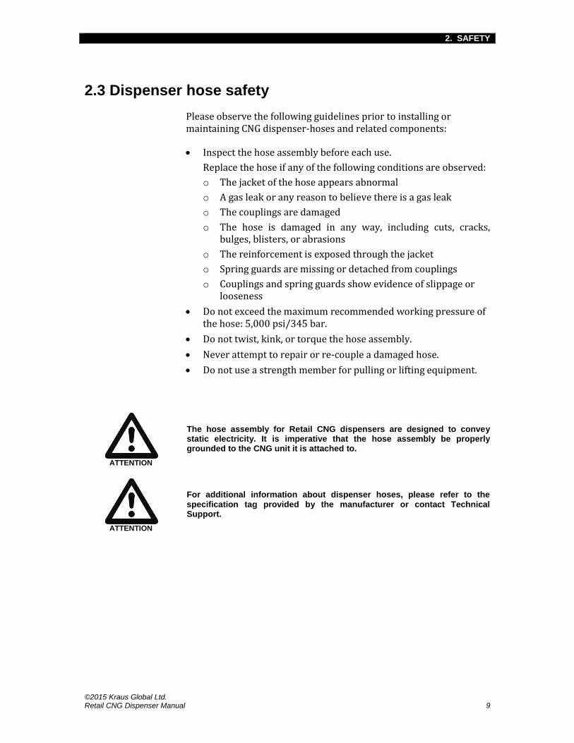
2.3 Dispenser hose safety
Please observe the following guidelines prior to installing or maintaining CNG dispenser-hoses and related components:
Inspect the hose assembly before each use.
Replace the hose if any of the following conditions are observed:
o The jacket of the hose appears abnormal
o A gas leak or any reason to believe there is a gas leak
o The couplings are damaged
o The hose is damaged in any way, including cuts, cracks, bulges, blisters, or abrasions
o The reinforcement is exposed through the jacket
o Spring guards are missing or detached from couplings
o Couplings and spring guards show evidence of slippage or looseness
Do not exceed the maximum recommended working pressure of the hose: 5,000 psi/345 bar.
Do not twist, kink, or torque the hose assembly.
Never attempt to repair or re-couple a damaged hose.
Do not use a strength member for pulling or lifting equipment.
ATTENTION
The hose assembly for Retail CNG dispensers are designed to convey static electricity. It is imperative that the hose assembly be properly grounded to the CNG unit it is attached to.
ATTENTION
For additional information about dispenser hoses, please refer to the specification tag provided by the manufacturer or contact Technical Support.

2. SAFETY
©2015 Kraus Global Ltd. 10 Retail CNG Dispenser Manual
2.4 Maintenance safety
Please observe the following guidelines prior to maintaining any Kraus CNG dispenser:
Only properly trained or qualified personnel should be permitted to maintain and repair CNG equipment. When in doubt, please refer to the equipment supplier or service agent.
Always adhere to the manufacturer guidelines for proper installation and maintenance of all dispensers and dispenser-components.
All maintenance and repair work of pressure vessels and other safety equipment must be conducted under the appropriate codes, then tested and accepted by the inspection authority.
The dispenser must be powered-off and completely vented, unless otherwise specified.
Never perform welding processes near gas systems.
Always cover disassembled parts and openings with a clean rag, paper, or adhesive to keep them clean and avoid contamination.
Do not clean any parts with flammable solvent. Clean and rinse all parts carefully with compressed air.
Be sure to wear necessary safety equipment during maintenance and repair. Eye protection is absolutely necessary when cleaning with compressed air.
Wear hearing, hand, and eye protection when bleeding filters and lines. Be sure to keep body parts away from the discharge orifice.
Do not touch bare wires and live current-carrying parts while the electrical system is energized.
Never tighten or loosen any fitting when it is under pressure.
Always use proper thread lubricants and sealant on tapered pipe threads.
Never turn a fitting body. Instead, hold fitting body and turn the nut.
After completing any work on process gas piping systems and its components, always purge the system thoroughly with a non-corrosive inert gas, such as nitrogen, before introducing natural gas.
Ensure that you have not left any tools, cleaning equipment, or any loose parts inside the dispenser.
ADVICE
Never allow problems to go unreported. Both your company and supplier will benefit from the full disclosure of all dispenser issues.

2. SAFETY
©2015 Kraus Global Ltd. Retail CNG Dispenser Manual 11
2.5 Leak test safety
Please observe the following guidelines before performing leak tests on Kraus-manufactured CNG dispensers:
Ensure the area surrounding the dispenser being serviced is closed off to all customers and unauthorized personnel. Use any appropriate barricade and signage to ensure safety.
It is recommended that protective shields be placed around potentially harmful areas of the dispenser being serviced.
Service personnel must wear all appropriate safety gear, such as helmets with eye and/or facial protection and body shields.

3. INSTALLATION AND SETUP
©2015 Kraus Global Ltd. 12 Retail CNG Dispenser Manual
3. INSTALLATION AND SETUP
3.1 Installation guidelines
Please observe the following guidelines prior to installing any Kraus-manufactured CNG dispenser:
All electrical and mechanical installations must comply with the provisions of the local authority having jurisdiction.
All electrical installations must only be carried out by a licensed electrical journeyman.
All high-pressure gas connections should only be carried out by qualified and experienced personnel.
Safety valve discharge gases must be funneled safely away from the working area using tubing or piping with comparable pressure ratings to the tubing or piping used within the dispenser.
Be sure to allow room inside the dispenser pit to properly tie-in the gas lines to the inline filters and manual isolation valves.
Where soil displacement is apparent, gas connections upstream of the dispenser must be made with flexible hoses.
The dispenser frame enclosure must be securely bolted to a concrete foundation or to a structural steel base. Adequate support must be provided for each unit of the dispensing system, independent of piping, tubing, or conduit that may be connected to the dispenser.
A pressure relief device may be installed directly upstream of the dispenser—in compliance with the ASME Boiler and Pressure Vessel Code—to limit the pressure at the inlet of the dispenser to a value no greater than the maximum working pressure of the dispenser.
o The pressure relief device must communicate directly with the pressure-containing component it is designed to protect—valves between the protected component and the inlet to the pressure relief device are not permitted.
All dispensers must be equipped with an emergency shut-off device that will terminate the gas supply to the dispenser in the event that the dispenser is upset or sheared from its foundation for any reason.
All dispensers must only be used for gas compositions specified within SAE J1616: Recommended Practice for Compressed Natural Gas Vehicle.

3. INSTALLATION AND SETUP
©2015 Kraus Global Ltd. Retail CNG Dispenser Manual 13
3.2 Pre-installation
CAUTION
Kraus CNG dispensers must be situated in such a way that there are no obstructions, such as a wall or gate, that may entangle the dispenser hose. This is to ensure proper functioning of the hose assembly’s breakaway coupling.
3.2.1 Site preparation
Please observe the following guidelines prior to constructing dispenser pits:
Be sure to allow room inside the dispenser pit to properly tie-in the gas lines to the inlet filters and manual isolation valves.
Make provisions for tubing and electrical conduits prior to pouring the concrete pad.
Filters must be installed upstream of the dispenser.
Due to potential weld slag, filings, rust, dirt, and water, dispensing lines should be purged to the atmosphere at the dispenser. This can be done by blowing nitrogen through the lines.
All dispensing lines must be purged, pressurized, and leak tested. Afterwards, manual isolating valves in the dispenser pit must also be leak tested. The dispenser must only be connected to the lines after these have been accomplished.
ATTENTION
Please refer to your Construction drawings for dispenser dimensions.

3. INSTALLATION AND SETUP
©2015 Kraus Global Ltd. 14 Retail CNG Dispenser Manual
3.2.2 Uncrating the dispenser
CAUTION
Ensure that the dispenser crate is placed on a smooth and level surface before removing any crate panels.
ATTENTION
All dispenser packages contain additional parts, accessories, and documents that are vital to the installation, operation, and maintenance of the dispenser. Be sure to set these items aside in a safe and easily accessible area.
Dispenser keys may be found on one of the authorization handles.
1. Inspect the crate for any damages that may have occurred during shipping. If any damages are found:
o Take pictures of the damages
o Note the damages
o Contact Kraus
2. Starting with the top panel, remove all screws and/or nails and detach the top panel. Repeat this process to remove all side panels.
3. Remove all protective wrapping by hand; knives and other sharp objects may damage the dispenser.
4. Inspect the dispenser for any damages. If any damages are found, repeat the procedure indicated in step 1.
5. Remove lag bolts from base rails to free the dispenser from the bottom pallet.
6. Locate and review the crating check list to ensure that all items are accounted for. If you are missing any items, please contact Technical Support.

3. INSTALLATION AND SETUP
©2015 Kraus Global Ltd. Retail CNG Dispenser Manual 15
3.2.3 Lifting and anchoring the dispenser
CAUTION
Kraus CNG dispensers weigh at least 1,200 lbs/545 kg; be sure all lifting and anchoring equipment are suitable for the weight.
1. Locate the lifting lugs on top of the dispenser. A step-stool or step-ladder may be required to get a full view.
2. Attach lifting straps to the lifting lugs using clevises.
3. Hoist the dispenser off the pallet with a suitable forklift or crane and carefully move the dispenser over the dispenser pit.
4. Ensure the area directly below the dispenser is free of electrical wires, tubing, and other obstacles.
5. Lower the dispenser slowly into the pit.
6. Fasten the dispenser to the pit frame or concrete base with—at the minimum—½” NC, grade 8 steel bolts.
ADVICE
Ensure there is sufficient room to complete tubing and wiring connections before securing the dispenser to the foundation.
ATTENTION
The supply ground cable must be securely connected to the dispenser frame.

3. INSTALLATION AND SETUP
©2015 Kraus Global Ltd. 16 Retail CNG Dispenser Manual
3.3 Installation
3.3.1 Electrical and communication connections
CAUTION
Electrical installations must only be carried out by licensed electrical journeymen.
ATTENTION
All interconnection tubings and fittings are sold independently of Kraus Global Ltd.
Always adhere to manufacturer standards for appropriate swaging and tightening specifications.
Electrical
The dispenser’s main electrical connections are done at the terminal strip, located in the explosion-proof junction box in the lower cabinet of the dispenser. An electrical conduit, labeled “ELECTRICAL,” is provided to allow optimum protection and direct routing to the explosion-proof junction box.
Please refer to the electrical schematic within the Engineering package for electrical connection specifications.
Communication
An electrical conduit, labeled “COMMUNICATION,” is provided in the lower cabinet for all communication wiring. This conduit allows direct routing to the upper cabinet where the CRINDTM and pump connections are made.
Please refer to the electrical schematic within the Engineering package for communication connection specifications.
3.3.2 Pressure line connection
CAUTION
High-pressure gas connections must only be carried out by qualified and experienced personnel.
Please refer to the flow schematic within the Engineering package for pressure line connection specifications.

3. INSTALLATION AND SETUP
©2015 Kraus Global Ltd. Retail CNG Dispenser Manual 17
3.3.3 Filters
CNG may be filtered in one of two methods:
Particulate filtration removes solid particles from gases; ensuring only clean gas is dispensed into a vehicle.
Coalescing filtration removes solid particles with the same efficiency as particulate filtration, but also removes water aerosols and droplets from gases; ensuring only clean and dry gas is dispensed into a vehicle. This is the standard and recommended method of filtration for all Kraus CNG dispensers.
Filter size and placement
Filter sizes and their placement depend on the configuration of the dispenser. High-flow dispensers require large filters that may be placed in one of the following locations:
In the dispenser pit if it is large enough to house the filters, while providing enough room to drain and change filter elements
Upstream of the dispenser pit, on the dispenser supply lines between the priority panel and the dispenser
See Figure 1 below for high-flow filter placement options.
Standard-flow dispensers use smaller filters that can often be placed in the lower cabinet of the dispenser unless otherwise indicated.
ATTENTION
If filters are not being supplied by Kraus Global Ltd., ensure that they are properly rated for the dispenser’s filling system.
You may contact Technical Support for any questions regarding dispenser configurations.
Figure 1: High-flow filter placement

3. INSTALLATION AND SETUP
©2015 Kraus Global Ltd. 18 Retail CNG Dispenser Manual
Filter installation guidelines
ATTENTION
Filter housings are pressure vessels and must only be used within their allowable working pressure, within their stated temperature range.
As pressure vessels, filter housings must be leak-tight. It is considered good practice to use pipe sealants on fittings prior to connecting the filter housing ports.
Ensure the filters are visible and easily accessible for periodic draining and maintenance.
Install the filters on a level pipeline and mount vertically. Be sure to leave one bowl length of clearance to allow for element removal.
Ensure that fittings are always inspected during servicing and adjusted accordingly.
Avoid swapping the heads and bowls of one filter assembly to another.

3. INSTALLATION AND SETUP
©2015 Kraus Global Ltd. Retail CNG Dispenser Manual 19
3.3.4 Attaching the hose
Kraus CNG dispensers use Parker brand hoses and hose fittings. Hose sizes are specific to dispenser configurations, but are available in various lengths. Please see the information sheet attached to the hose package or contact Technical Support for further specification.
Please be sure to read and understand Section 2.3—Dispenser hose safety before proceeding.
CAUTION
If your hose is unusable or if you have any reason to believe it may be unusable, please contact Technical Support immediately.
Do not use defective or damaged hoses.
ATTENTION
If you are operating a split-pressure or split-flow dispenser, ensure that you attach the correct hose to the proper connection.
1. Remove the hose from its packaging.
2. Inspect the hose for any defects or damages that may have occurred during shipment.
NOTE: Never use defective or damaged hoses. If a defect or any damage is found, contact Technical Support immediately.
3. Attach the main line to the hose manifold, located on the side; along the top of the dispenser. Hose manifolds may be on both sides, depending on the dispenser’s hose configuration.
4. Hand-tighten the main line fitting to the manifold so it will still be loose enough to turn.
5. Straighten the hose and place the nozzle into the holder. The loose fitting should allow the hose to find its natural resting position.
6. Tighten the main line fitting at the manifold with a backup wrench. Hose connections do not require sealants or Teflon tape.
7. Attach the vent line to the corresponding manifold connection and tighten with a backup wrench.
CAUTION
To help avoid abrasive damage to the hoses, do not allow any part of the hose to be in contact with the ground or dispenser while it is holstered. If this is the case, the hose may be too long; please contact our Technical Support Department immediately.

3. INSTALLATION AND SETUP
©2015 Kraus Global Ltd. 20 Retail CNG Dispenser Manual
Breakaway couplings
All Kraus CNG dispenser hoses are equipped with a breakaway safety feature. Breakaway couplings are in place to prevent the flow of natural gas should a vehicle drive away from a dispenser while the nozzle and hose are still connected to the vehicle’s receptacle.
CAUTION
If a breakaway occurs, the entire hose assembly must be examined by a qualified service representative prior to any reconnections.
ATTENTION
In the event of a breakaway, dispenser hose assemblies may only be reconnected if the breakaway was clean; otherwise, the assembly will have to be rebuilt using the breakaway rebuild kit or completely replaced with new parts and fittings. Please consult our Technical Support Department before proceeding with either option.
Reconnecting procedure
1. Vent the dispenser system and hose assembly before attempting any reconnections. Please refer to Section 4.2—Maintenance for dispenser-venting procedures.
2. Clean dirt, debris, and other obstructions from both sides of the breakaway unit.
3. Inspect both parts of the breakaway unit. Ensure that O-ring seals are not damaged.
NOTE: Never reconnect assemblies if any components are damaged.
4. Inspect the stationary module and ensure that the inner garter spring is intact and properly situated in the groove.
5. Insert the breakaway unit into the stationary module by aligning the wrench flats of the unit with the lining of the module.
6. Push the breakaway unit into the stationary module until you feel a click.
7. Perform a leak test to ensure the system and hose assembly are in working condition. Please refer to Section 4.2—Maintenance for leak-testing procedures.
ATTENTION
Breakaway couplings may require a specialized reconnection tool—contact Technical Support information.

3. INSTALLATION AND SETUP
©2015 Kraus Global Ltd. Retail CNG Dispenser Manual 21
3.4 Startup procedures
3.4.1 Powering the dispenser
The following steps are guidelines for powering-up the dispenser, assuming all electrical and mechanical connections have been properly installed. Please be sure to read and understand Chapter 2—Safety before proceeding.
ATTENTION
The dispenser is shipped in “Standalone mode.” It is recommended that the initial power-up process is done under this mode to facilitate procedures requiring authorization.
1. Remove the bottom panels of the dispenser to access the lower cabinet.
2. Close all manual filter inlet valves, vent valves, and manual shut-off valves.
3. Inspect the Magnehelic gauge; ensure the air pressure is above 0.15 inches-of-water.
ATTENTION
For safety purposes, the upper cabinet must maintain a positive air pressure. A purge switch and timer are used to trigger automatic system-shutdowns and startups. If the Magnehelic gauge displays a pressure lower than 0.15, dispenser electronics may not function. You may need to increase the purge fan pressure or inspect the cabinet and air purge system for leaks.
4. Turn on the power to the dispenser from the breaker box.
NOTE: The dispenser-electronics, CRINDTM, and MICONTM will simultaneously initiate the following power-up sequences:
o The dispenser-display will show the current software version and dispenser model throughout this sequence. The power-up sequence is complete when the dollar and volume
displays respectively read 0.00 and 0.000.
o The CRINDTM-display will show the Gilbarco Veeder-Root logo. The power-up sequence is complete when the display reads: Encore® 500/Eclipse CRINDTM—Please Program CRINDTM
Mode.
o The digital pressure gauge, located on the left side of the dispenser, will count down from 25. The power-up sequence

3. INSTALLATION AND SETUP
©2015 Kraus Global Ltd. 22 Retail CNG Dispenser Manual
is complete when the countdown reaches zero and the
display reads 0000.
Encore® is a registered trademark of Gilbarco Veeder-Root.

3. INSTALLATION AND SETUP
©2015 Kraus Global Ltd. Retail CNG Dispenser Manual 23
3.4.2 Pressurizing the dispenser
The following steps are guidelines for pressurizing the dispenser; the dispenser must be powered-on for this procedure. Please be sure to read and understand Chapter 2—Safety before proceeding.
ADVICE
To ensure peak performance, all Kraus CNG dispensers should be leak-tested before initial operation. The first leak test should be done while initially pressurizing the dispenser.
ATTENTION
If your dispenser operates over a cascade storage system, complete the following procedure with the low-bank first, the mid-bank second, and the high-bank last.
1. Open the manual shut-off valve(s), located along the side(s) of the dispenser.
2. Flip the authorization handle to the ON position.
3. Slowly open the inlet valve and allow 100 psi of gas to fill the dispenser.
NOTE: Pressure may be monitored through the digital pressure gauge or the mechanical gauge attached to the sensor vent manifold.
4. Close the inlet valve and flip the authorization handle to the OFF position once the pressure gauge indicates 100 psi.
5. Apply a leak detector to all fitting connections—we recommend using Snoop® Liquid Detector.
NOTE: If any leaks are detected, please refer to Section 4.2—Maintenance for leak repair procedures.
6. If no leaks are found, reauthorize the dispenser by flipping the authorization handle up to the ON position.
7. Slowly reopen the valve to allow 500 psi of gas to fill the dispenser.
8. Close the valve once the pressure gauge indicates 500 psi.
9. Reapply the leak detector. See the previous Note if leaks are detected.
10. Repeat this process at 500 psi increments until the regular operating pressure is reached. Repeat the process for each inlet valve.

3. INSTALLATION AND SETUP
©2015 Kraus Global Ltd. 24 Retail CNG Dispenser Manual
3.4.3 Connecting the Manager-keypad
The Manager-keypad is a flat magnetic keypad connected to a ribbon cable. It allows personnel to configure the dispenser-electronics and CRINDTM parameters; it may be found attached to the inside wall of the upper cabinet. The following steps are guidelines for connecting the keypad to the pump door node.
1. Turn off the power to the dispenser from the breaker box.
2. Open the upper cabinet. You may need the dispenser keys to unlock the cabinet door.
3. Retrieve the Manager-keypad from inside the upper cabinet.
4. Connect the keypad to the pin connector labeled “MANAGER KEYPAD” on the pump door node, located directly behind the dispenser-display. The arrow in Figure 2 points to the position of the pin connector on the door node.
Figure 2: Manager-keypad pin connector on pump door node
Figure 3: Keypad position at start up
5. Hang the keypad over the cabinet door. This allows the cabinet door to close, while allowing use of the keypad; see Figure 3.
6. Ensure the cabinet door is closed and fully sealed.
NOTE: Dispenser-electronics will not function if the upper cabinet is not sufficiently pressurized.
7. Turn on the power to the dispenser at the breaker box.
NOTE: The keypad is now ready for use; you may need to allow all power-up sequences to complete before proceeding.

3. INSTALLATION AND SETUP
©2015 Kraus Global Ltd. Retail CNG Dispenser Manual 25
3.4.4 Enabling 2-wire mode and setting pump/hose IDs
“2-wire mode” is a fill-authorization option that requires customers to complete a payment transaction before a fill may be authorized. By enabling “2-wire mode,” you are disabling “Standalone mode.”
Preliminary steps
1. Press F1 on the Manager-keypad to enter Programming mode.
NOTE: The dispenser-display will flash 8888.
2. Enter the level 2 security code: 1503.
3. Press Enter.
NOTE: The dispenser-display will flash 0000 after the code is
accepted.
Enabling “2-wire mode”
1. Enter command code: 24.
2. Press Enter.
3. Enter 1 to choose 2-wire mode.
NOTE: 1 = 2-wire mode
2 = Standalone mode
4. Press Enter.
5. Press F1 to choose another command code (see Setting pump/hose IDs on the following page).
2-wire system lockout
After enabling “2-wire mode,” a system-lockout is engaged, preventing any further modification of this option. To revert to “Standalone mode,” follow the procedure below:
1. Shut-off the power from the breaker box.
2. Manually disconnect the 2-wire connection in the upper cabinet.
3. Restore power from the breaker box.
4. Allow the dispenser to fully reboot and complete all power-up sequences.
5. Allow the dispenser to sit idle for 6 full minutes (after rebooting).
6. Follow the procedures above to re-enter Programming mode and reselect “Standalone mode”.

3. INSTALLATION AND SETUP
©2015 Kraus Global Ltd. 26 Retail CNG Dispenser Manual
Setting pump/hose IDs
1. Enter command code: 40.
2. Press Enter.
NOTE: The dispenser-display will show three numbers to the right of the command code. The first flashing number represents the dispenser side (either 1 or 2); the two flashing numbers that follow represent the hose number (01, 02, 03, etc.).
3. Enter 1 to set a hose number for side 1.
4. Press Enter.
5. Enter the 2-digit hose number designated to side 1.
6. Press Enter.
ATTENTION
There are 4 jumper-pins along the top-right corner of each pump door node. If the pin labeled “A0” is covered with a jumper, it is dispenser side 2.
7. Enter 2 to set a hose number for side 2.
8. Press Enter.
9. Enter the 2-digit hose number designated to side 2.
10. Press Enter.
11. Press F2 to save the current settings and exit Programming mode.
NOTE: Dispenser-electronics will reboot as your settings are applied.
3. INSTALLATION AND SETUP
©2015 Kraus Global Ltd. Retail CNG Dispenser Manual 27
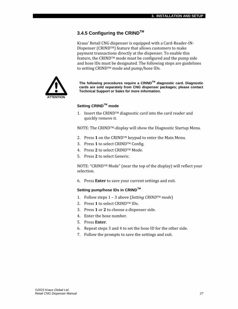
3.4.5 Configuring the CRINDTM
Kraus’ Retail CNG dispenser is equipped with a Card-Reader-IN-Dispenser (CRINDTM) feature that allows customers to make payment transactions directly at the dispenser. To enable this feature, the CRINDTM mode must be configured and the pump side and hose IDs must be designated. The following steps are guidelines to setting CRINDTM mode and pump/hose IDs.
ATTENTION
The following procedures require a CRINDTM
diagnostic card. Diagnostic cards are sold separately from CNG dispenser packages; please contact Technical Support or Sales for more information.
Setting CRINDTM
mode
1. Insert the CRINDTM diagnostic card into the card reader and quickly remove it.
NOTE: The CRINDTM-display will show the Diagnostic Startup Menu.
2. Press 1 on the CRINDTM keypad to enter the Main Menu.
3. Press 1 to select CRINDTM Config.
4. Press 2 to select CRINDTM Mode.
5. Press 2 to select Generic.
NOTE: “CRINDTM Mode” (near the top of the display) will reflect your selection.
6. Press Enter to save your current settings and exit.
Setting pump/hose IDs in CRINDTM
1. Follow steps 1 – 3 above (Setting CRINDTM mode)
2. Press 1 to select CRINDTM IDs.
3. Press 1 or 2 to choose a dispenser side.
4. Enter the hose number.
5. Press Enter.
6. Repeat steps 3 and 4 to set the hose ID for the other side.
7. Follow the prompts to save the settings and exit.

3. INSTALLATION AND SETUP
©2015 Kraus Global Ltd. 28 Retail CNG Dispenser Manual
3.4.6 Commissioning
Commissioning is necessary to ensure all dispenser systems, including all components, are installed and function properly, and are successfully turned over. Documenting the commissioning process allows for traceable verification and ensures a systematic approach to minimizing any commissioning oversights.
A commissioning sign-off sheet is included within your dispenser package. This form must be completed, signed, and sent to Kraus Global Ltd. within 30 days of commissioning, otherwise the warranty may be voided.
Complete forms may be mailed or faxed to Kraus Global Ltd. using the following information:
Kraus Global Ltd. 25 Paquin Road Winnipeg, MB Canada, R2J 3V9
Fax: 1-204-663-7112

4. OPERATION AND MAINTENANCE
©2015 Kraus Global Ltd. Retail CNG Dispenser Manual 29
4. OPERATION AND MAINTENANCE
4.1 Filling procedure
The following is the procedure for filling CNG approved vehicles with the Retail CNG dispenser. Ensure all users observe the guidelines described in Section 2.2 and adhere to this procedure when fueling.
ADVICE
Ensure all personnel, including users, are aware of emergency shut-down buttons prior to operating CNG fuel dispensers.
1. Ensure the vehicle is in “park” or the parking brake is applied, and the vehicle ignition is turned OFF.
2. Inspect the vehicle’s receptacle and the dispenser hose and nozzle. Do not proceed with fueling or allow further use of the dispenser if any damages or signs of tampering are found; you may contact our Technical Support Department for further assistance: 1-204-663-3601 (ext. 212).
3. Remove the dust plug from the vehicle’s CNG receptacle.
4. Lift the refueling nozzle from the holder.
5. Connect the refueling nozzle to the vehicle receptacle.
6. Follow the prompts on the CRINDTM-display; you may be required to complete a payment transaction before a fill can be authorized.
7. Turn the valve on the nozzle to FILL.
8. Flip the authorization handle up to the ON position; fueling will begin after a three-second beep.
ATTENTION
Note the following during gas delivery:
Gas delivery may create a loud whining sound. This is due to the pressure differential between the dispenser and the vehicle’s storage bank. This is normal and is not a cause for concern.
There may be noticeable pauses as the dispenser accesses multiple storage banks; delivery is not complete until the dispenser beeps for three full seconds.
9. Flip the authorization handle back down at the end of delivery; a three-second beep will signify the end of delivery.
10. Turn the valve on the nozzle to VENT. This will vent a small amount of gas into the atmosphere and allow you to disconnect the nozzle.
11. Replace the nozzle onto the holder.
12. Replace the dust plug into the vehicle’s CNG receptacle.

4. OPERATION AND MAINTENANCE
©2015 Kraus Global Ltd. 30 Retail CNG Dispenser Manual
4.2 Programming the MICONTM
In order to program specific MICONTM parameters, an Info-Pac is required and the MICONTM must be placed in “programming mode” to be able to transmit and receive signals.
4.2.1 The Info-Pac
An Info-Pac is a self-contained, battery-powered handheld transceiver designed to program and monitor the MICONTM 500C pump-controllers used in CNG applications.
ATTENTION
Info-Pacs are sold separately from all dispenser packages. Please contact Technical Support or Sales for questions and ordering information.
4.2.2 Enabling Programming mode
1. Ensure the AC power is OFF.
2. Attach the MICONTM battery to the battery harness connected to the MICONTM head; it is labeled “BATTERY.”
NOTE: A MICONTM battery is included in all dispenser packages. Please contact our Technical Support Department if the battery cannot be found.
3. Flip the MICONTM switch towards you; the switch is located above the MICONTM cabinet.
The MICONTM is now ready for Info-Pac use. Please refer to the Info-Pac Programming Manual for step-by-step programming procedures.
4.2.3 Disabling Programming mode
1. Flip the MICONTM switch away from you; the switch is located above the MICONTM cabinet.
2. Disconnect the MICONTM battery and store it in a safe place.
3. Restore AC power to the dispenser.
CAUTION
To avoid undesired electric arcing, DO NOT store the MICONTM
battery in dispenser cabinets.

4. OPERATION AND MAINTENANCE
©2015 Kraus Global Ltd. Retail CNG Dispenser Manual 31
4.3 Dispenser maintenance
CAUTION
Please read and understand Section 2.4—Maintenance safety before performing any maintenance on fuel dispensers.
ADVICE
Be sure to note and report all dispenser issues. It is considered good practice to use a maintenance log sheet to document all dispenser issues and repairs.
4.3.1 General dispenser maintenance guidelines
Please refer to the Maintenance task list in the Appendix, for a detailed maintenance schedule.
Shut off all manual isolation valves in the dispenser pit after hours and other times when the dispenser will not be in use.
Ensure that all valves, gauges, and displays are free of obstructions.
Clean the dispenser on a regular basis. Avoid using pressurized water.
Perform daily checks for signs of leakage.
Perform leak inspections of all hoses and fittings every six months with an approved leak detector fluid. Ensure that all leaks are repaired by qualified personnel immediately.
Perform monthly hose inspections. Check for abrasions, swelling, flatness, cuts, damaged couplings, and other abnormal signs. Replace the hose immediately if any abnormalities are found.
Depending on installation requirements, we recommend that inline filter elements are checked and replaced two weeks after initial installation.
Check filter elements every month and replace when necessary

4. OPERATION AND MAINTENANCE
©2015 Kraus Global Ltd. 32 Retail CNG Dispenser Manual
4.3.2 Dispenser venting procedure
The following steps are guidelines for venting the Retail CNG dispenser.
CAUTION
All CNG dispensers must be completely vented prior to performing any maintenance work, including leak-testing and repairs.
1. Isolate the dispenser by placing highly visible signs or physical barriers to prevent traffic in the immediate area.
2. Ensure the refueling nozzle is replaced in the holder.
3. Ensure there is power to the dispenser. The dispenser must be electrically functional to operate the inlet valves.
4. Ensure the manual shut-off valve(s) is/are open.
5. Close all manual filter inlet valves to terminate gas flow from the storage vessels to the dispenser.
6. Slowly loosen the vent valves at least 3 to 4 turns to vent the trapped gases in the dispenser.
NOTE: Read the pressure gauges to confirm the gas is being vented.
CAUTION
Do not touch any venting pipes throughout this procedure. Rapidly expanding gases may cause sub-zero temperature drops within the vent stacks, which may cause cold burns.
NOTE: At this point, only gases upstream of the sequencing valves, including gas inside the hoses, have been vented; there may still be gases trapped downstream of the sequencing valves down to the filter isolation valves.
7. Lift the authorization handle to authorize a fill. This will open the sequencing valves allow trapped gases to escape.
NOTE: Sequencing valves are only opened for 4 seconds at a time; you may need to authorize a fill several times to vent all trapped gases. Continue authorizing a fill until the pressure gauge reads 0 psi and all venting sounds have ceased.

4. OPERATION AND MAINTENANCE
©2015 Kraus Global Ltd. Retail CNG Dispenser Manual 33
4.3.3 Leak monitoring
Leaks in dispenser equipment may develop within the first few weeks of operation and, therefore, must be closely monitored throughout this time. Thereafter, routinely scheduled maintenance must be carried out to correct and prevent further leaks.
The following steps are guidelines for detecting and repairing leaks.
CAUTION
NEVER TIGHTEN, LOOSEN, OR ATTEMPT TO REMOVE A PRESSURIZED FITTING.
Leak-testing procedure
1. Remove the bottom panels of the dispenser to access the lower cabinet.
2. Apply a leak detector to all fitting connections—we recommend using Snoop® Liquid Leak Detector.
3. Thoroughly inspect all fitting connections for bubbles, which indicate a leak. Be sure to note or mark the locations where leaks are found.
4. If leaks are found, vent gas from the dispenser—see Dispenser-venting procedure—and proceed with repairing the leak.
CAUTION
If a leak appears downstream of a sequencing valve, you must authorize a fill to vent the trapped gas. Continue authorizing a fill until the pressure gauge reads 0 psi and all venting sounds have ceased.
Leak repairing procedure
1. Ensure the dispenser is completely vented.
2. Loosen and retighten the fittings where leaks are found; most fittings can be repaired simply by tightening it.
3. Pressurize the dispenser to 100 psi and reassess all fitting connections with a leak detector.
4. Continue pressurizing the dispenser and testing for leaks at 500 psi intervals until the dispenser reaches regular operating pressures.
NOTE: Repeat steps 1 – 3 if leaks are discovered. If leaks persist, contact our Technical Support Department.

©2015 Kraus Global Ltd. 34 Retail CNG Dispenser Manual
4.4 Component maintenance
This section provides guidelines and important notifications regarding the maintenance of vital dispenser components.
4.4.1 MICONTM mainboard
The following steps are guidelines for replacing the MICONTM mainboard.
ADVICE
Ensure the replacement mainboard has identical software parameter configurations as the previous mainboard.
1. Record current MICONTM parameters, as they may be reset upon installation of the new mainboard.
2. Shut-off the power to the dispenser from the breaker box.
3. Open the upper cabinet; you may require keys to unlock the cabinet door.
4. Remove the two screws securing the MICONTM cover.
5. Remove the MICONTM cover.
6. Remove the two screws securing the mainboard to the enclosure.
7. Disconnect all connectors and harnesses until the mainboard is free.
NOTE: Be sure to note or have an understanding of these connections, as they must all be reconnected to the replacement mainboard. You may refer to the Info-Pac Programming Manual for connector designation.
8. Install the replacement mainboard. Ensure that you have:
o Secured all previous mainboard connections
o Replaced both screws to secure the mainboard to the enclosure
o Replaced the MICONTM cover
o Replaced the two screws securing the MICONTM cover
9. Use the Info-Pac to reconfigure the MICONTM to your preferred parameters.
10. Restore power to the dispenser from the breaker box.

4. OPERATION AND MAINTENANCE
©2015 Kraus Global Ltd. Retail CNG Dispenser Manual 35
4.4.2 KAF 402™ solenoid inlet valve
Kraus’ KAF 402™ solenoid valve has been specifically engineered for high-pressure CNG service. It is constructed of materials suitable for use with natural gas and is rated for a burst pressure in excess of 25,000 psi.
To ensure the proper solenoid valve(s) are in proper working condition please observe the following maintenance guidelines:
The valve(s) must be leak-tested after every 35,000 cycles or every six months, whichever comes first.
The valve(s) must be rebuilt at least once every three years by qualified service personnel and in accordance with the rebuild procedure described in the KAF 402™ rebuilding specification sheet.
ATTENTION
Rebuild kits are required to properly rebuild KAF 402™ solenoid valves for any maintenance or reparation purposes. They are sold separately from any dispenser systems; please contact our sales or technical support department for any questions.
4.4.3 Inlet filters
CNG filtering is a balanced, continuous, and steady state condition occurring at or below rated flow. In order to maintain high-efficiency filtration for your CNG dispenser, ensure that the bowl is kept clean and free of waste build-up.
Filter element replacement procedure
1. Ensure the dispenser is completely vented.
2. Open the filter drain valve to ensure all pressure has been vented.
3. Unthread and remove the bowl—set it aside in a secure location.
4. Remove and discard clogged filter element and O-ring.
5. Install new element.
6. Install new O-ring. Lightly lubricate the new O-ring using a clear silicon-based grease.
7. Apply a thin layer of anti-seize onto the filter bowl threads.
8. Thread the filter bowl to the head, making sure not to pinch O-ring.

4. OPERATION AND MAINTENANCE
©2015 Kraus Global Ltd. 36 Retail CNG Dispenser Manual
4.4.4 Air purge system
Kraus’ Retail CNG dispensers incorporate an air purge system to ensure the open electronics in the upper cabinet are protected from potential gas leaks that may cause explosion. The air purge system uses a purge fan to maintain a positive air pressure of at least 0.15 inches-of-water in the upper cabinet; otherwise the dispenser system is automatically shutdown. A Magnehelic gauge, located in the lower cabinet is used to monitor this pressure.
Purge fan filter maintenance guidelines
Inspect and clean the purge fan filter once-a-month.
To clean, rinse the filter with soap and water.
Dry thoroughly before reinstalling filter.

5. TROUBLESHOOTING
©2015 Kraus Global Ltd. Retail CNG Dispenser Manual 37
5. TROUBLESHOOTING
5.1 MICONTM
fault codes
In the event of a MICONTM -related malfunction, the Retail dispenser will display an error code in the filling pressure-display. This section provides a description of MICONTM error codes and possible solutions to remedy the errors.
Table 2 provides a summary of all MICONTM fault codes, possible causes, and recommended actions for addressing the errors.
Table 3 provides a list of procedures for clearing MICONTM error code messages from the filling-pressure display.
ADVICE
Please contact our Technical Support Department at 1-204-663-3601 for any issues not covered in the table below.
Table 2: MICONTM fault code summaries
ERROR CODE
DESCRIPTION POSSIBLE CAUSE RECOMMENDED ACTION
co26 Pulser fault Pulser is missing or disconnected
Not applicable when using CNG050 mass flow meter
If fault occurs, use the MICONTM
Info-Pac to set “Pulser” option to conduit-s
co27 Pulser buffer overflow fault
Input pulses coming in may be faster than what the MICON
TM
500C is rated to handle
Ensure the MICONTM
in count and multiplier values are set to factory settings
Ensure that mass flow meter frequency and rate factors are set to factory settings
co28 Display disconnect fault
LCD display lost connection
Check all display harness connections between display and MICON
TM mainboard
If all connections are good, replace LCD display
co29 CPU fault Corrupt CPU Perform cold start on MICONTM
500C
Replace CPU chip
co30 Excessive reverse count fault
Pulser is connected backwards
Not applicable when using CNG050 mass flow meter

5. TROUBLESHOOTING
©2015 Kraus Global Ltd. 38 Retail CNG Dispenser Manual
Table 2: MICONTM fault code summaries (continued)
ERROR CODE
DESCRIPTION POSSIBLE CAUSE RECOMMENDED ACTION
co40 Power failure during sale fault
AC power disconnected during a transaction
Flip authorization handle to the OFF position and restore power
co51 Excess flow fault A hose is ruptured
Flow rate has exceeded MICON
TM
500C max flow setting
Check hose for ruptures or any other damage
If no hose damage is present, max flow setting may need to be adjusted using MICON
TM Info-
Pac
co76 Pressure transmitter range fault
Pressure transmitter has gone beyond its 4-20 mA range
Check wire connection at transmitter and all harness connections
Use MICONTM
Communicator to display P1 pressure—if the pressure is fluctuating more than 50 psi when dispenser is static, then replace transmitter
If pressure is not fluctuating, but reading different pressure than pressure gauge, check that the pressure scaling in the MICON
TM is set to factoring
setting or is set the same as the scaling on the transmitter
co77 Pressure transmitter 2 range fault
Pressure transmitter 2 has gone beyond 4-20 mA range
See co76 remedies
If secondary transmitter is not being used, ensure that MICON
TM PTX2 option is set to
disab
co78 Ambient temperature probe fault
Probe has open or shorted circuit
Check probe connections
Replace probe
co79 Gas temperature transducer range fault
Gas temperature transducer has gone out of operating range
Not used in CNG application
If error code is present, ensure that MICON
TM TRX TEMP
option is set to disab
co80 Pressure transmitters 1 and 2 tolerance fault
Pressure transmitters PTX1A and PTX2A have exceeded a 3% difference in readings
Ensure that MICONTM
PTX2 option is set to disab
Only used in European applications
co81 Air purge or pressure switch kill fault
Loose harness or jumper connection is on 10-pin harness
Check harness connection on MICON
TM mainboard
Check that jumper is connected on the I.S. harness connector
co82 Excess flow fault A hose rupture has occurred
Flow rate exceeding MICON
TM 500C max
flow setting
Check hose for ruptures or other damages
If no hose damage is present, max flow setting may need to be adjusted using MICON
TM Info-
Pac

5. TROUBLESHOOTING
©2015 Kraus Global Ltd. Retail CNG Dispenser Manual 39

5. TROUBLESHOOTING
©2015 Kraus Global Ltd. 40 Retail CNG Dispenser Manual
Table 2: MICONTM fault code summaries (continued)
ERROR CODE
DESCRIPTION POSSIBLE CAUSE RECOMMENDED ACTION
co86 Pressure transmitter 1B out of range
Pressure transmitter 1B has gone beyond 4-20 mA range
NOT APPLICABLE
co87 Pressure transmitter 2B out of range
Pressure transmitter 2B has gone beyond 4-20 mA range
NOT APPLICABLE
co90 Pressure transmitter 1B and 2B out of range
Pressure transmitters PTX1B and PTX2B have exceeded a 3% difference in readings
NOT APPLICABLE
ADVICE
Please contact our Technical Support Department at 1-204-663-3601 for any issues not covered in the table below.
Table 3: MICOTMN fault code clearing procedures
ERROR CODE SUMMARY OF FAULT CLEARING ACTIONS
co26 – co30
1. Correct the source of error—see Table 3.
2. Flip the authorization handle down to the OFF position, then back up to the ON position.
co51
1. Correct the source of error—see Table 3.
2. Flip the authorization handle down to the OFF position, then back up to the ON position—or—activate the manual reset switch (MRST).
co76 – co90 1. Correct the source of error—see Table 3.
2. Activate MRST.

5. TROUBLESHOOTING
©2015 Kraus Global Ltd. Retail CNG Dispenser Manual 41
5.2 System fault codes
In the event the Retail dispenser encounters a system malfunction not related to the MICONTM, an error code is displayed in the price-per-unit display; Table 4 provides a list of these system fault codes.
Table 4: System fault codes
Fault code Description Fault code Description
E1 Database corrupted 5072 Vapor Vacuum option set connected
E2 Flash corrupted. Press F1/F2 to clear
5081 Air sensor NOT connected, but option is set
E3 LON configuration error 5091 ATC node communication failure. ATC option set
E4 One or more tasks not started 5098 T-meter not connected
E5 Cold-start was forced 5101 No pulse train detected from T-meter, but T-meter connected
E6 Redundant data storage error 5111 Door node communication failure
E8 Database changed, set as default the new values
5118 PPU board communication failure
E10 Pump software updated when security switch not ON
5120 PPU board pump handle not connected
20 Pulser connected and product is not mapped or pulser disconnected
5121 PPU board grade select button not collected
24 Volume unit type not set 5131 PPP keypad option set, but not present
26 Pump not calibrated 5134 Call button option set, but not present
30 Catastrophic error on the VaporVac 5136 Call button stuck
31 Pump frozen 5137 E-stop option set, but not present
4307 Blends not programmed 5139 E-stop button stuck
4320 Valve configured for, but not responding 5140 Push-to-Start button option set, but not present
4321 Valve stuck 5142 Push-to-Start button stuck
4322 Valve board not responding 5174 Totalizer node communication failure
5056 Pump software updated when security switch not ON
5183 Totalizer present, but no return pulse detected
5066 STP 1 configured for, but not connected 5378 Customer interface door node configuration not received
5067 STP 2 configured for, but not connected 5600 Fuel density not programmed
5068 STP 3 configured for, but not connected 5606 ATC node subscription failed
5069 STP 4 configured for, but not connected 5607 Door node subscription failed
5070 Vapor Vacuum option set, but VV board not present
5608 Totalizer node subscription failed
ATTENTION
Some fault codes listed in Table 4 may not pertain to CNG dispensers.
Please contact our Technical Support Department at 1-204-663-3601 for any issues not covered in the table above.
5. TROUBLESHOOTING
©2015 Kraus Global Ltd. 42 Retail CNG Dispenser Manual
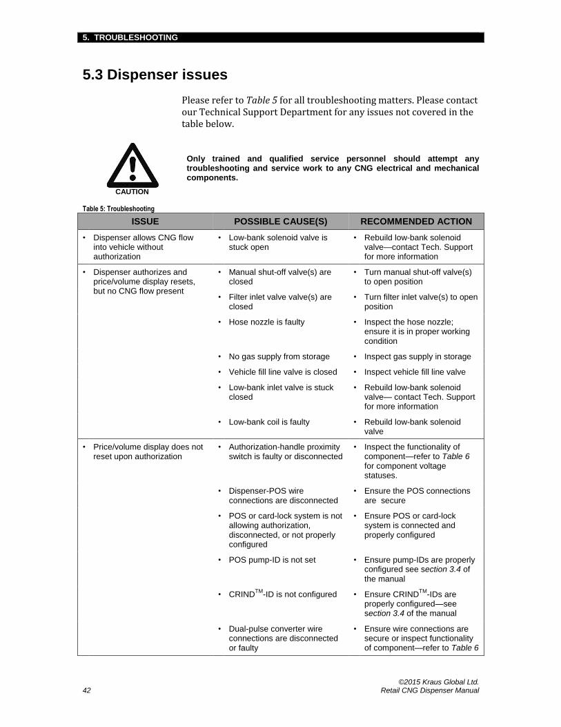
5.3 Dispenser issues
Please refer to Table 5 for all troubleshooting matters. Please contact our Technical Support Department for any issues not covered in the table below.
CAUTION
Only trained and qualified service personnel should attempt any troubleshooting and service work to any CNG electrical and mechanical components.
Table 5: Troubleshooting
ISSUE POSSIBLE CAUSE(S) RECOMMENDED ACTION
• Dispenser allows CNG flow into vehicle without authorization
• Low-bank solenoid valve is stuck open
• Rebuild low-bank solenoid valve—contact Tech. Support for more information
• Dispenser authorizes and price/volume display resets, but no CNG flow present
• Manual shut-off valve(s) are closed
• Turn manual shut-off valve(s) to open position
• Filter inlet valve valve(s) are closed
• Turn filter inlet valve(s) to open position
• Hose nozzle is faulty • Inspect the hose nozzle; ensure it is in proper working condition
• No gas supply from storage • Inspect gas supply in storage
• Vehicle fill line valve is closed • Inspect vehicle fill line valve
• Low-bank inlet valve is stuck closed
• Rebuild low-bank solenoid valve— contact Tech. Support for more information
• Low-bank coil is faulty • Rebuild low-bank solenoid valve
• Price/volume display does not reset upon authorization
• Authorization-handle proximity switch is faulty or disconnected
• Inspect the functionality of component—refer to Table 6 for component voltage statuses.
• Dispenser-POS wire connections are disconnected
• Ensure the POS connections are secure
• POS or card-lock system is not allowing authorization, disconnected, or not properly configured
• Ensure POS or card-lock system is connected and properly configured
• POS pump-ID is not set • Ensure pump-IDs are properly configured see section 3.4 of
the manual
• CRINDTM
-ID is not configured • Ensure CRINDTM
-IDs are properly configured—see section 3.4 of the manual
• Dual-pulse converter wire connections are disconnected or faulty
• Ensure wire connections are secure or inspect functionality of component—refer to Table 6

5. TROUBLESHOOTING
©2015 Kraus Global Ltd. Retail CNG Dispenser Manual 43
Table 5: Troubleshooting (continued)
ISSUE POSSIBLE CAUSE(S) RECOMMENDED ACTION
• Price/volume display resets upon authorization, but does not show any further readings during fuel delivery
• Wires are loose or disconnected at mass flow meter or at explosion-proof junction box
• Ensure all wire connections to the mass flow meter and in the junction box are secure
• Mass flow meter is faulty • Use Micro Motion® Prolink to inspect mass flow meter functionality—contact Tech. Support for more information
• MICONTM
-mainboard is faulty • Replace mainboard—refer to section 4.4 of the manual
• Pump node is faulty • Replace pump node
• Dual-converter board connection is loose or board is faulty
• Ensure wire connections are secure or inspect functionality of component—refer to Table 6
for component voltage statuses
• Display stops reading within 5 – 10 seconds of authorization, but CNG continues to flow
• Low-bank solenoid valve remains open during temperature compensation target-fill calculation
• Rebuild low-bank solenoid valve
• Dispenser overfills vehicles • MICONTM
parameters are not properly configured
• Review MICONTM
configurations. You will require an Info-Pac for this procedure—contact our Technical Support Department for more information
• Temperature probe is not reading correctly
• Compare displayed temperature to actual ambient temperature. If there are discrepancies, contact our Technical Support Department
• Low-bank solenoid valve is stuck open
• Rebuild low-bank solenoid valve
• Pressure transmitter is faulty • Replace pressure transmitter—contact Tech. Support for more information
• Dispenser under-fills vehicles (continues next page)
• MICONTM
parameters are not properly configured
• Review MICONTM
configurations. An Info-Pac is required for this procedure—contact Tech. Support for more information
• Temperature probe is not reading correctly
• Compare displayed temperature to actual ambient temperature. If there are discrepancies, contact Tech. Support for further assistance
This table continues next page

5. TROUBLESHOOTING
©2015 Kraus Global Ltd. 44 Retail CNG Dispenser Manual
Table 5: Troubleshooting (continued)
ISSUE POSSIBLE CAUSE(S) RECOMMENDED ACTION
• Dispenser under-fills vehicles (continued)
• MICONTM
is ending transactions on minimum flow conditions
• Inspect storage supply; there may not be sufficient fuel to continue transactions
• MICONTM
minimum flow set too high
• Reconfigure MICONTM
parameters. An Info-Pac is required for this procedure—contact Tech. Support for more information
• Pressure transmitter is faulty • Replace pressure transmitter—contact Tech. Support for more information
• Pressure gauge does not correspond with vehicle gauge
• Pressure transmitter is faulty • Replace pressure transmitter—contact Tech. Support for more information
• Faulty vehicle gauge • Observe the pressure of the dispenser pressure gauge, vehicle pressure gauge, and dispenser pressure transmitter to see where the discrepancy is
• Info-Pac settings are not properly configured
• Verify settings to ensure they are configured properly. An Info-Pac is required for this procedure—contact Tech. Support for more information
ADVICE
Please contact our Technical Support Department at 1-204-663-3601 for any issues not covered in the table above.
5. TROUBLESHOOTING
©2015 Kraus Global Ltd. Retail CNG Dispenser Manual 45
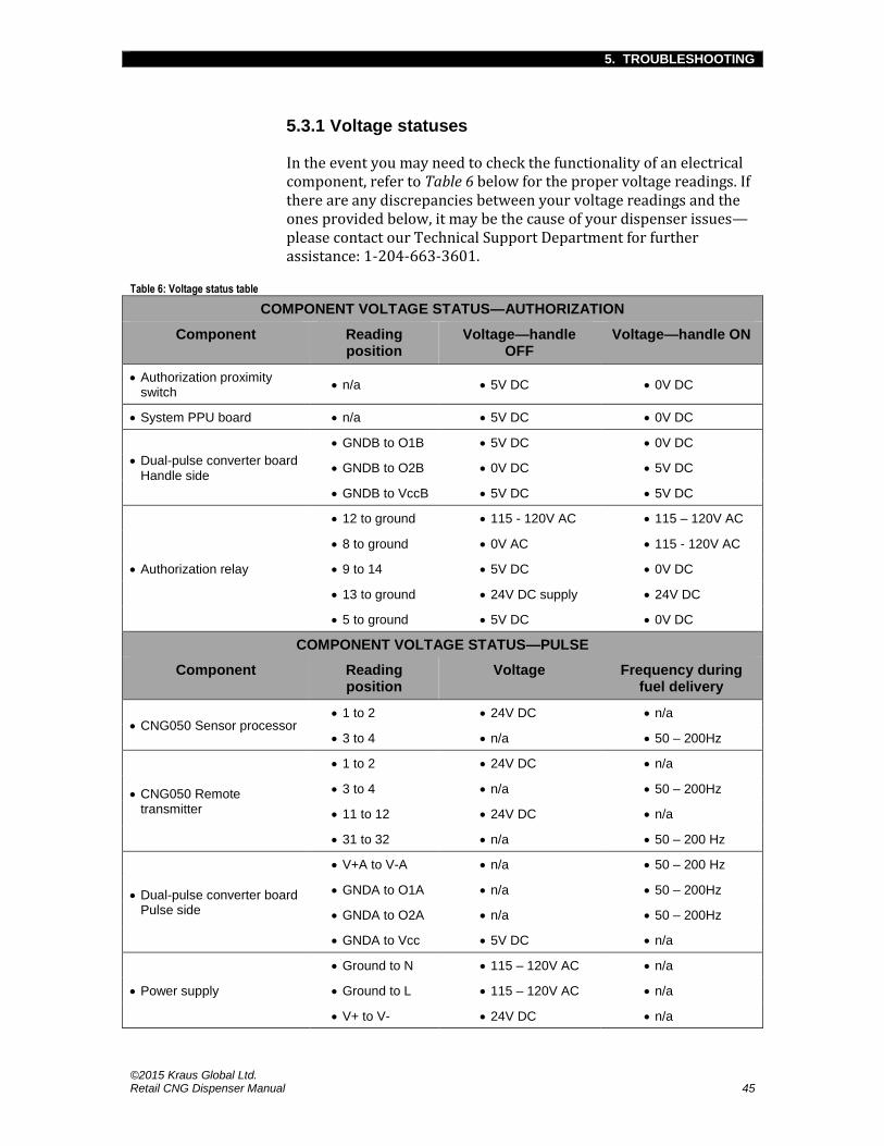
5.3.1 Voltage statuses
In the event you may need to check the functionality of an electrical component, refer to Table 6 below for the proper voltage readings. If there are any discrepancies between your voltage readings and the ones provided below, it may be the cause of your dispenser issues—please contact our Technical Support Department for further assistance: 1-204-663-3601.
Table 6: Voltage status table
COMPONENT VOLTAGE STATUS—AUTHORIZATION
Component Reading position
Voltage—handle OFF
Voltage—handle ON
Authorization proximity switch
n/a 5V DC 0V DC
System PPU board n/a 5V DC 0V DC
Dual-pulse converter board Handle side
GNDB to O1B 5V DC 0V DC
GNDB to O2B 0V DC 5V DC
GNDB to VccB 5V DC 5V DC
Authorization relay
12 to ground 115 - 120V AC 115 – 120V AC
8 to ground 0V AC 115 - 120V AC
9 to 14 5V DC 0V DC
13 to ground 24V DC supply 24V DC
5 to ground 5V DC 0V DC
COMPONENT VOLTAGE STATUS—PULSE
Component Reading position
Voltage Frequency during fuel delivery
CNG050 Sensor processor 1 to 2 24V DC n/a
3 to 4 n/a 50 – 200Hz
CNG050 Remote transmitter
1 to 2 24V DC n/a
3 to 4 n/a 50 – 200Hz
11 to 12 24V DC n/a
31 to 32 n/a 50 – 200 Hz
Dual-pulse converter board Pulse side
V+A to V-A n/a 50 – 200 Hz
GNDA to O1A n/a 50 – 200Hz
GNDA to O2A n/a 50 – 200Hz
GNDA to Vcc 5V DC n/a
Power supply
Ground to N 115 – 120V AC n/a
Ground to L 115 – 120V AC n/a
V+ to V- 24V DC n/a


APPENDIX
©2015 Kraus Global Ltd. Retail CNG Dispenser Manual Appendix-1
APPENDIX
A.1 Component descriptions and specifications
Air purge system components
The air purge system for the Retail unit is composed of several components, including a purge fan, Magnehelic pressure gauge, pressure switch, solid-state timer, and relay.
Purge fan
The purge fan is used to pressurize the upper cabinet of the Retail dispenser. The positive air pressure ensures that no methane can enter the electronics cabinet in case of a gas leak.
Specifications
HP 1 / 10
Volts 115V
HZ 50 / 60
Amps 1.85 / 2.05
RPM 1320 / 1430
CFM 549 @ Free Air 60HZ
Purge fan ducting—installation guidelines
Depending on site and atmospheric conditions, condensation may form in the ducting from the purge fan to the dispenser cabinet, as well as in the cabinet enclosure itself. This is caused by excessive moisture in the purge air supply.
Since conditions vary from site-to-site, it is not possible to address each unique situation; however, the following guidelines may help to mitigate the effects of condensation buildup. Additional measures beyond these guidelines may be required in certain circumstances.
Ideally, purge air delivered to the dispenser should be maintained as close as possible to the ambient outdoor air temperature.
Guidelines continue next page

APPENDIX
©2015 Kraus Global Ltd. Appendix-2 Retail CNG Dispenser Manual
In most cases, when purge air ducting is buried underground, insulation is required to prevent the purge air reaching its dew point within the duct. Site conditions and expected temperature differential between air and ground will dictate the amount of insulation required.
In situations where a moderate difference in outdoor air temperature relative to ground temperature exists, it may be possible to directly bury the purge air ducting without any special preparation.
Duct run length also plays a key role in the formation of condensation. The longer the run, the higher the risk of condensation given the increased time for purge air to cool within the ducting. Both temperature differential and run length should be considered together.
In some cases it may not be possible to eliminate condensation within the purge air ducting due to site conditions and climate. A common solution is to slope the ducting into a sump pit along its run. Accumulated condensate will run into this pit, which can then be automatically drained via a simple fractional horsepower condensate pump or similar float-controlled pump.
o Local code authorities should be consulted to address any regulatory concerns with the use an electric pumping apparatus near a classified location.
ADVICE
For all purge fan installation and maintenance concerns, please contact our Technical Support Department at 204-663-3601.

APPENDIX
©2015 Kraus Global Ltd. Retail CNG Dispenser Manual Appendix-3
Magnehelic pressure gauge
The Dwyer® 2000 Series Pressure Gauge is used to quickly indicate low-air or non-corrosive gas pressures—whether positive, negative or differential—at a high-level of accuracy. The 2000 series is shock, vibration, and overpressure resistant, and operates without manometer fluid, thereby avoiding unnecessary fluid maintenance and any toxicity and leveling problems.
Specifications
Service Air and non-combustible, compatible gases
Housing Die cast aluminum case and bezel, with acrylic cover. Exterior finish coated gray to withstand 168 hour salt spray corrosion test
Accuracy ±2% of full scale throughout range at 70°F (21.1°C)
Pressure limits -20” Hg to 15 psig† ; MP: 35 psig; HP: 80 psig
Overpressure Relief plug opens at approx. 25 psig (1.72bar). Refer to manufacturer for overpressure protection note.
Temperature limits 20 to 140°F ; -6.67 to 60°C
Size 4” (101.6mm) diameter dial face
Weight (approx.) 3.25 lb (1.5 kg)
Approvals CE, UL, CSA, FM
Pressure switch
The Dwyer® 1950 Series Pressure Switch operates as the trigger that initiates power to all dispenser-electronics. The pressure switch is located in the lower cabinet and is programmed to detect a specific level of air pressure, which upon detection, delivers a signal to initiate and maintain power to all dispenser-electronics.
Should the air pressure fall below the threshold, the signal is broken and power to all dispenser-electronics is terminated.
Specifications
Service Air and non-combustible, compatible gases
Temperature limits -40 to 140°F (-40 to 60°C)
Enclosure rating NEMA 3 (IP54), NEMA 7 & 9
Switch type Single-pole double-throw (SPDT)
Electrical rating 15 A@, 125, 250, 480 VAC, 60 Hz. Resistive 1/8 HP @ 125 VAC, 1/4 HP @ 250 VAC, 60 Hz.
Electrical connections 3 screw type, common, normally open and normally closed
Process connections 1/8” female NPT
Weight (approx.) 3.25 lb (1.5 kg)
Approvals CE, UL, CSA, FM

APPENDIX
©2015 Kraus Global Ltd. Appendix-4 Retail CNG Dispenser Manual
Pressure timer
The Omron® H3YN Solid-state Timer operates as a precautionary device that ensures sufficient time is allowed for the upper cabinet to become fully pressurized. The timer is located in the explosion-proof junction box in the lower cabinet and receives signals from the pressure switch. After receiving the signal, the timer initiates a minute-and-a-half buffer to allow the upper cabinet to become fully pressurized. Once the buffer time has elapsed, the timer transmits its own signal to a 110/120V AC relay, which sends the signal to the terminal hub in the upper cabinet.
Specifications
H3YN-2/-4/-4-Z H3YN-21/-41/-41-Z
Time ranges 0.1s to 10 min (1s; 10s; 1 min; 10 min max)
0.1 min to 10 h (1 min; 10 min; 1h; 10h max)
Operating mode ON-delay; interval; flicker OFF start; flicker ON start (selectable with DIP switch)
Accuracy of operating time
±1% FS max. (1 s range: ±1%±10 ms max.)
Setting error ±10%±50% ms FS max.
Reset time Min. power-opening time: 0.1s max. (includes halfway reset)
Life expectancy Mechanical: 10,000,000 operation mins. (under no load at 1,800 operations/h)
Electrical: DPDT – 500,000 operation mins. (5 A at 250
VAC, resistive load at 1,800 operations/h)
4PDT – 200,000 operation mins. (H3YN-4-Z/-41-Z: 100,000 operation mins.)
Weight (approx.) 50 g
Air purge system relay
See Air purge system/authorization relay.

APPENDIX
©2015 Kraus Global Ltd. Retail CNG Dispenser Manual Appendix-5
Power supply
IDEC’s PS5R Slim Line Series Power Supply provides 24V DC power to the remote transmitter(s), authorization relay(s), and authorization timer(s). One power supply is required for each hose.
Specifications
Output capacity 30W
Input voltage (single-phase, 2-wire)
85 to 264V AC
100 to 370V DC
Input current (max.) 100 VAC – 0.9A 200 VAC – 0.6A
Internal fuse rating 3.15A
Typical efficiency 12V DC—78%; 24V DC—80%
Output current ratings 12V DC—2.5A; 24V DC—1.3A
Voltage adjustment ±10% (V. Adjustment control on front)
Approvals EMC:E61204-3 (EMI: Class B, EMS: Industrial); c-UL (CSA 22.2 No. 14); UL1604; UL508; LVD: EN60950; EN50178; UL1310 Class 2; c-UL (CSA 22.2 No. 213 and 223)
Weight (approx.) 250 g
Air purge system/authorization relay
The Omron® MY-model General-purpose Relay is used for various dispenser applications.
A 110/120V AC relay is used to receive signals from the pressure timer and transmit signals to the terminal hub, where electrical power is distributed to all dispenser-electronics. This relay is located beside the pressure timer in the lower cabinet.
A 24V DC relay is used to receive signals from the authorization handle and transmit them to the MICONTM, commencing and terminating refueling transactions. This relay is located in the upper cabinet.
Specifications
110/120V AC 24V DC
Rated current 9.9/10.8mA @ 50Hz; 8.4/9.2 mA @ 60Hz 37.7 mA
Coil resistance 4,430 Ω 636 Ω
Power consumption 0.9 to 1.1 VA (60Hz) 0.9 W
Max. operating freq. Mechanical: 18,000 operations/hr; Electrical: 1,800 operations/hr (under rated load)
Approvals VDE (112467UG, IEC 255, VDE 0435); UL508 (41515); CSA C22.2 (LR31928); IMQ (EN013 to 016); LR (98/10014); SEV (99.5 50902.01)
Weight (approx.) 35 g

APPENDIX
©2015 Kraus Global Ltd. Appendix-6 Retail CNG Dispenser Manual
Authorization timer
The Omron® H3DS-ML Solid-state Timer is used to ensure the dispenser accurately records the amount of fuel dispensed at the end of a refueling transaction.
Dispenser-electronics terminate a refueling transaction quicker than the MICONTM can terminate fuel delivery. The authorization timer is used to delay the dispenser-electronics, allowing the MICONTM to end fuel delivery at the same time.
Specifications
Rated supply voltage 24 to 230V AC (50/60Hz)/24 to 48V DC
Operating voltage range 85% to 110% of rated supply voltage
Life expectancy Mechanical: 10 million operations/min. (under no load at 1,800 operations/h)
Electrical: 100,000 operations/min. (5 A at 250V AC, resistive load at 360 operations/h)
Approvals UL508; CSA C22.2 (14); EN61812-1; IEC60664-1 4 kV/2; VDE0106/P100; IEC60947-5-1
Weight (approx.) 70 g
Dual pulse converter board
Kraus’ Dual-Pulse Converter Board operates as the main interface between the MICONTM and dispenser-electronics. The converter board translates signals from the authorization handle to the MICONTM, and from the MICONTM to the dispenser-displays. One converter board is required for each hose and is located in the upper cabinet.

APPENDIX
©2015 Kraus Global Ltd. Retail CNG Dispenser Manual Appendix-7
ADVICE
For further details on dispenser components, please refer to the part manufacturer or contact our Engineering or Technical Support departments.
Micro Motion® CNG050 flow meter
The Micro Motion® CNG050 is a Coriolis mass flow meter designed specifically for measuring CNG. The meter’s refined accuracy and sensitivity allow users the flexibility of using the sensor for standard automobile dispenser configurations or high-flow dispensers for heavy duty fleets.
Flow specifications
Mass Standard volume(1)
lb/min kg/min SCFM Nm3/hr
Flow range 2 to 220 1 to 100 40 to 4444 68 to 7550
Zero stability 0.02 0.009
Batch accuracy(2)(3)
±0.50% of batch
Repeatability(2)
±0.30% of rate
(1) CNG with SG = 0.66 at 60°F (15.5°C) and 14.73 psia (1 bar-a).
(2) In terms of percent of total batch delivered on CNG.
(3) Accuracy is under typical CNG batch/dispensing conditions. Typical batch/dispensing conditions are defined as those where the flow rate is greater than 4lbs/min or 109kg/hr.
Pressure ratings
psi bar
Flow tube rating 5,000 345
Pressure limits(1)
5,000 345
Union to NPT adapter piece rating (2)
4,600 317
House rating Housing is not rated for pressure containment.
PED compliance Sensor complies with council directive 97/23/EC of 29-May-1997 on Pressure equipment
(1) All fittings are rated to 5,000 psi (345 bar) – the Union SWG type fitting according to ASME B31.3, and the SAE fitting according to SAE J1453.
(2) Pressure rating of the additional adapter piece (#12 O-ring face seal to female NPT) that is provided with process connection option 239.

APPENDIX
©2015 Kraus Global Ltd. Appendix-8 Retail CNG Dispenser Manual
Micro Motion® CNG050 flow meter (continued)
Environmental limits
°F °C
Process fluid temp. limits
-40 to +257 -40 to +125
Ambient temp. limits
CSA and MMI standard (no approval)
-40 to +140 -40 to +60
ATEX
Humidity limits 5 to 95% relative humidity, non-condensing at 140°F / 60°C
Vibration limits Meets IEC 68.2.6, endurance sweep, 5 to 2,000 Hz, 50 sweep cycles at 1.0 g
Weight
Sensor with core processor 16 lbs / 7 kg
Sensor with integrally mounted transmitter
18 lbs / 8 kg
Materials
Wetted parts (1)
316L stainless steel
Sensor housing 304L stainless steel
Core processor housing
CF-3M stainless steel or polyurethane-painted aluminum; NEMA 4X (IP65)
(1) General corrosion guidelines do not account for cyclical stress and therefore should not be relied upon when choosing a wetted material for your Micro Motion® flow meter. Please refer to Micro Motion’s corrosion guide for material compatibility information.

APPENDIX
©2015 Kraus Global Ltd. Retail CNG Dispenser Manual Appendix-9
KAF 402™ solenoid inlet valve
The Kraus model KAF 402™ solenoid valve has been specifically engineered for high-pressure CNG service. It is a unique valve that features a high flow rate; a high-pressure rating; a compact design; and low power requirements, meaning that it does not require the assistance of a lifting coil and relay. These features make this panel mount control valve an excellent choice for sequencing or ESD applications in natural gas dispensing systems.
The KAF 402™ series is available in North American (N) and European (E) models. The KAF 402™-N is approved by the CSA, designed to the ASME code, and complies with NFPA 52 and CGA B108 standards. The KAF 402™-E is TÜV and ATEX approved, and complies with European PED standards.
Technical data (N) (E)
Operation 2-way solenoid valve, normally closed
Design pressure 5,000 psi 345 bar
Operating pressure range—TÜV approved values
73 to 5,000 psi 5 to 345 bar
Test pressure 6,000 psi 414 bar
Burst pressure 25,000 psi 1,700 bar
Operating temperature—CSA approved values
-40°F to +150°F -40°C to +66°C
Operating temperature—TÜV approved values
-40°F to +122°F -40°C to +50°C
Flow coefficient (Cv) 3.3
Inlet and outlet ports SAE-8 (3/4 – 16) G1/2” ISO228/1
Electrical specifications (N) (E)
Connection ½” NPT
(North American) DIN Cable (European)
Power consumption 10 Watts (average)
Materials
Body 7075 Aluminum, Anodized Seat 304 Stainless Steel
Piston PEEK Seals Nitrile

APPENDIX
©2015 Kraus Global Ltd. Appendix-10 Retail CNG Dispenser Manual
Fueling nozzles
Kraus CNG dispensers are compatible with Type 1 and Type 2 nozzles for use in either NGV1 (passenger vehicles) or NGV2 (large fleet vehicles) refueling applications. The following are some examples of commonly used nozzles; please contact your salesperson or our Technical Support Department for ordering information and other details.
Type 1 nozzle
The Type 1 nozzle incorporates an integrated vent valve that allows for safe venting and detaching in a single motion.
WEH-TK16 Type 1 nozzle for NGV1 applications
OPW CT1000S Type 1 nozzle for NGV1 applications
WEH-TK17 Type 1 nozzle for NGV1 applications
OPW CT5000S Type 1 nozzle for NGV2 applications
Type 2 nozzle
The Type 2 nozzle must be coupled with an external vent valve that requires yout to vent the gas before choosing to disconnect the nozzle from the vehicle’s receptacle.
Staubli-CMV 08 Type 2 nozzle for NGV1 applications

APPENDIX
©2015 Kraus Global Ltd. Retail CNG Dispenser Manual Appendix-11
A.2 Maintenance task list
SCHEDULE MAINTENANCE TASK
AT STARTUP
Inspect fill hoses and breakaway components
Tighten all electrical terminal connections and check all harness connections
Dispenser leak test
DAILY
Inspect the dispenser and all of its components. If any damages are found, vent, disconnect AC power, and disallow further use until maintenance authority can repair the damages.
Drain dispenser filters
2 WEEKS AFTER STARTUP
Change filter elements—it is common that above normal amounts of debris or liquids from newly installed pressure lines may be present
EVERY 2 WEEKS
Inspect fill nozzle seals for leaks and wear
Inspect flow control or sequencing valves during filling operation
Inspect the sequencing valves for leaks
Inspect fill hoses and hose breakaway components
EVERY 6 MONTHS
Change dispenser filters
Dispenser leak test
Visual leak inspection of pressure relief device—if internal leakage has occurred there will be visible frosting on the outlet tubing
EVERY YEAR
Tighten all electrical terminal connections and check all harness connections
Rebuild sequencing valve
Inspect fill nozzle valve, rebuild if necessary
Inspect pressure regulator, rebuild if necessary
EVERY 2 YEARS Replace fill hose
EVERY 5 YEARS Recertify pressure relief device


GLOSSARY
©2015 Kraus Global Ltd. Retail CNG Dispenser Manual Glossary-1
GLOSSARY
B
Bar. A metric unit of pressure; 1 bar = 14.5038 psi
Breakaway. A fuel dispenser-hose feature that allows the hose to break apart and cease gas flow in the event that a vehicle drives away while the nozzle is still connected to the vehicle’s receptacle.
Buffer storage system. A fuel storage system consisting of a single large storage bank, generally used, but not limited to, large vehicles, such as buses and trucks.
C
Card-lock system. A security system incorporated into a dispenser to prevent unauthorized used. Fleet/fuel cards are required to authorize a refueling transaction.
Cascade storage system. A fuel storage system consisting of two or three storage banks pressurized at different levels. The storage banks are used sequentially in a pre-determined sequence.
CNG. Compressed Natural Gas; an environmentally friendly fuel alternative to petrol (gasoline), diesel, and propane
CNG050. A mass-flow meter consisting of transmitters and sensors designed to measure CNG flow, manufactured by Micro Motion®.
Coalescing filtration. A filtration method that separates water aerosols and droplets, as well as solid particles, from gases; the standard and recommended method of filtration for all Kraus CNG dispensers
Communicator. A standard MICONTM remote used to set dispenser prices and check totalizer readings (may not be apply to Retail dispensers).
CRINDTM. Card-Reader-In-Dispenser; a user interface that incorporates a card reader, keypad, and screen display that allows customers to make retail transactions at the dispenser
E
ESD. Emergency Shut-Down; a safety feature that allows users to terminate all power and gas flow to immediate fuel dispensers—ESD buttons are not standard features, but Kraus CNG dispensers are equipped with ESD terminals that can enable this function.
H
GLOSSARY
©2015 Kraus Global Ltd. Glossary-2 Retail CNG Dispenser Manual
High-flow dispenser. A CNG filling system designed to quickly refuel vehicles
I
Info-Pac. A MICONTM 500C remote-control programmer
K
KAF 402™. A Kraus-original solenoid valve, engineered specifically for high-pressure CNG applications; see also Solenoid valve.
M
Mainboard. A circuit-board housing vital electrical components, such as the CPU
MICONTM 500C. A Kraus-manufactured pump-controller
O
O-ring. A small, circular elastic joint used to seal or fill space between mating components.
P
Particulate filtration. A filtration method designed to remove solid particles from gases.
PLC. Programmable Logic Controller; a computer used to automate electromechanical processes, such as dispensers and assembly lines.
POS system. Point-Of-Sale system; a retail system that allows fuel station attendants to control and authorize fuel dispensers from their terminal
Positive pressure. An air pressure greater than that of its surrounding environment; used as an engineering technique to isolate an area from outside contaminants
Pressure vessel. A sealed container designed to hold gases or liquids at a considerably higher pressure than that of the ambient atmosphere.
PSI. Pound-force per Square Inch; a unit of pressure
Pump-controller. An electronic device used to control the voltage supplied to the fuel-pump and other signals used within the fuel-pump.
Pump door node. A circuit-board located on the reverse side of the upper cabinet door of the Retail dispenser, consisting of components affecting the dispenser display electronics.

GLOSSARY
©2015 Kraus Global Ltd. Retail CNG Dispenser Manual Glossary-3

GLOSSARY
©2015 Kraus Global Ltd. Glossary-4 Retail CNG Dispenser Manual
R
Rebuild kit. A Krause package including parts and instructions necessary to rebuild a dispenser component, such as a solenoid valve; sold separately from dispenser packages
S
SAE J1616. A standard developed by SAE International that describes recommended practices for using compressed natural gas as fuel for vehicles.
Solenoid valve. An electromechanically controlled valve; for CNG dispensers, it is used to control gas flow from the storage banks to a vehicle receptacle.
Split-flow. A single fuel dispenser with one hose designed for a standard-flow filling system and another designed for a high-flow filling system.
Split-pressure. A single fuel dispenser designed to dispense fuel at two different pressure options.
Standard-flow dispenser. A CNG filling system designed to refuel passenger vehicles.
T
Totalizer. A function within the MICONTM 500C that sums up the total dollar and volume sales.

INDEX
©2015 Kraus Global Ltd. Retail CNG Dispenser Manual Index-1
INDEX
#
2-wire, 24
A
anchor, 16
B
breakaway, 14, 21
C
connection
communication, 17 electrical, 8, 17, Appendix-2 pressure line, 17
convey, 10
D
diagnostic card, 27
F
filters
Coalescing, 18 installation, 19 KAF 402™ solenoid valve, 36 maintenance, 32 Particulate, 18 placement, 18 purge fan, 37 size, 18
G
gauge
Magenhelic, 22, 37, Appendix-1 pressure, 22, 23, 33
grounded, 10
I
Intended users, see users
K
keys, 15, 24, 35
L
lockout, 24
M
menu
CRINDTM Main Menu, 27 Diagnostic Startup Menu, 27
MICONTM 500C, 4, see MICONTM
MICONTM, 35; 38
N
notifications, 3
P
pit frame, 14, 16
pump door node, 24, 26
purge fan, 22, 37, Appendix-1
Purpose, 1
S
SAE J1616, 13
screw thread, 16
storage system(s)
buffer, 5 cascade, 5, 23
U
users, 1; Appendix-5
V
voltage, 40, 41, 43
W
warnings, 3
warranty, 3, 28

©2015 Kraus Global Ltd. All Rights Reserved
Printed in Canada