(pdf) , 88 pages
TRANSCRIPT
-. ~~GIBB
JORF LASFAR POWER PLANT
ASH DISPOSAL SITE DEVELOPMENT
F~-~~~~~~~ ~~~~~~;~~-
:, ~~~~t
i- T 4
PHASE 2B - DESIGN OF LONG TERM SITE
INTERIM REPORT
NOVEMBER 1996
J96291 B
Pub
lic D
iscl
osur
e A
utho
rized
Pub
lic D
iscl
osur
e A
utho
rized
Pub
lic D
iscl
osur
e A
utho
rized
Pub
lic D
iscl
osur
e A
utho
rized
Pub
lic D
iscl
osur
e A
utho
rized
Pub
lic D
iscl
osur
e A
utho
rized
Pub
lic D
iscl
osur
e A
utho
rized
Pub
lic D
iscl
osur
e A
utho
rized

I
DOCUMENT CONTROL SHEET
PROJECT: Jorf Lasfar Power Plant JOB NO: J96291BAsh Disposal Site Development
TITLE: Phase 2B, Design of Long Term Slte, Interim Report
Prepared by Reviewed by Approved by
ORIGINAL " E
S.D. Clamp R.M. Wingfield J E. Crosfield
1996__ _ _ _ _OATS TUSIAIE innO,E AIJAUE
I_ _
REVISION ISUIWtE SIGOWTIE _lOATME
REVISION i . _ .. IDATE 51MURE STURE SKN^TURE
|REVISION DIA EO
DATE NTURE MOTUnIE U E
This." ror,andinmaion orsiewich it-r s i,sprovided byGISslelyfor iymauseadreince byits Cletinpeu Gmmance f ,lB sdead ahbes
under is contract with tie Client. Any adice, opins, or oonrnerndaom nwithntis report shotld be rad and eied upn ony In the contedof ch repot as a whoee.The adviceand opinions m thisn rport ar' _ P on the medonnab0n made Owv111bl to GI8 at ie date of this eport and on Cuent UK sndards, s, technooyand Omsu eon praces as at d date ofr iis fepot Foowing fina deknery of dis rpor to Si Clent, GIBB will hae no urther obhkgatirs or duty to advise tOe Chaton any nmaSem, inluding devekopment a*fean the infonnation or made. proided in t s rpot This rt has been prepared by GIB in Sir profesional capacity asConsultirg Engineers The con of tr repor do not m any w_y, pqupor tf include n maeo lega advice or opinon. Thts eport is prepared in accordance wihtie tems and eondbons of GIBBs onbact with the Client Regard should be had to Sin m. wt a ondrbons when consideing anor placing ny riance on ihsrpr Shod the Cient wh to ae i ot o a Third Payor thparts ,G myat fs dicrebon, agee toshreles proved tat
(a) GIBBEs wnr agrenent is otined prior to sucha , and(b) By releaae of te report to te Third Party. tSat Third Party does not acquire any rigt. conbas, or edwerwse. whatsoer aainst GSB and
GIS. acordingly, assume no dutibes, iabit or oblgatons to brat Third Party, and(c) GBB accepts no respotsibility for any lss or damge d by mi. Cint or for any cordlit of GIBBs irsad na out of Si Cierts
releeof thispor totheThird Party.

a
I
I
CMS GENERATION CO. &ABB ENERGY VENTURES INC.
JORF LASFAR POWER PLANT
ASH DISPOSAL SITE DEVELOPMENT
PHASE 2BDESIGN OF LONG TERM SITE
INTERIM REPORT
November 1996
J96291B
Revision 0

I
I
JORF LASFAR POWER PLANTASH DISPOSAL SITE DEVELOPMENT
PHASE 2BDESIGN OF LONG TERM SITE
INTERIM REPORT
CONTENTS
Section Description Page
EXECUTIVE SUMMARY
1 INTRODUCTION 1-1
2 REGIONAL AND SITE CHARACTERISTICS 2-1
2.1 Regional Physiography and Geology 2-12.2 Historical Summary of Port Quarry 2-22.3 Topography of Port Quarry 2-32.4 Geological and Hydrogeological Conditions at the Site 2-42.5 Groundwater and Site Sensitivity 2-9
3 METEOROLOGICAL DATA 3-1
3.1 General 3-13.2 Rainfall 3-13.3 Temperature 3-13.4 Wind 3-2
4 WASTE STREAM 4-1
4.1 Waste Stream 4-1
5 SITE END USE 5-1
5.1 Site End Use 5-1
6 CONCEPTUAL DESIGN 6-1
6.1 General 6-16.2 Voidspace and Landform 6-16.3 Settlement and Compaction Requirements 6-26.4 Operational Ufetime 6-36.5 Site Preparation and Design 6-36.6 Site Access and Facilities 6-56.7 Site Restoration 6-6
7 OPERATIONAL PROCEDURE 7-1
7.1 General 7-17.2 Bund and Lagoon Construction 7-17.3 Ash Conditioning 7-17.4 Placement Method 7-27.5 Dust Control 7-47.6 Monitoring 7-4
J96291B November1996jorf4as2binjO.doc Revision 0
8 PREUMINARY COST ESTIMATE 8-1
8.1 General 8-1
9 IMPLEMENTATION SCHEDULE 9-1
9.1 General 9-1
10 RECOMMENDED FURTHER INVESTIGATIONS 10-1
10.1 General 10-110.2 Boreholes and Piezometers 10-1
11 DISCUSSION, CONCLUSIONS AND RECOMMENDATIONS 11-1
12 REFERENCES 12-1
Figures
1.1 Jorf Lasfar Location Map
1.2 Long Term Site Location Map
2.1 Geological and Hydrological Features
2.2 In-fill Material
2.3 Predicted Flood Levels
2.4 Groundwater and Electrical Conductivity Levels
4.1 Ash Stream for Long Term Site
6.1 Restoration Surface
6.2 Operational Phases
6.3 Operational Phase 1 (Showing First Three Cells)
6.4 Section A-A' Through Long Term Site
6.5 Lagoon Conceptual Design
6.6 Perspective Views of the Long Tern Site Before and After Disposal
9.1 Preparation Contract Schedule
9.2 Operational Schedule
Tables
2.1 Composite Lithological Log of Port Quarry
2.2 Geochemical Summary
3.1 Monthly Total Rainfall For Safi
J9611 B Novenber 1996jorft-ls_2WLrO.doc Revision 0
3.3 Mean and Maximum Temperatures For Safi
8.1 Cost Estimate
Plates
2.1 Port Quarry Entrance and Stockpiled Soil Overburden and Madl Waste2.2 Port Quarry Panorama Viewed Northwards
2.3 Backfilled Soil Overburden on Westem Side of Quarry
2.4 Logged Section of the Lower and Upper Quarry Faces
2.5 Oil Contamination on Northem Side of Quarry
2.6 Oil Residue Deposited Following Recession of Surface Water
J96291B RenNove 1996rfas\2bhrO.doc Rev,o 0

I
EXECUTIVE SUMMARY
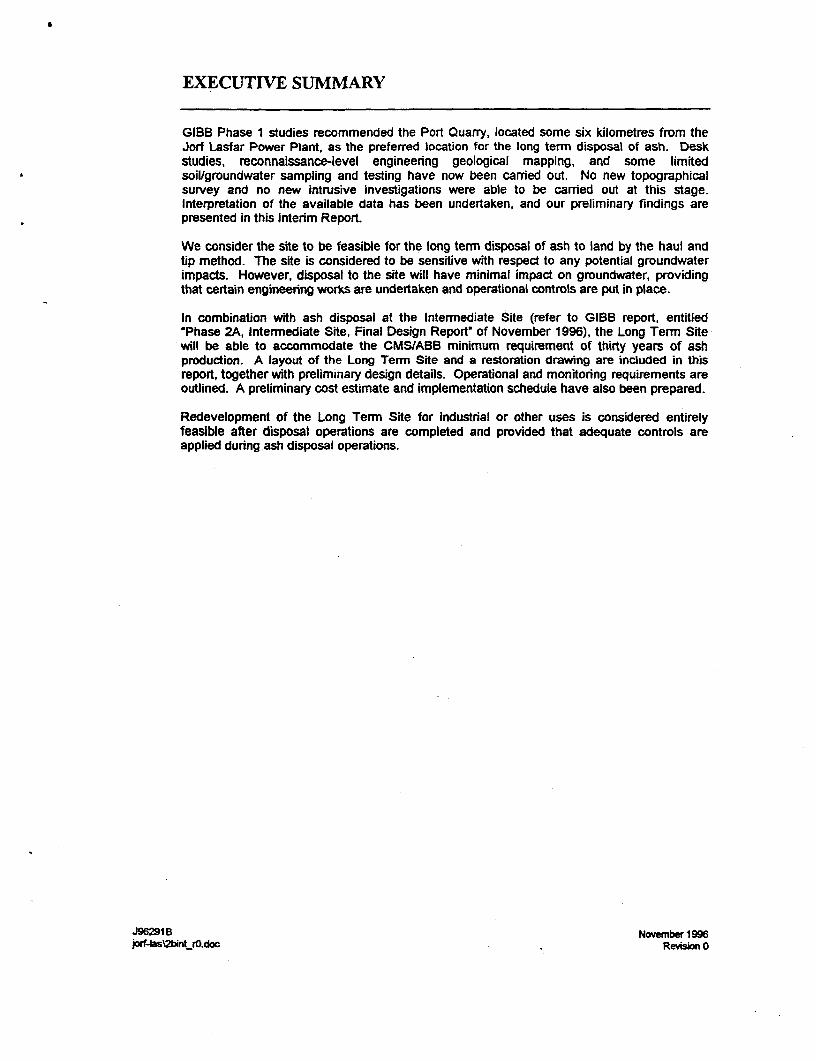
GIBB Phase 1 studies recommended the Port Quarry, located some six kilometres from theJorf Lasfar Power Plant, as the preferred location for the long termn disposal of ash. Deskstudies, reconnaissance-level engineering geological mapping, and some limitedsoilgroundwater sampling and testing have now been carried out. No new topographicalsurvey and no new intrusive investigations were able to be carried out at this stage.Interpretation of the available data has been undertaken, and our preliminary findings arepresented in this Interim Report.
We consider the site to be feasible for the long term disposal of ash to land by the haul andtip method. The site is considered to be sensitive with respect to any potential groundwaterimpacts. However, disposal to the site will have minimal impact on groundwater, providingthat certain engineering works are undertaken and operational controls are put in place.
In combination with ash disposal at the Intermediate Site (refer to GIBB report, entitled"Phase 2A, Intermediate Site, Final Design Report" of November 1996), the Long Term Sitewill be able to accommodate the CMSIABB minimum requirement of thirty years of ashproduction. A layout of the Long Term Site and a restoration drawing are included in thisreport, together with preliminary design details. Operational and monitoring requirements areoutlined. A preliminary cost estimate and implementation schedule have also been prepared.
Redevelopment of the Long Term Site for industrial or other uses is considered entirelyfeasible after disposal operations are completed and provided that adequate controls areapplied during ash disposal operations.
J96291 B Novemnber 1996jorf-lasognkjo.doc Revision 0

I
I INTRODUCTION
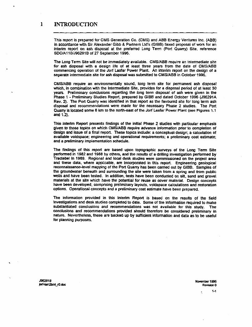
This report is prepared for CMS Generation Co. (CMS) and ABB Energy Ventures Inc. (ABB)in accordance with Sir Alexander Gibb & Partners Ltd's (GIBB) faxed proposal of work for aninterim report on ash disposal at the preferred Long Term (Port Quarry) Site, referenceSDC/AI 10/J96291 B of 27 September 1996.
The Long Term Site will not be immediately available. CMS/ABB require an intefmediate sitefor ash disposal with a design life of at least three years from the date of CMS/ABBcommencing operation of the Jorf Lasfar Power Plant. An interim report on the design of aseparate intermediate site for ash disposal was submitted to CMS/ABB in October 1996.
CMS/ABB require an environmentally sound, long term site for permanent ash disposalwhich, in combination with the Intefmediate Site, provides for a disposal period of at least 30years. Preliminary conclusions regarding the long temn disposal of ash were given in thePhase I - Preliminary Studies Report, prepared by GIBB and dated October 1996 (J96291ARev. 2). The Port Quarry was identified in that report as the favoured site for long term ashdisposal and recommendations were made for the necessary Phase 2 studies. The PortQuarry is located some 6 km to the north-east of the Jorf Lasfar Power Plant (see Figures 1.1and 1.2).
This Interim Report presents findings of the initial Phase 2 studies with particular emphasisgiven to those topics on which CMS/ABB require advance information prior to completion ofdesign and issue of a final report. These topics include: a conceptual design; a calculation ofavailable voidspace; engineering and operational requirements; a preliminary cost estimate;and a preliminary implementation schedule.
The findings of this report are based upon topographic surveys of the Long Tern Siteperformed in 1982 and 1988 by others, and the results of a drilling investigation performed byTractebel in 1989. Regional and local desk studies were commissioned on the project areaand these data, where applicable, are incorporated in this report. Engineering geologicalreconnaissance-level mapping of the Port Quarry has been carried out by GIBB. Samples ofthe groundwater beneath and surrounding the site were taken from a spring and from publicwells and have been tested. In addition, tests have been conducted on silt, sand and gravelmaterials at the site which have the potential for reuse as cover material. Design conceptshave been developed, comprising preliminary layouts, voidspace calculations and restorationoptions. Operational concepts and a preliminary cost estimate have been prepared.
The information provided in this Interim Report is based on the results of the fieldinvestigations and desk studies completed to date. Some of the information required to makesubstantiated conclusions and recommendations was not available for this study. Theconclusions and recommendations provided should therefore be considered preliminary innature. Nevertheless, these are backed up by sufficient information and data as to be usefulfor planning purposes.
J96291B November 1996j0rf4asi2bhr0.doc Reviion 0
1-1

I
2 REGIONAL AND SITE CHARACTERISTICS
2.1 Regional Physiography and Geology
The Jorf Lasfar Power Station and Port is situated within the El Jadida Province, whichextends inland from Azemmour in the north-east to Safi 110 km to the south-west.
The northem boundary coincides with the River Oum Rbia, which rises in the Middle AtlasMountains, and is tidal near Azemmour (Figure 1.1). The Province is characterised generallyby a series of broad plateaux varying in elevation from 125 m to 200 m above mean sea level(AMSL). Jorf Lasfar is located along the westem coastal margin of the El Jadida Plateau tothe south-west of Mazagan. The westem edge of the plateau exhibits a typical karstic terrainat an elevation of 50 to 60 m AMSL some 2 to 5 krim inland. This terrain comprises mainlybedded limestones with only a thin soil cover, due to extensive wind erosion.
To the north-west, the ground level falls gradually towards the Atlantic Ocean. A relativelysteep slope is developed about 0.5 km from the shoreline and represents a former cliff line ofPlio-Quatemary age.
The regional geology of the El Jadida Province comprises a folded Pre Cambrian/LowerPalaeozoic basement overlain successively by Mesozoic, Tertiary and Quatemary strata.The basement, which outcrops in the south of the Province, includes schists, dolomites,siltstones, granites and rhyolitic lavas. The succeeding Triassic basalt lavas and Jurassicsandstones outcrop mainly along the banks of the River Oum Rbia.
The Cretaceous strata are subdivided into a lower division of Neocomian age and an upperdivision of Cenomanian age. The Neocomian is represented by red calcareous clays whichoccur north east of Safi and west of Mechra-Benabbou. The Cenomanian (UpperCretaceous) strata are confined mainly to the El Jadida Plateau. The strata comprise a localbasal conglomerate and an overlying sequence represented by calcarenites, martylimestones, marts and quartz sandstones.
The Tertiary strata occur as a broad north-east to south-west trending strip up to 20 km widewhich broadens in the vidnity of Safi and comprises mainly sandy marts and red clays. Thesucceeding Quatemary deposits predominate to the east of the Tertiary outcrop and alsooccur as a thin strip along the coast. The deposits indude uncemented and cementedcalcareous dune sands and calcretes, together with alluvial muds along the permanent rivercourses. The karstic terrain is also characterised by a thin surficial layer of tufa which hasbeen precipitated on much of the limestone outcrop.
J96291B November 1996jo4f-4as12bmt_0.doc Revision 0
2-1
2.2 Historical Summary of Port Quarry
The history of limestone extraction at Port Quany, officially called Jorf Lasfar Quarry, hasbeen determnined from the following data sources:
* detailed site reconnaissance undertaken by GIBB in October 1996
* plans of the proposed extraction and operating quarry submitted to theMoroccan Ministry of Public Works and Communications in 1978 and 1982,respectively
* report prepared by Tractebel (1989), which included a then recent plan of thequarry and the results of ground investigations conducted by LPEE in 1975for the Secondary Ports Authority
Umestone extraction commenced in 1977 at Port Quarry to provide armour stone for theconstruction of the breakwater at Port Jorf Lasfar. According to plans submitted to theMinistry of Public Works in 1978, the proposed boundaries of the quarry comprised an area of750 m x 750 m, with the processing plant and site offices being located to the west.Excavation commenced with the removal and stockpiling of soil overburden along the north-south tract to the west of the quarry. A bench was then developed at about 9 m below groundlevel, remnants of which are still evident in the north-east and north-west comers of thequarry (Figure 2.1). The marly limestones near the top of the upper face, being relativelyweak and closely bedded, were unsuitable for their intended usage at Port Jorf Lasfar andwere stockpiled to the north-west of the quarry.
The underlying massive mardy limestones, however, are strong with widely spaced verticaljoints and occur as large equidimensional blocks which were suitable for use as armour stone.Subsequently, a lower face was developed in the crystalline shelly dolomitic limestones whichare mainly massive and strong to very strong and hence suitable for the Port constructionworks. These faces were progressively worked eastwards with the subhorizontal quarry floorat 36 to 40 mAMSL. The summary borehole logs suggest that the interface between theshelly limestones and an underlying marly limestone corresponds to the level of the quarryfloor. Exploitation of stronger limestones at greater depths would have necessitated theremoval and stockpiling of these marly limestones and groundwater lowering to maintain dryconditions during quarry operations.
A comparison of the quarry plans prepared in 1982 and 1989 indicates that some limitedbackfilling of the quarry along the south-westem and southem faces took place after 1982(Figure 2.2). This backfill comprises soil overburden and mart waste which was previouslystripped from above the usable rock. A comparison of these plans also indicates thatlimestone extraction between 1982 and 1989 was limited to a 40 m advance of the lower facein the north-east comer of the quarry and hence, active rock quarrying probably ceased soonafter 1982.
Since 1989, some reworking and extraction of marl waste has been carried out on a limitedscale adjacent -o the quarry entrance (Plate 2.1). In addition, localised tipping or dumping ofmixed quarry waste, reinforced concrete and limestone boulders has taken place along thewestem and southem margins of the quarry. A large fenced compound on the westem side,possibly used for the storage of vehicular plant and explosives, has also been demolished but
J96291 B November 1996jorf4aslin1tjO.doc Revision 0
2-2
the concrete foundations are still visible. A panoramic view of the Port Quarry is presentedas Plate 22.
2.3 Topography of Port Quarry
Three topographical surveys are available of the area as follows:
* 1:5 000 scale mapping prepared for the Ministry of Public Works in 1977
* 1:1 000 scale mapping prepared for the Ministry of Public Works in 1982
* 1:2 000 scale mapping prepared for the-Office National de L'Electricit6 (ONE)in 1988
The maximum dimensions of the quarry are about 700 m by 700 m and according to thetopographic survey in 1988, the total area is 49.5 hectares. The face height from the base tothe crest of the quarry varies from about 10.5 m in the north-west to about 18 m in the north-east. The elevation of the quarry floor decreases from 40 m AMSL in the south-east to 36.5m AMSL in the north, which corresponds to an overall northward gradient of 1 in 185.
The 1982 survey included levelling of the quarry floor at approximately 20 m centres as wellas levelling of the surviving remnant of the bench and around the crest of the excavation.The quarry plan presented in the Tractebel report (1989) includes only a few elevations forthe floor. Closely spaced levels are recorded, however, at the intersection between the floorand the lower face, along the lower bench and around the quarry perimeter. This later planalso includes the distribution and levels for the backfilled soil overburden (Plate 2.3) and marlwaste subsequently placed along the westem and southem margins of the quarry. Thetipping of quarry waste on the floor and limited excavation of marl waste near the entranceboth post-date this most recent plan (Figure 2.2).
A topographic map of the quarry floor has been prepared combining the available informationfor the purposes of this report. The map incorporates the closely spaced levelling datapresented on the 1982 survey. The contours have been interpolated at 0.5 m intervals andtransposed onto the 1989 plan. The levels for the quarry floor shown on the 1989 plan areconsistent with the earlier interpolated data. The combined plan uses the 1989 data for thequarry faces and perimeter together with the contoured floor, based on the 1982 data. Thecontours for the quarry floor have been constructed using the software package, Surfer. Thiscombined plan has been used as a base map for plotting a variety of information: geologicaland hydrological data; the distribution, type and volume of potential borrow materials aroundthe quaffy perimeter, estimates of quarry waste on the floor; and the restoration surface.These applications of the base map are discussed in the relevant sections of this report.
J9629t1B NHoveb 1996jorf4wbd_rO.doc Revision 0
2-3
2.4 Geological and Hydrogeological Conditions at the Site
2.4.1 General
The geological and hydrogeological conditions at Port Quarry have been determined from theresults of previous ground investigations in the area, reconnaissance mapping undertaken byGIBB in October 1996, and subsequent well monitoring.
Ground investigations were carried out by Laboratoire Public d'Essais et d'Etudes (LPEE) in1975 and comprised 16 cored boreholes, which were drilled to depths up to 38 m and locatedup to 3.25 km from Port Quarry. Ten piezometers were installed to monitor water levels.Summary geological logs were prepared along three alignments, which indicate that thesequence comprises interbedded limestones, marly limestones and marls, locally overlain bytufa and capped by soil overburden. Fossiliferous and siliceous units were recorded, togetherwith crystalline limestones. The sequence is dominated by fractured and permeablelimestones and marly limestones, which represent the local aquifer, whilst marls were onlyencountered in three boreholes. Marls or marly limestones, which occur in the deeperboreholes, may be relatively impermeable compared to the underlying rock types andtherefore may represent a local aquiclude.
The summary logs indicate a lack of lithological continuity between boreholes which may bedue to:
* lateral facies changes and/or erosion during accumulation of the carbonatedeposits
* tectonic displacements along faults
* inconsistent identification of carbonate rocks
The geological and hydrogeological reconnaissance was undertaken by GIBB to determine:
* the accuracy of existing topographic surveys (as described in Section 2.3)
* the sequence of lithologies and their lateral continuity around the quarry
* the location, intensity and orientation of faults, joints and fissures
* the character, distribution and quantities of materials used as backfill aroundthe quarry perimeter and floor
* the distribution of former and existing surface water, together with the locationof springs
* the evidence of deleterious materials which may cause potential pollution ofthe aquifer
J96291B November1996jorwf4sslAirO.doc Revisn 0
2-4
2A.2 Geology of Port Quarry
A representative geological sequence was logged in the south-east comer of the quarry (GR286.480N, 202.320E). As the majority of the quarry faces are subvertical to vertical,additional geological data was recorded and compiled as a composite summary log (Table2.1).
The general sequence comprises a lower and an upper division, separated by a slight angulardisconformity (Plate 2.4). Quarrying was advanced on two faces, which correspond to thesedivisions, and the intervening bench coincides with the disconformity.
The lower division comprises mainly moderately strong to strong, thinly bedded, highlyfossiliferous, medium and coarsely crystalline dolomites with subordinate, strong, finelycrystalline, dolomitic, marly limestones. The coarsely crystalline dolomite is characterised byabundant intemal moulds of whole gastropods and lamellibranchs, which indicate dissolutionof the hard parts, probably during the dolomitisation process. This replacement of calciumcarbonate, probably precipitated as aragonite, by dolomite is accompanied by a volumereduction and a consequent increase in porosity. These limestones also exhibit currentbedding with foresets inclined at up to 30°. which suggests depostion within a shallow marineenvironment. The medium crystalline dolomites include abundant voids due to dissolution ofshell fragments rather than whole mollusca. The upper 3 m of this division also includesthickly interbedded units of unfossiliferous finely crystalline dolomitic limestone.
The bedding dip of the lower division varies between horizontal and about 100, sometimesundulating over this dip range within a few metres. Variations in dip angle and also directionare interpreted to be depositional rather than tectonic in origin. The major joint set of thelower division is perpendicular to bedding and hence subvertical to vertical. The strike of thisset averages 2200, which coincides with the orientation of the east and west exposed faces ofthe quarry. A subsidiary set of vertical joints strike 300 to 3300, which is similar to the trendsof the north and south faces. Evidence of slight displacements was recorded along somefaults parallel with the trend of the major joint set. The amounts of offset along these faultsare minimal and characterised by minor drag folding.
The beds of the upper division are more or less horizontal and are distinguished from theunderlying strata by the predominance of marty limestones. In addition, fossiliferous horizonsare confined to the basal fine grained dolomitic limestone, which is inferred to be a passagebed or gradational boundary between the divisions. Large open cavities with iron-stainedwalls commonly occur within this unit. The overJying finely crystalline dolomitised marlylimestone is apparently devoid of fossils and contains some vugs partially infilled by calcite.The succeeding unit varies in thickness and comprises interbedded massive finely crystallineand clastic dolomitic marly limestone. The unit is characterised by an erosional base and thevariable thickness results from syndepositional slumping and also erosion precedingdeposition of the mud clast horizons. The overlying massive dolomitic marly limestoneattains a thickness of 3 m and contains numerous small unfilled vugs. The uppermost unit isrepresented by a similar lithology to that below but is thinly bedded. These marly limestonesare apparently of similar thickness around the crest of the quarry.
2.4.3 Surface Water
From observations during the reconnaissance of the quarry, surface water appears to bemaintained over part of the quarry surface even during the summer months. The area ofsurface water increases substantially in the winter months. This behaviour is interpreted asspring-fed surface water ponding, augmented in winter months by rainfall.
J9621B Nowetnber 1996jorf4lasMintO.doc Revision 0
2.5
The quarry floor is characterised by many depressions up to 250 m in diameter whichsometimes contain surface water or, more commonly, indicate former bodies of standingwater. Sufficient water is available to support trees up to 2 m in height and a semi-continuouscover of low vegetation. The dry depressions indicate former water depths of about 0.5 mand are sometimes floored by the possible desiccated remains of algal blooms. At the time ofthe GIBB visit, most of these depressions were dry, presumably due to low rainfall and highrates of evaporation during the summer months.
Existing bodies of standing water up to 0.3 m in depth include two large pools on the eastemside of the quarry, which are divided by the main access track to the primary spring (Figure2.1). A smaller pool of similar depth occurs on the south-westem margin of the quarry floor.The large pools are continuously fed, even in the summer months, by the primary spring,which issues from an excavated hollow at the location indicated in Figure 2.1. The smallerpool in the south-west is thought to represent overflow from the large fofmer pool to the north,and has survived evaporation due to its partially shaded position.
Evidence of former surface water levels within the quarry is also apparent along the northemface. During the reconnaissance, an oil-covered pool, approximately 15 m in diameter and0.2 m in depth (Plate 2.5), was observed at the location identified on Figure 2.2. Observationindicated that this pool originally extended over an area of approximately 50 m x 20 m with adepth of about 0.6 m. The oil is also associated with miscellaneous waste items, such as tins,plastics, oil filters etc. Evaporation and probably partial buming has reduced the amount ofoil and left a tar residue. During the winter months, it is thought that some oil forms animmiscible layer on accumulated surface water in the quarry. As surface water levels recededue to evaporation on a seasonal basis, the oil is deposited on the quarry face and limestoneblocks on the floor as a series of bands which correspond to the water surface (Plate 2.6). Astudy of these band levels indicates a maximum elevation of 38.25 m AMSL corresponding tothe maximum standing water level since the oil contamination incident.
Maximum flood levels within the quarry have also been predicted using computer-generatedmodels of the quarry floor for a range of water levels and compared with the distribution ofobserved existing, and evidence of former, surface water. These data confirm that themaximum flood level since the incident is about 38.25 m AMSL. Figure 2.3 shows contoursof the water depth for this flood elevation.
2.4A Groundwater
The Port Quarry is excavated within the Cretaceous limestones and marls of the El JadidaPlateau, described in Section 2.1 above. These limestones are the major aquifer of theregion.
Available literature suggests the presence of significant groundwater, as confirmed by thepresence of local water wells and spring issues, notably 'Source de Cap Blanc", whichrecorded a flow rate of 3 Us (Ferr6 and Ruhard, 1975). Tests at Sidi-Bou-Zid near El Jadida,derived permeabilities of 5x1 to 5x10⁴ m/s (Ferre and Ruhard, 1975).
A primary spring, located within the quarry, close to the floor on the eastem side, provides asupply of water for local villagers. During the reconnaissance by GIBB in early October 1996,this spring was flowing at about 5 litres/minute. Evidence of two further springs (presentlydry) was observed; one in the south-eastem comer of the quarry, the other to the north-eastof the primary spring (Figure 2.1). Although seepage was not apparent, the lower ground inthe vicinity supported grassy vegetation. Relatively high moisture contents were also noted atthe toe of the slope of the mad waste backfilled along the southem side of the quarry (Figure2.2). This evidence indicates likely seepage at the intersection of the waste with the quarryfloor.
J9629B November 1996jorf4aslabOIT.doc Revision 0
2-6
During the ground investigations conducted by LPEE in 1975, a piezometer was installed inborehole S15, located within the confines of Port Quarry but prior to its development. Therecorded water level of 38.9 m AMSL corresponds to the elevation of the existing quarry floorat this location.
A simple model of the limestone aquifer underlying the quarry could be used to explain theseobservations. Wth the piezometric surface lying at or just below the quarry floor, springissues fomn where the quarry floor intersects the water table, some springs drying in summermonths as groundwater levels fall. Wth increased rainfall and a higher water table in thewinter, surface drainage is further impaired and spring issues reappear and increase, resultingin significant standing water within the quarry.
However, these observations could also be explained by the presence of a marl aquiclude atthe base of the quarry; with springs issuing at the base of the aquifer outcrop (intersectionwith the aquiclude); and poor drainage due to the possibly low permeability of the underlyingmateral. There is some evidence to support this model, including: marts logged duringinvestigations by LPEE in 1975 (Tractebel, 1989); marl outcrops observed elsewhere in theregion; spring issues at the limestone/marl interface on the coast, and a shallow north-westerly dip of the strata (less than 10). If the marl is present and of a low pemneability, theseflows may be associated with a perched water table and not the main regional aquifer. Asperrneability tests were apparently not camed out as part of the 1975 ground investigations,the permeability of the mard is unknown.
Since boreholes have not been drilled at this site during the current investigations, accuratewater levels are not available. Depth to water has been measured for the purposes of thisstudy at 14 wells in the vicinity of the quarry and groundwater elevation subsequentlyestimated, using available mapping, to ± 2 metres. The elevation of the primary spring withinthe quarry has also been estimated from these maps. Approximate groundwater elevationswere also available from earlier investigations at several boreholes (Tractebel, 1989).
Groundwater elevation cannot be defined accurately without intrusive investigations at thesite, but available information indicates groundwater flow towards the north-west (Figure 2.4).Consequently, six wells may potentially be affected by any pollutants released as a result ofash placement.
It is therefore recommended that intrusive investigations are undertaken at this site in order to
* prove or otherwise the presence and permeability of a marl aquicludebeneath the site
prove the presence of the regional aquifer (as opposed to a perched watertable)
record accurate groundwater levels and seasonal fluctuations
confirm the direction of groundwater flow
J96291 B November1996
joWf4as2bint_r0.doc Revision 0
2-7
2.4.5 Groundwater Chemistry
Electrical conductivity (ECon) measurements have been taken at 14 wells in the vicinity ofthe Port Quarry in addition to the primary spring located within the quarry and are shown onFigure 2.4. In addition, water samples were taken from two of these wells and the spring forchemical analysis. Table 2.2 presents the results of these analyses, along with results fromearlier analyses of groundwater from this area (Tractebel, 1989); Worid Health Organisation(WHO) drinking water guide levels; and typical values for a carbonate aquifer.
Measured pH values are alkaline and typical of carbonate aquifers. This alkalinity isadvantageous since it would minimise the mobility of any heavy metals which may potentiallybe present in future ash placement.
Electrical conductivity measurements provide a measure of the total dissolved solids withinthe water. This usually represents chloride concentration and, therefore, reflects the salinity.Electrical conductivity levels are elevated at all the wells and the primary spring (Figure 2.4).The primary spring (PQS2). and wells PQ1, PQC4 and PQC6 have conductivities below 3000 pS/cm. These values indicate the water to be brackish and above the WHO drinkingwater guidelines. However, in rural areas of developing countries, salinity at this level is notconsidered unhealthy due to the lack of salt in the diet. The primary spring is known to beused extensively as a drinking water source and if the quarry is to -be developed for ashdisposal an altemative potable source will probably need to be provided. This is furtherdiscussed in Section 6.6.
All other samples indicate groundwater to have a salinity considerably above WHO guidelinesand can, therefore, be considered to be unpotable. Indeed conductivity levels at POC1 canbe defined as saline (10 000 to 100 000 pSIcm). Salinity levels generally increase towardsthe coast, as expected. However, there are anomalies within this trend, which may be afunction of well depth or sample depth (saline water is more dense and salinity thereforeincreases with depth in the aquifer) or the presence of a direct conduit, eg. enlarged fissurestypical of karstic terrains, between the well and the coast.
Previous groundwater sampling in the area (Tractebel, 1989) also indicates elevated salinitylevels which were interpreted as connate (trapped ancient) waters, saline intrusion orevaporation of salts onto the aquifer from ocean spray and mists.
A more extensive suite of analyses was carried out on samples taken from the primary spring(POS2), and wells P04 and P05. All samples indicate levels of heavy metals below WHOguidelines except for lead and selenium at PQ4 and arsenic at P05.
The groundwater samples also indicate elevated levels of potassium, calcium, sulphate andchloride above WHO guidelines. Previous sampling (Tractebel, 1989) indicated similariyelevated levels in addition to elevated levels of magnesium, sodium, nitrate and bicarbonate(rable 2.2).
Comparison with levels for typical dolomitic limestone aquifers (Table 2.2) indicates thatmeasured levels of magnesium and bicarbonate are normal. Cations such as magnesiumand calcium and corresponding anions bicarbonate and sulphate are commonly added togroundwater by solution from carbonate aquifers (Todd, 1980). Levels of calcium in thesamples are higher than would be expected for a typical carbonate aquifer, but this, inconjunction with high levels of sulphate and potassium, indicates the presence of gypsum(Freeze and Cherry, 1979). Gypsum has been noted in exposures within the quarny. Highlevels of sodium and chlorides are expected where conductivity levels indicate saline water.
J96291B November1996jod-4s%a2it_rO.doc Revision 0
2-8
Relatively high levels of nitrate are thought to be due to fertiliser application in this rurallocation (Tractebel, 1989).
2.5 Groundwater and Site Sensitivity
2.5.1 General
As described in Section 2.4.4, a primary spring, located within the quarry, close to the floor onthe eastem side, provides a supply of water for local villagers. Other seasonal andpermanent spring-fed surface pools support trees, grass and mixed vegetation, which providegrazing for sheep and cattle.
Sampling indicates that groundwater in the vicinity of the Long Term Site is of generally poorquality. However, this is a function of the rock chemistry and the proximity of the coast and isnot especially harmful to public health. The primary spring within the quarry site is usedextensively as a potable supply for humans and animals. Water wells to the north-west (downhydraulic gradient of the site) are more saline but are in regular use by villages for domesticwashing and agricultural purposes. Utility water is supplied to the region but is not yet welldistributed.
Two models are proposed in Section 2.4.4 to explain the observed hydrogeologicalconditions. The presence of a groundwater aquifer at the base of the placed ash wouldrequire some protection measures. The presence of an aquiclude in the quarry floor, 14
however, would naturally reduce the possibility of any leachate movement into the aquifer butwould require controlled drainage at the site margins.
Ash is considered a substance with only minor pollution potential but sensible precautionsshould be taken to protect the groundwater at the site. Typical values for the readily solublefraction of Fumace Bottom Ash (FBA) and Pulverised Fuel Ash (PFA) are shown in Table 2.2.As can be seen. the soluble fraction of FBA and PFA typically contains some heavy metals,notably arsenic, cadmium, lead, selenium, aluminium, and mercury. Levels of heavy metalsare low in the groundwater and any leaching of these metals from the placed ash should belimited so as to maintain levels within WHO guidelines.
J96291 B November 1996jorf4las2binLrO.doc Revio 0
2-9

o l -
:~ i, 4t
. ~ ~ ~ ~ ~ ~ ~ ~ ~ ~~ i"
3 METEOROLOGICAL DATA
3.1 General
Meteorological data for Safi and Casablanca have been collated by the UK MeteorologicalOffice for approximately 20 years. Intermittent data are also available for El Jadida.
The proposed site lies approximately 2 km inland from the Atlantic Coast, with a naturalground elevation of 50 to 60 m AMSL.
3.2 Rainfall
Table 3.1 presents monthly rainfall totals for a 10 year period at the Safi meteorologicalstation, along with an average monthly and annual rainfall. Average total annual rainfall over fthe 10 year period is about 300 mm but annual totals can reach 500 mm. Rainfall data from <. ,
1933 to 1963 have generated average and maximum annual totals of 360 mm and 700 mm,respectively (Ferre & Bruhard, 1975).
The region has a semi-arid climate with a wetter season from October to March and littlerainfall between April and September. Maximum levels of rainfall occur in November andDecember. These conclusions from the Safi data concur with those presented by Ferre &Bruhard (1975).
During the recorded 10 year period, a maximum monthly total of 203 mm was recorded inNovember 1988. Examination of the daily data confirms that persistent rain is rare, raintypically falling on less than 8 days per month. When rainfall is persistent, this occurs duringthe months November to January, with a maximum 18 days of rain per month. During the 10year data period a maximum daily total rainfall of 70 mm was recorded in November 1988.
The arid environment is subject to frequent mists in spring and autumn. Maximum humiditylevels are 100 percent during such misty days and are at a minimum (less than 10 percent)during the hot dry Chergui winds. Humidity is at maximum levels during the evening andnight with a minimum between 1200 hrs and 1600 hrs (Ferre & Bruhard, 1975).
3.3 Temperature
Table 32 presents 3-hourly mean and maximum temperatures for each month of the year,averaged over the period 1983 to 1995. These data indicate extreme maximumtemperatures of up to 46 °C may be expected during late aftemoons in July, although meantemperatures remain below 30 °C. Mean temperatures do not fall below 8 °C even duringwinter nights.
Extreme temperatures are typically achieved during easterly Chergui winds which bring hot,dry air from the Sahara (Ferre & Bruhard, 1975).
Ji96291B NNovember 1996jonI4asVbl*_rO.doc RevLsion 0
3-1
3.4 Wind
Data on wind speed and direction is available for Safi for the period 1/1/83 to 31/12/95,subdivided into four seasons: December to February; March to May; June to August andSeptember to November. Wind speed and direction is recorded continuously and thepercentage frequency calculated over the 12 year period. The following conclusions can bemade from these data:
* winds are dominantly from the north and north-east for all seasons, with somewesterlies off the Atlantic Ocean
* high wind speeds are rare with 97 percent of recorded winds having speedsbelow 16 knots (18.4 miles per hour)
* 75 percent of recorded winds are less than 10 knots (11.5 mph)
* calm days are also rare, only 11 percent are less than 4 knots
Umited data (10 minute mean direction and speed recorded at 0900 hrs) are also availablefor El Jadida over the period July 1984 to December 1988. Although the sampling distributionis skewed towards certain months and years, conclusions on wind speeds and directionsconcur with those from the Safi data:
* 80 percent of recorded wind speeds are 10 knots or below (11.5 mph)
* higher wind speeds are distributed evenly throughout the year
* maximum wind speeds can reach approximately 22 knots (25 mph)
These wind data indicate that PFA may be readily entrained during emplacement and willnecessitate specific measures to counteract this air pollution within and beyond the site.
J96M1 B November 1996jro4as)21t_rO.doc Revision 0
3-2
4 WASTE STREAM
4.1 Waste Stream
Figure 4.1 shows the cumulative volumes of Pulverised Fuel Ash (PFA) and Fumace BottomAsh (FBA) requiring long term disposal based on projected coal consumption data providedby CMS/ABB. The proportion by mass of dry ash derived from coal can vary and theCMS/ABB expected figure of 11 percent by weight has been adopted in this report. A typicaloutput of 80 percent PFA and 20 percent FBA has been assumed.
Ash may potentially be re-used for constnuction or other purposes thereby reducing thevolume requiring disposal. Figure 4.1(a) shows the life expectancy of the Long Term Site ifall ash is disposed within the quarry. Figure 4.1(b) sWows the life expectancy of the LongTerm Site if all the FBA were re-used from year 10 (phased in from year 5). The figuresincorporate the expected four-year life of the Intermediate Site (620 000 m3).
The density of placed ash has been based on compaction to 95 percent of the maximum drydensity expected to be achieved by the placement methods proposed in Section 7.3. Thishas been taken as 1 500 kgim3 (dry density) for PFA and 1 450 kg/m3 (bulk density) for FBA.
J96291B Nobr Ijorf4as2bint_O.doc Revision 0
4-1

l~~~~~~~~~~~~~~~~~~~~~~~~~~~~~~~~~~~~~~~~~~~~~~~~~~~~~~~~~~~~~~~~~~~~~~~~~~~~~~~~~~~~~~~~~~~~~~~~~~~~~~~~~~~~~~~~~~~
5 SITE END USE
5.1 Site End Use
It is our understanding that the Port Quarry is located within an area intended for industrialdevelopment. Given the site situation, it seems that heavy industry would be a likely form ofdevelopment.
In its current forTn, the Port Quarry is unfavourable for redevelopment due to accessrestrictions, safety hazards and poor drainage (groundwater at the surface). Once disposaloperations are completed, the landform will have a gently raised dome-like appearance thatrises above the level of the surrounding plateau, resulting in much improved surface waterdrainage characteristics.
The degree of compaction of the ash controls its bearing capacity and, hence, the type ofstructures that can be economically constructed on it. Wth adequate controls, light tomedium industrial construction on the Long Term Site after disposal operations are completedis entirely feasible. This matter is discussed further in Section 6.3.
Development of the site for heavy industrial use would probably require piled foundationsbearing on the underlying bedrock.
J96291 B November 1996pW4asM*rkrO.doc Revision 0
5-i

I
6 CONCEPTUAL DESIGN
6.1 General
There is a need to provide a long tern controlled land disposal system for the ash whichminimises groundwater impacts and is compatible with the required end use. The designconcept aims to provide sufficient voidspace for long term purposes whilst being sympatheticto the natural landforrn. Groundwater sensitivity, drainage and potential land developmentare also considered by the design.
6.2 Voidspace and Landform
6.2.1 Voidspace
According to the available site surveys (see Section 2.2.3), the Port Quarry is particularlyamenable to infilling and provides substantial voidspace.
The proposed new landform would completely infill the Port Quarry to the elevation of thesurrounding plateau at its margins, rising to an elevation of about nine metres above thesurrounding plateau at its highest (Figure 6.1).
Calculations of the available voidspace, using the topographic map and computerised 3-Dvolume calculation methods, suggest that there is approximately 5.7 M m of availablevoidspace if the Port Quarry was to be filled to the surrounding ground level. The additionaldisposal volume available by constructing a domed restoration surface depends upon thegradient of the surface. Typical waste disposal practice is to construct a disposal facility withfinished surface slopes of 1 in 25. This provides for effective shedding of rainfall away fromthe waste so as to minimise infiltration and leaching. The added advantage of such slopes isto increase the available disposal volume. If a 1 in 25 surface were to be used, the additionalvolume is about 1.6 M m3. In combination, this would result in an available disposal volumeof 7.3 M m 3
.
The use of I in 25 slopes at the Long Term Site would resuft in a landforrn that rises some 18m in height at its maximum above the surrounding plateau. With 1 in 25 slopes, futureredevelopment of the site would be limited to relatively small plots of land requiring extensiveengineering works involving retaining walls and embankments constructed from imported fill.The cost of these works, in combination with the consequent loss of land, would probablymake the site uneconomic to redevelop. In addition, access roads to the plots would need tobe carefully routed to take into account such slopes.
The use of I in 50 slopes to the landform surface would be compatible with the re-userequirement by maximising the surface area of potential building plots while retainingadequate surface drainage of the ash pile. This reduces the disposal volume by 0.8 M m3 to6.5 M m 3
.
J96291B Novenmber 1996joht.I2bint_O.doc Revison 0
6-1
6.2.2 Land Form
In order to blend the contours of the restored ash pile surface into the surrounding plateau itwill be necessary to extend the disposal area onto the low points surrounding the quarry rim.Also, excavation of materials in the south-west comer of the quarry for use in constructingearthworks for the disposal operation will extend the toe of the restored surface beyond thesurveyed break in slope shown on Figure 2.2. Clear definition of the exact final extent of theLong Term Site can only be made following further investigations, additional survey anddetailed design. A minimum requirement for the land area is shown in Figure 6.1.
6.3 Settlement and Compaction Requirements
Consideration has been given to the settlement of the placed ash. A maximum expectedsettlement of the PFA of the order of 25 percent could be expected to occur if the PFA istipped loose, settles under self-weight and subsequently experiences collapse settlement onwetting by heavy rainfall. Such settlement would damage any future structures on the siteand result in surface undulations and ponding.
Since future industrial development at the Long Term Site is envisaged, large settlement isconsidered unacceptable and the choice of an appropriate method of placement is animportant factor in the design. Similarly, the bearing capacity (compressive strength) of theash, which increases with increased compaction, is an important factor influencing potentialland redevelopment by dictating the type of foundation required to support a structure.
Controls on placement thickness and compaction are proposed to reduce settlement to areasonable level and increase the bearing capacity. Compaction has the added benefit ofincreasing the disposal volume.
Semi-compaction of PFA will reduce its volume by approximately 20 percent, to an estimateddry density of 1 220 kg/m3, with some further settlement occurring during placement due toself weight. Semi-compaction can be achieved at a moisture content of about 14 percent andlayer thicknesses of 500 mm. Although semi-compacted PFA is not recommended for use asa load bearing fill material, past experience of building on old ash dumps in the UK indicatesthat building on semi-compacted ash would be a possibility.
Published findings on working practice in the UK indicates that compaction of PFA at or nearto its optimum moisture content (approximately 20 percent) is required to create a proper loadbearing fill for industrial use. In view of the clear intention for industrial end use, the design isbased upon this type of compaction. A maximum placed layer thickness of 225 mm isnormally recommended for engineered fill; compaction to 95 percent of the maximum drydensity would reduce this layer by up to 33 percent to 150 mm, with a dry density of 1 500kg/m3. However, with the use of heavy, self-propelled vibrating compactors, we consider it isprobably feasible to attain 95 percent compaction if ash is placed in layers as thick as 500mm. Final layer thickness should be confirmed based on field trials using the actualequipment available. An outline operational procedure is developed in Section 7 and costedin Section 8.
Conditioning of the ash with water (see Section 7.3) will provide initial strength due tocapillary suction between particles (negative pore pressure), enable some age-hardening totake place due to cementation, and aid compaction. Because of its particle size distribution,
J96291B November1996jorf4as0*trO.ADc Revision 0
6-2
PFA will not consolidate significantly following completion of the disposal operation. FBA isnot prone to load induced settlement or consolidation under the conditions envisaged at thissite.
The advantages of 95 percent ash compaction, at an estimated differential cost of eightpercent higher by comparison with semi-compaction, are that:
* more ash can be disposed of per unit volume of voidspace
* the bearing capacity of the placed ash is greater
* the permeability of the ash is lower, providing additional protection to thegroundwater from leaching
* the pozzolanic reaction of PFA between siliceous or aluminous minerals,calcium oxide and water to form carcium silicate hydrate (termed age-hardening or cementation) is maximised. Semi-compacted PFA is unlikely toharden significantly over time.
6.4 Operational Lifefime
With the ash compacted to 95 percent of the maximum dry density, a total scheme life of upto 37 years is potentially achievable, if the FBA is re-used. Should a market for FBA not befound and hence, necessitate disposal of all PFA and FBA, the required minimum 30 yearlifetime would still be achieved.
It should be noted that sufficient voidspace would only be available to dispose of ash in asemi-compacted condition and still operate the disposal facility for the required 30 years, ifthe FBA were to be re-used.
6.5 Site Preparation and Design
6.5.1 General
The Port Quarry contains significant quantities of quarry backfill materials (400 000 m3) andsmaller quantities of quarry spoil on the floor (some 50 000 m3) as shown on Figure 2.2.These materials can be used in the operational works, as described in the following section.Some local stabilisation of the quarry faces will be required to create a safe working area.The quarry floor would be cleared of boulders, as necessary, to form a working surface. Thesite would be set out with markers, perimeter drainage ditches constructed and facilitiesprovided for the operational phase. Long term monitoring facilities would be provided at thistime. All such work would be undertaken under a site preparation contract for each phase ofoperation.
In comparison with many wastes, power station ash is a substance with only minor pollutionpotential. Nevertheless, it is proposed that the site is operated and restored in a mannerwhich minimises contact of ash with surface water and groundwater.
J962918 November 1996jorf4as%2bIrO.doc Revision 0
6.3
6.5.2 Filling Sequence
As discussed in Section 3, the Jorf Lasfar region is subject to infrequent but significantrainfall. This is seasonal, with virtually no rain during June, July and August, but withpotential heavy rain during November and December. In order to minimise rainfall run-offfrom the ash during the operation of the site, the site will be filled and restored progressively.A sequence of filling is proposed which sheds water away from the operational area at anytime. This sequence is shown in concept in Figures 6.2 and 6.3. A typical section through thefilled site is shown in Figure 6.4. Each phase will comprise of three cells, each cellaccommodating about one year of ash production.
The base of the ash will be placed at a level which is at least 0.5 m above the maximumgroundwater table level. Gravelly sandy silts (backfilled in the south-west comer of thequarry) will be placed and compacted in layers on the floor of the quany to form a basal layerto provide for a 0.5 m separation from the ash. Further investigations are required to defineaccurately the groundwater elevation and its seasonal v'ariations. Low spots in the quarryfloor will be infilled with this material to create a flat sloping surface. FBA or screenedgranular quarry waste will be spread in a thin basal layer to drain the base and create acapillary break to prevent the upward flow of water by capillary action.
In the initial few years of operation, prior to establishing the presumed market for FBA, bothPFA and FBA will be disposed of at the Long Term Site. The two types of ash need not besegregated and may be co-placed. FBA should not be placed within the outer one metre ofthe ash pile. This will ensure that the compacted uppermost layers of PFA will form areduced permeability cap.
6.5.3 Infiltration
The top one metre of ash should be placed in a carefully controlled manner and testedagainst an end-product specification which sets the required degree of compaction. FBAshould not be placed within this upper layer. It is anticipated that the permeability of thiscompacted ash layer may reduce to approximately 1x10⁴ m/s due to the cementationproperties of compacted PFA. (Geol. Soc. Special Publication No. 11, 1991). Consequently,the construction of a low permeability cover is not considered to be necessary.
6.5.4 Drainage
Groundwater seepage into the quarry floor and rainfall run-off should be controlled duringdisposal operations such that access is maintained for the earth-moving equipment and sothat neither the basal fill layer nor the ash is tipped into standing water.
Operating cells should be separated from the rest of the unfilled quarry in order to separateany run-off from the ash from other rainfall entering the site. Run-off from partially completedash cells and exposed ash side-slopes should be retained by earth bunds. If this run-off isfound to be significantly contaminated, it should be diverted to a central lagoon throughmovable pipework (either gravity fed or pumped) and evaporated. Evaporation ofcontaminated run-off in this way will reduce the potential for contamination of the groundwatertable. The proposed location of the lagoon is presented in Figure 6.2 and a conceptualdesign of the lagoon in Figure 6.5. During the rainy season, suitable gradients should bemaintained on the ash placed in the operational cell to encourage run-off to the bunds.
As discussed in Section 2.3, there is some evidence for the presence of a continuous horizonof marly limestones in the quarry floor which may form a local or regional aquiclude. This
J96291 B Noveerb 1996jorf4asl2bint rO.doc Revision 0
6-4
aquiclude may provide a natural low permeability barrier to prevent aquifer contact with the W V *.ash. -In this case, raising of the placed ash above groundwater will not be required butperimeter drains will be constructed to collect and redirect lateral groundwater inflows. Underthese circumstances, a low permeability banier of clay or compacted marl would beconstructed between the ash and the quarry wall around the lowermnost two to three metres ofthe quarry face or as appropriate, incorporating an outer granular drain. The barrier would bekeyed into the quarry floor. This altemative design is also shown on Figure 6.4. This solutionwould remove the need for placement of fill over the entire quarry floor. However, furtherinvestigations are required to confirm the presence of the aquiclude.
A perimeter drainage ditch is proposed at normal ground elevation in order to collect surfacewater running off the completed surface (see Figure 6.4). It should be noted that surface run-off from the site will increase after placement of ash compared with the present situation. It isenvisaged that perimeter drainage works will consist of drainage channels leading tosoakaways.
6.6 Site Access and Facilities
There are several potential access routes from the Power Plant to the Long Term Site. Themost likely altematives are via the Safi to El Jadida public highway (S.121) and via the OCPPhosphate Plant.
Access via the Safi to El Jadida asphalted highway would require loaded trucks to: join thehighway to the south of the Power Plant at the road junction adjacent to the OCP PhosphateCanal; pass beneath railway lines; exit the main highway at the Port junction onto an east-west asphalted public road; pass beneath a rail bridge; leave the highway along an existinggravelled track; and enter the south-east comer of the Port Quarry via a wide cutting.
Altematively, trucks might be able to avoid the section of the route along the Safi to El Jadidahighway and the two railway bridges by travelling via a gravelled road that passes through theOCP Phosphate plant.
Determination of local limitations on the use of public highways to transport ash is outside thescope of this study.
Temporary access roads within the disposal area and ramps up the placed ash itself will needto be developed as the ash is placed. Roads along the site floor will have to be carefullyrouted to suit the cell phasing plan and incorporate culverts to cross the drainage pipesconveying run-off from working cells and side-slopes to the lagoon. Access to Cell 10 willrequire the routing of trucks across the restored surface of Cells 8 and 9 and ramping down tothe level of the lagoon.
Facilities will be required on site for the operators, for plant security, and to preventunauthorised tipping or dumping. A controlled entrance, a fenced compound, and a site hutwith services are proposed.
A replacement water supply should be provided to mitigate the loss of the primary spring.Some altemative options are to: use the abstraction well required for water supply to thedisposal site for the purposes of dust control; provide a separate well for local use; orestablish a municipal water supply in a suitable location.
J96291B Novemnber 1996jorf-4aSt1LrO.doC Revision 0
6-5
A detailed consideration of these altematives is beyond the scope of this report and should beconsidered further during the detailed design process.
6.7 Site Restoration
The existing site is degraded and the cliff edges are dangerous to approach. Significantimprovement can be achieved if the site is adequately restored.
Between the southem perimeter of the quarry and the east-west highway, an area of flatground is rock-strewn and traversed by a series of intersecting tracks. The land area at leastone kilometre to the south and west of the quarry is presently used for arable farming. Theland beyond is occupied by heavy industry, including 4he OCP Plant and the Port of JorfLasfar. It would be entirely appropriate to restore the ash disposal site to be compatible withfuture development in accordance with Section 5 above.
Reconnaissance of the Long Term Site identified substantial quantities (some 400 000 m3) of'backfllr material within and immediately adjacent to the site. Grading analyses andpermeability testing of material adjacent to the quarry indicate that the material is a gravelly,sandy, silt. It is proposed to place a 0.5 m thick compacted cover of this 'backfill' materialdirectly over the compacted ash. This cover is designed to reduce the extent to which run-offcan leach, or erode, the final ash layer and will also serve to prevent PFA dust generation.The material will be placed as part of the operational work and will proceed as each area ofash is filled to its final level. A final layer of backfill material will be placed to 150 mm and notcompacted to enable natural revegetation to occur.
It is envisaged that future development would take place on this surface, possibly with someadditional localised fill placement to suit the development layout.
Figure 6.6 shows preliminary perspective views of the surface topography of the Long TermnSite before and after ash disposal.
J96s1B November 1096porf4asbirO.doc Revision 0
66

7 OPERATIONAL PROCEDURE
7.1 General
The following sub-sections provide an outline of the operational procedures required totransport, place and cover ash disposed at the Long Term Site. A detailed operationalprocedure for use by the operators will need to be prepared in the form of an operational plan.Such a plan is not within the scope of this study.
In view of the size of the site, it is envisaged that detailed planning and site preparation willbe done on a phase by phase basis within an overall design plan.
As discussed in Section 5, it is desirable that the Long Term Site be suitable for laterindustrial development in accordance with the local development plan. As such, all fill andash will be properly compacted at the Long Term Site.
7.2 Bund and Lagoon Construcfion
Disposal cell bunds should be constructed progressively as each phase and cell is developedusing the backfilled marl waste in the south-west corner of the Long Term Site. The marlshould be conditioned near to its optimum moisture content and placed and compacted in thinlayers to a trapezoidal cross-section as indicated in Figure 6.5.
The lagoon should also be constructed of conditioned and compacted marl waste and shouldbe lined with an impermeable geomembrane. The lagoon has been located in the areadesignated for ash disposal during Phase 10 as indicated in Figure 6.2. Calculations ofrunoff, arising from rainfall events during the last 20 years falling on a compacted ash cell,and assuming zero infiltration, indicate that a lagoon size of approximately 50 percent of theexposed ash surface area is required, with a lined depth of 2 m. Subject to monitoring andexperience from the Intermediate Site, run-off from the operational cell and exposed ash sideslopes that collects in the run-off drains formed behind the bunds will be piped by gravity orpumped to the lagoon and evaporated.
7.3 Ash Conditioning
FBA is wet on output from the hopper and should be transported and placed into the disposalarea at its hopper moisture content without any treatment.
Compaction at a moisture content as near to optimum as possible is required. Consequently,a minimum moisture content of 20 percent at the time of disposal is recommended. Properlycompacted, this should result in a compacted ash dry density within the disposal area ofabout 1.5 tonnes/m3. Moisture contents in excess of 20 percent up to a maximum of 25percent are acceptable.
J96291 B November 1996jof-Ias2birtjO.doc Revision 0
7-1
The moisture content of the PFA, as stored in the ash hoppers on site, is assumed to be closeto zero. Therefore, the addition of water (termed 'conditioning) is required in order to raisethe moisture content to at least 20 percent. The fly ash silo is equipped with a wet unloaderfor such conditioning.
Periodic sampling and testing of the moisture content of the PFA should be carried out as it isunloaded from the hoppers into the trucks for transport to the Long Terrn Site and also at thetime of compaction so that the conditioning process is controlled within specified limits.
7.4 Placement Method
7.4.1 General
The disposal area will consist of a phased sequence of disposal cells with regular capping.This phasing is designed to minimise the pollution risk to groundwater by limiting the area ofash exposed to rainfall at any time. Also, the run-off will be collected and evaporated from alined lagoon, as indicated in Figure 6.2.
Cell sizes sufficient to accommodate one year's production of ash should be sufficiently largeto allow the division of an operational cell into two working halves, permnitting uninterruptedash disposal. This will allow ash Upping and spreading on one half while the other half isbeing compacted.
Once a potential market is identified for sale of FBA as a construction material, FBA shouldno longer be transported to the Long Term Site, but stockpiled adjacent to the IntermediateSite.
To avoid double handling, both the conditioned PFA and FBA should be transported from thehoppers to the disposal site by tipping-truck in preference to conveyor belt systems or rail car.The optimum capacity and hence quantity of trucks is dependant upon many factors bothpractical and economic, including: the height clearance beneath the hoppers; the bearingcapacity of the existing asphalted road surface from the hoppers to the disposal site; and theeconomics of truck capacity versus cycle distance versus ash stream. The type of truck(whether on-road or off-road) is dictated by: the quality of the access roads and restrictions ontheir use; by the selected placement method which may require the transport of ash overother uncompacted tipped ash within the disposal area; and by local truck availability. Suchan analysis is beyond the scope of this report. Trucks of 25 tonne capacity are assumed forthe purposes of this report.
The ash should be placed in the disposal areas in a series of layers of controlled thickness bytipping in adjacent individual truck-loads. The ash should then be spread to approximately500 mm thickness using a bulldozer. The spacing of the tipped loads should be controlledsuch that a minimum amount of spreading effort is required by the bulldozer to achieve the500 mm layer thickness. Each layer should then be compacted with about five passes of avibrating roller. Succeeding ash layers are then placed over the previous layer, requiring theloaded trucks to ride on the compacted ash.
Periodic sampling and testing should be carried out to monitor the degree of compactionattained. Insufficient compaction would result in a decreased life of the Long Term Site.
J96291B November1996jorf4as\2birt_O.doc Revision 0
7-2
7.4.2 Basal Layer Placement
Prior to placing ash, the floor of each disposal cell should be raised to an elevation sufficientto create a minimum 500 mm separation of the groundwater table from the ash. Gravellysandy silts, (backfill excavated from the south-west comer of the quarry) will be placed on thefloor of the quarry in layers of 500 mm thickness and compacted using a vibrating roller. Lowspots in the quarry floor will be infilled with this material to create a flat gently sloping surfacein preparation for ash placement. Standing water should first be drained away to the lagoonso that fill is not placed into water.
FBA or screened granular quarry waste will be spread thinly to about 250 mm thickness, andcompacted over the basal layer to create a capillary break. Basal layer placement may notbe necessary if a low permeability natural quarry floor is proven (see Section 2..4.4).
7.4.3 FBA Placement
As stated in Section 6, both PFA and FBA will probably be disposed of at the Long Term Sitein the initial years of operation. The two types of ash need not be segregated and may becoplaced.
FBA should not be placed within the top one metre of the ash pile which will ensure that thecompacted uppermost layers of PFA will form a reduced permeability cap.
7.4.4 PFA Placement
PFA should be placed on top of the capillary break and in subsequent layers. Since the PFAhas been moisture conditioned, the ash should be spread to approximately 500 mm thicknessusing a bulldozer, immediately after tipping, to avoid drying out. Each layer should then becompacted to about 95 percent of the maximum dry density using a vibrating roller.
7.4.5 Cover Placement
As each cell reaches its restored height, a cover of roller-compacted gravelly, sandy, siltshould be placed on top of the compacted PFA to a thickness of 500 mm. This material willbe obtained from the stockpiles of material in the south-west comer of the Site.
A further 150 mm of uncompacted gravelly, sandy silt should be placed over the compactedcover.
Restored surfaces should be surveyed to ensure that an adequate slope has been formed soas to ensure that rainfall falling on the restored cell runs off to the perimeter drain.
J962918 Novwmber t996jorf4w2bs rO.doc Revon 0
7-3.
7.5 Dust Control
The degree to which dust control will be required in the disposal area depends upon:
* prevailing wind speed and direction
* the moisture content and particle size distribution of the ash
* the amount of exposed ash not protected by cover material
* time elapsed between initial placement and spreading (increased turbulencearises due to surface irregularities)
As stated in Section 3, winds are predominantly from the north and north-east and aretypically below 16 knots (18.4 miles per hour (mph)). However, calm days are also rare.Wind speeds can reach a maximum of about 22 knots (25 mph). Dust problems will be attheir greatest during the easterly Chergui winds which bring hot, dry air from the Sahara andblow on an estimated 10 to 20 days per year. Loose fly ash may be picked up by wind speedsof 5.3 m/s (12 mph) and above, and can cause considerable air pollution both on and off siteduring bulk handling operations. About two percent of ash particles are hollow. These'cenospheres build up on the surface of pools or wet spots, and are extremely susceptible towindblow if allowed to dry out. To minimise wind erosion problems, it is necessary for fuelash to be transported at a moisture content of at least 14 percent. This condition will be metfor other reasons as described in Section 7.3.
Dust control in the operational areas will be by the use of water tankers and hand-operatedwater jets to dampen the material. It is anticipated that this will need to be a continuousoperation throughout much of the year. During windy periods, placement of the covermaterial will need to keep pace closely with the ash placement and may require the use ofsmall cell sizes. The exposed edges of the ash cells will also need wetting down using a hoseand pumped water. Pumped groundwater should be used for wetting down.
Normal health and safety guidelines should be followed by the plant operators involved intransporting, placing and covering the ash. Suitable dust masks and washing facilities shouldbe provided.
7.6 Monitoring
Monitoring will serve to identify the level of impact of the scheme and enable somemodification of operational methods during the project lifetime, if required.
The site warrants monitoring as follows:
! . wells for monitoring of levels and water chemistry of groundwater enteringand leaving the site
o5 * surface water runoff quality monitoring
J96291 B November 1996jorf-4asOQit_rO.doc Revion 0
7-4

monitoring to check control of moisture content and achieved compaction ofthe conditioned ash, particularly the top one metre of PFA
Monitoring of the groundwater quality beneath and adjacent to the disposal area should beperformed at quarterly intervals. Monitoring wells should be installed. Further details ofwhich are given in Section 10.2. Water levels and samples should be taken from monitoringwells installed on and off-site. Water samples should be collected using standardenvironmental sampling procedures designed to prevent cross-contamination and pollution ofthe natural water sample during the sampling process.
Surface water should be collected as grab samples from the perimeter drainage ditches on atleast two occasions during the rainy season.
Monitoring of the ash waste stream is a prudent measure which may already be in place. Acomparison of the rate of ash production with the rate-assumed in designing the Long TermSite (in combination with the achieved degree of compaction) will allow confirmation of theestimated operational life expectancy of the site.
In addition to the above, some baseline and occasional operational dust monitoring isrecommended.
J96291S Novenber 1996jorf4asO*A_iO.doc Revison 0
7-5

I
8 PRELIMINARY COST ESTIMATE
8.1 General
The following is a preliminary order-of-magniude estimate of the cost of preparing, operatingand restoring the Long Term Site.
At the time of writing, Moroccan rates for construction materials and earth-moving rates fromcontractors are awaited. As a result, cost estimates for the preparatory contracted workshave been estimated on the basis of UK rates and adjusted for the Moroccan market.
The cost estimate is based on the conceptual design presented in Section 6 of this report.The following assumptions have been made in buildingrup this estimate:
* the Long Term Site will operate for up to 33 years
* CMStABB will transport and place all ash at the Long Term Site. Earth-moving equipment in use at the Intermediate Site will move to the Long TemmSite. CMS/ABB will acquire four additional 25-tonne capacity dump trucks.Purchasing equipment will offer a significant cost saving over hiring, in thelong term.
* a contractor will be employed by CMS/ABB to implement the following worksto allow Phase I to receive ash:
- construction of a lagoon- placement of a basal layer of compacted fill under Cell 1- *construction of earth bunds for Phase I- installation of drainage pumps and drainage network- installation of an abstraction well and monitoring wells
preparatory engineering works will also be contracted comprising:
- a fenced plant compound (containing fuel storage and aserviced sie hut)
- a controlled site entrance incorporating a road barrier andreception building
- additional survey and setting out works for the disposal cells
- a water abstraction well
. four permanent monitoring wells will be installed and a regular groundwaterquality monitoring programme will be carried out
a stone-pitched drainage ditch will be installed along the entire perimeter ofthe Long Term Site
* all prices are current, and no allowance has been made for inflation in annualoperating costs
Initial costs and annual operating costs are presented separately in Table 8.1.
J96291 B November 1996jorf4aslbint0_.doc Reviion 0
8-1
.
The- order-of-magnitude annual cost of ash disposal at the Long Term Site is estimated to be2.3 million Moroccan Dirhams at 1996 prices. No account has been taken of local taxation.
CMStABB annual operating costs are based on the hourly operating cost of the various itemsof plant, derived from spreading the purchase, financing, operating and maintenance costsover the operating life of the plant in accordance with manufacturer's experience. This hourlyrate is then multiplied by the expected annual hours usage of each item of plant.
Earth-moving equipment used by CMS/ABB at the Intermediate Site would be of a sufficientcapacity to operate at the Long Term Site. A detailed study of trucking requirements isoutside the scope of this study, but briefly considered. The decision remains as to whether ornot to purchase trucks that are designed for off-highway use only, with a capacity of 40tonnes, or to purchase trucks with around half this capacity that can be operated on thehighway as well as off highway. While off-highway trucks would be more efficient in terms ofcost per tonne of ash transported, a route to the disposal site that avoids public highwayswould have to be arranged and constructed if this option were taken. Our cost estimateassumes the use of Volvo A25C dump trucks, which are among the largest that can be usedboth on and off the highway. Their imported cost is approximately £154,000 each.
Other ftems of earth-moving equipment that our cost estimate is based on, and which wouldalso be used at the Intermediate Site are described below. These items are examples oftypical equipment, and not intended to specifically endorse any particular manufacturer.
Caterpillar D6 track type bulldozer104 kW engine; capable of moving approximately 214 cubic metres per hourImported cost approximately £94,000
Bomag BW21 9 vibrating roller compactor118 kW engine; 20 tonne; capable of compacting 375 square metres an hour with 4passes.Imported cost approximately £88,000
Caterpillar 933 crawler loader53 kW engine; 1 cubic metre shovel capacityImported cost approximately £67,000
Contracted construction costs associated with Phase I are shown in Table 8.1 as initial costs.The employment of a Moroccan contractor has been assumed in compiling these costs.Initial costs are estimated at 5.0 million Moroccan Dirhams.
Notes:
(i) Preparatory Engineering Works
Costs associated with setting out of the site are based on survey rates previously charged byLPEE. Estimated costs for constructing a plant compound and securing the site are based oncurrent UK Civil Engineering prices published in 1996.
(ji) Contracted Phase I Construction Works
The cost estimate has been compiled using 1996 UK Civil Engineering prices and marking upthese prices by 75 percent. This mark-up was obtained by comparing the costs of hiringsimilar plant in Morocco and the UK. It may be necessary to revise this figure when furtherinformation on Moroccan contracting costs is available.
J96291 B November 1996jorf4las_2ljrO.doc Revsion 0
8-2
(iii) CMS/ABB Operational Works
It is envisaged that the day to day running of the disposal operation would be performed byCMStABB including transporting FBA and conditioned PFA to the Long Term Site; placingand compacting the ash with the aid of a bulldozer and self-propelled vibrating compactor;and spraying the ash surface regulariy to reduce dust pollution.
Due to the long term nature of the operational works, purchase of the required earth-movingequipment will be the most economic option, and the cost estimate has been compiled on theassumption that new equipment will be purchased, and used for its entire serviceable life.This has been based on manufacturers data for an average working environment, and isbetween 14 000 and 20 000 hours, depending on the type of equipment.
Houriy ownership and operating costs for the plant have been calculated by charging theinitial capital cost against the serviceable life and adding typical hourly maintenance, fuel andoperator costs. The cost of capital is charged at six percent, with taxes and insuranceincluded at two percent of the depreciated value.
(iv) CMS/ABB Annual Cell Construction/Cover Works
The disposal cells have been sized to accommodate approximately one year of ashproduction. Each cell commences with the placing of a basal layer of fill and the constructionof a bund; and is completed with the placing of a cover and perimeter run-off ditch. Thesecosts are presented as annual operational works (sections 5 and 6 of the cost estimate). Theuse of CMS-owned earth-moving equipment has been assumed in these estimates, otherthan a grader to form the earth bunds, which has been priced as being hired.
(v) Monitoring
The annual costs of monitoring groundwater quality below the Long Term Site are included inthe cost of contracted construction works using rates charged by a local site investigationcontractor. Quarterly monitoring visits, at the rate of 4 900 Dirhams per sample tested, areassumed.
(vi) Excluded Costs
Costs associated with further investigation of the Port Quarry, procurement, arrangingcontracts, and contract supervision have not been included.
J962918 Novene r1996jfff-WM2bsfO.doc Revision 0
8-3

I I
9 IMPLEMENTATION SCHEDULE
9.1 General
A schedule showing activities to be accomplished during the preparation contract and prior toplacing ash at the Long Term Site is presented in Figure 9.1.
A schedule showing operation of the Long Term Site for the first six years of its life ispresented in Figure 9.2.
J96291B November 1996jorf4asO2it_rO.doc Reviion 0
9-1

I
10 RECOMMENDED FURTHER INVESTIGATIONS
10.1 General
It is recommended that the following investigations be carried out in a further investigationphase priorto a detailed design of the Long Termn Site:
// * further investigate with boreholes, piezometers and laboratory testing thegeology beneath the quarry floor and the hydrogeological regime controllinggroundwater seepage into the Long Term Site
extend topographic survey for 50 m beyond the current surveyed limits of thePort Quarry to enable a refinement 6f the restored landform profile andensure the design of a smooth freely draining surface
investigate and confirmn the extent of possible groundwater contaminationresulting from the oil spill identified during the reconnaissance survey
* quantify, sample and test the backfill, stockpiled and quarry waste proposedfor reuse as a basal layer, capillary break and cover
* use the Intermediate Site as a trial for the Long Term Site i.e. performcompaction trials and attained density measurements of ash during operation
/ . investigate altemative potable water sources
v' Acecmx ,c t-*4 .- dsA' Jk < f. > k
10.2 Boreholes and Piezometers
A minimum of eight boreholes are proposed in the vicinity of Port Quarry in order to clarifythe detailed geological and hydrogeological environment and aid final design of the fillingoperations and monitoring systems. These investigations should be designed to optimise thelong term use of the boreholes for monitoring wells without compromising the initialinformation required. These investigations will be used for the following purposes:
* to prove, or otherwise, the lateral and vertical continuity of a marly limestoneaquiclude below the quarry floor (and thereby clarify the disposal design)
to provide the thickness of any such marly horizon and details of anyunderlying aquifer (artesian pressures, water quality)
to provide hydraulic conductivity measurements for the aquifer and aquiclude
to monitor groundwater elevations and thus confirm the hydraulic gradientand direction of groundwater flow
to provide long term monitoring points for groundwater quality, both upstreamand downstream of the quarry (locating and tracking of any pollution)
J96291B Novenber 1996jorf-asM2bintO.doc Revon 0
10-1
Four boreholes will be drilled within the quarry floor to a depth of approximately 10 to 15metres to prove the thickness of any aquiclude and to investigate any underlying aquifer.Two of these boreholes will be located to provide long term monitoring points forapproximately 20 years. The others may also be used to monitor groundwater levels andquality but for a reduced term of approximately 6 years.
Four further boreholes will be drilled outside the confines of the quarry, each to below thebase of any aquiclude (approximately 30 to 35 metres). These boreholes will provideinformation on the aquifer as well as the aquiclude. The boreholes can be used as waterquality monitoring points for the full term of the proposed operation.
Groundwater levels and quality will be monitored in each borehole. In addition,hydrogeological testing will be undertaken to deternine the hydraulic conductivity of theaquifer and the aquiclude.
Existing water wells in the area may also be used for long term monitoring of water levels andquality.
The design of the monitoring system and drainage details are necessarily iterative processeswhich depend upon results of these intrusive investigations. The following factors must betaken into account in the detailed design of any investigations:
* cross-contamination between. aquifers (if the aquiclude is present) by virtue ofthe borehole should be avoided
* contamination of the aquifer by the borehole acting as a conduit from theground surface should be avoided
a the boreholes within the quarry should be positioned to avoid causingoperational problems
* if numerous distinct water bearing horizons are proven, monitoring will bemore complex to ensure monitoring of appropriate horizons
J96291B November 1996jorf4as_0nU O.doc Revision 0
10-2

II DISCUSSION, CONCLUSIONS AND RECOMMENDATIONS
The studies undertaken have confirmed that the Long Term Site is technically suitable for thedisposal of ash from the Power Plant. A landforrn has been developed in concept which willprovide a suitable voidspace and will enable the operation of the site to be handled in amanner which allows phased restoration. This will minimise the environmental impacts whichwould occur if the site was not to be restored until final completion. Based upon theinformation available to date and with the proposed engineering and operational measures,no significant impacts on groundwater resources or quality are anticipated.
Wih the currently expected ash production rate and 95 percent compaction of the depositedmaterial, the available voidspace at the Long Term Site is sufficient for up to 33 years ofoperation.
The landform, designed in concept in this report, completely fills the current voidspace of PortQuarry. Ash will be placed to a thickness of up to 20 m which will require a well-controlledand managed operation from the outset with appropriate equipment. It is proposed that thelandfomn will be further refined and smoothed for the final design.
The proposed filling will considerably alter the landfomn but will blend well into the existingtopography and restoration will provide an improvement over the existing situation. Materialsalready available on site will be used as a cover and will enable the restored surface torevegetate naturally or be redeveloped.
Potential access routes to the Long Term Site using existing infrastructure would require thetransport of ash along public roads. Consideration of altemative access routes that avoidpublic roads but involve additional land purchase by CMS/ABB is not included in this report.
The order-of-magnitude annual cost of operation of the site has been estimated as 2.3 millionMoroccan Dirhams, excluding transportation of ash to the site. Initial costs are estimated as5.0 million Moroccan Dirhams. Information from Morocco is awaited to enable furtherrefinement of these figures. A smooth transition from ash disposal at the Intermediate Site tothe Long Term Site will be possible given planning and timely preparatory work.
Placement of the planned ash quantities at a site of this size is an operation of significantmagnitude. An experienced earthworks foreman should manage the disposal operation.Regular technical review and monitoring should be undertaken.
J96291 B November 1996jorf4asl2bntk.0.doc Revision 0
11-1

I
12 REFERENCES
Tractebel report, 1989
Freeze and Cherry, 1979. Groundwater, R. Allan Freeze and John A Cherry, Prentice Hall,604 pages, 1979.
Todd, 1980. Groundwater Hydrology, second edition, David K Todd, Wiley & Sons, 535pages, 1980.
Ferre and Ruhard, JP 1975. Les Bassins des Abda-Doukkala et du Sahel de Azemmour aSafi. Notes Serv. Geol. Maroc, t.2 No 231 pp 261-298.
Gale Common Ash Disposal Scheme. The Embankment Dam. Thomas Telford 1991
M. Mahmoud & R.S. Morley. Engineenng Properties of PFA. Geol. Soc. Eng. Geol. SpecialPublication No 11
Power Station Wastes. Altemative Materials in Road Construction. Thomas Telford 1995
A Model Specification for Engineered Fills for Building Purposes. Proc. Inst. Geotech. Eng.1996, 119, Oct
Specification for Highway Works Vol. 1. Series 600, Earthworks, Aug 1993
Spons Civil Engineering Cost Estimation Guide, 1996
Spons Plant Cost Estimation Guide, 1996
J96291B Novenber 1996jor21<bstrO.doc Rev;ioqi 0

I

f
TABLES
J96291B Nvme19jorf4asl2binrtO.fdoc November 1 O6
Revision 0

I
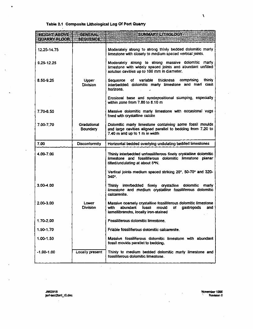
Table 2.1 Composite Lithological Log Of Port Quarry
12.25-14.75 Moderately strong to strong thinly bedded dolomitic marlylimestone with closely to medium spaced vertical joints.
9.25-12.25 Moderately strong to strong massive dolomitic mar1ylimestone with widely spaced joints and abundant unfilledsolution cavities up to 100 mm in diameter.
8.50-9.25 Upper Sequence of variable thickness comprising thinlyDivision interbedded dolomitic marly limestone and marl clast
horizons.
Erosional base and syndepositional slumping, especiallywithin zone from 7.80 to 8.10 m
7.70-8.50 Massive dolomitic marty limestone with occasional vugslined with crystalline calcite
7.00-7.70 Gradational Dolomitic maly limestone containing some fossil mouldsBoundary and glim e cavities aligned parallel to bedding from 7.20 to
7.40 m and up to I m in width
7.00 Disconformity Hoizontal bedded overlying undulating bedded limestones
4.00-7.00 Thinly interbedded unfossiliferous f sling,e dolomiticlimestone and fossiliferous dolomitic limestone planartilted/undulating at about 5°N.
Vertical joints medium spaced striking 200, 50-70° and 320-340m. -
3.00-4.00 Thinly interbedded finely crystalline dolomitic mar1ylimestone and medium crystalline fossiliferous dolomiticcalcarenite.
2.00-3.00 Lower Massive coarsely crystalline fossiliferous dolomitic limestoneDivision with abundant fossil mould of gastropods and
lamellibranchs, locally iron-stained
1.70-2.00 Fossiliferous dolomitic limestone.
1.50-1.70 Friable fossiliferous dolomitic calcarenite.
1.00-1.50 Massive fossiliferous dolomitic limestone with abundantfossil moulds parallel to bedding.
-1.00-1.00 Locally present Thinly to medium bedded dolomitic marly limestone andfossiliferous dolomitic limestone.
J396291B aNivewar 1996jorf4sMintO.doc Revsbon 0
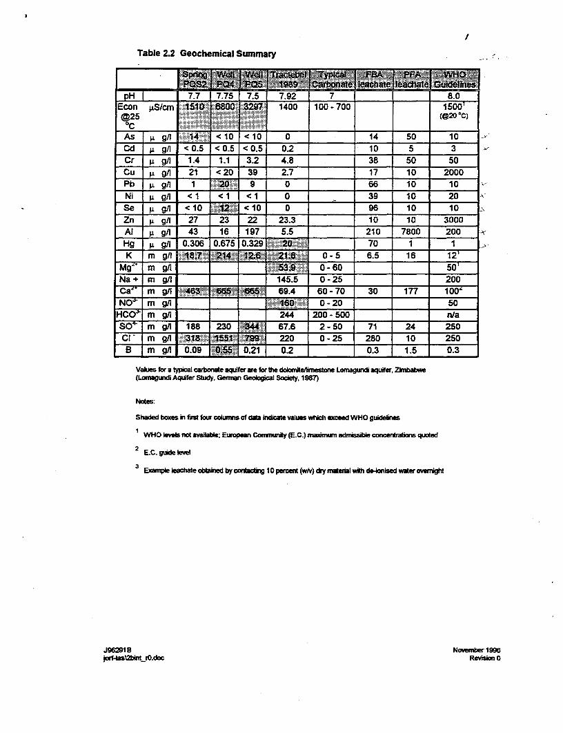
Table 2.2 Geochemical Summary
;~~ D-
pH { | 7.7 7.75 7.5 7.92 7 _ | 8.0Econ gSlcm ISIO .88.0.297 1400 100 - 700 150t-@25 (@20 OC)OC _ _ __,. __As gA 14 <10 <10 0 14 50 10Cd g gA < 0.5 < 0.5 < 0.5 0.2 10 5 3 -
Cr i gA 1.4 1.1 3.2 4.8 38 50 50Cu j gA 21 < 20 39 2.7 17 10 2000Pb F 9/ 1- 20 9 0 66 10 10Ni 1 gA <1 <1 < 1 0 _ 39 10 20Se g gA <10 c <10 0 96 10 10Zn Lg gA 27 23 22 23.3 10 10 3000Al p gA 43 16 197 5.5 210 7800 200Hg g g/l 0.306 0.675 0.329 70 1 1K mg/A 214 2 21. 0-5 6.5 16
m gA 0 - 60 50_Na + m gA 145.5 0 - 25 2007 i mg 9 46 69.4 60 - 70 30 177 100'iir m gA= 1 O - 20 50HCO mgm gA 244 200- 500 _n/a
SO- m gA 188 230 67.6 2 - 50 71 24 250ClF m gA 220 0 - 25 280 10 250B m g/A 0.09 0.21 0.2 _ 0.3 1.5 0.3
Values for a typical cawbonae aquifer are for ft doloniterhrestone Lomagundi aquifer, Zinbabwe(Lomagunri Aquifer Stidy. Gemian Geological Society. 1987)
Notes:
shaded boxes in fis four cokumns of daba hdicate vaiues which exceed WHO guildeines
YWHO Wves not avaabl; Euean C aomunty (E.C.) maidnu admissble conenors quoted
2 EC. guide level
3 Ewnpble eachate obaied by contg 10 percert (whv) drymaterial with de-nsed water oveght
J96291B November 1996jotf-ISSl2blastiO.doc Revision 0

Table 3.1 Monthly Total Rainfall For Safi
1986 20.3 17 41 12.7 0 2 0 0 0.3 4 26 0.9 124.21987 31.1 39.2 4.4 11 1.6 0.3 0 0.6 4 16.5 56.6 148 313.31988 157 23.7 32 4.3 24 8.3 0 0 0 11.4 203.4 4 468.11989 80 29.9 27.4 42.1 1.2 0 0 0 0.3 38.9 152.8 110.2 482.81990 26 2 22.8 56 10.2 3 0.4 0 0 24 25 140 309.41991 13.4 69.4 105.1 0 0 0 0 0 0 0 0 0 187.91992 0 0 0 41 1.2 12.7 0 0.9 0 57.3 5 45.1 163.21993 30 31.5 61.5 16.7 8.5 0 0 0 0.4 112.6 109.9 6.8 377.91994 47.7 62.1 16.6 1.1 11.5 2 0.9 0 0 31.2 16.5 20.2 209.81995 0.1 35.1 40.7 22.8_ 0 0 0 1 3.3 13.2 32 154.5 302.7
Average 40.56 30.99 35.15 20.77 5.82 2.83 0.13 025 0.83 30.91 62.72 62.97 294
Monthly totals t mlliietres caculated from 24 hour totals (0600 hrs to 060 hts) pvde by UKMeteorohgical Office.
J96291B Novenw 1996jorflasX2b1t_rO.doc Revision 0
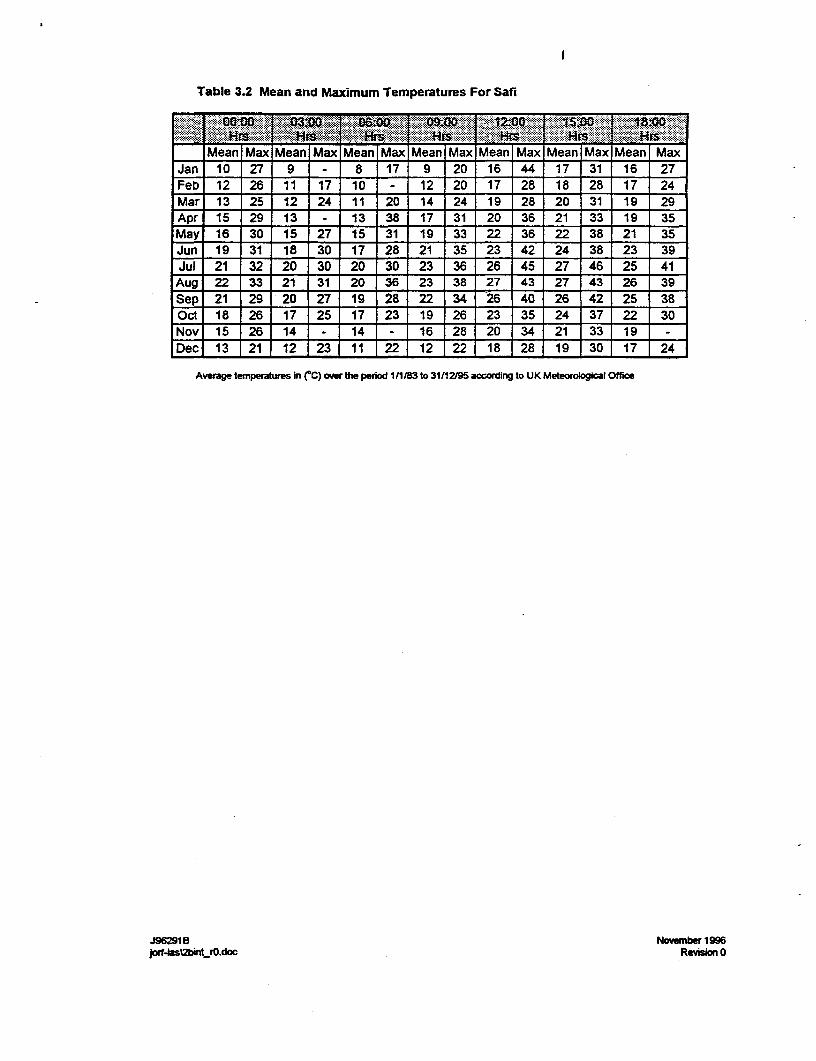
Table 3.2 Mean and Maximum Temperatures For Safi
Mean Max Mean Max Mean Max Mean Max Mean Max Mean Max Mean MaxJan 10 27 9 - 8 17 9 20 16 44 17 31 16 27Feb 12 26 11 17 10 - 12 20 17 28 18 28 17 24Mar 13 25 12 24 11 20 14 24 19 28 20 31 19 29Apr 15 29 13 - 13 38 17 31 20 36 21 33 19 35May 16 30 15 27 15 31 19 33 22 36 22 38 21 35Jun 19 31 18 30 17 28 21 35 23 42 24 38 23 39Jul 21 32 20 30 20 30 23 36 26 45 27 46 25 41
Aug 22 33 21 31 20 36 23 38 27 43 27 43 26 39Sep 21 29 20 27 19 28 22 34 26 40 26 42 25 38Oct 18 26 17 25 17 23 19 26 23 35 24 37 22 30Nov 15 26 14 - 14 - 16 28 20 34 21 33 19 -
Dec 13 21 12 23 11 22 12 22 18 28 19 30 17 24
Average temperatures in (C) ower the period 1/1/83 to 31/11295 accordirg to UK Meteorobgical Office
J96291 B November 1996jorf4Iasbirk_rO.doc Revision O
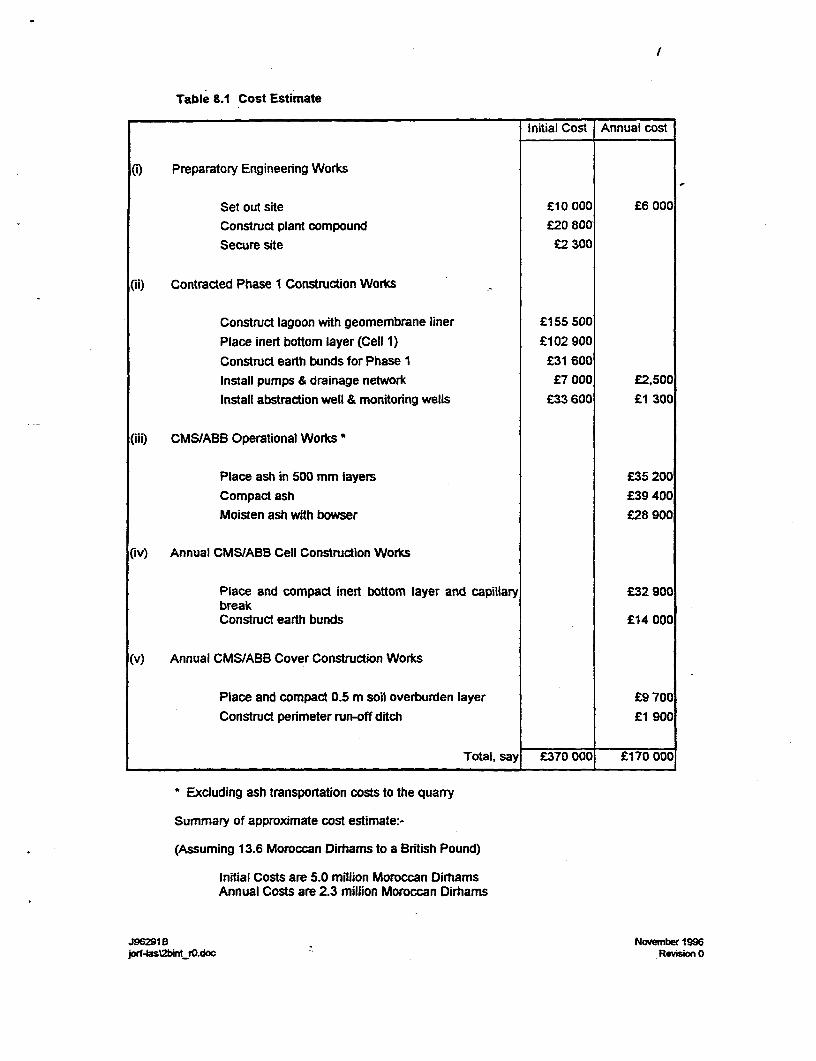
l
Table 8.1 Cost Estimate
Initial Cost Annual cost
(I Preparatory Engineering Works
Set out site £10 000 £6 000Construct plant compound £20 800Secure site £2 300
CiH) Contracted Phase 1 Construction Works
Construct lagoon with geomembrane liner £155 500
Place inert bottom layer (Cell 1) £102 900
Construct earth bunds for Phase 1 £31 600Install pumps & drainage network £7 000 £2,500Install abstraction well & monitoring wells £33 600 £1 300
(iii) CMS/ABB Operational Works *
Place ash in 500 mm layers £35 200
Compact ash £39 400Moisten ash with bowser £28 900
(Iv) Annual CMS/ABB Cell Construction Works
Place and compact inert bottom layer and capillary £32 900breakConstruct earth bunds £14 000
(v) Annual CMS/ABB Cover Construction Works
Place and compact 0.5 m soil overburden layer £9 700
Construct perimeter run-off ditch £1 900
Total, say £370 000 £170 000
* Excluding ash transportation costs to the quarry
Summary of approximate cost estimate:-
(Assuming 13.6 Moroccan Dirhrams to a British Pound)
Initial Costs are 5.0 million Moroccan DirhamsAnnual Costs are 2.3 million Moroccan Dirhams
J96291B November 1996jorf4as2btrO.doc Revision 0


FIGURES
J96291 B November 1996prf-asOk_fO.doc Revision

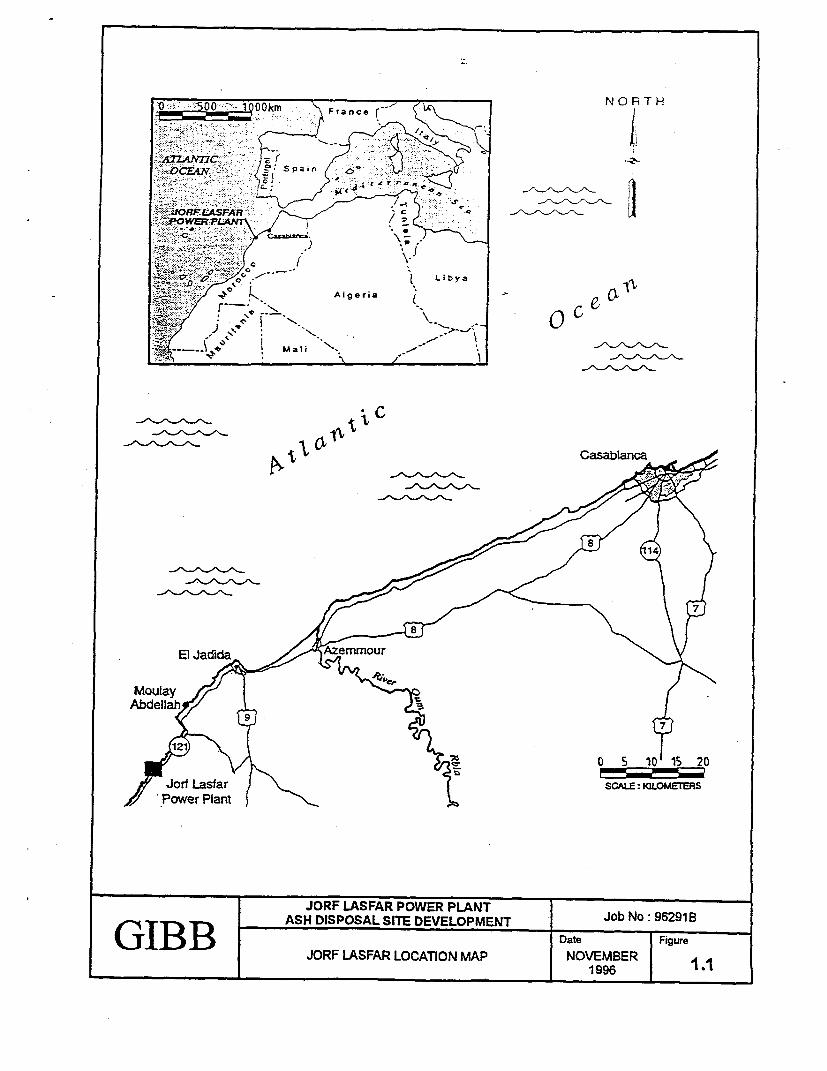
II~~~~~~~~~~~~~~JOFrance r POE PLN o
... ~~AS DISPOSA SITE DVLOPEN Jo No 921B
LibyaASFAR LCi MA OE
_________ 1996Algeria o 1
MaliC
X
El Jaaid \ri\t
Moulaty nz 1Abdellaht
br 5\/ t O~~~~~~~~~~~~ 5 10 15 20
5t Jorf sfar < [ ~~~~~~~~~~~SCALE: KLOMETERS
JORF LASAR OE LN o o 69GIB B ~~~ASH DISPOSAL SITE DEVELOPMENT JbN 69
JORF LASFAR LOCATION MAP NOVEMBER
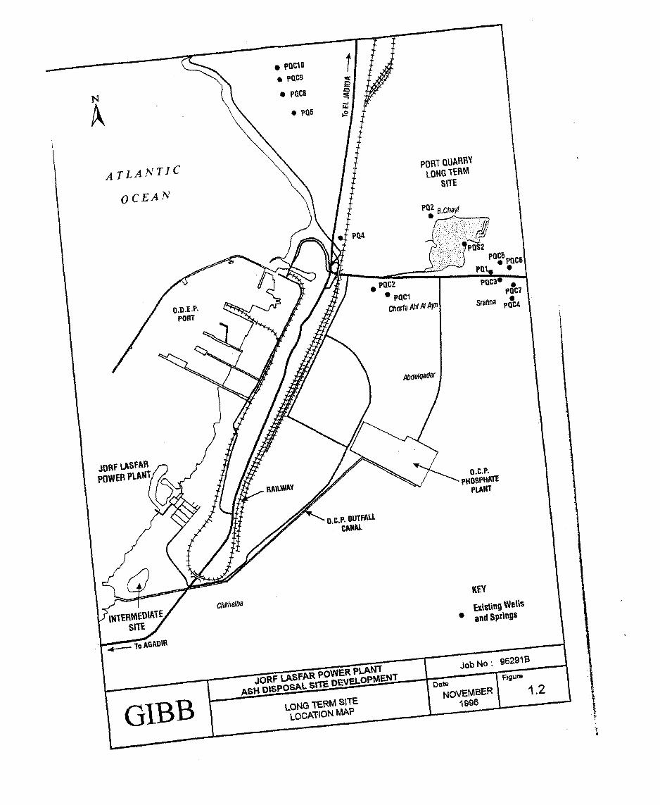
( ( PDC1
t | / j
il~~OWtQUPRB
e PQCS~~~QC
t4 . X * pa5 0
* CO~~~~~~~~~~~~~~~~~~~~~I
C EA
p
|W
IT
/ O.D.E.P. t v
//,,
~~~~~~~~~Chor.feAhl AYf
Srahfl ou
l /XtE m
N I
C
CXN,-TR
LA
/
stAbdelqader
Xi~~~~~~~~~~~~~~~~~~~pc J/ \
| ,9fiFLASFAPIXt
<pH05iN
A¢
\/ 1H1AT
X 4 it iW
/ . CANAL
\ \~~~~~~~~~~LAN
jovif LPSPADR
O.CC
Tp;W= PLATE
=-1siiTKEYCOMM,'
~~~~~~~~~~~~~,~1gWells
I 'To AGAD,
and SPriflgsITE~~~~~~~~~~~~~~~~~~~~~~~~~~~~~~~~~~~~~~~~~~~~~~~~~~~~~
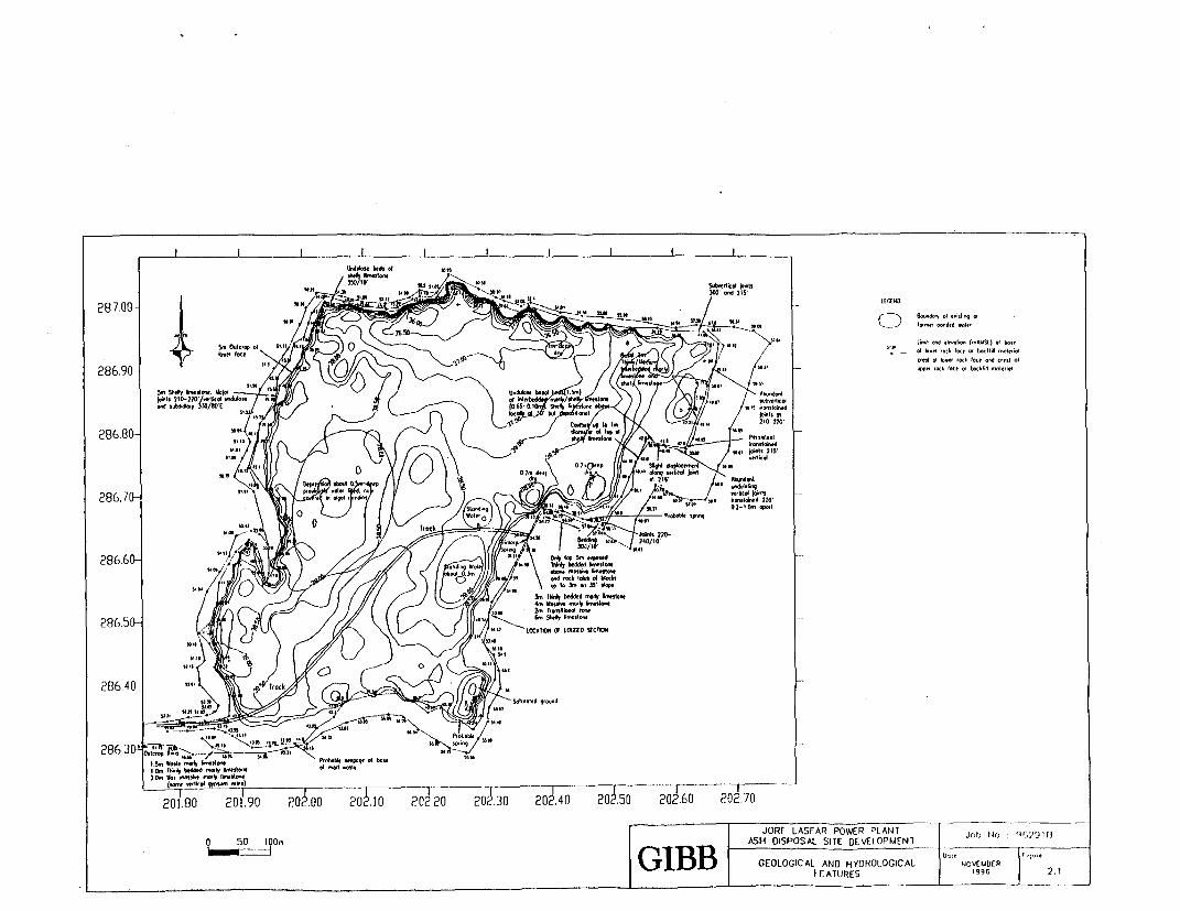
350
287.0- ttcNo0
l~~~~~~~~~~~~~~~~~~~~~~~~~~~~~~~~~~~~~~~~~~~~~~. p., M. l l l
O.W" .1 L. d '.1-t- (,,,WSA)L o
+ 861j .1 W.": S _.6 f ,,,I,0o286.90'
o. "oc
oc b o_oo
Ist 210-220'/k.1tk WA4to- of bif Sobldty 330/SO1 CO d wl"
Cottt, oS to 0~~~~~~~~~~~ 210- 220'
286.60- LI IN, m
WM
286.705 =1kd 2h0'
201.80 201.90 202.00 202.10 202.20 202.30 202.40 20,6.50 202.60 202.708 6iOO JOjRf LASFAR POWER PLANT Jobc '3f,:91[3
G.1IBBJ GEOLOGIC AL AND HYD ROLOG IC AL NOVtIUt3ER 2.
.~~~~~~~~~~~~~~~~~~~~~~~~~~~~~~. .k Id of .____
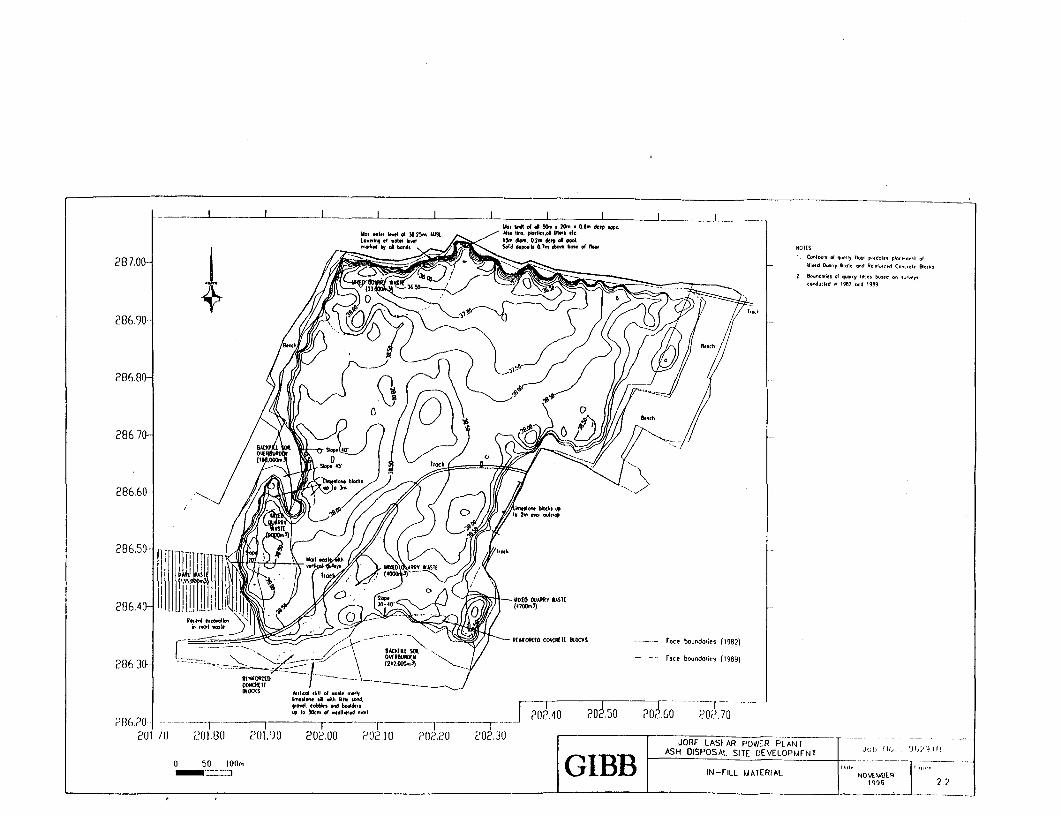
_I I L I I I _ I I _ U., k m ii S... so.. 04.o d.p "P..
Uo. .. I|.k .5 3 _25,.. l. r. -
I I. CoIn., of q..On-k.d b .01W, Sr pq..ol ,. .dl- r. o .N0of
287.00 V. i.,d L,, Wool, nod R,mOlO,-d Co",-I, 565
od.; \ld M -952 nod (959
286.90-
286.80
286.70-
201 /0 201.80 201,90 20 .0 2025.1 20.2 ,u~ 20260 JOF0ASAR.7E0PAN
~~~~~~~~~~~~~"4k286.50 -
o 5860I30G L B I2FiL2M0EIALNOV3I
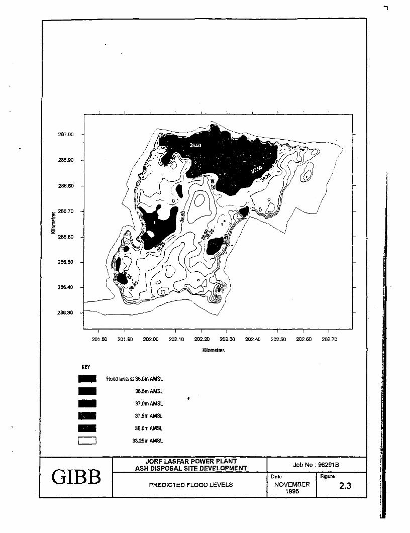
287.00 ~
I~~~~~~~~~~~~~~~~~~~~~~~~~~~~~~~~~ -
286.90 .(
286.80 0 l
286.70 -
E
286.60 F
286.50
286.400
286.30
_ I
201.80 201.90 202.00 202.10 202.20 202.30 202.40 202.50 202.60 202.70
Jilometres
KEY
Flood level at 36.Om AMSL
36.5m AMSL
37.Om AMSL
37.5m AMSL
38.Om AMSL
38.25m AMSL
JORF LASFAR POWER PLANTASH DISPOSAL SITE DEVELOPMENT JobNo:96291B
GIBBD Date FigurePREDICTED FLOOD LEVELS EMBE 2.3
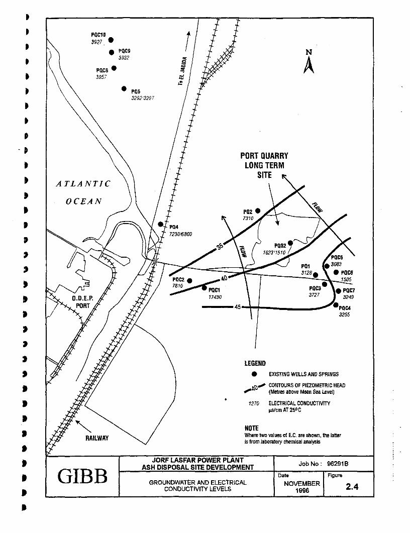
t ~~~~~POC1D | 3927 *
2O 3932 A& \ \ ~~~~3957 ;
P053292'3297
PORT QUARRY* \ \ | t LONG TERM
I \ / } SITEATLANTIC 0
< ht rD / POC2 @ \ ~PQ2
X iK O.D.E.P. X / i{/ 17430 \ { 32327 3249
{ , / g @ / 45- \ | _ 2~~~~PQC 1p250
s Y / / ~~~~~~~~~~~~LEGENDs / / SZ/ * ~~~~~~~~~~~~~~~~~EXISTING WELLS AND SPRINGS
b t2(/ !S~~~~~~~~~~~~~~~~~zo CONTOURS OF PIEZOMETRIC HEAD7?(22/ o~~~~~~~~~~~~~,b (Metres above Mean Sea Level)
( 2/ t~~~~~~~~~~~~~~~~~~~270 ELECTRICAL CONDUCTIVIT. ,j $ X \ / ps/~~~~~~~~~~~~~~~~~cm AT 250°C
s ~~~~~~RAILWAY\ Where two values of E.C. are shown, the lattert , ~~~~~~~~~~~~~~~~~~~~~~~~~Is from laboratory chemical analysis
t ~~~~~~~~~~~ASH DISPOSAL SITE DEVELOPMENT |Job No: 96291 B. ~~~GIB B GROUNDWATER AND ELECTRICAL NOVEMBER b ~~~~~~~~~~~~~CONDUCTIVITY L-EVELS 1996 | 2.4
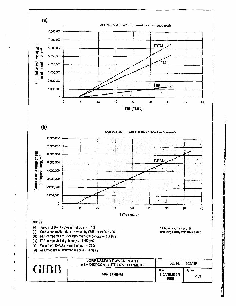
(a)ASH VOLUME PLACED (Based on all ash produced)
8,000,000 I
7,000wo-T
, 6,000,00 -,l
. 2,000,000- . | FBA _ _
A2 ,000,000 |>_ -
0 _ _ _ _ _ _l _. _
0 5 10 15 20 25 30 35 40
Time (Years)
(b)ASH VOLUME PLACED (FBA excluded and re-used)
8,000,000 = ==
7,000,000
6,000,000
E
> 0050
NOES
1,000,000
0 5 10 is 20 25 30 35 40
Time (Years)
NOTES:(i) Weight of Dry Ash/weight of Coal 11% * FBA re-used trom year 10,(ii) Coal consumption data provided by CMS tax of 9-10-96 increasing linearly trom 0% in year 5
(iii) PFA compacted to 95% maximum dry density = 1.5 tUm3
(iv) FBA compacted dry density = 1.45 tIm3
(v) Weight of FBAJtotal weight of ash = 20%(vi) Assumed lIfe of Intermediate Site 4 years
T JORF LASFAR POWER PLANTr Tlr' 1C) ASH DISPOSAL SITE DEVELOPMENT Job No: 96291 BGIBJ1 B D Date FigureI ASH STREAM NOVEMBER 4.1
____________ ___________________________1996 j .
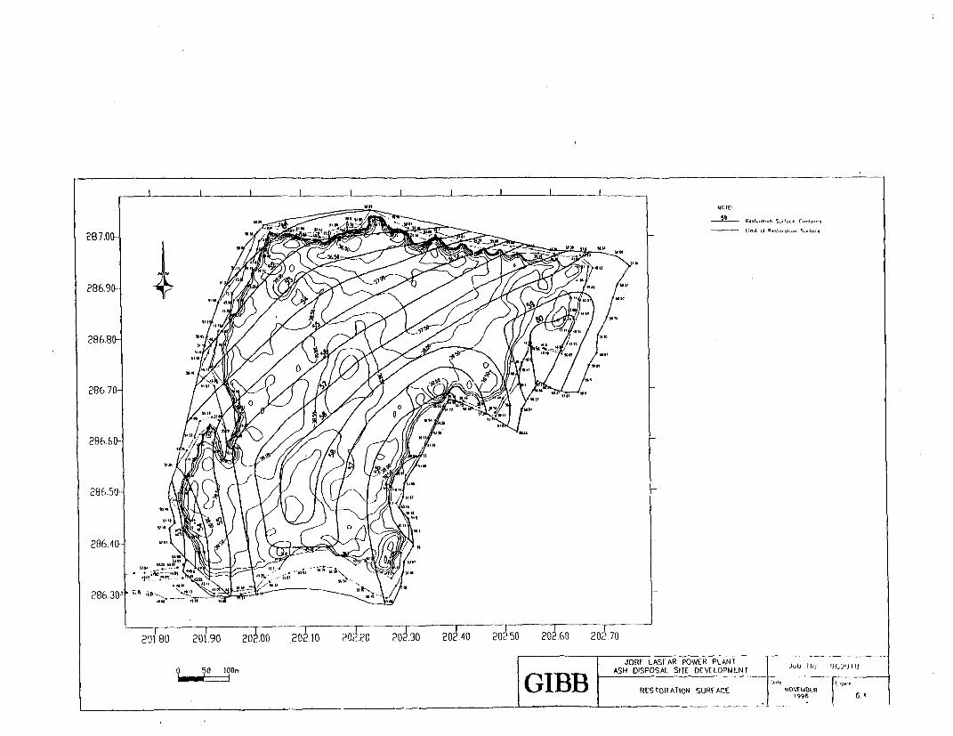
I I I I I
286.90-
28685
286640
286.350
201 80 201.90 202.00 202.10 20J20 202.30 202.40 202.50 202.60 202.70
JORF LASiAR POWER PLANT __ . . 1_0 50 lOOn ASH DISPOSAL SITE DEVELOPMENT I., 11GIBB ~~~~RESTO-RATION S~UREACE NV!1(
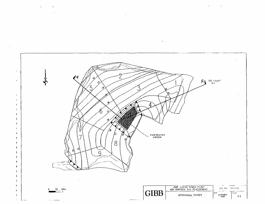
6 4
JORF LASFAR POWER PLANT o 50 GIoB ASH DISPOSAL SITE DEVELOPMENT Job_ _. _ 1 __
G IB B OPERATIONAL PHASES 9o6 ER1 6 2
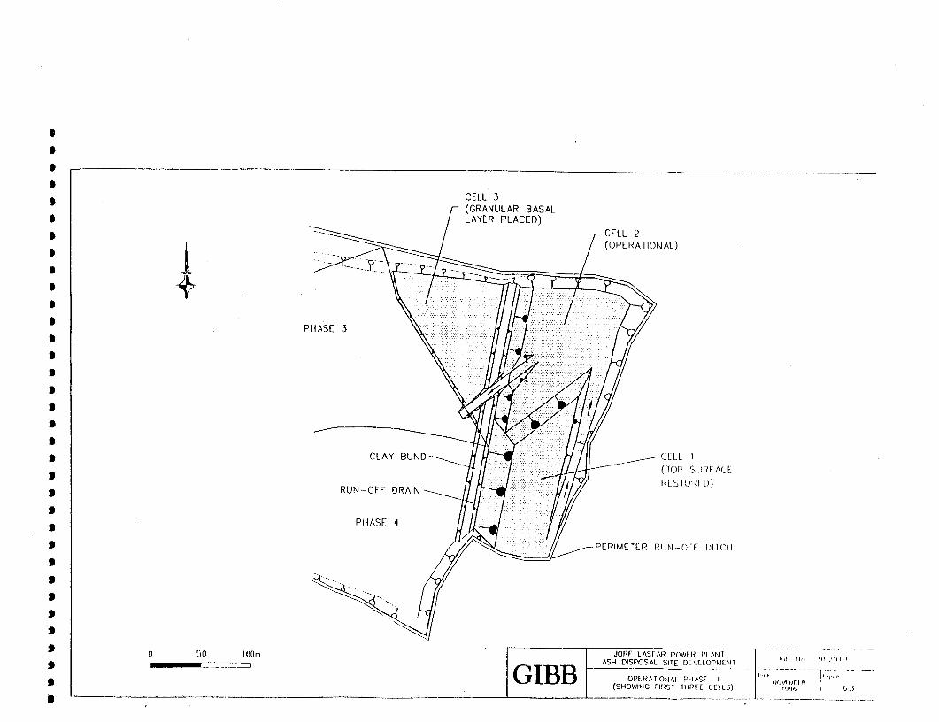
S
CELL 3(GRANULAR BASAL
* / ~~~~~~~~~~~~~~~~LAYER PLACED)/ r ~~~~~~~~~~~CELL 2
OI- = U = B = I / (OPERATIONAL)
PHASEE 3 ... . E111 I E 1\ w
s~ ~ ~ ~ ~ ~ ~ ~ ~ ~~~~HS PHS4 :-i0 ;;00 ;2 t0;000 f ;; :i
fi~~~~~ 50 100:;: jOR LASFAR- F:'50 AN "h0. II,, 0;;t X
s~~~~~~~~~~~~~~~~~~~~~~~~~GB OIERTINA PIAS Ioi..,'': k," :::S Pic1 ::t1
J -t- 11: :1 i :0 i : / g (TOPS IURECSE
* |. ;|::,i00a CTIF)J U-F R I|S0 ; 0 /S 1 : - /9 SE4 z S X \ PRMTRrJ r )II
S C-LL 11
tJ >~~ERMEL OPUNATIONFL P)t SIIXvlvl3~~~~~SOIGFRIIlR EL)8( 3
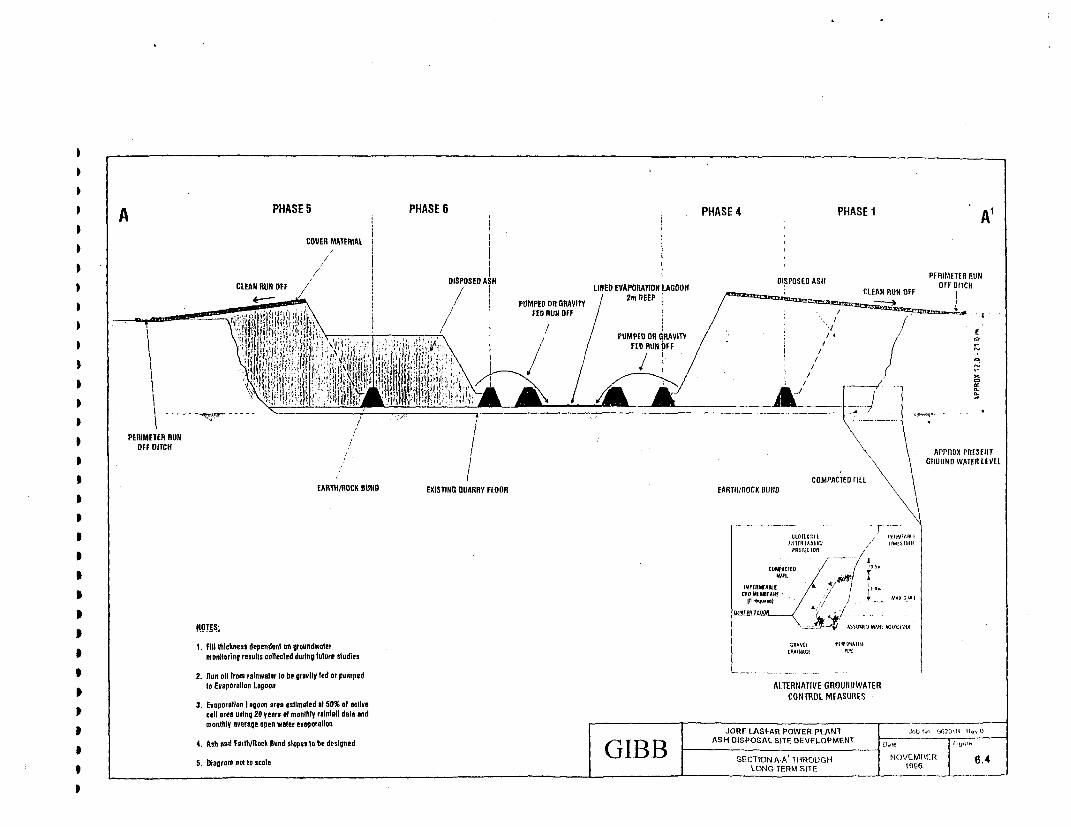
* A PHASE5 PHASE 6 PHASE 4 PHASE I ACOVER MATERIAL
DISPOSED AS" DISPOSED ASII PRM1 U* CLEAN RUN OFF / LINED EVAPORATIN AGOON D H
3 8 | \ \ ..... GnnuN~~~~~~~~~~~~~~~~~~~~~~~~~~~FD RATEn iOEVE
*~~~~~~~~~~~~~~~~~~~~~~~~~~~~~~~~~~~~PME ORpclDl ERA\ T
3 ~~~~~~~~~~~~~~~EAFItH/ROK BOND EXIStiNG QUARRy FLOOR EARTH/ROCK OUND\
* __- - - -_
3~~~~~~~~~~~~~~~ ~ ~ ~~~~~~~~~~~~~~~~~~~~~~~~~~~~~~~~~~~~~~ tolE ft x IR V No IFAM#lI I
* PEIEE RUN J t Ml W
OFF ITCH . APPX PRSETAOUtWlDI
1Fill thlck(ness dependent tni gtoundwaler [ie^vO I-Wooll* ~~~~~~~~m Dnilorinil resuills colleclkd during tulure sludies oal pwi
g ~~~~~~~~2. nun oll Irom ralnwaler lo be grawvlly led or pumpedto Ev*porallon Lagoon Al TERRATIVE GWOUNWATER
( CONTFiOLMCEASURES3. Evaporallon i ogoon otes esimaled al 50% of cilvre
t ~~~~~~~~~~cell ores uslng 20 years of manthly ralnfnll data and3 ~~~~~~~~monthly average open wrater evraporation JORF LASFAR POWER PLANT J.bIV4, 9627f311 11-0
t ~~~~~~~4. Ash and EarlhlRock Eund slopes lo be designed GIB BASHt DISPOS AL SITE Dt-VELOP MENT X j , .,,
.S Diagram nolDto scale lB BSECTIONIAA'THRHG I E N A NOVR OOC 34 N
I~~~~~~~~~~~~~~~~~~~~~~~~~~~~~~~~~~~~~~~~~~~~~~~~OI EMST
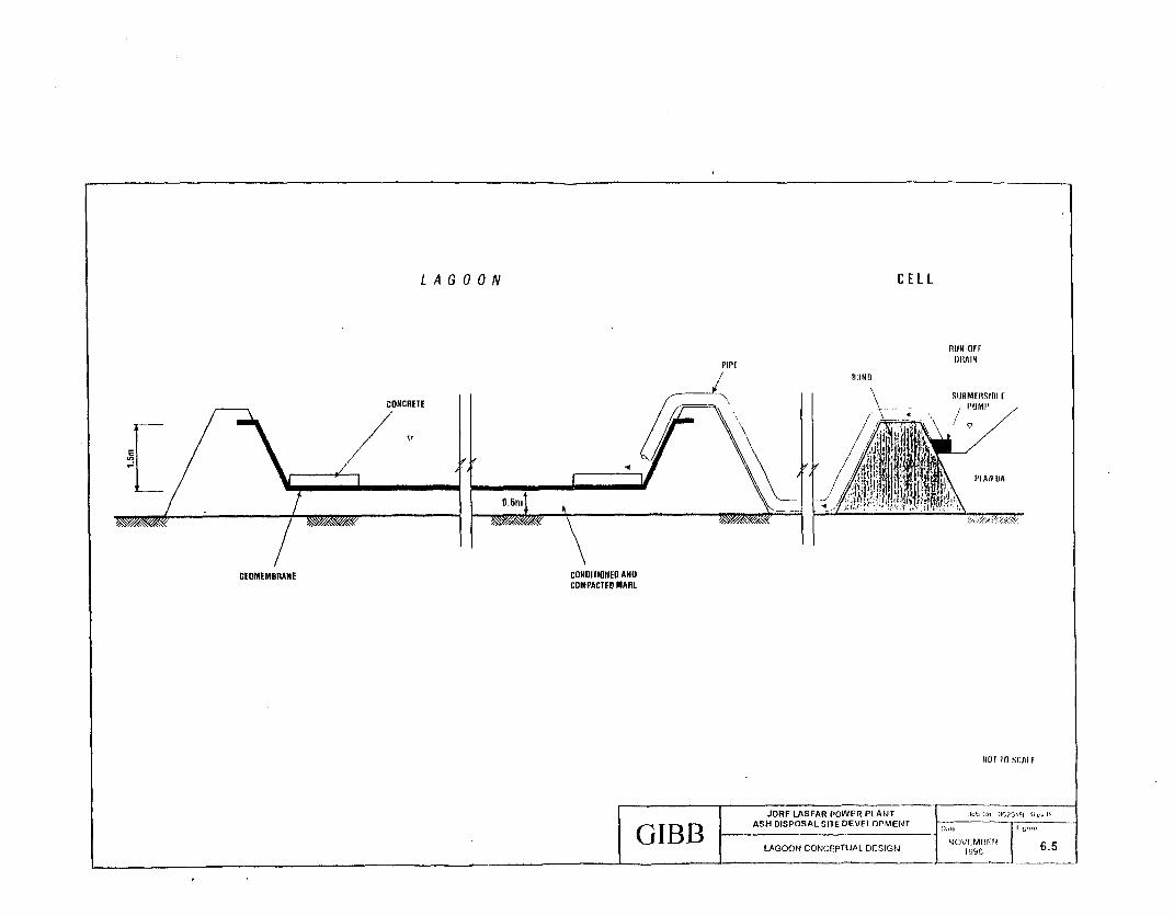
L A G OO N CELL
RUN OFr
PIPE (RAIN/ ~~~~~~BUND
JSUBM IIISIRL ICnNCRETE / A ' / MI'
X , X ~~~~~~~~~~~~~~~~~~~~~~~~~~~~~'II AK~I
GEOMEMBRANE cONDITIONEO ANDCOMPACTE0 MARL
iDf In SCAI F
r . til9t) ~~~~~~~~~~~~~LAGOON CONCEPTUAL DESIGN OMlE ...... 65
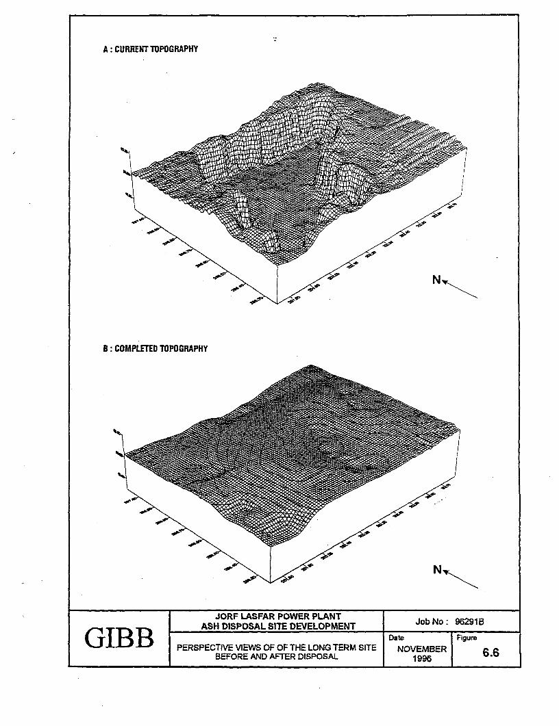
A: CURRENT TOPOGRAPHY
eP,
B: COMPLETED TOPOGRAPHY
N
T IJORF LASFAR POWER PLANTASH DISPOSAL SITE DEVELOPMENT Job No: 962918GIBBDaeFgrj PERSPECTIVE VIEWS OF OF THE LONG TERM SITE NOVEMBER
_ AND AFTER DISPOSAL 1996
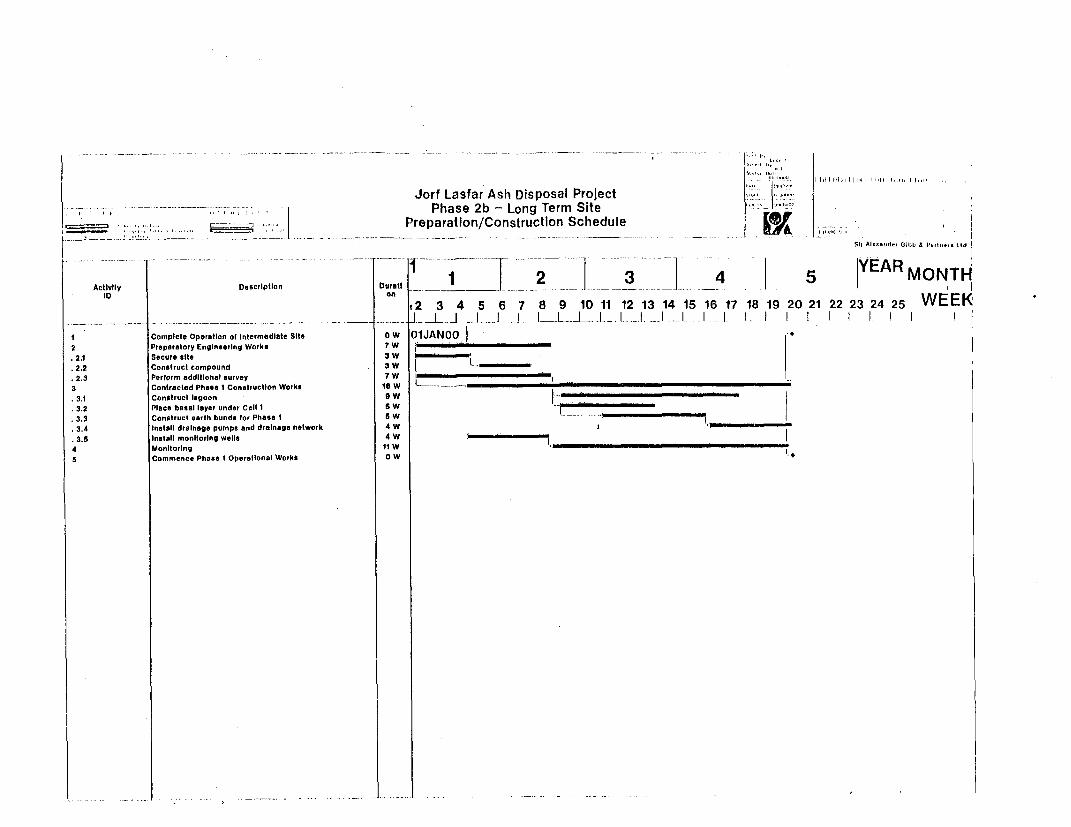
Jorf Lasfar Ash Disposal ProlectPhase 2b - Long Term Site ,
,,_____1,,, t-_ fi^^> | Preparation/Construction Schedule L.JSi, Al ... .,,l A,. a . .. L, Id
_ ._ o _ _-- --- -------- -1-- - -- ...... tYEAR1 | 2 | 345 nMOTActivily Description Durati W EE2 3 4 5 6 7 8 9 10 11 12 13 14 15 16 17 18 19 20 21 22 23 24 25 WEEK
_ _ . . . .. .. _ . _ . _ _ _ _ ............... .. _ J .. . J__I. I. .I__L L A. I.L_I .I. I. . I 1 1 I 1 I 1 1 1I Complete Operation ot Intermediate Site ow 01JANOO|2 Preparatory Engineerlng Works 7 W21 Secure site 3W2.2 Construct compound 3W W2.3 Perform additional survey 7 W
3 Contracted Phase I Construction Works 8 Ww3.1 Conotruct lagoon 9 w3.2 Place basal Isyer under Cell 1 5 W3.3 Construct earth bunds for Phase i S W3.4 Insteit drainage pumps and drainage network 4 W3.5 Insthll monitoring wells 4 W
4 Monitoring t1 W5 Commence Phase I Operasionai Works 0 w
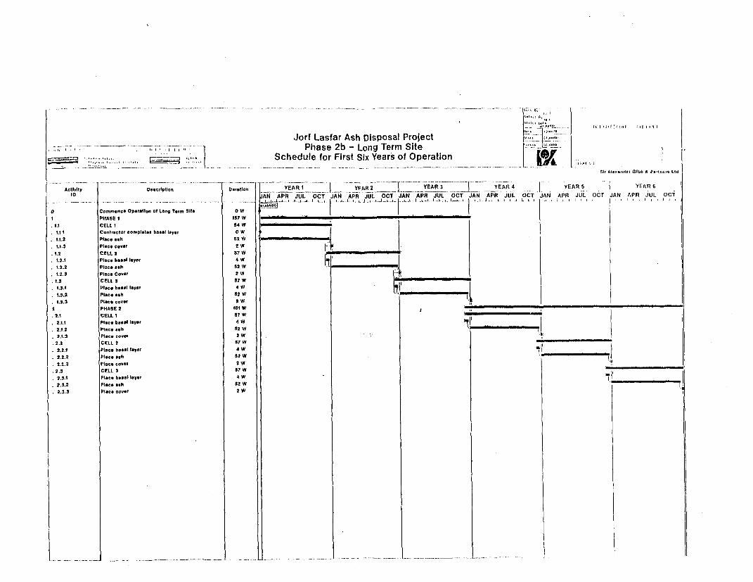
Jorf Lasfar Ash Disposal Project I_ Ilj.lHL- ~~~ I Phase 2b - Long Term Site f..I
, ~ ---- ,. | .Schedule for First SixYearsof Operation
Si, Al-evzdv, GIbb a Po,iv,-. Ltd
Activity O.ucriplivrr o~ocuatov __ ERIy~R __ YERi Y EAR 4 YEARSYAR
OtoeT tON DU.,TIr, IAN APR JUL OCT JAN OCT JAN APR JUL OCT JAN JUIL OCT- JAN APR JUL OCT JAN A
O Commence Operation o0 Long Term Site W _PHASE I 157 W
IA tCELL 1 54 W* 1.1.1 Contractor complote bOial loyer OW* 1.1.2 Piece ash 52 W* 1.1.3 Place cover 2 W
1.2.1 Plce baece layer 4 W.12.2 Place ash 52 W _______i__
1.2.3 Plce Covor 2 W I1.3 CELL 3 57 W1.3.1 Plece bstl laysr 4 W1.3.2 Place ash 52 W l _1.3.3 Piece cover 2 WI
2 PHASE 2 1le w2.1 CELL 1 57W icI2.1.1 Place bosit layer 4 W2.1.2 Piece eeh 52W I _
2.2 CELL 2 67W '2.2.1 Plce boeal layor 4 W2.2.2 Place ash 62 W2.2.3 PlIce covet 2 W
2.3 CELL 3 57 W2.9.1 Piece boes layer 4 W2.3.2 Place ash 52 W2.2.3 Pi_eccover 2 W

I
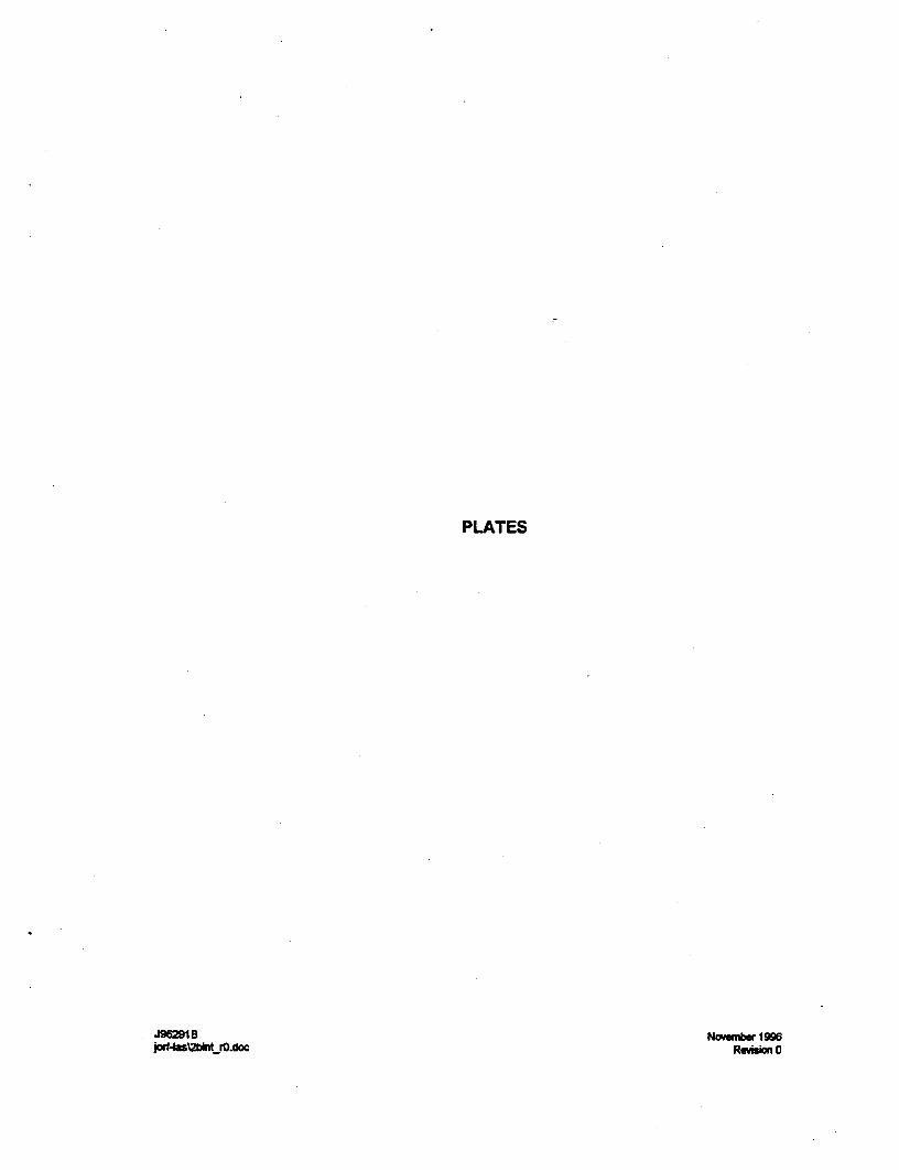
PLATES
J96281 B November 19964s2binrdrO.doc Revision 0

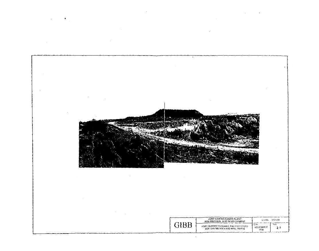
-~ -. -
w:o 1El t *'* *&.'-
I~~I
JORF LASFAR POWER PLANT 961 91'1ASH DISPOSALSITE DEVELOPIMENT ib - Jb291, -
'J1 D |~ " DOL OQUARRY LlIRANCE ANNQIO-WAITI1 2F 1SOFL OVFRBUROEN~ AND MARL WASlE NOFN_ .
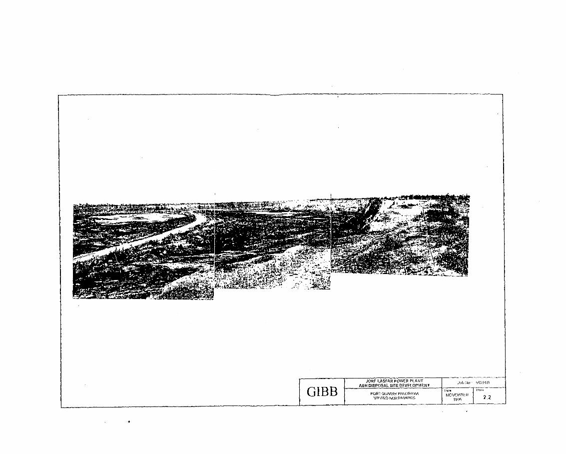
JORF LASFAR POWER PLANqT
T ~~~ASHA DISPOSAL SITE DEVELOPMENT
G I B 1 PORT QUARRY PANORAMA NOVEMiBER 2VAEWE.D NORTHWARD 16 2
*~__
-r
I
JORF LASFAR POWER PLANTJoN:921GIB B ~~~ASH DISPOSAL SITE DEVELOPMENTJoN:921
&~ ~G B BACKFILLED SOIL OVERBURDEN ON NOVEMBER__ ~~~~~~WESTERN SIDE OF QUARRY 1996 2.3

JORF LASFAR POWER PLANTJoN:921ASH DISPOSAL SITE DEVELOPMENT Job : 291B
GIBB LOGGED SECTION OF LOWER NOVEMBERAND UPPER QUARRY FACES 1996 2.4
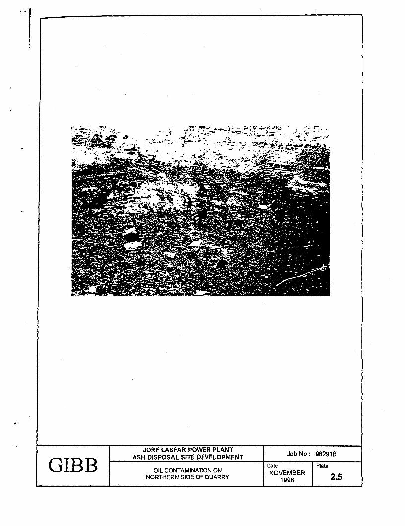
-~~~~ -
- ~~~~~~~
JORF LASFAR POWER PLANTASH DISPOSAL SITE DEVELOPMENT Job No: 962918GTBB Date PlateG IBB . ._A_OIL CONTAMINATION ON DatEMBER
NORTHERN SIDE OF QUARRY NOVEMBER 2.51 9962.
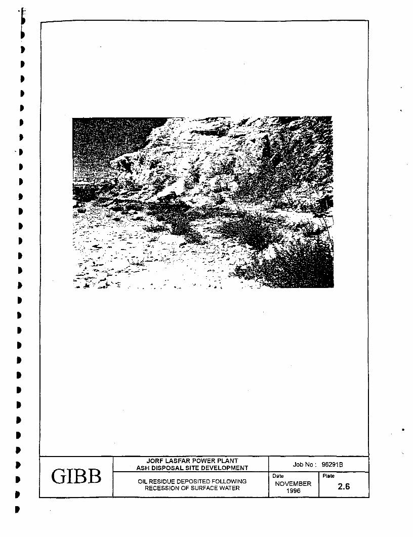
I~~~~~~~~~~~~~~~~~-w
p~~~~~~~~~~~~~~T
p~~~~~~~~OFLSA OE LN oN:921I~~~~~~~S IPOA I EEOMN
I~~~~~~~~~~~~~~~~~~~Dt itGI BOLRSDEDPSTDFLOIG NVME
I~~~~~~~~EESO FSRAEWTR19 .