&/p,/ca - ibiblio.org specification for... · guidance navigation date &/p,/ca milton b....
TRANSCRIPT

GUIDANCE NAVIGATION
Date &/p,/ca MILTON B. TRAGESER, %RECTOR APOLLO GUIDANCE AND NAVIGATION PROGRAM
-ate ~,,/q,/dL FORREST E. HOUSTON, ASSOCIATE DI ECTOR
INSTRUMENTATION LABORATORY
pproved f o r NASA
E. J. Hal l J. Mi l l e r , J. Aronson
A. La t t anz i Au p st 19 6 2
1 N S T R U M E N TAT I 0 N L A 6 0 R AT 0 R V-# a*
5 - 1 *; i
CAMBRIDGE 39, MASSACHUSETTS
COPY# 3-9 OF ''SOPIES THIS DOCUMENT CONTAINS 3t PAGES

ACKNOWLEDGEMENT
This report was prepared under the auspices of DSR Project 55-191, sponsored by the Space Task Group of the National Aeronautics and Space Administration through Contract NAS9 -103.
This document contains information affecting the na'ional defense of the United States within the meaning of the Espionage Laws, Title 18 , U . S. C . , Sections 793 and "b4, the transmission o r the revelation of which in any manner to an unauthorized person is prohibited by law.

SPECIFICATION FOR
PROCUREMENT OF APOLLO INERTIAL REFERENCE INTEGRATING GYRO
INSTRUMENTATION LABORATORY MASSACHUSETTS INSTITUTE OF TECHNOLOGY
TABLE O F CONTENTS
Page - Section Ti t le 1. S C O P E . . . . . . . . . . . . . . . . . . . . 5
2 . APPLICABLE DOCUMENTS. . . . . . . . . 5
3 . REQUIREMENTS. . . . . . . . . . . . . . 6
4. QUALITY ASSURANCE PROVISIONS . , , . 12
5. P R E P A R A T I O N F O R D E L I V E R Y . . . . . . 29
6 . N O T E S . . . . . . . . . . . . . . . . . . . 29
3
SPEC IFIC A TION FOR
PROCUREMENT OF APOLLO INERTIAL REFERENCE INTEGRATING GYRO
INSTRUMENTATION LABORATORY MASSACHUSETTS INSTITUTE O F TECHNOLOGY
1. SCOPE
1. 1 Scope of this Specification
This specification establishes the requirements for the
procurement of the Inertial Reference Integrating Gyro (MIT /IL C-95799) (hereafter called the IRIG) designed for use in the
Apollo Guidance and Navigation System.
2. APPLICABLE DOCUMENTS
2. 1 Specifications for the Production of IRIGs
2. 1. 1 MIT/IL SDecifications
MIT/IL drawing (2-95799 and those drawings which a r e referenced by it and its subassemblies, together with appropriate par ts l ists and the MC specifications (MIT /IL document E- 1091)
define the gyro design for this specification. Report R-349, as applicable to the gyro, specifies the Reliability and Quality Control
program.
2. 1. 2 Government Specifications
NASA Quality Assurance Documents 200-1, 200-2 and 200-3.
2. 2 Conflicting Requirements
In the event of conflict between the requirements of the contract, this specification, and other specifications and drawings
5

cited herein, the requirements of the contract, this specification, and the documents listed in this section, shall govern, in that or der.
2. 3 Procurement of Applicable Documents ~ ~~
Copies of specifications, standards, drawings, and publications required by the contractor in connection with specific procurement functions should be obtained from MIT /IL.
3. REQUIREMENTS
3 . 1 General Requirements
3 . 1. 1 Materials
The materials used in fabricating the IRIG shall be in strict accordance with applicable drawings and specifications referenced in section 2.
3 . 1. 2 Construction and Assembly
The construction of the IRIG shall be in strict accordance with applicable drawings and specifications referenced in section 2.
3. 1. 3 Workmanship
The fabrication and finish of the IRIG, its assemblies, subassemblies, and parts shall be such as to produce a unit free from any defect that would affect proper functioning in service.
3 . 1.4 Serial Numbers
Each IRIG shall be identified by a ser ia l number assigned by the NASA. Vendors shall request assignment of ser ia l numbers from the procuring activity.
Unauthorized use of NASA ser ia l numbers other than those issued by the NASA is prohibited.
3. 1. 5 Interchangeability
Unless otherwise specified, the IRIG and its component parts shall be physically and functionally interchangeable without
selection o r fitting within the tolerances of this specification.
6
3. 1. 6. Service Life
3. 1. 6. 1 Operating Life
The IRIG design is intended to meet performance specifications for at least 5000 hours of gyro wheel operation,
including the manufacturer's turntable testing time of the completed unit.
3. 1. 6 . 2 Shelf Life
The IRIG design is intended to have a shelf life at least three years, without operation, at ambient room tem- peratures after final acceptance at the vendor's plant.
3. 1 . 7 Reliability
This section is inserted to provide for the inclusion of future reliability considerations a s they may occur. The present known objective for the reliability of stable drift characteristics of gyros covered in this specification is three years.
3. 2 AcceDtance Tests
3 . 2 . 1 Classification of Acceptance Tests
The Acceptance Tests a r e to be performed on all IRIG's being submitted for acceptance under the contract. Acceptance Tests shall be performed by the manufacturer and may be witnessed by an MIT/IL Representative, an authorized Representative of MIT /IL, o r a NASA Representative. These tes t s a r e detailed in paragraph 4. 2.
7

Acceptance Tests are broken down into two categories as follows: Functional Tests which a r e designed to measure the functional parameters of the IRIG, and Performance
Tests which a r e designed to measure the basic performance characteristics of the IRIG a s a precision instrument.
After initial calibration and balancing the Acceptance Tests shall be made as follows (except as specified in paragraph
4. 2. 3. 4):
I
I1
Functional Tests (see paragraph 4. 2. 2)
Performance Tests (see paragraph 4. 2 . 3 )
Temperature Stability Test (see paragraph 4. 2. 3. 1)
Float Freedom Test (see paragraph 4. 2. 3. 2) 3 ser ies of Servo Tests (see paragraph 4. 2. 3. 3)
24 hour storage at 135OF 3 ser ies of Servo Tests (see paragraph 4. 2. 3. 3) Shroud 3 ser ies of Servo Tests (see paragraph 4. 2. 3. 3) 24 hour storage at room temperature 3 ser ies of Servo Tests (see paragraph 4 . 2 . 3. 3 ) Torque- Angle Calibration Tests (see para- graph 4. 2. 3. 4)
3. 2. 2 Functional Requirements
The IRIG shall perform the following functions
3 . 2 . 2 . 1 Thermistor Calibration
The d-c resistance of each thermistor shall be 345 f 34. 5 ohms at 135'F as measured per MC 25-800, current revision.
3. 2 . 2 . 2 Ducosyn Resistances
(1) Suspension Circuits: 2 1 f 3 ohms
(2) (3) Signal Generator Secondary Circuits: 65 ohms f 6 ohms (4 ) Torque Generator: 65 ohms/winding * 6 ohms
Signal Generator Pr imary Circuit: 8 ohms *O. 8 ohms
8

3 . 2 , 2 . 3 Magnetic Suspension Current Phasing
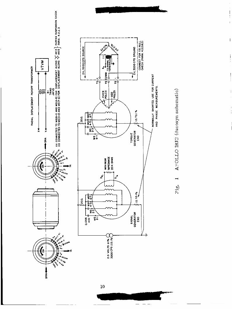
Connected as shown in F ig . 1 with each ducosyn's working capacitors (C,) equal to each other within 1 /20/0, the S. G. and T G suspension currents shall lag the 2 . Ov source by 45* 3'. This measurement shall be made with the signal generator primary disconnected and with the float suspended within the center half of the electrical range of the suspension.
3 . 2 . 2 . 4 Wheel Operation
(1) The spin motor shall be capable of reaching synchronous speed when excited with a voltage of 2 6 . 6 ~ maximum.
The spin motor shall reach synchronous speed within 90 seconds maximum after application of normal 28 v excitation
The wheel run down time shall be measured, per MC 2 5 - 8 3 4 , once at the beginning and once at the end of each servo test se r ies . The standard deviation (a ) of the run down times to 6000 rpm obtained in these tests must be less than 4. 0 seconds. (n 2 8 for determination of u ).
( 2 )
( 3 )
T
T 3 . 2 . 2 . 5 Angle - Voltage Sensitivity
The average ratio of IRIG voltage output to Input Axis (IA) Angle, near null, shall be 11. 8 f 3 . 54 mv/mr .
3. 2 . 2. 6 Input Axis Polarity
Rotation in a positive IRIG IA direction should cause the voltage from S1 to S2 to have a phase of 0' f 5'.
8 1
3 . 2 . 2 . 7 Limit of Equivalent Angular Rotation
An angular rotation of .61° to .85O about the IRIG IA from S. G. null, shall be sufficient to produce maximum angular displacement of the IRIG float about the Output Axis (OA).
3 . 2 . 2. 8 Null Voltage Measurements
3 . 2 . 2. 8 . 1 generator null voltage shall not be greater than 4mv. (Signal
Signal Generator: Without compensation, the signal
9
z 8 b n W N
I?+
W 0 f a
ah K K
r'
c: 0 *I
a P ln
10
Generator null is running and when the 3200 cps signal is zero. )
3. 2. 2. 8. 2 operated a s a signal generator shall be within 1 / 2 m r of the
signal generat or null.
Torque Generator: The torque generator null when
3. 2. 2. 9 Vibration Requirements
The IRIG shall be capable of withstanding, without
damage of any kind, 3 1 / 2 g r m s sinusoidal acceleration along each of its principal axes, sweeping from 100 to 2000 cps.
3 .2 .3 Performance Tests
3.2.3. 1 Temperature Stability Test
At normal excitation and normal operating temperature
with the OA up or down, the variation in gyro drift shall not be greater than 5 meru/'F when subjected to a temperature cycle of 3'F at a rate between 1/2OF/minute and l0F/minute.
3.2. 3. 2 Float Freedom Test
The performance requirements for the Float Freedom
Test a r e as specified in paragraph 4. 2. 3. 2.
3. 2. 3. 3 Drift Rates
With the excitation of 2 v f 170, t h e uncompen-
sated bias drift rate (NBD), shall not be greater than 10 meru at any time. The acceleration-sensitive drift rate (ADIA) due to l g of case acceleration along the positive Input Axis shall not be greater than 15meru at any time. The acceleration- sensitive drift rate (ADSRA) due to l g of case acceleration along the positive Spin Reference Axis shall not be greater than 15 meru at any time. The drift rate component proportional to the
second power of the case acceleration along any 2 axis shall not be more than 1 meru/g . (This is
inherent in the design, if the wheel is assembled
per MC 25-803, and is not a gyro test require- ment).
( 5 ) The standard deviation of the ten 1' points in any one of the four positions during any of the servo tes ts shall not exceed 3 meru.
( 6 ) The greatest difference in NBD, ADIA, and ADSRA during all drift performance testing shall not be greater than 5 meru.
3.2. 3. 4 Torque -Angle Calibration Test
The digital angle scale factor MAT/H shall be
0.012 mrad f 570 and the Command Angle Torque Rate shall be 1. l o / s e c ~ 1 0 ~ 0 .
4. QUALITY ASSURANCE PROVISIONS
4. 1 General
Unless otherwise specified herein, the supplier is responsible for the performance of all inspection requirements pr ior to submission for MIT/IL or NASA inspection and acceptance. Except as otherwise specified, the supplier may utilize his own facilities or any commercial laboratory acceptable to MIT /IL or NASA. Inspection records of the examinations and tes ts shall be
kept complete and available to MIT/IL and NASA a s specified in the contract or order.
4 . 1 . 1 Contractor's Quality Assurance Program
The contractor's quality assurance program shall be conducted in accordance with NASA Quality Assurance Documents 200-1, 200-2 and 200-3 and MIT Report R-349 to the extent specified in the procurement documents.
The Government reserves the right to perform any of the inspections set forth in this specification where such inspections a r e deemed necessary to assure that supplies and services conform to prescribed requirements.
4 .1 .2 Special Test Equipment (Test Turntable)
A special test turntable and associated equipment must be provided and must have provisions for operating the IRIG under conditions specified. Adequate meters must be provided to measure excitation levels and operating temperatures. The test
12
table must have the
(1) Suitable mounting to assure that Gyro IA is - or can be adjusted to be - parallel to the test turntable axis within 1 m r (turntable axis wobble f 0. 1 mr) .
(2) Provision for testing with the table axis vertical within 1 m r .
(3) Provision for testing with the turntable axis within 1 m r of horizontal and within 5 m r of north.
(4 ) Servo to keep gyro signal generator output signal inphase component below 2 mv and constant within . 5mv during gyro drift measurement runs.
(5) Angular velocity readout must provide timing signals for 1 degree angle increments with an accuracy of 5 seconds of angle o r better for each increment.
(6) Angle increment timing during drift measure- ment tests must be accurate to 0. 1 second
time e r r o r or better.
(7 1 Wheel supply must be capable of delivering 15 w starting power.
(8) Table angle readout for ten degree increments shall have an accuracy of 5 seconds of a r c or better for each increment.
4 . 2 Acceptance Tests
4. 2 . 1 Test Conditions
Unless otherwise specified, the test procedures shall be accomplished under the following conditions:
Operating Temperature: Flotation f 1 /2'F and stable within f 0. 1°F.
Flotation shall be 135OF f 2OF Vibration: None (see Vibration Test, paragraph 4. 2 . 2. 11)
Humidity: Room ambient to 957" relative maximum humidity
Microsyn Excitation: 2 v f 17'0 at 3200 cps*,l%.
This voltage is defined a s having 0' phase.
Suspension Excitation: 2 v f 170 at 3200 cpsf . l%
Spin Motor Excitation: 28 f 0. 28v, 800 f 0. 08 cps, two phase, A leading B by 90 50.
4.2. 2 Functional Tests
4 . 2 . 2 . 1 Thermistor Calibration Before mass balance adjustment, the IRIG thermistors
must be calibrated pe r M. C. #25 -800, current revision.
4 .2 . 2 . 2 Ducosvn Resistance Checks
The d-c resistance of each microsyn circuit must be measured with a suitable 20,000 ohm/volt ohmmeter. The resistances must be within the following limits:
(1) Suspension Circuits: 2 1 f 3 ohm at room temperature
( 2 ) S. G . Primary Circuits: 8 f . 8 ohms per leg. at room temperature
(3) S. G. Secondary Circuits: 65 f 6 ohms at room
(4) T. G. :
temp e ratur e
65 f 6 ohmslwinding at room temperature
4 .2 .2 .3 Suspension Operation Test
The IRIG is mounted in a precision test turntable and brought up to the Operating Temperature.
Connect the microsyns to the test circuit a s shown in Fig. 1.
A voltage pickoff transformer shall be appropriately connected to the test circuit as shown in Fig. 1.
14

a
Test each suspension axis in the following manner: Apply
an electrical short across one of the suspension capacitors for 90 sec minimum. Remove the short and immediately read the voltage across , the secondary of the radial displacement voltage pickoff transformer. Repeat the test for the opposite suspension axis.
The two voltage readings shal l be of opposite phase. The voltage shall decay to a stable reading within the
center half of the range between the two readings.
4 .2 .2 . 4 Wheel ODeration Test Determine that the spin motor is capable of reaching
synchronous speed at reduced voltage, as indicated by a sudden drop in wheel power, by applying a 2 6 . 6 ~ max, 800 f 0.08 cps, two phase ( A leading B) excitation. When this has been determined, remove the excitation and allow the wheel to stop.
To determine the time for the spin motor to reach synchronous speed, a normal excitation of 28 f 0 . 2 8 ~ is applied.
The time required for the spin motor to reach synchronous speed is measured. This time should not exceed 90 sec.
After synchronization at normal excitation, the current
level in each phase of the wheel circuit shall be measured and recorded.
The wheel rundown time shal l be measured per MC 25-834,
Wheel rundown times will be measured once at the beginning and again at the end of each servo test series. (n=8)
Record the rundown times.
The standard deviation ( G ~ ) of the rundown times to 6000 rpm obtained in those tests must be less than 4. 0 sec.
15

4 . 2 . 2 . 5 Angle-Voltage Sensitivity Test
The turntable servo is disabled, the table axis is vertical, and the gyro is aligned LA parallel to table axis within 1 mr. The changes in the signal generator voltage a r e measured for approximately f 1 / 4 degree of table motion caused by external means within 15 seconds of time. This motion should be such that the gyro signal generator passes through its null and reaches a value nearly equal to its starting value without hitting the gimbal stops. This wil l permit s tar t and finish voltage readings to be read on the same meter scale. The sum of the meter readings is divided by the actual angle of rotation of the turntable expressed in mr .
This test is performed four times. Two readings in each direction of rotation a r e obtained. The average ratio of voltage change to angle change is computed.
The average ratio shall be 1 1 . 8 f 3 . 56 mv/mr .
4. 2 . 2. 6 InDut Axis Polarity Test
The turntable servo is disabled.
The turntable is rotated about its axis in a manner that drives the gyro gimbal alternately into each stop. A phase- meter is used to determine that the SI to S 2 voltage has a Oo f 5' phase angle when the turntable is rotated in positive IA direction. 8 1
The voltage readings a re recorded at each stop posit ion.
4. 2. 2. 7 Limit of Equivalent Angular Rotation
The limits of equivalent angular rotation about the IA a re computed by dividing the voltage reading at each stop position as obtained in the Input Axis Polarity Test (paragraph 4. 2. 2. 6) by the average ratio of voltage change to angle change as computed in the
16

--
Angle Sensitivity Test (paragraph 4.2.2.5). from .61° to .85O at each stop.
4.2.2.8
The
Null Voltage Measurements Test --
result shall be
4.2.2.8.1 Signal Generator: The signal generator is connected
to the loading network shown in Fig. 1.
The total r m s null for the signal generator is measured us ing a s inu s oidal- r m s - c alib rate d ave rage de t e ct ing VTVM .
The null shall not exceed 4 mv.
NOTE: The null may not be improved by loading or parallel input current to the signal generator in the Per - formance Test. Summation to the signal generator preamplifier out- put of voltage 90 * 50 out-of-phase with the microsyn secondary voltage may be used to reduce servo am- plifier null, i f necessary.
4 .2 .2 .8 .2 Torque Generator: The r m s voltage at the torque generator signal terminals is measured with the signal generator at null. (See Fig. 1)
The 3200 cps in phase component of the torque generator angular voltage shall not exceed 3 mv.
4.2.2.9 Vibration Test
At operating temperature with the wheel running and
microsyns excited, the unit should be subjected to 3-1 / 2 g rrns sinusoidal acceleration sweep from 100 to 2000 cps at a constant logarithmic rate in a period of about 1 minute along each of the three
principal gyro axes. test without damage of any kind.
The IRIG shall be capable of withstanding this
Torque feedback from the signal generator to the torque generator should be supplied during the vibration as required to keep the gyro gimbal clear of its stops. No gyro performance need
be measured during this step and temperature and excitations need be only approximately equal to specified values.
17
4. 2 . 3 Performance Tests
4. 2. 3. 1 Temperature Sensitivity Test
For this test, a continuous analog readout of drift is required. It may be provided by a torque-to-balance loop, pre- viously standardized against the precision test turntable to within 5 meru. The torque-to-balance loop shall be calibrated against earth' s rate for nominal torque generator sensitivity.
The Gyro O A is positioned approximately vertical and up. The operating temperature of the IRIG is varied 3'F for at least five cycles at a rate of between 1 /2°F/minute and 1°F/minute a s indicated by the thermistors.
The. cyclic variation of drift with temperature is observed.
The procedure above is repeated with the Gyro OA vertical and down.
The amplitude of the variation shall not exceed 5 rneru/'F. If the amplitude exceeds 5 meru/'F, the IRIG is unac- ceptable, and further tests need not be conducted.
4. 2. 3. 2 Float Freedom Test
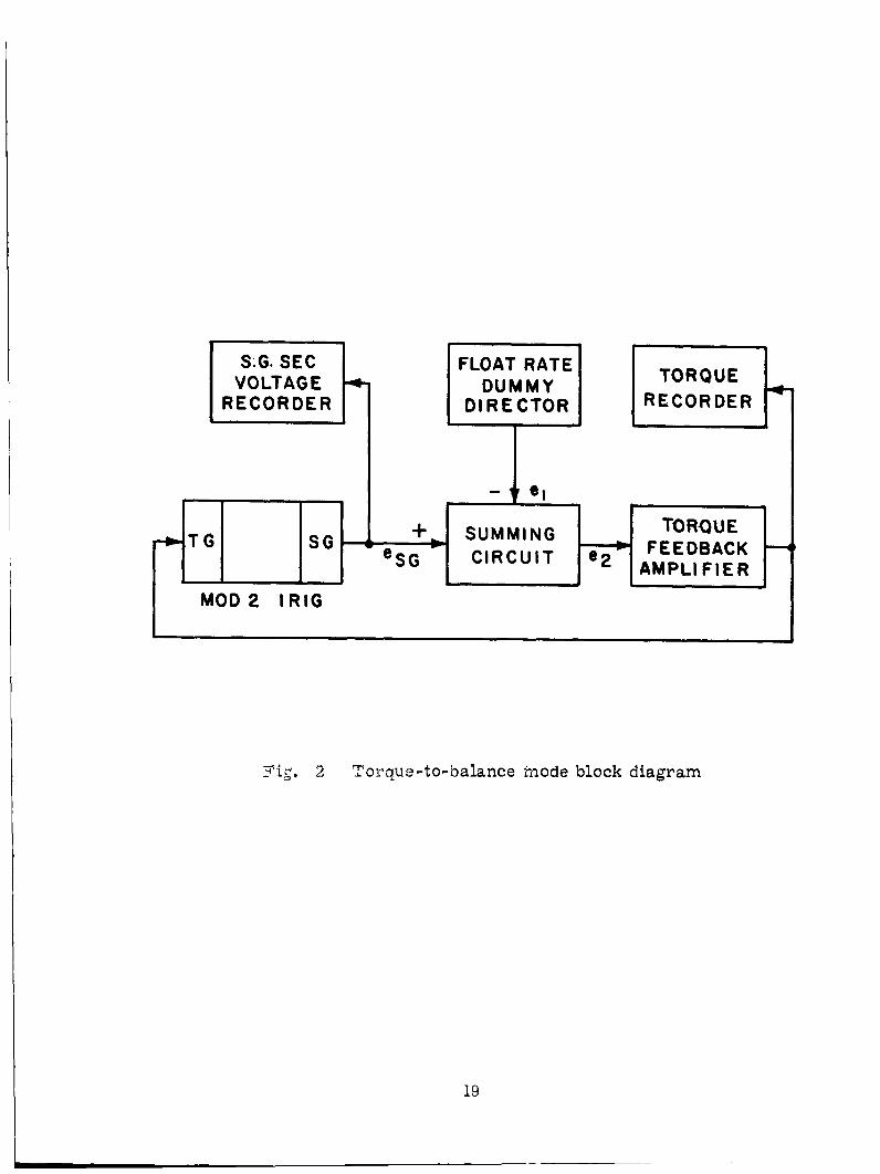
The gyro shall be at Operating Temperature, mounted on a servo table with table axis vertical, and operated in a torque-to- balance mode a s shown in the block diagram in Fig. 2.
4 . 2 . 3 .2 . 1 Test Equipment Requirements:
a. The Float Rate Dummy Director shall be capable of supplying a properly phased 3200 cps ramp voltage output e l equal to 10 mv/minute f 0. 570 over a continuous voltage range from - 50 mv (corresponding to positive float rotation about OA) to 0 mv and from 0 mv to + 50 mv (ne gat ive pos it ion about OA) .
18
S.G. SEC
RECORDER VOLTAGE
v
FLOAT RATE DUMMY
DIRECTOR 4- TORQUE
RECORDER
I
TORQUE - c . T
-
M O D 2 I R l G
+b FEEDBACK - SUMMING ,
CIRCUIT G S G . 2
e S G AMPLIFIER
- 1 2 rg. 2 Torque-to-balance inode block diagram
19

b. The torque recorder shall have a time constant
of 1 sec maximum and shall have no provision for damping adjustment.
4 . 2 . 3 .2 .2 Calibration and Gain Adjustment of the Torque Feedback Amplifier a. With the gyro positioned OA Vertical up, IA
east, wheel off and loop closed, adjust el to a phase of 180 f 0. 5' with eSG at +50 mv. Set el such that eSG is at -50 mv and measure the phase of el vs. eSG. This phase angle shall be 180 f 2O. This procedure constitutes proper phasing as mentioned in paragraph 4. 2. 3. 2. la.
b. With the gyro positioned as in step a above, measure the loop null voltage e2. Adjust el to + 25 mv. After settling occurs, instantaneously switch el to 0 mv and measure the time constant for e2 to drop from 20 mv to the null. Adjust the Torque Feedback Amplifier gain until this time is between 10 and 15 sec. All testing in para- graphs 4. 2 . 3. 2. 3 and 4. 2. 3. 2. 4 shall be done at this value of gain.
4. 2 . 3. 2 . 3
OA Vertical up, IA east, and shall be normally excited except wheel off. OA Vertical Freedom Test: The gyro shall be positioned
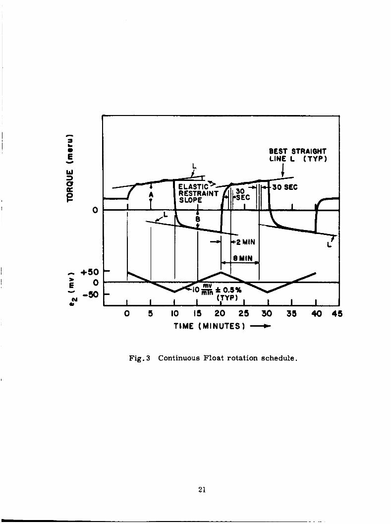
a. The Dummy Director signal el shall be varied according to the schedule in Fig. 3. The float torque shall be continuously recorded throughout the forty minutes of testing. This wil l result in a torque t race which is shown idealized in Fig. 3. The tape speed shall be approximately 0. 4 in. /min.
b. Best Straight Lines, L, shall be drawn through the steady-state portions of the torque trace.
20
- a
€ L 0
e
BEST STRAIGHT LINE L (TYP)
L
ELAI RES1 S LOF -
I
. I I I I 0 5 IO IS 20 25 30 35 40 45
TIME (MINUTES)
Fig, 3 Continuous Float rotation schedule,
21
C . Measure the slope of the Best Straight Line for the
first direction of float rotation. slope is shown in Fig. 3 and shall not exceed 3 meru/mv.
This Elastic Restraint
d . Record the average torque levels A and B (to the Best
Straight Line) at e l = 0 f 5 mv during the first cycle of Dummy Direction Voltage. Determine the Fluid Damping Torque, FDT, by calculating the average of the absolute values of A and B. (Refer to Fig. 3 . )
FDT = IAI + IBl 2
FDT shall be 1 3 0 f 2 5 meru.
e. Observe all spikes and deviations from the Best Straight Line. may differ by more than 60 meru from its particular Best Straight Line level. o r deviations greater than 1 5 meru from the Best Straight Line shall not exceed 90 meru.
No more than one spike o r deviation
The summation of all spikes
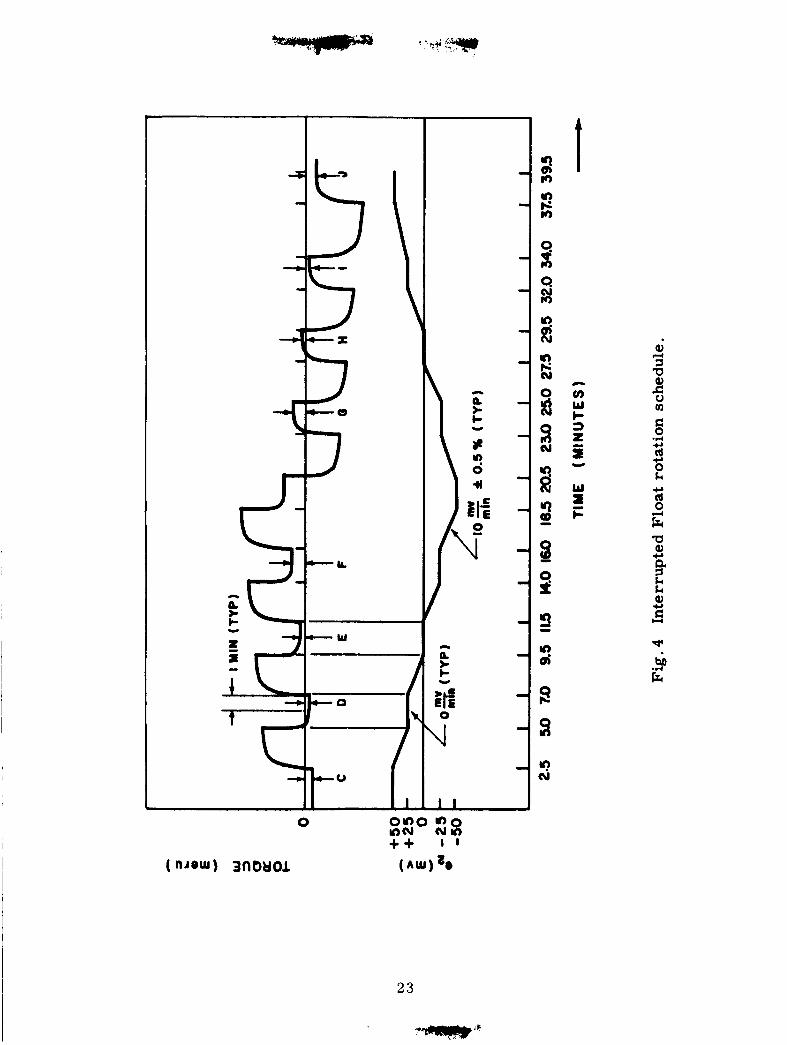
f . The Dummy Director signal shall be varied according to the schedule in Fig. 4 . This wil l result in a torque trace which is shown idealized in Fig. 4.
g. Intervals on the torque trace in which the Voltage rate is zero have been labelled C through J in Fig. 4. The average torque levels during the last minute of each of these 2 min intervals shall be algebraically subtracted as follows: C-J, D-I, E-H, and F-G. The absolute value of the difference between any of these te rms shall not exceed 2 0 meru.
4 . 2 . 3 . 2 . 4 IA Vertical Freedom Test
The gyro shall be positioned IA Vertical up, OA South, and shall be normally excited except wheel off.
Repeat a , b, and e of paragraph 4 . 2 . 3 . 2 . 3 adhering to the same requirements.
22
(AUJ)
t
c v) W t 3 z si Y
W s F
.PI * +J Ld 0 k
Ld 0
c,
E a Q) c,
4 k k Q)
E c,
U

NOTE: It is advisable to measure each of the four suspension voltages at some time during the first direction of float rotation in both the OA Vertical and IA Vertical gyro orientations. These voltage levels can be compared with the suspension voltages measured during prolonged deviations on the torque trace. This comparison can be used to distinguish problems due to fluid contamination from those involving pivot-and- jewel clearance, endshake, etc.
4.2.3.3
4. 2. 3. 3.1
Drift Te s t s
Reduced Excitation Drift with Input Axis UP: With the test turntable axis vertical so that the positive direction of the Gyro IA wil l be up and at l v microsyn excitation, the turntable is allowed to rotate for a time interval during which the turntable should rotate more than 12'.
Measure the total time for the turntable to rotate for the last 10 deg. Divide the total angle by the total time and convert to meru.
NOTE: Note the direction of Potation of the test turntable. When looking down from the top of the test turntable, clockwise rotation wil l give negative meru values, counterclockwise rotation wil l give positive meru values of drift with respect to the Earth.
Add algebraically, to the meru value obtained above, +lo00 times the sine of test station north latitude. The result of this addition is for the total uncompensated reduced excitation inertial space drift with 1 g of acceleration along the positive direction of the IA and is designated by the symbol Da.
0 The meru value at each increment of 1 angle is to be
graphically plotted against turntable angle.
4. 2. 3. 3. 2 Normal Excitation Drift with Input Axis Up: The
24

procedure above (paragraph 4. 2 . 3 . 3 . 1) is repeated with normal microsyn excitation of 2v. The value of the computation is the total uncompensated normal excitation inertial space drift with l g of acceleration along the positive direction of the IA and is
designated by the symbol Db.
4. 2. 3. 3 . 3
With the test turntable horizontal, the IRIG is aligned so that the positive direction of Gyro IA is north and the positive direction of the SRA is approximately vertically up. Excitation is the same as in paragraph 4. 2. 3. 3 . 2.
Normal Excitation Drift with Spin Reference Axis Up:
Measure the time interval for consecutive lo angle increments of the test turntable for a total of 10 increments.
NOTE: The test should be started with the SRA approximately 7O toward the east away from vertical so that at the end of 12 increments, the SRA w i l l be approximately 5O away from vertical to the west.
Measure the total time for the turntable to rotate for the loo increments symmetrically about the vertical. Divide the total angle by the total time and convert to meru.
Observing the note (paragraph 4. 2. 3. 3. 1) for the sign
of the meru value obtained above, add algebraically, +lo00 times the cosine of the test station north latitude. The result of this addition is the total uncompensated normal excitation inertial space drift with
l g of acceleration along the positive direction of the SRA and is designated by the symbol Dc.
4. 2 . 3. 3. 4 The procedure above (paragraph 4 . 2 . 3 . 3 . 3) is repeated with the IA north but with SRA approximately vertical down and with the test started approximately 7' toward the west away from the vertical. The excitation, computations, and plotting a r e the same as above (paragraph 4. 2. 3. 3 . 3). The result is the total uncompensated normal
Normal Excitation Dr i f t with Spin Reference Axis Down:
2 5
excitation inertial space drift with l g of acceleration along the
negative direction of the SRA and is designated by the symbol Dd.
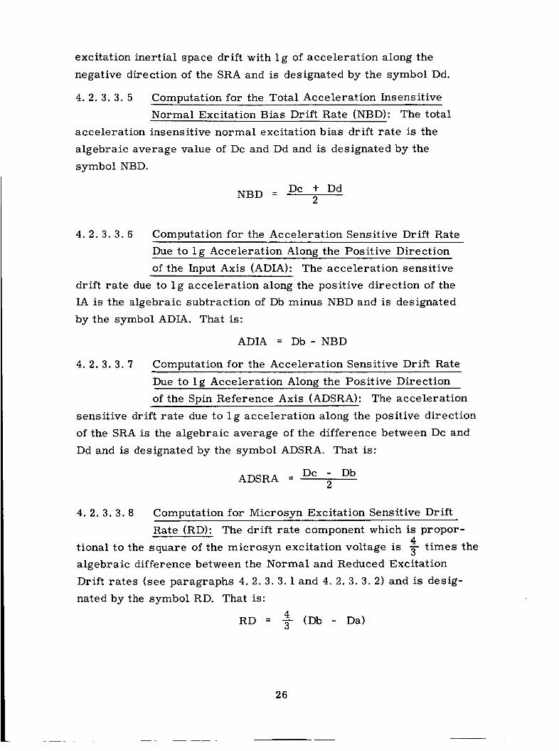
4. 2. 3. 3. 5 Computation for the Total Acceleration Insensitive Normal Excitation Bias Drift Rate (NBD): The total
acceleration insensitive normal excitation bias drift ra te is the algebraic average value of Dc and Dd and is designated by the symbol NBD.
Dc + Dd 2 NBD =
4. 2. 3 . 3. 6 Computation for the Acceleration Sensitive Drift Rate ~ ~~~~~~
Due to l g Acceleration Along: the Positive Direction of the Input Axis (ADIA): The acceleration sensitive
drift rate due to l g acceleration along the positive direction of the IA is the algebraic subtraction of Db minus NBD and is designated by the symbol ADIA. That is:
ADIA = Db-NBD
4. 2. 3. 3 . 7 Computation for the Acceleration Sensitive Drift Rate
Due to l g Acceleration Along the Positive Direction of the Spin Reference Axis (ADSRA): The acceleration
sensitive dr i f t ra te due to l g acceleration along the positive direction of the SRA is the algebraic average of the difference between Dc and Dd and is designated by the symbol ADSRA. That is:
DC - Db 2 ADSRA =
4. 2. 3. 3 . 8 Computation for Microsyn Excitation Sensitive Drift
Rate (RD): The drift rate component which is propor- 4 tional to the square of the microsyn excitation voltage is times the
algebraic difference between the Normal and Reduced Excitation Drift rates (see paragraphs 4. 2. 3. 3 . 1 and 4. 2. 3 . 3 . 2 ) and is desig- nated by the symbol RD. That is:
4 RD = (Db - Da)

4. 2 . 3 . 3 . 9 Computation fo r Independent Drift Rate (ID): The drift ra te component which is independent of microsyn excitation or case acceleration is computed by the formula below and is designated by the symbol Id. That is:
ID = NBD - RD
4 . 2 . 3 . 3. 10 Computation for the Standard Deviation of each Servo
Test: The standard deviation of the ten 1' drift rate values shall be calculated fo r each of the twelve servo tests. This computation shall be made by the following method:
al 0
I i = 1 0 1 (Xi -X)2 i =1
N
where Xi= drift rate at each of the ten lo points. - X = average drift rate of the ten 1' points. N = Number of points = 10
The standard deviation ol0 , shall not exceed 3 meru.
4. 2. 3. 4 Command Angle Torque Test
(1) This test shall be performed between the first and
second sets of the ser ies of the Performance tests specified
in paragraph 3.2. 1, section 11, i tems (5), (7) and (9).
(2) (a) The unit is orientated with its input axis parallel
to the table axis and vertically up.
(b) The servo loop is closed.
(c) A print is obtained from the forward backward
counter of the command pulses for every ten
table degrees.
(d) Torque is applied at the positive command angle
pulse rate (1600 pps).
27
(e) This test shall be run for 50' and the average of
the five prints determined.
agree with each other within 16 counts.
The five prints shall
(3)
command angle pulse ra te (1600 pps) and positive and negative
command angle pulse rate of 800 pps.
Item ( 2 ) paragraph 3. 2. 3. 4 is repeated for negative
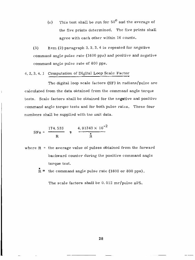
4. 2. 3. 4. 1 Computation of Digital Loop Scale Factor
The digital loop scale factors (SF) in radians/pulse a re
calculated from the data obtained from the command angle torque
tests.
command angle torque tests and for both pulse rates.
numbers shall be supplied with tile unit data.
Scale factors shall be obtained for the negative and positive
These four
174.533 4.91343 X loe2 SF* = 7 .I
R R
where R = the average value of pulses obtained from the forward
backward counter during the positive command angle
torque test.
R the command angle pulse ra te (1600 or 800 pps).
The scale factors shall be 0. 012 mr/pulse k570.
28
5. PREPARATION FOR DELIVERY
5.1 De live r y
A tag sheet, equivalent to Fig. 5, shall be packed with each IRIG listing the ser ia l number, vendor, and the following data particular to that unit:
Thermistor resistance s at flotation temperature. Values of suspension capacitors employed during acceptance tests . Temperature sensitivity. Total wheel time, average RDT (AT), standard de- viation of RDT (oT). Signal generator and torque generator equivalent IA sensitivities. Acceleration sensitive drift for l g of case ac- celer at ion with:
(a) Acceleration along the IA. (ADIA) (b) Acceleration along the SRA. (ADSRA)
Bias Drift (NBD) The Digital Angle Scale Factor and Command Angle Torque
Date of acceptance tests. The last 20 hours of dynamometer trace for the wheel in each unit shall be included.
Rate
NOTE: When values for (6). (7) and ( 8 ) are filled in on the Tag Sheet, the Tag Sheet shall be classified a s a CONFIDENTIAL Document.
6. NOTES
6. 1 Description (See Fig. 6)
The IRIG is a single degree of freedom gyro. Three
IRIGI s mounted on a stable platform maintain a reference for the
29

DATA SHEET
FOR GYRO MK 45 MOD 2 IRIG
t
Test Servo NBD ADSRA ADIA RD Date Station Run NO. -
c-1
Serial Number Manufacturer
Date of Acceptance Tests
ID
A. Performance Characteristics
1. Temperature Sensitivity meru/OF. 2. Maximum Float Friction meru.
3. Drift Parameters
a. Before Shrouding
meru. 4 . Maximum Standard Deviation (a 10)
B. Functional Characteristics
1. Thermistor Resistance at Floatation ohms. 2. S. G. Suspension Capacitor mfd. 3. T. G. Suspension Capacitor mfd.
4. S. G. Angle Voltage Sensitivity mvlmr . 5. Standard Deviation of RDT (a,) seconds . 6. Total Wheel Time hours,
Fig. 5
30

Fig. 6 2 5 Apollo IRIG(cutaway)
31
nonrotating, space-oriented axes in the Apollo Guidance and Navigation System. The IRIG contains: a gyro wheel, a floated gimbal in which the wheel is mounted, a microsyn torque generator, and a microsyn signal generator, both generators being mounted on
the floated gimbal axis. The spherical gimbal is immersed in a damping fluid of very carefully controlled viscosity, and the float axis is supported by a magnetic suspension at each end of the IRIG case.
6. 2
T a
- AF
AT -
ADIA
ADSRA
ID
RD
NBD
DNBD
DADIA
DADSRA
O10
Definitions of Symbols and Abbreviations. (All drift rates in meru with respect to inertial space. )
Standard deviation of Rundown Time (in seconds to 6000 rpm) from AT.
Average wheel rundown time (in seconds to 6000 r p d m e a s u r e d at final float run-in during manufacture.
Average wheel rundown time (in seconds to 6000 rpm)measured during acceptance test.
Acceleration sensitive drift rate due to 1 g of case acceleration along the positive IA Axis.
Acceleration sensitive drift rate due to 1 g of case acceleration along the positive SRA Axis.
Independent Drift Rate, independent of acceleration and microsyn excitation.
Microsyn excitation sensitive drift rate in meru.
Normal excitation total bias drift rate (acceleration ins ensit ive) .
The maximum difference of all NBD values.
The maximum difference of all ADIA values.
The maximum difference of all ADSRA .
Standard deviation of the ten 1' drift values in a
Servo test.
32