guidance, navigation, and control -...
TRANSCRIPT
GUIDANCE, NAVIGATION, AND CONTROL e QUICK REFERENCE DATA
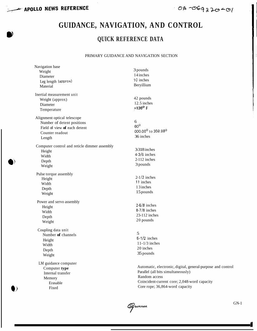
PRIMARY GUIDANCE AND NAVIGATION SECTION
Navigation base Weight Diameter Leg length (approx) Material
3 pounds 14 inches 10 inches Beryillium
Inertial measurement uni t Weight (approx) Diameter Temperature
Alignment optical telescope Number of detent positions Field of view of each detent Counter readout Length
Computer control and reticle dimmer assembly Height Width Depth Weight
Pulse torque assembly Height Width Depth Weight
Power and servo assembly Height Width Depth Weight
Coupling data uni t Number of channels Height Width Depth Weight
LM guidance computer Computer type Internal transfer Memory
Erasable Fixed
42 pounds 12.5 inches +126O F
6 60' OOO.OOo to 359.98' 36 inches
3-318 inches 4-318 inches 2-112 inches 3 pounds
2-1 12 inches 1 1 inches 1 3 inches 15 pounds
2.518 inches 8-718 inches 23-112 inches 20 pounds
5 5-112 inches 11-1/3 inches 20 inches 35 pounds
Automatic, electronic, digital, general-purpose and control Parallel (all bits simultaneously) Random access Coincident-current core; 2,048-word capacity Core rope; 36,864-word capacity
GN-1

APOLLO N E W S REFERENCE
LM guidance computer (cont)
Word length Number system Circuitry type Memory cycle time Add time Basic clock oscillator Power Supplies
Logic Parity
Data entry and display assembly Height Width Depth Weight Logic' levels
Clock frequency
Abort electronics assembly Computer type Height Width Depth Weight Power
Logic levels
Clock frequency Memory capacity
Fixed Erasable
Word Size
Abort sensor assembly Height Width Depth Weight Clock frequency Operating temperature
16 bits Binary 1's complement - for manipulation
12 microseconds 24 microseconds 2.048 MHz One +4-volt and one t14-volt switching regulator; operated from 28-volt d-c input power Positive (Positive dc = Binary 1 ; 0 volts = Binary 0) Odd
, Flat pack, NOR micrologic
ABORT GUIDANCE SECTION
7.3 inches 6.6 inches 5.6 inches 8.4 pounds Zero: 0 to 0.5 vdc One: +3 to +5 vdc 128 kpps
Automatic, electronic, digital, general-purpose 23.7 inches 9.0 inches 5.0 inches 32.5 pounds 12.5 watts (standby) 96.0 watts (operate) Zero: 0 to 0.5 vdc One: +3 to t 5 vdc 1,024 pps 4,096 words 2,048 words 2,048 words 18 bits
5.1 inches 9.0 inches 13.5 inches 20.7 pounds (with support) 128 kpps +120° F
GN-2
?. .,
*,&, APOLLO NEWS REFERENCE
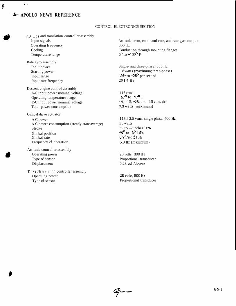
CONTROL ELECTRONICS SECTION
c) Attitude and translation controller assembly Input signals Attitude error, command rate, and rate gyro output Operating frequency 800 H z Cooling Conduction through mounting flanges Temperature range 0' to +160° F
Rate gyro assembly Input power Starting power Input range Input rate frequency
Descent engine control assembly A-C input power nominal voltage Operating temperature range D-C input power nominal voltage Total power consumption
Single- and three-phase, 800 H Z
1.8 watts (maximum; three-phase) -25O to +25O per second 20 f 4 H z
115 vrms +57O to +97O F +4, +I 5, +28, and -1 5 volts dc 7.9 watts (maximum)
Gimbal drive actuator A-C power 115 f 2.5 vrms, single phase, 400 Hz A-C power consumption (steady-state average) 35 watts Stroke +2 to -2 inches 55% Gimbal position +6O to -6' 55% Gimbal rate 0.2OIsec ? I 0% Frequency of operation 5.0 Hz (maximum)
a Attitude controller assembly Operating power 28 volts. 800 H z Type of sensor Proportional transducer Displacement 0.28 volt/degree
Thrust/translation controller assembly Operating power Type of sensor
28 volts, 800 Hz Proportional transducer
GN -3 I
APOLLO NEWS REFERENCE
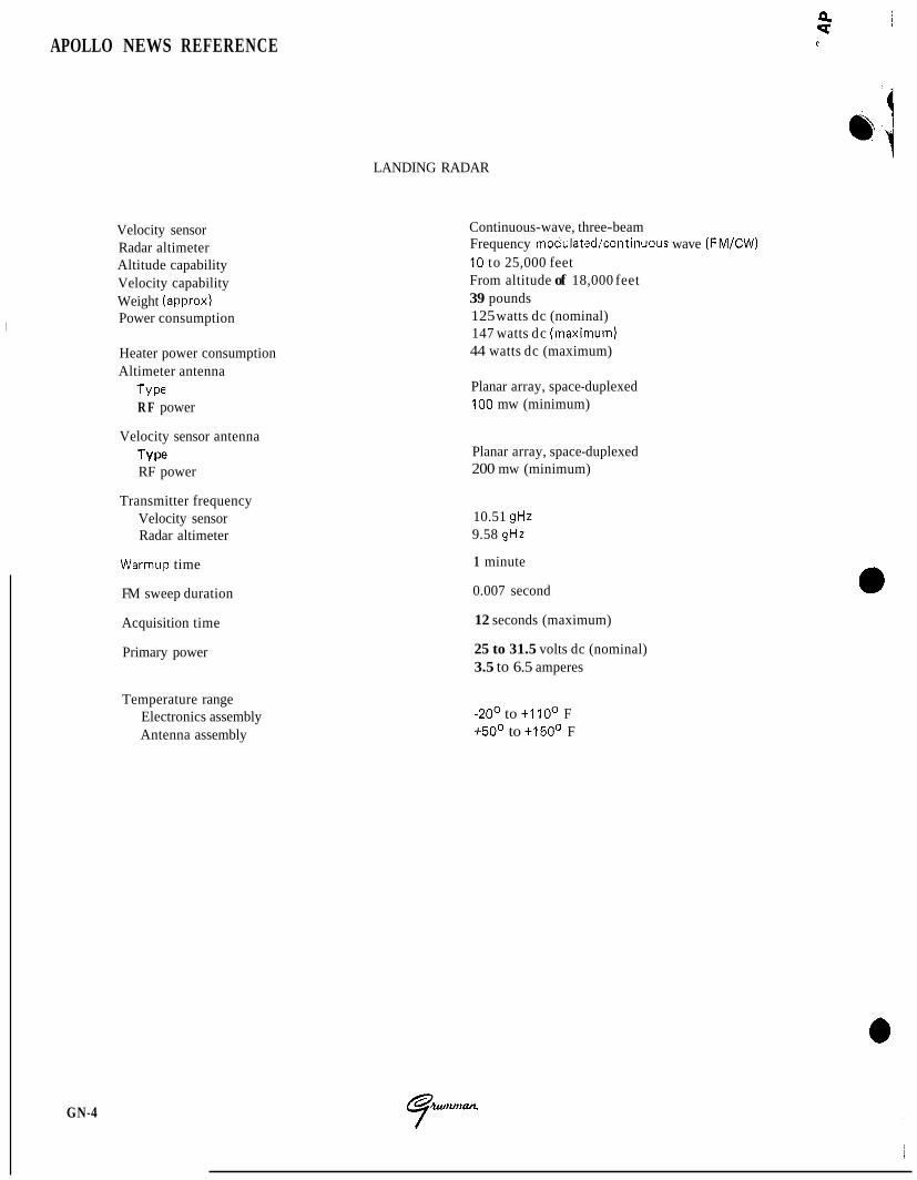
Velocity sensor Radar altimeter Altitude capability Velocity capability Weight (approx) Power consumption
Heater power consumption Altimeter antenna
TY Pe R F power
GN-4
Velocity sensor antenna Type RF power
Transmitter frequency Velocity sensor Radar altimeter
Warmup time
FM sweep duration
Acquisition time
Primary power
Temperature range Electronics assembly Antenna assembly
LANDING RADAR
Continuous-wave, three-beam Frequency modulated/continuous wave (FM/CW) 10 to 25,000 feet From altitude of 18,000 feet 39 pounds 125 watts dc (nominal) 147 watts dc (maximurn) 44 watts dc (maximum)
Planar array, space-duplexed 100 mw (minimum)
Planar array, space-duplexed 200 mw (minimum)
10.51 gHz 9.58 gHz
1 minute
0.007 second
12 seconds (maximum)
25 to 31.5 volts dc (nominal) 3.5 to 6.5 amperes
-20' to +I IOo F +50° to +150° F
0 N E W S REFERENCE
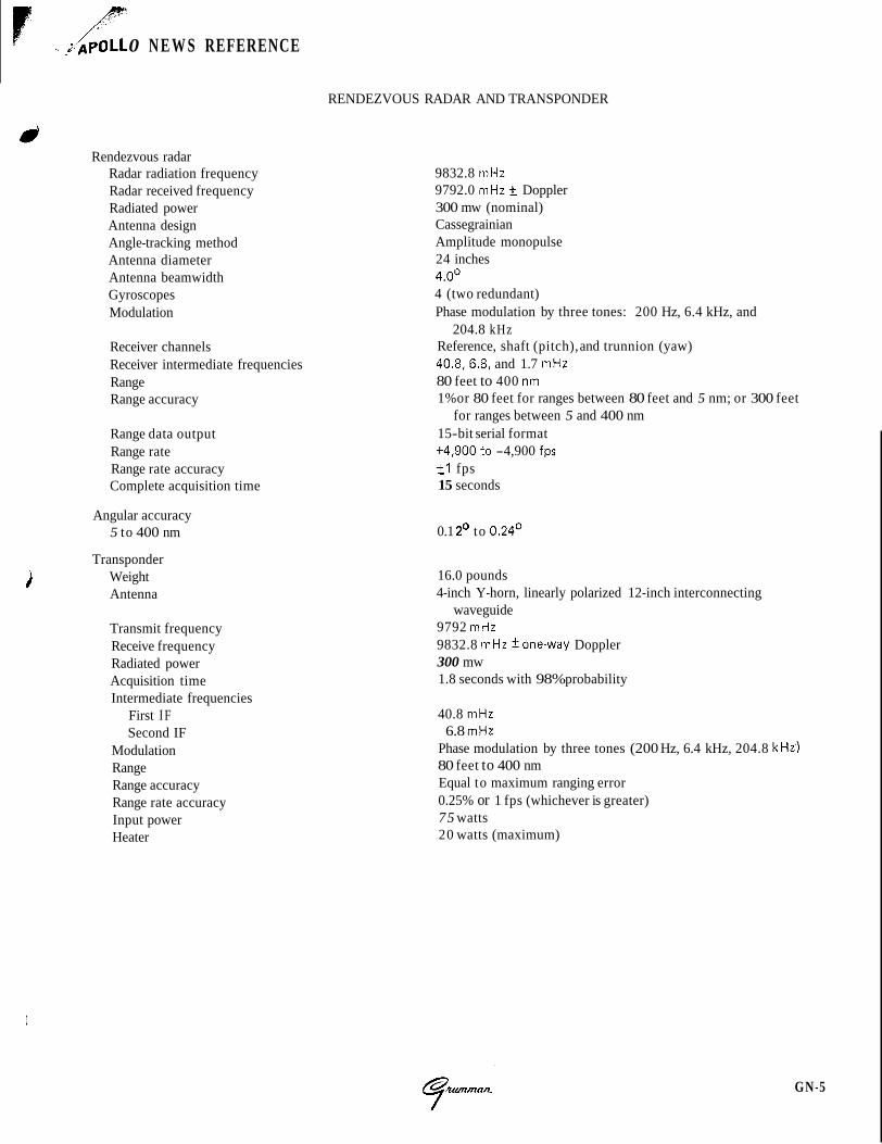
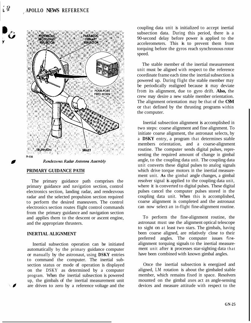
RENDEZVOUS RADAR AND TRANSPONDER
Rendezvous radar Radar radiation frequency Radar received frequency Radiated power Antenna design Angle-tracking method Antenna diameter Antenna beamwidth Gyroscopes Modulation
Receiver channels Receiver intermediate frequencies Range Range accuracy
Range data output Range rate Range rate accuracy Complete acquisition time
Angular accuracy 5 to 400 nm
Transponder Weight Antenna
Transmit frequency Receive frequency Radiated power Acquisition time Intermediate frequencies
First IF Second IF
Modulation Range Range accuracy Range rate accuracy Input power Heater
9832.8 mHz 9792.0 mHz +_ Doppler 300 mw (nominal) Cassegrainian Amplitude monopulse 24 inches 4.0' 4 (two redundant) Phase modulation by three tones: 200 Hz, 6.4 kHz, and
204.8 kHz Reference, shaft (pitch), and trunnion (yaw) 40.8,6.8, and 1.7 mHz 80 feet to 400 nm 1% or 80 feet for ranges between 80 feet and 5 nm; or 300 feet
15-bit serial format for ranges between 5 and 400 nm
+4,900 to -4,900 fps f l fps 15 seconds
0.1 2' to 0.24'
16.0 pounds 4-inch Y-horn, linearly polarized 12-inch interconnecting
waveguide 9792 mHz 9832.8 mHz *one-way Doppler 300 mw 1.8 seconds with 98% probability
40.8 mHz 6.8 mHz
Phase modulation by three tones (200 Hz, 6.4 kHz, 204.8 kHz) 80 feet to 400 nm Equal to maximum ranging error 0.25% or 1 fps (whichever is greater) 75 watts 20 watts (maximum)
i
GN-5
APOLLO NEWS REFERENCE
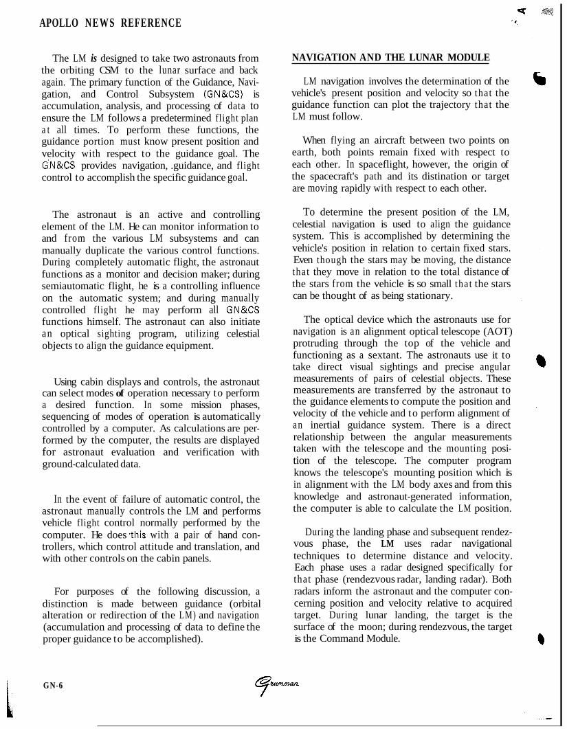
The LM is designed to take two astronauts from the orbiting CSM to the lunar surface and back again. The primary function of the Guidance, Navi- gation, and Control Subsystem (GN&CS) is accumulation, analysis, and processing of data to ensure the LM follows a predetermined fl ight plan a t all times. To perform these functions, the guidance portion must know present position and velocity with respect to the guidance goal. The G'N&CS provides navigation, .guidance, and flight control to accomplish the specific guidance goal.
The astronaut is an active and controlling element of the LM. He can monitor information to and from the various LM subsystems and can manually duplicate the various control functions. During completely automatic flight, the astronaut functions as a monitor and decision maker; during semiautomatic flight, he is a controlling influence on the automatic system; and during manually controlled fl ight he may perform all GN&CS functions himself. The astronaut can also initiate an optical sighting program, utilizing celestial objects to align the guidance equipment.
Using cabin displays and controls, the astronaut can select modes of operation necessary to perform a desired function. In some mission phases, sequencing of modes of operation is automatically controlled by a computer. As calculations are per- formed by the computer, the results are displayed for astronaut evaluation and verification with ground-calculated data.
In the event of failure of automatic control, the astronaut manually controls the LM and performs vehicle flight control normally performed by the computer. He does ,this with a pair of hand con- trollers, which control attitude and translation, and with other controls on the cabin panels.
For purposes of the following discussion, a distinction is made between guidance (orbital alteration or redirection of the LM) and navigation (accumulation and processing of data to define the proper guidance to be accomplished).
GN-6
NAVIGATION AND THE LUNAR MODULE
LM navigation involves the determination of the vehicle's present position and velocity so that the guidance function can plot the trajectory that the LM must follow.
When flying an aircraft between two points on earth, both points remain fixed with respect to each other. In spaceflight, however, the origin of the spacecraft's path and its distination or target are moving rapidly with respect to each other.
To determine the present position of the LM, celestial navigation is used to align the guidance system. This is accomplished by determining the vehicle's position in relation to certain fixed stars. Even though the stars may be moving, the distance that they move in relation to the total distance of the stars from the vehicle is so small tha t the stars can be thought of as being stationary.
The optical device which the astronauts use for navigation is an alignment optical telescope (AOT) protruding through the top of the vehicle and functioning as a sextant. The astronauts use it to take direct visual sightings and precise angular measurements of pairs of celestial objects. These measurements are transferred by the astronaut to the guidance elements to compute the position and velocity of the vehicle and to perform alignment of an inertial guidance system. There is a direct relationship between the angular measurements taken with the telescope and the mounting posi- tion of the telescope. The computer program knows the telescope's mounting position which is in alignment with the LM body axes and from this knowledge and astronaut-generated information, the computer is able to calculate the LM position.
During the landing phase and subsequent rendez- vous phase, the LM uses radar navigational techniques to determine distance and velocity. Each phase uses a radar designed specifically for that phase (rendezvous radar, landing radar). Both radars inform the astronaut and the computer con- cerning position and velocity relative to acquired target. During lunar landing, the target is the surface of the moon; during rendezvous, the target is the Command Module.
R-44
GN-7
APOLLO NEWS REFERENCE
GUIDANCE AND THE LUNAR MODULE
After the position and velocity of the LM are determined, the guidance function establishes the steering for the predetermined fl ight path. Since objects in space are moving targets (as compared to those on earth, which are stationary), the guidance problem involves aiming not a t the target‘s present position but a t the position in which it will be when the vehicle path intersects the target path. On earth, the guidance problem is a two- dimensional one; it involves only longitude and latitude. In space, a third dimension is introduced; position cannot be plotted in earth terms.
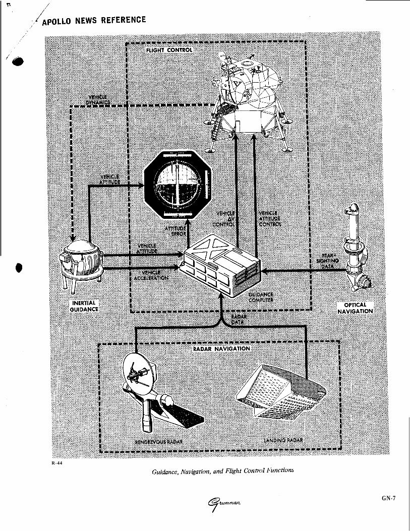
To calculate the guidance parameters, a reference coordinate frame must be determined. A three- axis, right-hand, orthogonal, coordinate frame (inertial reference frame) is used. It is fixed in space and has an unchanging angular relationship with the stars. Its dimensional axes are designated as X, Y , and 2, and all spacecraft positions and velocities are related to this frame. The astronaut establishes this frame by sighting of celestial objects using the AOT. The vertical axis is desig- nated as the X-axis. Its positive direction is from the descent stage to the ascent stage, passing through the overhead hatch. The lateral axis is designated as the Y-axis. Its positive direction is from left to right across the astronauts shoulders when they are facing the windows in the LM cabin. To complete the three three-axis orthogonal system, the Z-axis is perpendicular to the X and Y axes. This axis is referred to as the forward axis, because +Z-axis direction is through the forward hatch. The +Z-axis is also used as the zero refer- ence line for all angular measurements.
The guidance system based on this coordinate frame is referred to as an inertial guidance system. Inertial guidance provides information about the actual path of the vehicle in relation to a predeter- mined path. All deviations are transmitted to a flight control system. The inertial guidance system performs these functions without information from outside the vehicle. The system stores the predetermined flight plan, then automatically but not continuously, computes distance and velocity for a given mission time (called the state vector) of the vehicle to compensate, through vehicle control, for changes in direction.
+ X-AXIS
.t.
R - 4 5
- X-AXIS
LM Vehicle Axes
Inertial guidance systems are based on measure- ments made by accelerometers mounted on a structure called the stable member or platform. The stable member, in turn, is mounted inside three spherical gimbals, one for each principal axis of motion. Gyroscopes mounted on the stable member drive the gimbals to isolate the stable member from changes in LM attitude and hold the stable member in a fixed inertial position.
During flight, the stable member’s axes must be held in fixed relation to the inertial reference frame regardless of the LM motion; otherwise resolvers mounted on each gimbal issue error signals. These error signals are used by the com- puter to generate commands to correct the attitude of the LM. The rotational axes of the LM are desig- nated as yaw, pitch, and roll. Yaw rotation, about the X-axis affects the vehicle in the Y-Z plane. The effect is analogous to spinning around one‘s heels. Pitch rotation, about the Y-axis, affects the vehicle in the X-Z plane. The effect is analogous to a gymnast performing a somersault. Roll rotation, about the Z-axis, affects the vehicle in the X-Y plane. The effect is analogous to a person doing a
G N - 8

:./APOLLO NEWS REFERENCE
cartwheel. Positive rotation is determined by the right-hand rule, This involves placing the thumb of the right hand in the positive direction of the axis about which rotation is to be determined. Then the remainder of the fingers are curled around the axis. The direction in which the fingers point is con- sidered the direction of positive rotation.
FLIGHT CONTROL AND THE LUNAR MODULE
Flight control involves controlling the LM trajectory (flight path) and attitude. Flight path control depends on the motion of the LM center of gravity; attitude control primarily involves rota- tions about the center of gravity.
In controlling the LM in its flight path, the thrust of its engines must be directed so t h a t it produces a desired variation in either magnitude or direction to place the LM in some particular orbit, position, or attitude. The major velocity changes associated with the lunar orbit, injection, landing, and ascent phases of the mission are accomplished by either the descent propulsion section or ascent
propulsion section of the Main Propulsion Sub- system (MPS). The engines can produce high thrust in specific directions in inertial space.
During the descent phase, the LM must be slowed (braked) to place i t in a transfer orbit from which it can make a soft landing on the lunar surface. To accomplish braking, descent engine thrust is controllable so that the precise velocity (feet per second) necessary to alter the vehicle’s trajectory can be achieved. For a soft landing on the lunar surface, the weight of the LM must be matched by an upward force so that a state of equilibrium exists, and from this point, the descent engine is shut off and the LM free falls to the lunar surface. The thrust of the descent engine provides this upward force, and since the weight of the vehicle is a variable (due to consumption of expendables) this is another reason why the magnitude of the engine thrust is controllable. In addition, the center of gravity is also variable and the thrust must be such that it is in line with the LM center of gravity. This is accomplished by gimbaling (tilting) the descent engine.
R-46
LM Powered Descent Profile
GN-9
APOLLO NEWS REFERENCE
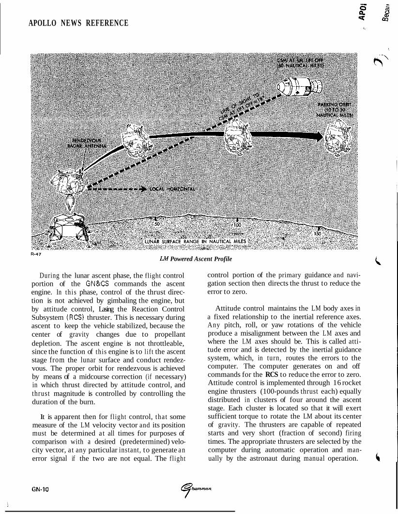
LM Powered Ascent Profile
During the lunar ascent phase, the flight control portion of the GN&CS commands the ascent engine. In this phase, control of the thrust direc- tion is not achieved by gimbaling the engine, but by attitude control, Lasing the Reaction Control Subsystem (RCS) thruster. This is necessary during ascent to keep the vehicle stabilized, because the center of gravity changes due to propellant depletion. The ascent engine is not throttleable, since the function of this engine is to l if t the ascent stage from the lunar surface and conduct rendez- vous. The proper orbit for rendezvous is achieved by means of a midcourse correction (if necessary) in which thrust directed by attitude control, and thrust magnitude is controlled by controlling the duration of the burn.
It is apparent then for fl ight control, that some measure of the LM velocity vector and its position must be determined at all times for purposes of comparison with a desired (predetermined) velo- city vector, at any particular instant, to generate an error signal if the two are not equal. The fl ight
control portion of the primary guidance and navi- gation section then directs the thrust to reduce the error to zero.
Attitude control maintains the LM body axes in a fixed relationship to the inertial reference axes. Any pitch, roll, or yaw rotations of the vehicle produce a misalignment between the LM axes and where the LM axes should be. This is called atti- tude error and is detected by the inertial guidance system, which, in turn, routes the errors to the computer. The computer generates on and off commands for the RCS to reduce the error to zero. Attitude control is implemented through 16 rocket engine thrusters (100-pounds thrust each) equally distributed in clusters of four around the ascent stage. Each cluster is located so that it will exert sufficient torque to rotate the LM about its center of gravity. The thrusters are capable of repeated starts and very short (fraction of second) firing times. The appropriate thrusters are selected by the computer during automatic operation and man- ually by the astronaut during manual operation.
G N - 1 0
, :/bPOLLO NEWS REFERENCE
Because the astronauts frequently become part of the control loop in this highly flexible system, a
their use. These displays include attitude and velocity, radar data, fuel and oxidizer parameters, caution and warning information, total velocity change information, timing and other information to assist them in completing their mission.
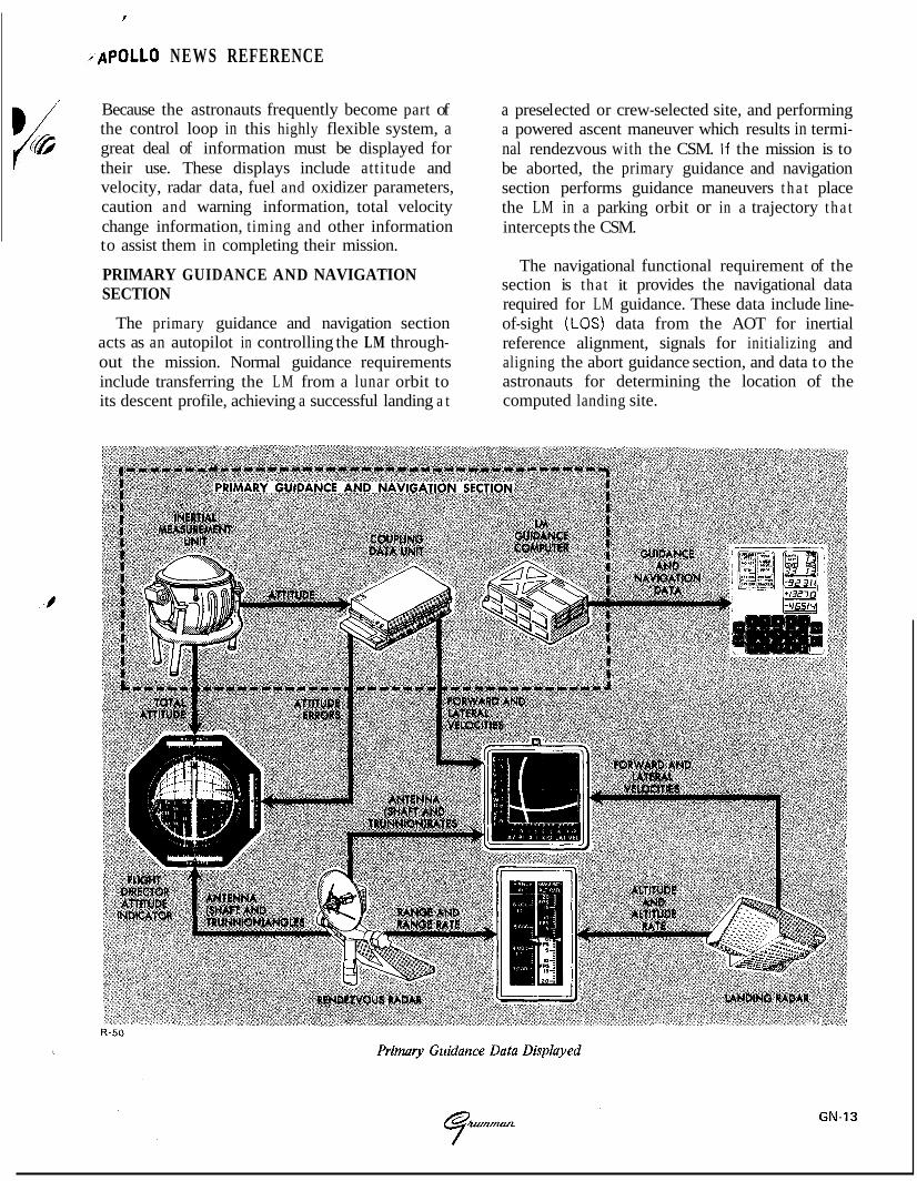
PRIMARY GUIDANCE AND NAVIGATION SECTION
great deal of information must be displayed for
The primary guidance and navigation section acts as an autopilot in controlling the LM through- out the mission. Normal guidance requirements include transferring the LM from a lunar orbit to its descent profile, achieving a successful landing a t
a pres el ected or crew-selected site, and performing a powered ascent maneuver which results in termi- nal rendezvous with the CSM. If the mission is to be aborted, the primary guidance and navigation section performs guidance maneuvers t h a t place the LM in a parking orbit or in a trajectory t h a t intercepts the CSM.
The navigational functional requirement of the section is that it provides the navigational data required for LM guidance. These data include line- of-sight (LOS) data from the AOT for inertial reference alignment, signals for initializing and aligning the abort guidance section, and data to the astronauts for determining the location of the computed landing site.
APOLLO N E W S REFERENCE
The primary guidance and navigation section includes three major subsections: inertial, optical, and computer. Individually or in combination they perform all the functions mentioned pre- viously.
The inertial subsection establishes the inertial reference frame that is used as the central coor- dinate system from which all measurements and computations are made. The inertial subsection measures attitude and incremental velocity changes, and assists in converting data for com- puter use, onboard display, or telemetry. Opera- tion is started automatically by the guidance computer or by an astronaut using the computer keyboard. Once the subsection is energized and aligned to the inertial reference, any LM rotation (attitude change) is sensed by the stable member. All inertial measurements (velocity and attitude) are with respect to the stable member. These data are used by the computer in determining solu- tions to the guidance problems.
The optical subsection is used to determine the position of the LM, using a catalog of stars stored in the computer and celestial measurements made by an astronaut. The identity of celestial objects is determined before earth launch. The AOT is used by the astronaut to take direct visual sightings and precise angular measurements of a pair of celestial objects. The computer subsection uses this data along with prestored data to compute position and velocity and to align the inertial components.
The computer subsection, as the control and data processing center of the LM, performs all the guidance and navigation functions necessary for automatic control of the path and attitude of the vehicle. For these functions, the GN&CS uses a digital computer. The computer is a control computer with many of the features of a general- purpose computer. As a control computer, it aligns the stable member and positions both radar antennas. It also provides control commands to both radars, the ascent engine, the descent engine, the RCS thrusters, and the LM cabin dis- plays. As a general-purpose computer, it solves guidance problems required for the mission.
GN-14
I
ABORT GUIDANCE SECTION
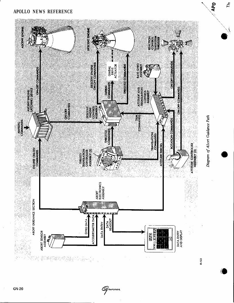
The abort guidance section is used as backup for the primary guidance and navigation section during a LM mission abort. I t determines the L M trajectory or trajectories required for rendezvous with the CSM and can guide the LM from any point in the mission, from LM-CSM separation to LM-CSM rendezvous and docking, including ascending from the lunar surface. It can provide data for altitude displays, and making explicit guidance computations and also issue commands for firing and shutting down engines. Guidance can be accomplished automatically or manually by the astronauts, based on data from the abort guidance section.
The abort guidance section is an inertial system rigidly strapped to the LM rather than mounted on a stabilized platform. Use of the strapped-down inertial system, rather than a gimbaled system, offers sufficient accuracy for LM missions, a t savings in size and weight. Another feature is tha t it can be updated with radar and optical aids.
CONTROL ELECTRONICS SECTION
The control electronics section processes RCS and MPS control signals for vehicle stabilization and control. To stabilize the LM during all phases of the mission the control electronics section pro- vides signals tha t fire any combination of the 16 RCS thrusters. These signals control attitude and translation about or along all axes. The attitude and translation control data inputs originate from the primary guidance and navigation section during normal automatic operation from two hand controllers during manual operations, or from the abort guidance section during certain abort situations.
The control electronics section also processes on and off commands for the ascent and descent engines, and routes automatic and manual throttle commands to the descent engine. Trim control of the gimbaled descent engine is also provided to assure that the th rus t vector operates through the LM center of gravity.
\ a‘
e

r ; P P OLLO NEWS REFERENCE
1 ” LANDING RADAR
The landing radar, located in the descent stage, provides altitude and velocity data during lunar descent. The primary guidance and navigation section calculates control signals for descent rate, hovering, and soft landing. Altitude data begins at approximately 25,000 feet above the lunar surface; velocity data, a t approximately 18,000 feet.
The landing radar uses four microwave beams; three to measure velocity by Doppler shift contin- uous wave, one to measure altitude by continuous-wave frequency modulation.
RENDEZVOUSRADAR
The rendezvous radar, operated in conjunction with a CSM transponder, acquires and tracks the CSM before and during rendezvous and docking. The radar, located in the ascent stage, tracks the CSM during the descent phase of the mission to supply tracking data for any required abort man- euver and during the ascent phase to supply data for rendezvous and docking. When the radar tracks the CSM, continuous measurements of range, range rate, angle, and angle rate (with respect to the LM) are provided simultaneously to the primary guidance and navigation section
i. R-51
Nominal Descent Trajectoly from High Gate to Touchdown
Ymntm G N - 1 5
APOLLO NEWS REFERENCE
and to LM cabin displays. This allows rendezvous to be performed automatically under computer control, or manually by the astronauts. During the rendezvous phase, rendezvous radar per- formance is evaluated by comparing radar range and range rate tracking values with MSFN track- ing values.
The CSM transponder receives an X-band t h ree-tone phase-modulated, continuous-wave signal from the rendezvous radar, offsets the signal by a specified amount, and then transmits a phase-coherent carrier frequency for acquisition by the radar. This return signal makes the CSM appear as the only object in the radar field of view. The transponder provides the long range (400 nm) required for the mission.
The transponder and the radar use solid-state varactor frequency-multiplier chains as trans- mitters, to provide high reliability. The radar antenna is space stabilized to negate the effect of LM motion on the line-of-sight angle. The gyros used for this purpose are rate-integrating types; in the manual mode they also supply accurate line- of-sight, angle-rate data for the astronauts. Range rate is determined by measuring the two-way Doppler frequency shift on the signal received from the transponder. Range is determined by measuring the time delay between the received and the transmitted three-tone phase-modulated waveform.
FUNCTIONAL DESCRIPTION
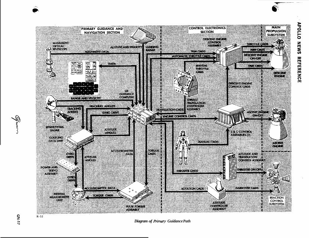
The GN&CS comprises two functional loops, each of which is an independant guidance and control path. The primary guidance path contains elements necessary to perform all the functions required to complete the LM mission. If a failure occurs in this path the abort guidance path can be substituted. To understand these two loops, the function of each major component of GN&CS equipment must be known.
GN-16
PRIMARY GUIDANCE AND NAVIGATION SECTION
INERTIAL SUBSECTION
The inertial subsection consists of a navigation base, an inertial measurement unit, a coupling data unit, pulse torque assembly, power and servo assem- bly, and signal conditioner assembly.
The navigation base is a lightweight mount that supports in accurate alignment, the inertial meas- urement un i t ( I M U ) , the AOT, and an abort sensor assembly (part of the abort guidance section). Structurally, it consists of a center ring with four legs that extend from either side of the ring. The inertial measurement unit is mounted to the legs on one end and the telescope and the abort sensor assembly are mounted on the opposite side.
The inertial measurement is the primary inertial sensing device of the LM. I t is a three-degree-of- freedom, stabilized device t h a t maintains an orthogonal, inertially referenced coordinate system for LM attitude control and maintains three accelerometers in the reference coordinate system for accurate measurement of velocity changes.
The coupling data unit converts and transfers angular information between the navigation and guidance hardware. The unit is an electronic device t h a t performs analog-to-digital and digital- to-analog conversions. The coupling data un i t processes the three attitude angles associated with the inertial reference and the two angles asso- ciated with the rendezvous radar antenna.
The pulse torque assembly supplies inputs to, and processes outputs from, the inertial compo- nents in the inertial subsection.
* t 3
GI z
7”-
R - 5 2
Diagram of primary Guidance Path

APOLLO N E W S REFERENCE
The power and servo assembly contains elec- tronic equipment in support of the primary guid- ance and navigation section: power supplies for generation of internal power required by the section, servomechanisms for the inertial measure- ment unit, and temperature control circuitry for the inertial measurement unit.
The signal conditioner assembly provides an interface between the primary guidance and navi- gation section, and the Instrumentation Sub- . system (IS).
OPTICAL SUBSECTION
The optical subsection consists of the align- ment optical telescope and a computer control and reticle dimmer assembly.
The alignment optical telescope, an L-shaped periscope approximately 36 inches long, is used by the astronaut to take angular measurements of celestial objects. These angular measurements are required for orienting the stable member during certain periods while the LM is in flight and dur- ing prelaunch preparations while on the lunar surface. Sightings taken with the telescope are transferred to the computer by the astronaut using the computer control and reticle dimmer assembly. This assembly also controls the bright- ness of the telescope reticle pattern.
COMPUTER SUBSECTION
The computer subsection consists of the LM guidance computer (LGC) and a display and key- board, which is a computer control panel. The display and keyboard is commonly referred to as "the DSKY" (pronounced "disky").
The guidance computer processes data and issues discrete control signals for various subsystems. It is a control computer with many of the features of a general-purpose computer. As a control computer, it aligns the inertial measurement unit stable mem- ber and provides rendezvous radar antenna drive commands. The LGC also provides control com- mands to the landing and rendezvous radars, the ascent and descent engines, the RCS thrusters, and the cabin displays. As a general purpose computer,
it solves guidance problems required for the \\-\ mission. In addition, the guidance computer moni- tors the operation of the primary guidance and 0' navigation section.
The guidance computer stores data pertinent to the ascent and descent flight profiles that the LM must assume to complete its mission. These data (position, velocity, and trajectory information) are used by the computer to solve flight equa- tions. The results of various equations are used to determine the required magnitude and direction of thrust. The computer establishes corrections to be made. The LM engines are turned on a t the correct time, and steering commands are con- trolled by the computer to orient the LM to a new trajectory, if required. The inertial sub- section senses acceleration and supplies velocity changes to the computer for calculating total velocity. Drive signals are supplied from the com- puter to the coupling data unit and stabilization gyros in the inertial subsection to align the gimbal angles in the inertial measurement unit. Stable-member position signals are supplied to the computer to indicate attitude changes.
The computer provides drive signals to the to rendezvous radar for antenna positioning and receives, from the rendezvous radar channels of the coupling unit, antenna angle information. The computer uses this information in the antenna- positioning calculations. During lunar-landing operations, star-sighting information is manually loaded into the computer, using the DSKY. This information is used to calculate alignment com- mands for the inertial measurement unit . The LM guidance computer and its programming help meet the functional requirements of the mission. The functions performed in the various mission phases include both automatic and semiautomatic opera- tions that are implemented mostly through the execution of the programs stored in the computer memory.
The DSKY provides a two-way communi- cations link between the astronauts and the LM guidance computer. The astronauts are able to insert various parameters into the computer, display data from the computer, and to monitor data in the computer's memory. I @
GN-18

r b I (D APOLLO NEWS REFERENCE
/
ABORT GUIDANCE SECTION
The abort guidance section consists of an abort sensor assembly, a data entry and display assembly (DEDA), and an abort electronics assembly, The data entry and display assembly is commonly referred to as "the DEDA" (pronounced "deeda").
The abort sensor assembly, by means of gyros and accelerometers, provides incremental attitude information around the LM X, Y , and Z axes and incremental velocity changes along the LM X, Y , and Z axes. Data pulses are routed to the abort electronic assembly, which uses the LM attitude and velocity data for computation of steering errors.
The DEDA is used by the astronauts to select the desired mode of operation, insert the desired targeting parameters, and monitor related data throughout the mission. To select a mode of opera- tion or insert data, three digits (word address) then a plus (+) or minus (-), and finally, a five digit code must be entered. If this sequence is not followed, an operator error light goes on when the enter pushbutton is pressed. To read out any parameter,
'0 three digits (address of the desired word) must be entered and a readout pushbutton pressed.
The abort electronics assembly, by means of special input-output subassemblies, interfaces the abort guidance secton with the other LM sub- systems and displays. This assembly is basically a general-purpose digital computer, which solves guidance and navigation problems. Mode and submode entries coupled from the data entry and display assembly determine the operation of the computer. The computer uses incremental velocity and attitude inputs from the abort sensor assembly to calculate LM position, attitude, and velocity in the inertial reference frame. It routes altitude and altitude-rate data to altitude and altitude rate indicators; out of plane velocity data, to X-pointer indicators. Also, roll, pitch and yaw steering error signals are routed to flight director altitude indicators.
Engine-on commands are routed to the appro- priate engine via the control electronics section when the following occur: an abort or abort stage pushbutton is pressed, appropriate switches are set, necessary data are entered into the DEDA, and velocity-to-be-gained exceeds a predetermined threshold (currently 2.1 fps). At the appropriate time, as determined by velocity-to-be-gained, an engine-off command is sent.
CONTROL ELECTRONICS SECTION
The control electronics section comprises two a t t i tude controller assemblies, two thrust/ translation controller assemblies, an attitude and translation control assembly, a rate gyro assembly, descent engine control assembly, and three stabil- ization and control (S&C) control assemblies.
The attitude controller assemblies are right-hand pistol grip controllers, which the astronauts use to command changes in LM attitude. These control- lers function in a manner similar to an aircraft's "control stick". Each is installed with its longitu- dinal axis approximately parallel to LM X-axis; vehicle rotations correspond to astronaut hand movements.
The thrust/translation controller assemblies are left-hand controllers used by the astronauts to con- trol LM translation in any axis. Vehicle translations correspond approximately to the astronauts hand movements.
The attitude and translation control assembly routes the RCS thruster on and off commands from the guidance computer to the thrusters, in the primary control mode. During abort guidance control, the assembly acts as a computer in deter- mining which RCS thrusters are to be fired.
The rate gyro assembly is used during abort guidance control to supply the attitude and trans- lation control assembly with damping signals to limit vehicle rotation rates and to facilitate manual rate control.
GN-19
APOLLO N E W S REFERENCE
APOLLO NEWS REFERENCE
0
The descent engine control assembly processes engine throttling commands from the astronauts (manual control) and the guidance computer (automatic control), gimbal commands for thrust vector control, preignition (arming) commands, and on and off commands to control descent engine ignition and shutdown.
The S&C control assemblies are three similar assemblies. They process, switch, and/or distribute the various signals associated with the GN&CS.
LANDING RADAR
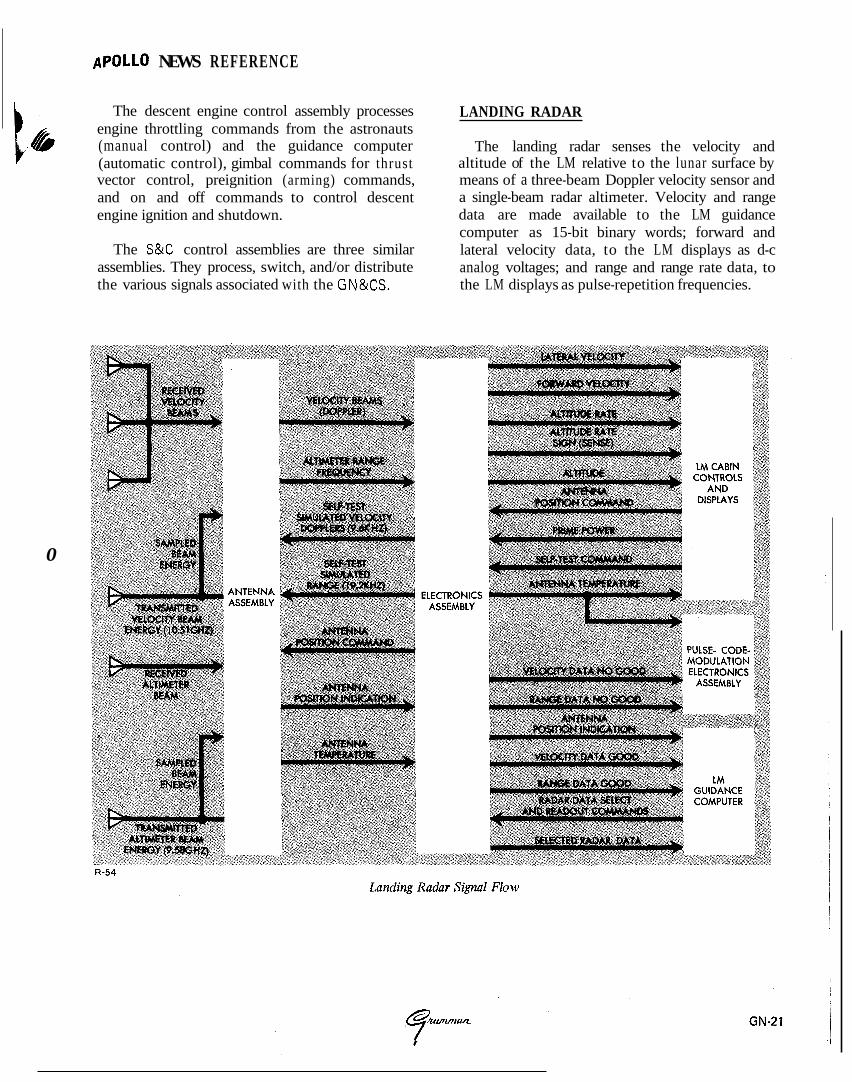
The landing radar senses the velocity and altitude of the LM relative to the lunar surface by means of a three-beam Doppler velocity sensor and a single-beam radar altimeter. Velocity and range data are made available to the LM guidance computer as 15-bit binary words; forward and lateral velocity data, to the LM displays as d-c analog voltages; and range and range rate data, to the LM displays as pulse-repetition frequencies.
APOLLO N E W S REFERENCE
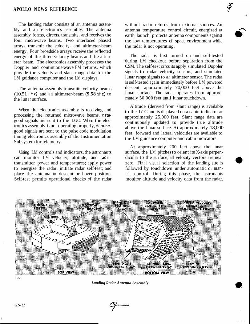
The landing radar consists of an antenna assem- bly and an electronics assembly. The antenna assembly forms, directs, transmits, and receives the four microwave beams. Two interlaced phased arrays transmit the velocity- and altimeter-beam energy. Four broadside arrays receive the reflected energy of the three velocity beams and the altim- eter beam. The electronics assembly processes the Doppler and continuous-wave FM returns, which provide the velocity and slant range data for the LM guidance computer and the LM displays.
The antenna assembly transmits velocity beams (10.51 gHz) and an altimeter-beam (9.58 gHz) to the lunar surface.
When the electronics assembly is receiving and processing the returned microwave beams, data- good signals are sent to the LGC. When the elec- tronics assembly is not operating properly, data-no- good signals are sent to the pulse code modulation timing electronics assembly of the Instrumentation Subsystem for telemetry.
Using LM controls and indicators, the astronauts can monitor LM velocity, altitude, and radar- transmitter power and temperatures; apply power to energize the radar; initiate radar self-test; and place the antenna in descent or hover position. Self-test permits operational checks of the radar
without radar returns from external sources. An antenna temperature control circuit, energized at earth launch, protects antenna components against the low temperatures of space environment while the radar is not operating.
The radar is first turned on and self-tested during LM checkout before separation from the CSM. The self-test circuits apply simulated Doppler signals to radar velocity sensors, and simulated lunar range signals to an altimeter sensor. The radar is self-tested again immediately before LM powered descent, approximately 70,000 feet above the lunar surface. The radar operates from approxi- mately 50,000 feet until lunar touchdown.
Altitude (derived from slant range) is available to the LGC and is displayed on a cabin indicator a t approximately 25,000 feet. Slant range data are continuously updated to provide true altitude above the lunar surface. At approximately 18,000 feet, forward and lateral velocities are available to the LM guidance computer and cabin indicators.
A t approximately 200 feet above the lunar surface, the LM pitches to orient its X-axis perpen- dicular to the surface; all velocity vectors are near zero. Final visual selection of the landing site is followed by touchdown under automatic or man- ual control. During this phase, the astronauts monitor altitude and velocity data from the radar.
R-55
Landing Radar Antenna Assembly
GN-22
' 9 %' APOLLO NEWS R E F E R E N C E
c, I
PRIMARY GUIDANCE PATH
The primary guidance path comprises the primary guidance and navigation section, control electronics section, landing radar, and rendezvous radar and the selected propulsion section required to perform the desired maneuvers. The control electronics section routes flight control commands from the primary guidance and navigation section and applies them to the descent or ascent engine, and the appropriate thrusters.
INERTIAL ALIGNMENT
Inertial subsection operation can be initiated automatically by the primary guidance computer or manually by the astronaut, using DSKY entries to command the computer. The inertial sub- section status or mode of operation is displayed on the DSKY as determined by a computer program. When the inertial subsection is powered up, the gimbals of the inertial measurement unit
', f are driven to zero by a reference voltage and the
coupling data unit is initialized to accept inertial subsection data. During this period, there is a 90-second delay before power is applied to the accelerometers. This is to prevent them from torquing before the gyros reach synchronous rotor speed.
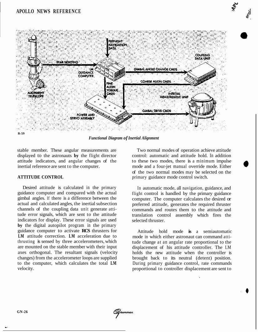
The stable member of the inertial measurement unit must be aligned with respect to the reference coordinate frame each time the inertial subsection is powered up. During flight the stable member may be periodically realigned because it may deviate from its alignment, due to gyro drift. Also, the crew may desire a new stable member orientation. The alignment orientation may be that of the CSM or that defined by the thrusting programs within the computer.
Inertial subsection alignment is accomplished in two steps: coarse alignment and fine alignment. To initiate coarse alignment, the astronaut selects, by a DSKY entry, a program that determines stable members orientation, and a coarse-alignment routine. The computer sends digital pulses, repre- senting the required amount of change in gimbal angle, to the coupling data unit. The coupling data uni t converts these digital pulses to analog signals which drive torque motors in the inertial measure- ment unit. As the gimbal angle changes, a gimbal resolver signal is applied to the coupling data unit, where it is converted to digital pulses. These digital pulses cancel the computer pulses stored in the coupling data unit. When this is accomplished, coarse alignment is completed and the astronaut can now select an in-flight fine-alignment routine.
To perform the fine-alignment routine, the astronaut must use the alignment optical telescope to sight on a t least two stars. The gimbals, having been coarse aligned, are relatively close to their preferred angles. The computer issues fine- alignment torquing signals to the inertial measure- ment uni t after it processes star-sighting data t h a t have been combined with known gimbal angles.
Once the inertial subsection is energized and aligned, LM rotation is about the gimbaled stable member, which remains fixed in space. Resolvers mounted on the gimbal axes act as angle-sensing devices and measure attitude with respect to the
GN-25
APOLLO NEWS REFERENCE 5f
R-59
Functional Diagram of Inertial Alignment
stable member. These angular measurements are Two normal modes of operation achieve attitude displayed to the astronauts by the flight director control: automatic and attitude hold. In addition attitude indicators, and angular changes of the to these two modes, there is a minimum impulse inertial reference are sent to the computer. mode and a four-jet manual override mode. Either
of the two normal modes may be selected on the ATTITUDE CONTROL primary guidance mode control switch.
Desired attitude is calculated in the primary guidance computer and compared with the actual gimbal angles. If there is a difference between the actual and calculated angles, the inertial subsection channels of the coupling data uni t generate atti- tude error signals, which are sent to the attitude indicators for display. These error signals are used by the digital autopilot program in the primary guidance computer to activate RCS thrusters for LM attitude correction. LM acceleration due to thrusting is sensed by three accelerometers, which are mounted on the stable member with their input axes orthogonal. The resultant signals (velocity changes) from the accelerometer loops are supplied to the computer, which calculates the total LM velocity.
In automatic mode, all navigation, guidance, and flight control is handled by the primary guidance computer. The computer calculates the desired or preferred attitude, generates the required thruster commands and routes them to the attitude and translation control assembly which fires the selected thruster.
Attitude hold mode is a semiautomatic mode in which either astronaut can command atti- tude change a t an angular rate proportional to the displacement of his attitude controller. The LM holds the new attitude when the controller is brought back to its neutral (detent) position. During primary guidance control, rate commands proportional to controller displacement are sent to
GN-26
t
.APOLLO N E W S REFERENCE
engine ignition after coasting phases. Manual con- trol during primary guidance control consists of on and off commands generated by the astronaut using his thrust/translation controller. These com- mands are routed through the computer to the attitude and translation control assembly to fire the proper thrusters. Translation along the +X-axis can also be initiated by the astronaut using a push- button switch tha t actuates the secondary solenoid coils of the four downward firing thrusters.
~ '@
I
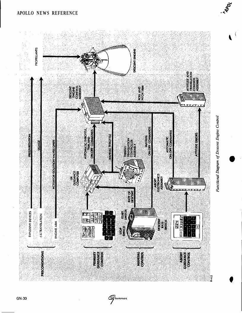
DESCENT ENGINE CONTROL
Descent engine ignition is controlled either auto- matically by the primary guidance and navigation section, or manually through the control electro- nics section. Before ignition can occur, the engine arm switch must be set to the descent engine position. This opens the pre-valves to allow fuel and oxidizer to reach the propellant shutoff valves, arming the descent engine.
Engine-on commands from either computer are routed to the descent engine control assembly which commands the descent engine on by opening 0 the propellant shutoff valves. The engine remains on until an engine-off discrete is initiated by the astronauts with either of two engine stop push- buttons or by the computer. When the LM reaches the hover point where the lunar contact probes touch the lunar surface, a blue lunar contact light is illuminated. This indicates to the astronauts that the engine should be shut down. From this point (approximately 5 feet above the lunar surface), the LM free-falls to the lunar surface.
Descent engine throttling can be controlled by the primary guidance and navigation section and/or the astronauts. Automatic increase or decrease sig- nals from the guidance computer are sent to the descent engine control assembly. An analog output from the control assembly corresponds to the per- centage of thrust desired. The engine is control- lable from 10% of thrust to a maximum of 92.5%. There are two thrust control modes: automatic and manual. In the automatic mode, the astronaut can use the selected thrust/translation controller to increase descent engine thrust only. During this mode, manual commands by the astronaut are used
to override the throttle commands generated by the computer. In the manual mode, the astronauts have complete control over descent engine thrust.
Descent engine tr im is automatically controlled during primary control, to compensate for center- of-gravity offsets due to propellant depletion and, in some cases for attitude control. The primary guidance computer routes trim commands for the pitch and roll axes. These signals drive a pair of gimbal drive actuators. These actuators, which are screwjack devices, tilt the descent engine along the Y-axis and Z-axis a maximum of +6" or-6' from the X-axis.
ASCENT ENGINE CONTROL
Ascent engine ignition and shutdown can be initiated automatically by the primary guidance computer or manually by the astronauts. Auto- matic and manual commands are routed to the S&C control assemblies. These assemblies provide logically ordered control of LM staging and engine on and off commands. A portion of the S&C con- trol assemblies, devoted to ascent engine control, is designated as the ascent engine latching device. This device provides a positive on command for fail-safe purposes if the engine-on command is interrupted. The control assemblies are enabled "
when the astronauts select the ascent engine posi- tion of the engine arm switch.
In an abort stage situation while the descent engine is firing, the control assemblies provide a time delay before commanding staging and ascent engine ignition. The time delay ensures that descent engine thrusting has completely stopped before staging occurs.
ABORT GUIDANCE PATH
The abort guidance path comprises the abort guidance section, control electronics section, and the selected propulsion section. The abort guidance path performs all inertial guidance and navigation functions necessary to effect a safe orbit or rendez- vous with the CSM. The stabilization and control functions are performed by analog computation techniques, in the control electronics section.
GN-29
APOLLO N E W S REFERENCE
- ~ A P O L L O NEWS REFERENCE
In addition, each of the functions has a relative priority with respect to the others; also within each there are a number of processing functions, each having a priority level relative to the other in the group. Most of the processing performed by the computer is in the program controlled processing category. During this processing the computer is controlled by the program stored in its memory.
Real time, which is used in solving guidance and navigation problems, is maintained within the com- puter's memory. A 745.65-hour (approximately 31 days) clock is provided. The clock is synchronized with ground elapsed time (GET) which is "time zero" at launch. This time is transmitted once every second by downlink operation for compari- son with MSFN elapsed time.
Incremental transmissions occur in the form of pulse bursts from the output channels to the coupling data unit, the gyro fine-alignment elec- tronics, the RCS, and the radars. The number of pulses and the time a t which they occur are con- trolled by the program. Discrete outputs, ori- ginating in the output channels under program control, are sent to the DSKY and other sub- systems. A continuous pulse train a t 1.024 mHz originates in the timing output logic and is sent as a synchronization signal to the timing elec- tronics assembly in the Instrumentation Subsystem (IS).
The uplink word from MSFN via the digital up- link assembly is supplied as an incremental pulse to the priority control. As this word is received, priority produces the address of the uplink counter in memory and requests the sequence generator to execute the instructions tha t perform the serial-to- parallel conversion of the input word. When the conversion is completed, the parallel word is trans- ferred to a storage location in memory by the uplink priority program. The uplink priority program also retains the parallel word for sub- sequent downlink transmission. Another program
converts the parallel word to a coded display format and transfers the display information to the DS KY.
The downlink operation is asynchronous with respect to the IS. The IS supplies all the timing signals necessary for the downlink operation.
Through the DSKY, the astronaut can load information into the computer, retrieve and dis- play information contained in the computer, and initiate any program stored in memory. A key code is assigned to each keyboard pushbutton. When a DSKY pushbutton is pressed, the key code is sent to an input channel of the computer. A number of key codes are required to specify an address or a data word. The initiated program also converts the keyboard information to a coded display format, which is transferred by another program to an output channel and to the DSKY for display. The display is a visual indication that the key code was received, decoded, and processed properly.
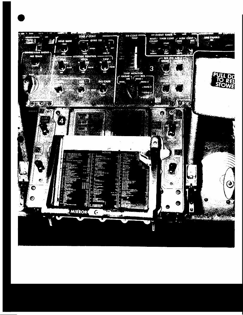
DISPLAY AND KEYBOARD
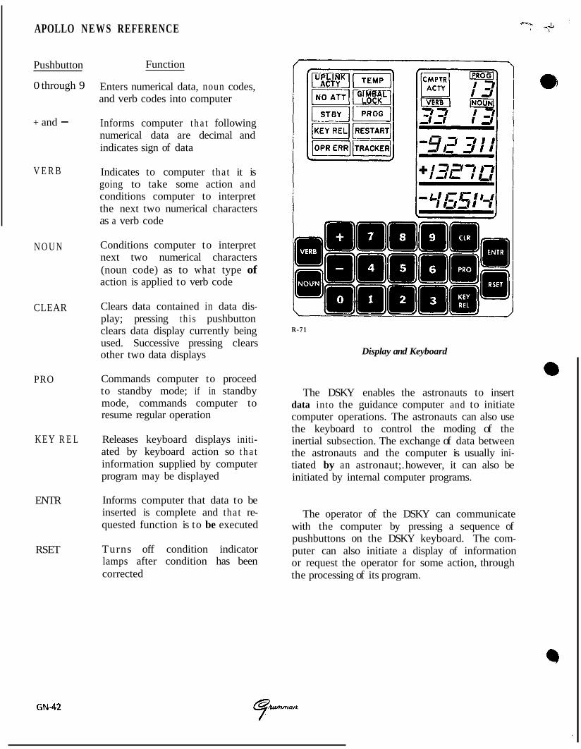
The DSKY is located on panel 4 between the Commander and LM Pilot and above the forward hatch. The upper half is the display portion; the lower half comprises the keyboard. The display portion contains five caution indicators, six status indicators, seven operation display indicators, and three data display indicators. These displays pro- vide visual indications of data being loaded in the computer, the computer's condition and the program being used. The displays also provide the computer with a means of displaying or requesting data.
The caution indicators when on, are yellow; the status indicators, white. The operation and data displays are illuminated green when ener- gized. The words "PROG," "VERB," and " NOUN" and the lines separating the three groups of display indicators, and the 19 push- buttons of the keyboard are illuminated when the guidance computer is powered-up.
GN-41
APOLLO N E W S REFERENCE
Pushbutton
0 through 9
+ and -
V E R B
N O U N
CLEAR
PRO
KEY R E L
ENTR
RSET
Function
Enters numerical data, noun codes, and verb codes into computer
Informs computer t h a t following numerical data are decimal and indicates sign of data
Indicates to computer that it is going to take some action and conditions computer to interpret the next two numerical characters as a verb code
Conditions computer to interpret next two numerical characters (noun code) as to what type of action is applied to verb code
Clears data contained in data dis- play; pressing this pushbutton clears data display currently being used. Successive pressing clears other two data displays
Commands computer to proceed to standby mode; if in standby mode, commands computer to resume regular operation
Releases keyboard displays initi- ated by keyboard action so t h a t information supplied by computer program may be displayed
Informs computer that data to be inserted is complete and that re- quested function is to be executed
Turns off condition indicator lamps after condition has been corrected
R-71
Display and Keyboard
The DSKY enables the astronauts to insert data into the guidance computer and to initiate computer operations. The astronauts can also use the keyboard to control the moding of the inertial subsection. The exchange of data between the astronauts and the computer is usually ini- tiated by an astronaut;. however, it can also be initiated by internal computer programs.
The operator of the DSKY can communicate with the computer by pressing a sequence of pushbuttons on the DSKY keyboard. The com- puter can also initiate a display of information or request the operator for some action, through the processing of its program.
GN-42 ?”