apollo - klabs.orgklabs.org/history/history_docs/mit_docs/1709.pdf · apollo guidance and...
TRANSCRIPT


APOLLO
GUIDANCE AND NAVIGATION SYSTEM
LUNAR MODULE
STUDENT STUDY GUIDE
PRIMARY GUIDANCE, NAVIGATION AND CONTROL
SYSTEM COURSE 3100
COMPUTER UTILITY PROGRAMS C3100
PREPARED BY
AC ELECTRONICS
DIVISION OF GENERAL MOTORS
MILWAUKEE, WISCONSIN
15 JANUARY 1967
PREFACE
This student study guide has been prepared by AC Electronics in responee to:
Contract NAS 9-497
for
System Assembly and Test, Inertial
Meaeurement Unit, Coupling Display Unit
Power and Servo Assembly - Project APOLLO
0 This study guide contains training material and should be used for instruction purposes only.

TABLE OF CONTENTS
Page
1-1/95 1-1
Section I General Computer Programming Concepts
Block 1 . 1 The Development of the Computer Program
Block 1 . 2 The Computer's Real Time Environment
Block 1 .3 Time Sharing the Computer Hardware
Block 1 . 4 Implementing the Time Sharing of the Computer 1.4. 1 Counter Interrupts 1.4. 2 Program Interrupts 1 . 4 . 3 Program Controlled Processing
Block 1. 5 Relative Priorities of the Types of Processing
Block 1.6 Scheduling and Execution of Program Controlled Processing on the Basis of Program Priority
1.6.1 Introduction 1 . 6 . 2 Terminology 1 . 6 . 3 Scheduling 1 . 6 . 4 Execution Control 1.6. 5 Core Set Areas and VAC Areas
1.6 . 5. 1 Core Set Areas 1 .6 .5 .2 VAC Areas
Block 1 . 7 Scheduling and Execution of Time Dependent Processing 1 . 7 . 1 Introduction 1.7 .2 Implementing Time Dependent Functions 1 . 7 . 3 Scheduling of Time Dependent Functions 1. 7 . 4 Execution of Time Dependent Functions
Block 1 .8 LGC Input and Output Channel Interface 1. 8. 1 Channel 01 1. 8 .2 Channel 02 1.8.3 Channel 03 High-Order Scaler 1 . 8 . 4 Channel 04 bw-Order Scaler 1.8.5 Output Channel 05 1.8.6 Output Channel 06 1 . 8 . 7 Output Channel 07 1.8. 8 Output Channel 10 1. 8 .9 Output Channel 11 1. a. 10 Output Channel 12 1.8. 11 Output Channel 13 1.8.12 Output Channel 14 1 .8 .13 Input Channel 15 1. 8. 14 Input Channel 16 1. 8. 15 Input Channels 17 through 27
1-1
1-2
1-2 1-2 1-3 1-3
1-6
1-6 1-6 1-6 1-8 1-8
1-10 1- 10 1- 10
1- 10 1-10 1- 12 1-12 1- 12
1- 13 1- 13 1- 13 1- 13 1-13 1- 13 1- 13 1- 13 1- 13 1- 14 1-14 1- 14 1- 15 1- 15 1- 15 1-15

TABLE OF CONTENTS (cont)
1 . 8 . 1 6 Input Channel 30 1. 8. 17 Input Channel 31 1 . 8 . 1 8 Input Channel 32 1 . 8 . 1 9 Input Channel 33
Block 1 . 9 Computer/DSKY - Hardware/Astronaut Relationship 1 . 9 . 1 Keyboard 1 . 9 . 2 Display Indicators 1 . 9 . 3 DSKY Condition Indicators 1 . 9 . 4 DSKY Operation
1 .9 .4 .1 Verb-Noun 1 . 9 . 4 . 2 Data Loading 1 . 9 . 4 . 3 Correcting Erroneous Data 1. 9. 4 . 4 Decimal and Octal Display and h a d i n g 1 . 9 . 4 . 5 Monitor vs. Display 1 . 9 . 4 . 6 Changing of Major Mode 1 . 9 . 4 . 7 Mode Initiation 1.0 .4 .8 ,Computer Control of the DSKY 1. 9. 4. 9 DSKY/Computer/Operator Interlocks
1. 9. 5 Verb-Noun List 1 .9 . 5. 1 Verb Codes 1.9 . 5. 2 Verb Deecription 1.9. 5 .3 Noun Codes
Block 1.10 Interrelationship of Processing Functions
Section I1 Executive Control of Computer Processing
Block 2 . 1 The Executive Routine 2. 1 . 1 FINDVAC and NOVAC Subroutines 2 . 1 . 2 Change Job Subroutine 2 . 1 . 3 End of Job, Job Sleep, and Priority Change Subroutines 2. 1 . 4 Dummy Job Subroutine 2. 1 . 5 Job Wake Subroutine
Block 2 . 2 Waitlist Routine
Block 2 . 3 TIME 3 Program Interrupt Routine (T3RUPT)
Block 2 . 4 Phase Table Maintenance Routine 2.4. 1 Phase Change and New Phase Subroutines 2 . 4 . 2 New Mode Exchange Subroutine 2 . 4 . 3 Check Major Mode Subroutine
Page
1-16 1-16 1-17 1-17
1-18 1-18 1-20 1-22 1-22 1-22 1-25 1-26 1-27 1-27 1-27 1-28 1-29 1-29 1-30 1-30 1-33 1-36
1-40
2- l/Zb 2-1 2-1 2-6 2-8
2-10 2-12
2-14
2-20
2-22 2-22 2-24 2-24

TABLE OF CONTENTS (cont)
Page
Section IU Input/Output Control Routines
Block 3 . 1 TIME 4 Counter Program Interrupt Routine (T4RUPT) 3 . 1 . 1 T4RUPT h a d In, 20, 30 MSEC RUPT, Service DSPTABS 3 .1 .2 A LTOUT 3 . 1 . 3 ALTROUT 3 . 1 . 4 RR AUT CHK (Rendezvous Radar Automatic Check) 3. 1 . 5 IMU Monitor
Block 3 .2 Downtelemetry (DNRUPT)
Block 3 .3 Keyboard and Uplink Telemetry Input Processing Program 3 . 3 . 1 DSKY and Uplink Interrupt Operation 3 . 3 . 2 The Pinball Program
3 . 3 . 2 . 1 C HARIN 3 . 3 . 2 . 2 NOUN Subroutine 3 . 3 . 2 . 3 VERB Subroutine 3 . 3 . 2 . 4 SIGN Subroutine 3 . 3 . 2 . 5 NUM Subroutine 3 . 3 . 2 . 6 CHARALRM Subroutine 3.3 . 2 . 7 ENTER Subroutine 3 . 3 . 2 . 8 Error Reset Subroutine 3 . 3 . 2 . 9 Key Release Subroutine 3 .3 .2 .10 Clear Subroutine
Block 3 . 4 ISS Mode Switching Routines 3 . 4 . 1 JSS CDU Zero 3 . 4 . 2 IMU Coarse Align 3. 4 . 3 IMU Fine Align
Block 3. 5 IMU Pulsing Routine
Block 3 . 6 AOTMARK Routine 3.6. 1 Alignment Optical Telescope (AOT) 3 . 6 . 2 Non-flight Star Sighting 3 . 6 . 3 Inflight Star Sighting 3 . 6 . 4 AOTMARK Routine
Section IV Miscellaneous Routines
Block 4.1 Program Alarm Routine
Block 4 . 2 Program Abort Routine
Block 4 . 3 Fresh Start and Restart Routine
3 - 11%'
3-1 3-2 3-7 3-7 3-7 3-8
3-40
3-48 3-49 3-53 3-53 3-53 3-65 3-65 3-66 3-67 3-67 3-69 3-69 3-69
3-70 3-70 3-70 3-76
3-79
3-86 3-86 3-86 3-86 3-88
4-1/46 4-1
4-6
4-6

TABLE OF CONTENTS (cont)
Page
Block 4 .4 Self-check Routine 4 .4 .1 Self-check Options 4.4.2 Error Detection 4.4.3 DSKY Check 4.4.4 How to Use the DSKY to Monitor Self-check 4.4.5 Self Check Flow
Appendix A
Computer Programs
Appendix B
Explanation of Sample Program Listing
Appendix C
Interpretive Programming
4-15 4-15 4-17 4-19 4-19 4-21
B - 4 4
c-1/31

Figure
1- 1 1-2 1-3 1-4
1-5 1-6 1-7 1-8 1-9 1-10 1-11 1-11A 1- 12
2-1 2-2 2-3 2-4 2-5 2-6 2-7 2-8 2-9 2- 10 2-11 2-12 2- 13 2- 14 2- 15
3- 1 3-2 3-3 3-4 3-5 3-6 3-7 3-8 3-9 3-10 3-11 3- 12 3- 13 3- 14 3- 15 3- 16 3- 17 3-18 3- 19 3-20 3-21
LIST OF ILLUSTRATIONS
Counter Interrupt Processing Program Interrupt Processing Counter and Program Interrupt Processing Control of Program Controlled Processing on Basis of Program Priority Numbers Core Set Areas of the Computer Program (Core Set List) VAC Areas of the Computer Program Channel 07 Fix Extension Bits Radar Selection Gyro Selection Display Indicators DSKY Display Relay Circuitry DSKY Display Indications Simplified Processing for Zero IMU - CDU Routine
Executive's Core Set List Executive's VAC Areas Executive's FINDVAC and NOVAC Executive's Change Job Executive's Priority Change, End of Job and Job Sleep Executive's Dummy Job Executive's Job Wake Waitlist's Waiting List Time Values Stored in List 1 Maintaining Chronological Waiting List Waitlist TIME 3 Interrupt Routine Phase Change and New Phase New Mode Exchange Check Major Mode
General T4RUPT DSPTAB Code Detailed T4RUPT Computer Interface with Telemetry Downtelemetry Transfer Downtelemetry General Computer Format Nominal Downlink List, Sunburst, Rev 14 Downrupt General Flow Diagram for Pinball INLINK Word Format KEYRUPT and UPRUPT CHARIN ISS CDU-ZERO IMU Coarse Align IMU Fine Align IMU Pulsing Generation of Merged Word LM AOT Azimuth Positions AOT Reticle Pattern Basic Inflight Star Sighting Sequence AOTMARK Routine
Page
1-4 1-5 1-7
1-9 1-11 1-11 1-14 1-14 1-15 1-21
1-22A 1-22B
1-42
2-2 2-3 2-5 2-7 2-9
2- 11 2-13 2-15 2-16 2-18 2-19 2-21 2-23 2-25 2-26
3-3 3-6
3-10 3-41 3 -42 3 -43 3-44 3-46 3-50 3-51 3-52 3-54 3-71 3-73 3-77 3-80 3-85 3-87 3-87 3-87 3-90

Fig
4- 1 4-2 4-3 4-4 4-5
4- 6 4-7 4-a
APl A-: A-: A 4 A-! A-E A-f A-7
B- :
API C-: C-; C-I
a
pure
I
I
I
I
lendix A
1 3 3 I
3 I
)
xndix B 1
lendix C
1 1 3
LIST OF ILLUSTRATIONS (cont)
Page
Program Alarm Program Abort Fresh Start and Restart Self Check Options Count Regieters and Self Check Error Detection with f 10 or -0 in SMODE Self Check Error Detection with *l - kt7 in SMODE Self Check with * 11 in SMODE Self Check
SQ Register Memory to SQ Register Transfer Order Code Determination Subinstruction ADO, Data Transfer Diagram Subinstruction STDB, Data Transfer Diagram Subinstruction RSM3, Data Transfer Diagram Subinstruction NDXO, with implied Address Code RESUME, Data Transfer Magram
Sample Program Listing
Network Mapping Symbols Interpretive Routing Flowgram Ynterpretive Program Flow
4- 2 4- 7 4- 8
4- 16
4- 18 4-20 4-20 4-2 a
A- 2 A- 11 A- 12 A- 15 A- 16 A- 17
A- 18
B- 1
c-7 C-8
c- 12
Table
1-1 1-2 1-3 1-4 1-5
3-1 3-2 3-3 3-4
4-1 4-2 4-3
Appendix A
A- 1 A-2 A-3
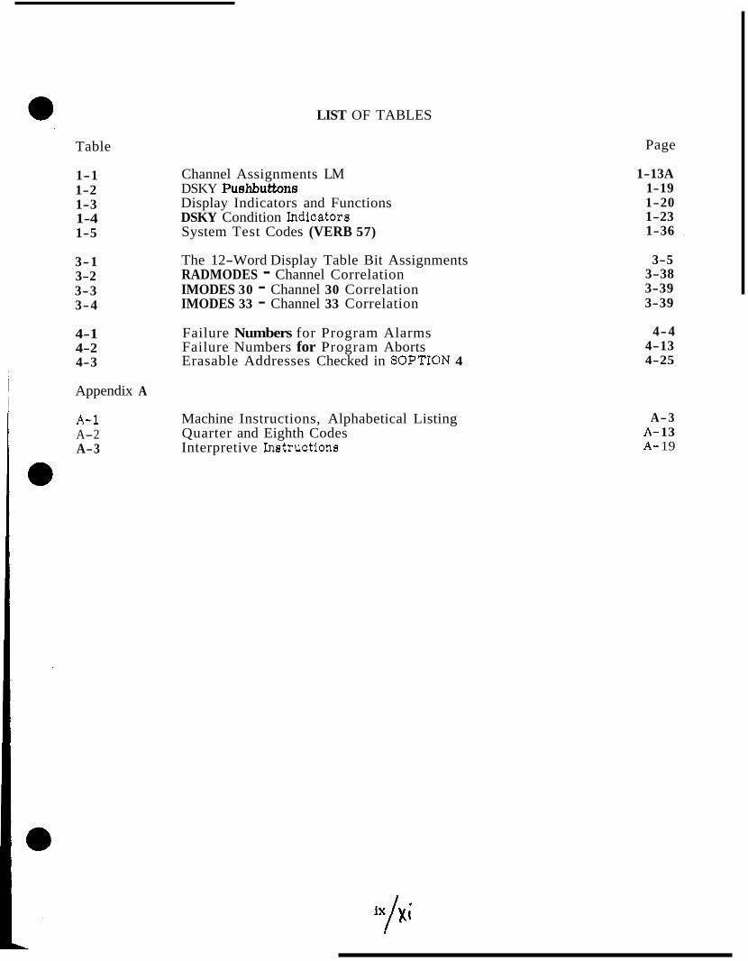
LIST OF TABLES
Page
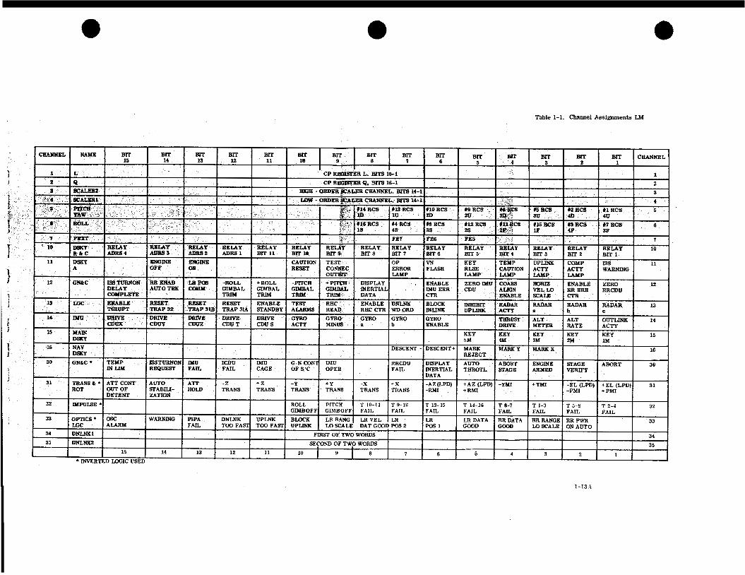
Channel Assignments LM DSKY Puehbuttons Display Indicators and Functions DSKY Condition Indicators System Test Codes (VERB 57)
The 12-Word Display Table Bit Assignments RADMODES - Channel Correlation IMODES 30 - Channel 30 Correlation IMODES 33 - Channel 33 Correlation
Failure Numbers for Program Alarms Failure Numbers for Program Aborts Erasable Addresses Checked in SOPTION 4
Machine Instructions, Alphabetical Listing Quarter and Eighth Codes Interpretive Instructions
1-13A 1-19 1-20 1-23 1-36 ,
3-5 3-38 3-39 3-39
4-4 4-13 4-25
A-3 A- 13 A- 19


OBJECTIVES
The intent of this study guide is to give the student an understanding of the basic utility programming concepts associated with the LM computer. The programs described in this study guide a re utility programs which, for the most part, are used in conjunction with all computer operations and include the basic executive routines, input/output routines and miscellaneous service routines along with basic programming techniques.
This study guide is organized in the sequence of instruction of the course and is divided into four major sections. Each of these sections is associated with the LM peculiar programs.
The objectives of this study guide are to provide the student with:
a. Course materials organized in the sequence of classroom presentation for self-study.
b. A familiarity of the overall utility programs associated with the LM computer.
REFERENCES
The following documents were used in preparation of this study guide:
Digital Development Operating Procedures for AGC Block I1 Self Check and Report 9 Show-Banksum
Revision 14 of Program SUNBURST Dated 9 September 1966
ND-1021042 Apollo Lunar Excursion Module Primary Guidance, Navigation, and Control System
Digital Development Block I1 Channel Assignments Memo # 254, Rev. B

SECTION I
GENERAL COMPUTER PROGRAMMING CONCEPTS
INTRODUCTION
This section presents the general programming concepts as used in the Apollo computer. Included is (1) a discussion of the development process of the computer program, ( 2 ) the real-time environment in which the computer operates, (3) time sharing of the computer among its processing functions, (4) the scheduling and implementation of program con- trolled processing functions, (5) the scheduling and implementation of time dependent program controlled processing functions, and ( 6 ) a general discussion of the computer's relationship with its hardware and human environment. Also included is (7) a brief dis- cussion of the interpretive programming technique used in the computer. \
1 .1 THE DEVELOPMENT OF THE COMPUTER PROGRAM
The development of the total program capability for the Apollo computer, has been, and will continue to be an evolutionary process. This is true because changes in hardware design, mission, interface, eta., which must be reflected in the program of the computer and also the magnitude of the job of programming the computer.
In this evolutionary process, several groups of programs have been released. Each group
programs o r routines. Also, each of the groups of programs have had many revisions to the programs contained within the group.
0 of programs has superseded the previous group and has contained more of the required
The first .major series of programs which have been released for the Block II Command Module and LM computers (CMC and LGC), was called RETREAD. Basically, RETREAD converted Block I computer utility programs to Block II language and updated the various routines. RETREAD was followed by the AURORA ( L M ) and SUNDIAL (Command Module) series of programs. These two programs built on the foundation set by RETREAD and branched out in there respective directions to encompass programs associated only with the Command Module or LM. This etudy guide is based on the Sunburst Computer Program for LM,
Future programs will be based on the foundation developed by this series of programs. Each new group of programs will add to those programs contained in its immediate predecessor reflecting changes to previous programs deemed necessary by equipment changes in the PGNCS, mission, etc. Through this progression, the final computer program will be obtained and will afford the designers, programmers and users of the PGNCS a high degree of confidence in the computer programs.
1.2 THE COMPUTER'S REAL TIME ENVIRONMENT
The computer operates within the spacecraft and specifically within the PGNCS. Various , systems on board the spacecraft interact with the computer to enable the required functions ~ to be performed, thereby enabling the mission to be accomplished. All systems within the
spacecraft operate on a real time basis, and therefore, the computer must also operate on a real time basis keeping cognizant of the happenings in this environment. Based on these 0 happenings or conditions which exist at any particular time, the computer must determine if an action is required, and if it is, what must be done.
i
1- 1

Inputs to the computer are derived from the PGNCS Inertial Subsystem, Optical Subsystem and Computer Subsystem. Also, inputs to the computer a r e derived from the Stabilization Control System, the Communication and Instrumentation System, etc. The inputs from these systems and subsystems may change at any time and the computer must be able to
' cope with them within a reasonable period of time.
Outputs from the computer are routed to the three subsystems of the PGNCS along with direct outputs to the Central Timing Equipment, Communications and Instrumentation System andto the 'Stabilization and Control System. The computer is also capable of con- trolling the outputs of the inertial subsystem of the PGNCS to the Stabilization and Control System. The outputs to these systems must correspond to the happenings o r conditions which exist at any particular time in order that the computer effectively copes with the situation and fulfills its role in the spacecraft.
1 .3 TIME SHARING THE COMPUTER HARDWARE
The computer operates in an environment in which many parameters and conditions change in a continuous manner. The computer, however, operates in a discrete, incremental manner, operating on only one item at any instant in time. Therefore, in order for the computer to process the many parameters and conditions, and perform its function in the PGNCS and spacecraft, the computer hardware must be time shared. The time sharing of the computer hardware is accomplished by assigning priorities to the various processing functions required of the computer. These priorities are used by the computer so that it 0 processes the highest priority processing function required at any particular time.
1.4 IMPLEMENTING THE TIME SHARING O F THE COMPUTER
As previously stated, the basis for the time sharing of the computer is the priority of the processing functions requiring processing. The implementation of the time sharing is accomplished through one of three methods which are:
a. A pure hardware function. (Counter interrupts)
b. A hardware and program control function. (Program interrupts)
c. A pure program control function. (Program controlled processing)
Each of these three groups has a relative priority with respect to the other groups; also, within each of the groups there a re a number of processing functions, each having a priority level relative to the other functions within the group. The majority of the processing performed by the computer falls into a pure program control processing category. In this category the computer hardware is controlled by the program stored in the computer's memory.
1.4.1 COUNTER INTERRUPTS. The processing performed by the computer which is accomplished under control of the computer hardware is referred to as a counter interrupt. This processing handles items such as A V pulses from the PIPA'S, A 8 pulses from the CDU's, L! time pulses from the computer timing circuitry, and control pulse outputs from the computer used to position the stable member of the IMU.
1-2

Whenever one of these pulse inputs is present, any other processing being performed by the computer is temporarily suspended or interrupted. Then the input pulse is pro- cessed under control of the computer hardware. After the input pulse is processed, control of the computer hardware is returned to the program controlled processing which was suspended. (See figure 1-1. ) The processing of one of these input pulses requires approximately 12 microseconds.
Through the processing of the counter interrupts, the computer accumulates data such as velocity, IMU gimbal angles, radar angles and the number of computer pulse outputs developed to position the stable member.
1.4.2 PROGRAM INTERRUPTS. The processing performed by the computer which is controlled through both circuit and program controlled processing functions is referred to as program interrupt. This type of processing is performed whenever a particular condition exists, either internal o r external to the computer. The conditions which cause a program interrupt are:
a. Timing of reaction control system.
b. Time to process a routine scheduled to be processed at a particular time.
c. Time to process a routine which performs computer input/output functions.
d. An input from the DSKY o r MARK pushbuttons. e e. Time to load a new DOWNLINK telemetry word.
f. Time to process an UPLINK word. g. Time to process an attitude or tranelation controller input. h. Time to process a radar input. The processing of one of these conditions is initiated whenever the condition exists. The initiation of the processing is accomplished by a circuit function which forces control of the computer hardware to a particular program controlled processing routine. The program controlled processing function being processed at the time when a program interrupt occurs is suspended and control of the computer is forced to the routine corresponding to the program interrupt condition which exists. (See figure 1-2. ) The program interrupt routine then processes whatever is required, depending on the program interrupt condition present. After completing the required processing for the program interrupt, control of the computer hardware is returned to the suspended program.
1.4 .3 PROGRAM CONTROLLED PROCESSING, Most of the time, the computer's hardware is controlled by the program stored in its memory. Of the many routines o r processing functions that the computer is capable of processing, some means must be employed to enable the computer to process the routines required at any one time, and to process the most important required routine first.
1- 3

A T l M E FROM TIMER m
A8 FROM ICDU's m
A@ FROM R C D U ~ m
AV FROM PIPA's U
RHC CONVERTER e COWCTER INTERWPT SEiMCE
UPLINK DATA 0
RADAR DATA e
CONTROL PULSE OUTPUTS TO IRIG's 5 CDU's
THRUST CONTROL *
LEM MONITOR (SPARE) m
DOWNLINK Ir
CONTROL PULSE OUTPUTS TO ALT/ALT RATE METER
COMPUTER em nmow- U U U : USAGE TO
PROGRAY CONTROL
17502
Figure 1-1. Counter Interrupt Processing

TIME DEPENDENT TASK CONTROL
TIME FOfl INPUT/ OUTPUT
KEYBOARD INPUT INTERRUm SERVICE
MARK ,-I DOWNLINK TELEM. WORD REQUIRED I UPLINK WORD ASSEMBLED
ATTITUDE OR TRANSLATION CONTROLLER
RADAR DATA
P R o c l u y CL)CJTFWLLED ."""" *
FOUCED SUSPENSION pcIoc~:ssIm OF PROGRAM CONTROLLED PROCESSING
r 1
COMPUTER HARDWARE W E
I
Figure 1-2. Program Interrupt Processing
RRWIN HI" USAGE TO PFIOGRAY CONTROL
17583
In order for a routine or program controlled processing function to be performed, it must first be scheduled. The scheduling of a particular routine o r processing function is a function of another routine o r processing function. The scheduling also can be initiated through the DSKY. At the present time, the computer is capable of having upto seven routines, usually referred to as ttjobstf, scheduled to be done at one time. The job which is processed out of the possible aeven scheduled job8 is determined by the priority numbers assigned to the jobs. If a job is scheduled having a priority higher than the job being processed, the computer suspends the processing of the lower priority job and processes the higher priority job. When the higher priority job is completed, the control of the complter hardware returns to the lower priority job at the point where it was suspended. Using the scheduling of jobs and the priority assigned to the various jobs, the most important program controlled processing function is performed at any time.
1 . 5 RELATIVE PRIORITIES OF THE TYPES O F PROCESSING
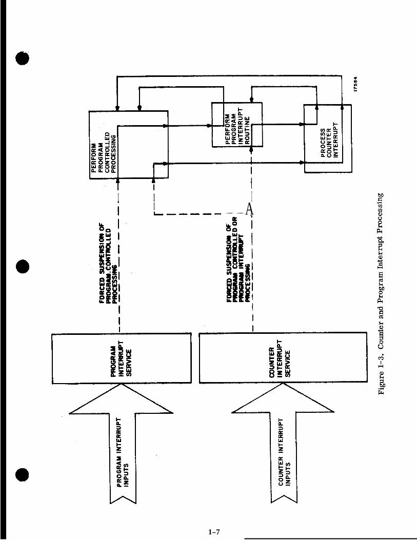
A s previously stated, each of the three types of processing (counter interrupt, program interrupt and program controlled processing) have relative priorities. Of the three types, the counter interrupt processing is the highest priority processing function. A counter interrupt input, which requires processing, causes the processing of either a program controlled function or program interrupt to be suspended. After processing the counter interrupt, control is returned to the processing which was suspended. (See figure 1-3.)
Program interrupts are the next highest priority type of processing. This type of pro- cessing causes the suspension of any program controlled processing. A program interrupt cannot interrupt o r suspend the processing of a counter interrupt or the processing of another program interrupt. However, through program action, an inhibit can be set so that the program interrupt processing cannot interrupt the program controlled processing.
The program controlled processing is the lowest priority type of processing. Any counter interrupt o r program interrupt processing causes the program controlled processing to be suspended. The exception to this, a s stated above, is when the honoring of a program interrupt is inhibited through program action. The program interrupts would be inhibited if some fairly critical function was being performed through program controlled processing.
1.6 SCHEDULING AND EXECUTION O F PROGRAM CONTROLLED PROCESSING ON THE BASIS O F PROGRAM PRIORITY
1 .6 .1 INTRODUCTION. The processing of program controlled processing functions, as previously stated, is controlled on the basis of the priority assigned to the pro- cessing functions. However, a program controlled processing function cannot be processed unless it has been scheduled. In the following paragraphs, the scheduling and control of program controlled processing functions is discussed.
1.6 .2 TERMINOLOGY. Prog-ram controlled processing function is a term which has been used up to this point in the study guide to refer to program routines, subroutines, etc., which control the processing of various functions. Any one of these categories can be scheduled to be processed on a priority basis. These programs, routines,
. etc. , which require scheduling in order to be processed a r e referred to as JOBS.
1-6
I I I I L”“- ” A
1-7
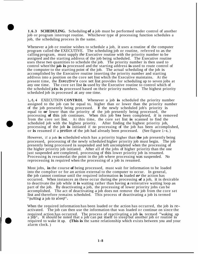
e 1.6 .3 SCHEDULING. Scheduling of a job must be performed under control of another job or program interrupt routine. Whichever type of processing function schedules a job, the scheduling process is the same.
Whenever a job o r routine wishes to schedule a job, it uses a routine of the computer program called the EXECUTIVE. The scheduling job or routine, referred to as the calling program, must supply the Executive routine with the priority number to be assigned and the starting address of the job being scheduled. The Executive routine uses these two quantities to schedule the job. The priority number is then used to control when'the job is processed and the starting address is used to route control of the computer to the starting point of the job. The actual scheduling of the job is accomplished by the Executive routine inserting the priority number and starting address into a position on the core set list which the Executive maintains. At the present time, the Executivefs core set list provides for scheduling up to seven jobs at any one time. The core set list is used by the Executive routine to control which of the scheduled jobs is processed based on their priority numbers. The highest priority scheduled job is processed at any one time.
1.6.4 EXECUTION CONTROL Whenever a job is scheduled the priority number assigned to the job can be equal to, higher than or lower than the priority number of the job presently being processed. If the newly scheduled job's priority is equal to or lower than the priority of the job presently being processed, the processing of this job continues. When this job ha8 been completed, it is removed from the core set list. A t this time, the core set list is scanned to find the scheduled job with the highest priority. After finding the highest priority job, processing of the job is initiated if no processing of the job has been accomplished, or is resumed if a protion of the job had already been processed. (See figure 1-4. )
However, i f a job is scheduled which has a priority higher than the job presently being processed, processing of the newly scheduled higher priority job must begin. The job presently being processed is suspended and left uncompleted when the processing of the higher priority job initiated. After all of the jobs of higher priority than the one just suspended are completed, processing of this lower priority job is resumed. Processing is resumedat the point in the job where processing was suspended. No reprocessing is required when the processing of a job is resumed.
Most jobs, in the course of being processed, must wait for information to be loaded into the complter o r for an action external to the computer to occur. In general, the job cannot continue until the required information is loaded or the action has occurred. When instances as these occur during the processing of a job, it is desirable to deactivate the job while it is waiting rather than having a reiterative waiting loop as part of the job. By deactivating a job, the processing of lower priority jobs can be accomplished. The act of deactivating a job does not remove the job from the core set list and therefore remains scheduled. This process of deactivating a job is termed '"putting a job to sleep".
I When the required information has been loaded or the action has occurred, the job is re-
~ required action has occurred. The process of reactivating a job is termed "waking up activated. The job can then use the information that was loaded o r continue on since the
a job". It should be noted that a job can put itself to sleep but another job o r routine is required to wake it up. (This is the same relationship which exists between you and your alarm clock. )
1-8

JOB 'A' PRIORITY "BER IO SCHEW&E JOB 'e' WITH eRHwTv MJM6ER IS
JOB'A' IS NOT HIGHEST PRIORITY TRANSFER CONTROL T O EXECUTIVE CONTROL
IF JOB 'A' IS HIGHEST PRIORITY JOB, PROCESSING RESUMES A T POINT IN ROUTINE WHERE PROCESSING WAS S U S P E N D E D
WHEN JOB'B' IS C O M P L E T E D C O N T R O L RETURNED To MOCUflVE COUTROL 17585
Figure 1-4. Control of Program Controlled Processing on Basis of Program Priority Numbers

1 . 6 . 5 CORE SET AREAS AND VAC AREAS. The capability of the computer to suspend and deactivate jobs and resume processing at the point where they were suspended or deactivated is made possible by the storage provided by the CORE SET AREAS and VAC AREAS (Vector Accumulator Area). These two areas provide storage for the informa- tion of a job while it is being processed. A CORE SET AREA or both a CORE SET AREA and a VAC AREA are reserved for use for every scheduled job. An area reserved for a particular scheduled job cannot be used by another job. Therefore, with all of the information being processed by a job stored in the reserved CORE SET and VAC areas, a job can be suspended o r deactivated and the processing can be resumed at the point in the job where it was suspended o r deactivated.
1.6.5.1 Core Set Areas. The CORE SET AREAS of the computer program are an integral part of the core set list. Each of the seven CORE SET AREAS consists of twelve sequential memory registers. One of the twelve is used for storing the priority number and the VAC address associated with the job. The priority in this register signifies that the CORE SET AREA is reserved. A mem- ory register used for storing the starting address of the job, when the job is originally scheduled, will store the resumption address of a job which has been suspended or deactivated. The other memory registers are used to store infor- mation concerned with the job using the CORE SET AREA. (See figure 1-5. )
1 .6 .5 .2 VAC Areas. Some jobs o r programs of the computer require more storage capability than is provided by the core set area. One type of job which requires more storage a re those jobs involved with the processing of vector quantities. Double o r triple precision? three component representation is used for most vector quantities in the computer. (Double and triple precision repre- sentation uses two o r three computer words to represent one quantity. ) Therefore, vector quantities require up to nine memory registers for storage. Besides the vector quantity, other information associated with a particular job must be stored. In order to meet the storage capacity required for these type of jobs, an additional block of memory registers can be reserved for a job. The computer program now provides for five blocks, with each block containing 44 memory registers. These blocks of memory registers a re called VECTOR ACCUMULATOR AREAS or , in short, VAC AREAS. If a VAC AREA is required by a job, one of the five is reserved for the job along with one of the CORE SET AREAS. (See figure 1-6. )
Again, since a particular VAC AREA is reserved for use by a particular job, and since information being processed by the job is stored in the VAC AREA and CORE SET AREA, the processing of a job can be resumed at the point in the processing where it was suspended o r deactivated. It should also be noted that with the seven CORE SET AREAS and the five VAC AREAS, sufficient scheduling and storage capacity is provided to handle the processing loads imposed on the computer.
1 . 7 SCHEDULING AND EXECUTION O F TIME DEPENDENT PROCESSING
1 .7 .1 INTRODUCTION. Some processing functions and corresponding output functions of the computer require a rather stringent consideration of time. In order to accommo- date this consideration, a job or routine which controls a processing o r output function must be initiated at a specific time. This could be accomplished by having incorporated,
1- 10

CORE SET 60
CORE SET 61
CORE SET IC6
CORE SET 85
ADDRESS, ETC. CORE SET #4
- THE REMAINING FIVE MEMORY REGISTERS ARE USED TO CORE SET 63
JOB USING THE CORE SET AREA. CORE SET 62
MEMORY REGISTERS, SEVEN OF WHICH ARE USED FOR - EACH CORE SET AREA CONSISTS OF TWELVE (DECIMAL)
STORAGE OF QUANTITIES PERTAINING TO THE SCHEDULED
k
STORE INFORMATION ABOUT THE JOB; PRIORITY, STARTING
.
Figure 1-5. Core Set Areas of the Computer Program (Core Set List)
VAC AREA #1
VAC AREA #2
VAC AREA #3
VAC AREA #4
VAC AREA #5
- A VAC AREA (VECTOR ACCUMULATOR) PROVIDES 44 (DECIMAL) MEMORY REGISTERS FOR STORAGE OR INFORMATION PERTAINING TO THE JOB FOR WHICH IT WAS RESERVED.
- JOB, ESPECIALLY THOSE INVOLVING VECTOR QUANTITIES REQUIRE MORE STORAGE CAPACITY THAN IS AFFORDED BY THE CORE SET AREAS
- IF A VAC AREA IS REQUIRED FOR A JOB, BOTH A VAC AREA AND A CORE SET AREA MUST BE RESERVED FOR THE JOB.
Figure 1-6. VAC Areas of the Computer Program
1- 11
as part of a job, a waiting loop which would continuously look at the computer's real time reference, TIME 1 and TIME 2 counters. If this method was used, a considerable amount of computer time would be wasted. Another method of time scheduling and execution of functions as used in the computer is discussed in general terms in this portion of the study guide.
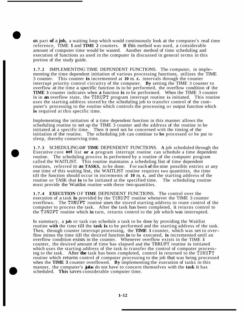
1 . 7 . 2 IMPLEMENTING TIME DEPENDENT FUNCTIONS. The computer, in imple- menting the time dependent initiation of various processing functions, utilizes the TIME 3 counter. This counter is incremented at 10 m. s . intervals through the counter interrupt priority control circuitry of the computer. By setting the TIME 3 counter to overflow at the time a specific function is to be performed, the overflow condition of the TIME 3 counter indicates when a function is to be performed. When the TIME 3 counter is in an overflow state, the T3RUPT program interrupt routine is initiated. This routine uses the starting address stored by the scheduling job to transfer control of the com- puter's processing to the routine which controls the processing o r output function which is required a t this specific time.
Implementing the initiation of a time dependent function in this manner allows the scheduling routine to set up the TIME 3 counter and the address of the routine to be initiated at a specific time. Then it need not be concerned with the timing of the initiation of the routine. The scheduling job can continue to be processed o r be put to sleep, thereby conserving time.
1 . 7 . 3 SCHEDULING OF TIME DEPENDENT FUNCTIONS. A job scheduled through the Executive core set list or a program interrupt routine can schedule a time dependent routine. The scheduling process is performed by a routine of the computer program called the WAITLIST. This routine maintains a scheduling list of time dependent routines, referred to as TASKS, to be done. For each of the nine possible entries at any one time of this waiting list, the WAITLIST routine requires two quantities, the time till the function should occur in increments of 10 m. s . and the starting address of the routine or TASK that is to be initiated at the specified time. The scheduling routine must provide the Waitlist routine with these two quantities.
1 .7 .4 EXECUTION O F TIME DEPENDENT FUNCTIONS. The control over the execution of a task is provided by the T3RUPT routine whenever the TIME 3 counter overflows. The T3RUPT routine uses the stored starting address to route control of the computer to process the task. After the task has been completed, it returns control to the T3RUPT routine which in turn, returns control to the job which was interrupted.
In summary, a job or task can schedule a task to be done by providing the Waitlist routine with the time till the task is to be performed and the starting address of the task. Then, through counter interrupt processing, the TIME 3 counter, which was set to over- flow minus the time till the desired function is to be executed, is incremented until an overflow condition exists in the counter. Whenever overflow exists in the TIME 3 counter, the desired amount of time has elapsed and the TBRUPT routine is initiated which uses the starting address of the task to transfer the control of computer process- ing to the task. After the task has been completed, control is returned to the T3RUPT routine which returns control of computer processing to the job that was being processed when the TIME 3 counter overflowed. By implementing the execution of tasks in this manner, the computer's jobs do not have to concern themselves with the task it has scheduled. This saves considerable computer time.
1- 12

1 . 8 LGC INPUT AND OUTPUT CHANNEL INTERFACE
In addition to the counter interrupt and the program interrupts previously dt-!scrjGt.!d, tht: LGC has a number of other inputs derived from its interfacing hardware. These itlpu.t.s arc! a result of the functioning of the hardware o r an action by the operator oi the spacecraft. The counter interrupts in most cases enable the LGC to process inputs representative of data parameters such as changes in velocity. The program interrupt inputs tcj ine IdC;C arc used to initiate processing of functions which must be processed a relatively short tlrne after B particular function is present. The other inputs to the LGC, in general, LXI:LG~C thc LGC to be cognizant of "conditions" which exist in its environment. These inputs a r c routed to, and are available to the LGC's programs through the LGC's input registers.
The outputs of the LGC fall in one of the following categories: (1) data., (2) corltrol, ( 3 ) condition indications. Some of these outputs are controllable through thc LGC's program while others are present as a function of the LGC circuitry. All of the outputs which a r e controlled by the LGC's programs are developed through the LGC's output ref,ist.crs. The bit breakdown per channel is shown in table 1-1.
1 . 8 . 1 CHANNEL 01. This channel is used a s the L register of the centrd procr?ssor.
1 . 8 . 2 CHANNEL 02. This channel is used as the Q register of the central prc)c:c?ssor.
1. 8 . 3 CHANNEL 03 HIGH-ORDER SCALER. This channel furnishes a 1 4 - I J i l p js i t ivc3 number whose least significant bit has a weight of 5. 12 seconds. The rn&~inlum cont,utlt of the register is 23.3 hours.
1. 8.4 CHANNEL 04 UIW-ORDER SCALER. This channel furnishes a l-!.--bit. positive number whose least significant bit has as a weight of 1/3200 second. 'The m:u;irnunl content of the register is 5.12 seconds.
1 .8 .5 OUTPUT CHANNEL 05. This channel has eight bit positions and is assnciattd with the reaction control system jets. The channel outputs a r e used for translational and rotational motion of the LM. The RCS jet commands from the cha.nnel a r e fed to the preamplifiers of the jet drivers in the CES. The driver ampli.fit?c o u t p u t s are then fed to the RC subsystem to provide the required control.
The first number contained in the bit positions indicates which of t h e It; thrusters is controlled by that bit. Four clusters is used. The letter indicates the direction of thrust such as U for up and D for down.
I.. 8 . 6 OUTPUT CHANNEL 0 6 . This channel has eight bit positions a.nd 1s :hci associated with the reaction control system jets. A logic one in any of thc bit fxmtions will cause the appropriate reaction control jet to be fired.
1.8.7 OUTPUT CHANNEL 07. This channel is the F EXT register. It is associated with the selection of word locations in fixed memory as shown in figure 1-7. This channel has three bit positions.
1.8.8 OUTPUT CHANNEL 10. The information contained in this channel is routed the DSKY's. The different configurations light various displays on the DSKY's. In Section N, it will be seen that there is a basic difference between the information In bit positions 1 through 11 and the information in bits 12 through 15.
1- 13
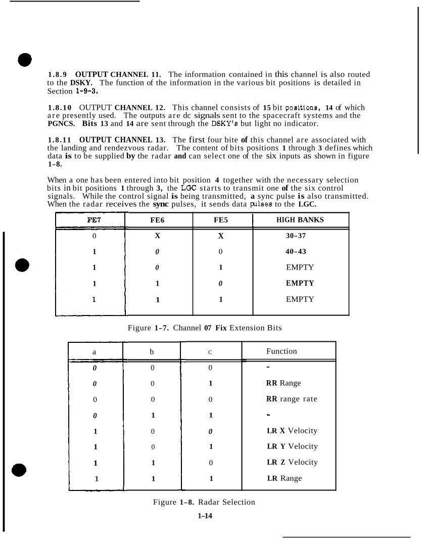
1 .8 .9 OUTPUT CHANNEL 11. The information contained in this channel is also routed to the DSKY. The function of the information in the various bit positions is detailed in Section 1-9-3.
1 .8 .10 OUTPUT CHANNEL 12. This channel consists of 15 bit positions, 14 of which a r e presently used. The outputs a re dc signals sent to the spacecraft systems and the PGNCS. Bits 13 and 14 are sent through the DSKY's but light no indicator.
1 .8 .11 OUTPUT CHANNEL 13. The first four bite of this channel a re associated with the landing and rendezvous radar. The content of bits positions 1 through 3 defines which data is to be supplied by the radar and can select one of the six inputs as shown in figure 1-8.
When a one has been entered into bit position 4 together with the necessary selection bits in bit positions 1 through 3, the LGC starts to transmit one of the six control signals. While the control signal is being transmitted, a sync pulse is also transmitted. When the radar receives the sync pulses, it sends data pllses to the LGC.
FE7
0
1
1
1
a
0
0
0
0
1
1
1
1
FE6
X
0
0
1
1
FE5 I HIGH BANKS
X
EMPTY 1
EMPTY 0
EMPTY 1
40-43 0
30-37
Figure 1-7. Channel 07 Fix Extension Bits
b
0
0
0
1
0
0
1
1
C
0
1
0
1
0
1
0
1
Function
- RR Range
RR range rate
- LR X Velocity
LR Y Velocity
LR Z Velocity
LR Range
Figure 1-8. Radar Selection
1- 14

0 Bit positions 12 through 14 have been covered under program interrupt priority control.
1.8.12 OUTPUT CHANNEL 14. The altitude meter control is controlled by bit positions 2 and 3 of output channel 14.
Bit positions 11 through 15 are associated with the CDU drive control. The CDU drive control enters the following dc signals into the counter priority control to request the execution of a DINC instruction: X IMU CDU, Y IMU CDU, Z IMU CDU, S RR CDU and T RR CDU.
Signal X IMU CDU is generated when bit position 15 contains a logic one, signal Y IMU CDU is generated when bit position 14 contains a logic one, signal Z IMU CDU when bit position 13 contains a logic one, signal T RR CDU when bit position 12 contains a logic one, and signal S RR CDU when bit position 11 contains a logic one. More than one of these signals can be generated simultaneously.
The gyro drive control selects a gyro to be torqued positively o r negatively as shown in figure 1-9 and then applies a 3200 cps to the appropriate gyro to aocomplish this function. The appropriate signal is determined by the bit configuration of bits 7 through 9 of output channel 14. If bit positions 6 and 10 a r e a logic one, a 3200 cps pulse train is routed to the gyro electronics specified by bit positions 7 through 9, and a dc signal is entered into the counter priority control which commands the sequence generator to perform a DINC instruction.
a
0 0 I b Gyro
-
Figure 1-9. Gyro Selection
1.8.13 INPUT CHANNEL 15. This channel consists of five bit positions. Whenever a key on the DSKY is pressed, a unique five bit code is entered into this channel. The RUPT 5 interrupt routine is also developed whenever a key is depressed.
1.8 .14 INPUT CHANNEL 16. This channel consists of seven bit positions. If the MARK pushbutton has been depressed, a logic one is entered into bit position 3 or 4. This would cause a KEYRUPT 2 (RUPT 6 ) interrupt routine. If the MARK REJECT pushbutton has been depressed, a logic one is entered into bit position 5 of this channel. This will also cause a KEYRUPT 2 interrupt routine to be performed. Bits 6 and 7 receive discretes from the crew station commanding an increase o r decrease in the rate of descent.
1.8.15 INPUT CHANNELS 17 THROUGH 27. Spares.
1- 15
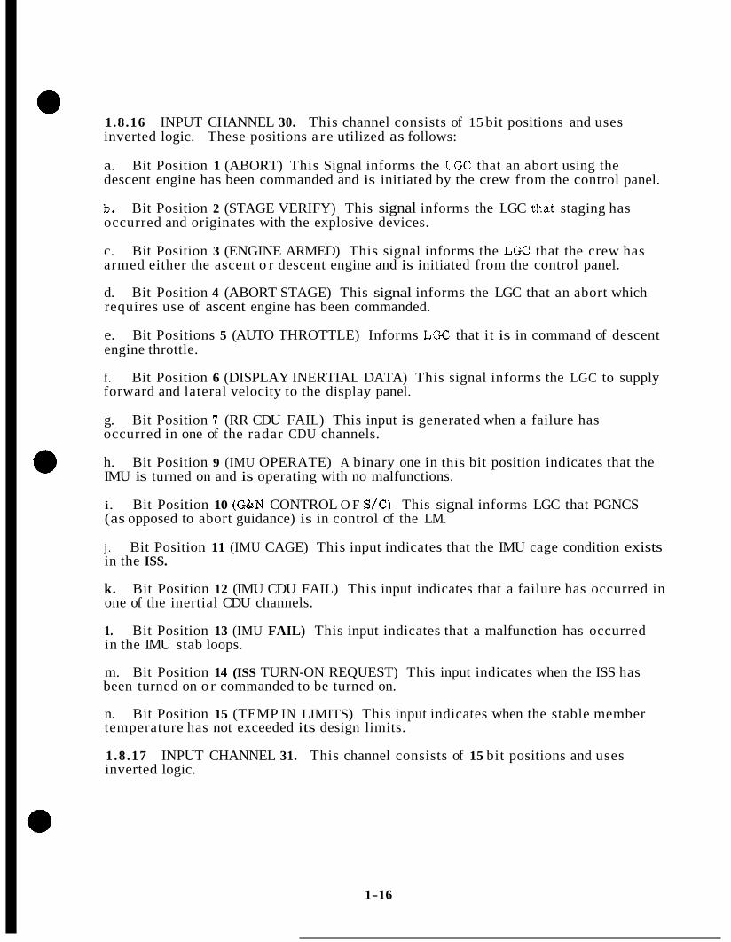
1.8.16 INPUT CHANNEL 30. This channel consists of 15 bit positions and uses inverted logic. These positions a r e utilized as follows:
a. Bit Position 1 (ABORT) This Signal informs the LGC that an abort using the descent engine has been commanded and is initiated by the crew from the control panel.
b, Bit Position 2 (STAGE VERIFY) This signal informs the LGC that staging has occurred and originates with the explosive devices.
c. Bit Position 3 (ENGINE ARMED) This signal informs the LGC that the crew has armed either the ascent o r descent engine and is initiated from the control panel.
d. Bit Position 4 (ABORT STAGE) This signal informs the LGC that an abort which requires use of ascent engine has been commanded.
e. Bit Positions 5 (AUTO THROTTLE) Informs LGC that it is in command of descent engine throttle.
f. Bit Position 6 (DISPLAY INERTIAL DATA) This signal informs the LGC to supply forward and lateral velocity to the display panel.
g. Bit Position 7 (RR CDU FAIL) This input is generated when a failure has occurred in one of the radar CDU channels.
h. Bit Position 9 (IMU OPERATE) A binary one in this bit position indicates that the IMU is turned on and is operating with no malfunctions.
i. Bit Position 10 (G&N CONTROL O F S/C) This signal informs LGC that PGNCS (as opposed to abort guidance) is in control of the LM.
j . Bit Position 11 (IMU CAGE) This input indicates that the IMU cage condition exists in the ISS.
k. Bit Position 12 (IMU CDU FAIL) This input indicates that a failure has occurred in one of the inertial CDU channels.
1. Bit Position 13 (IMU FAIL) This input indicates that a malfunction has occurred in the IMU stab loops.
m. Bit Position 14 (ISS TURN-ON REQUEST) This input indicates when the ISS has been turned on o r commanded to be turned on.
n. Bit Position 15 (TEMP IN LIMITS) This input indicates when the stable member temperature has not exceeded its design limits.
1 .8 .17 INPUT CHANNEL 31. This channel consists of 15 bit positions and uses inverted logic.
1-16

a. Bit Positions 1 and 2 (*PMI) These signals indicate *pitch manual input commands from the attitude controller. Bit positions a re utilized for landing point designator elevation changes.
b. Bit Positions 3 and 4 (*YMI) These signals indicate &yaw manual input commands from the attitude controller.
c. Bit Positions 5 and 6 (&MI) These signals indicate roll manual input commands from the attitude controller. These bit poeitions are utilized for landing point deeignator azimuth changes.
d. Bit Positions 7 through 12 ( i X , Y, Z TRANS) These signals from the translation controller command LM translation by ON/OFF firing of the RCS jets under LGC control.
e. Bit Position 13 (ATTITUDE HOLD) This signal indicates the SCS is operating in the attitude hold mode.
f. Bit Position 14 (AUTO STABILIZATION) This signal informs the LGC that the SCS is operating in the automatic mode.
g. Bit Position 15 (ATTITUDE CONTROLLER OUT O F DETENT) This signal informs the LGC that the attitude controller i s not in the neutral position.
1.8 .18 INPUT CHANNEL 32. This channel consists of 15 bit positions and uses inverted logic.
a. Bit Positions 1 through8 (THRUSTER FAIL) These eight signals inform the LGC of thruster pair shutoff so that the LGC immediately ceases to command these jets on and compensates for their loss.
b. Bit Positions 9 and 10 (PITCH OR ROLL GIMBAL OFF) This signal informs the LGC that the descent engine pitch or roll gimbal drive amplifier has been shut off by automatic failure detection circuitry.
a. Bit Position 2 (RR POWER ON/AUTO) This signal indicates that the RR power is on and the mode switch is in the automatic (computer) position.
b. Bit Position 3 (RR RANGE LOW SCALE) This signal is implemented automatically by the rendezvous radar at a range of approximately 50 nautical miles and indicates that the RR scale factor is on low scale.
c. Bit Positions 4 and 5 (RR AND LR DATA GOOD) These signals indicate that the RR and LR range trackers have locked on.
d. Bit Positions 6 and 7 (LR POSITIONS 1 AND 2) These signals indicate the position of the landing radar antenna.
1- 17

e. Bit Position 8 (LANDING VEL DATA GOOD) This signal indicates that the LR velocity trackers have locked on.
f. Bit Position 9 (LR RANGE LOW SCALE) This signal is implemented automatically by the landing radar at approximately 2500 feet range and supplied to the LG€ to indicate a change in scale factor.
g. Bit Position 10 (BLOCK UPLINK SWITCH) This signal is generated by a switch closure to inhibit reception of data via uplink. (Uplink capability not presently on LM).
h. Bit Positions 11 and 12 (UPLINK AND DOWNLINK TOO FAST) These signals a r e generated by the telemetry system indicating PGNCS telemetry rate is too high.
i. Bit Position 13 (PIPA FAIL) This signal by the computer when an accelerometer loop failure occurs.
j . Bit Position 14 (COMPUTER WARNING) This signal is generated by the computer if one of the following items occur:
1) Restart
2) Counter fail
3) Voltage fail in standby mode
4) Alarm test
5) Scaler double alarm
k. Bit Position 15 (OSC ALARM) This signal occurs if the computer oscillator stops.
1 .8 .20 OUTPUT CHANNELS 34 AND 35. These channels provide 16 bit words including a parity bit for downlink telemetry transmission.
1 . 9 COMPUTER/DSKY - HARDWARE/ASTRONAUT RELATIONSHIP
The DSKY serves an important interface function in the PGNCS. Through the DSKY the computer controls the mode of operation of the,ISS and radar, keeps the astronaut cognizant of the operational condition of certain portions of the PGNCS equipment, displays pertinent information to the astronaut and makes requests of the astronaut to perform various actions. The astronaut, in turn, is capable of loading data into the computer, requesting the display of data, commmding'system modes of operation and commanding other miscellaneous functions to be performed by the computer.
1 . 9 . 1 KEYBOARD. The keyboard consists of ten numerical keys (pushbuttons) labeled 0 through 9, two sign keys (+ o r -) and seven instruction keys: VERB, NOUN, CLR (clear), STBY (standby), KEY REL (key release), ENTR (enter) and RSET (reset), Table 1-2 lists these keys (pushbuttons) and their functions.
1- 18
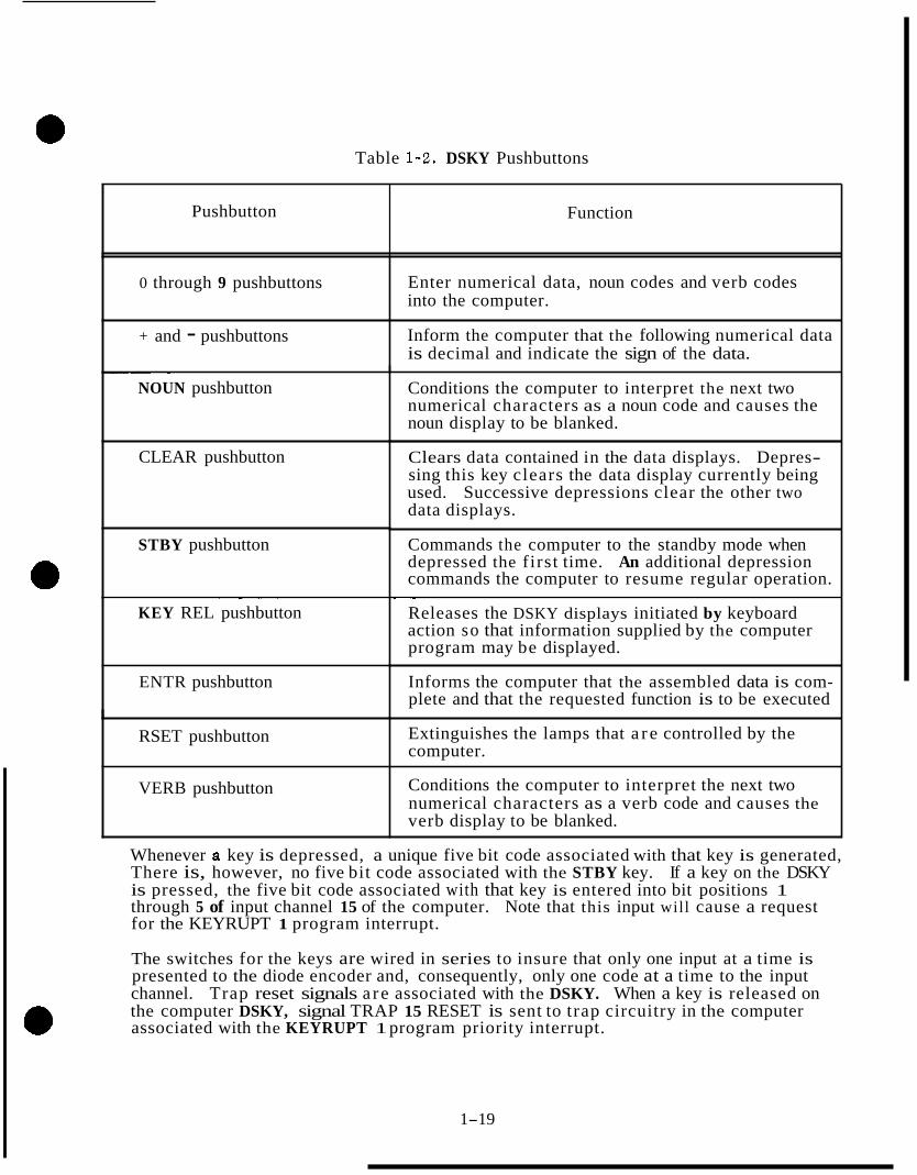
Table 1-2. DSKY Pushbuttons
Pushbutton Function
0 through 9 pushbuttons Enter numerical data, noun codes and verb codes into the computer.
+ and - pushbuttons Inform the computer that the following numerical data is decimal and indicate the sign of the data.
~ ~~ ~
NOUN pushbutton
CLEAR pushbutton
STBY pushbutton
Conditions the computer to interpret the next two numerical characters as a noun code and causes the noun display to be blanked.
Clears data contained in the data displays. Depres- sing this key clears the data display currently being used. Successive depressions clear the other two data displays.
Commands the computer to the standby mode when depressed the first time. An additional depression commands the computer to resume regular operation.
KEY REL pushbutton - ~ - ~ ~
ENTR pushbutton
~~
Releases the DSKY displays initiated by keyboard action so that information supplied by the computer program may be displayed.
Informs the computer that the assembled data is com- plete and that the requested function is to be executed
RSET pushbutton Extinguishes the lamps that a r e controlled by the computer.
VERB pushbutton Conditions the computer to interpret the next two numerical characters as a verb code and causes the verb display to be blanked.
Whenever a key is depressed, a unique five bit code associated with that key is generated, There is, however, no five bit code associated with the STBY key. If a key on the DSKY is pressed, the five bit code associated with that key is entered into bit positions 1 through 5 of input channel 15 of the computer. Note that this input will cause a request for the KEYRUPT 1 program interrupt.
The switches for the keys are wired in series to insure that only one input at a time is presented to the diode encoder and, consequently, only one code at a time to the input channel. Trap reset signals a re associated with the DSKY. When a key is released on the computer DSKY, signal TRAP 15 RESET is sent to trap circuitry in the computer associated with the KEYRUPT 1 program priority interrupt.
1-19
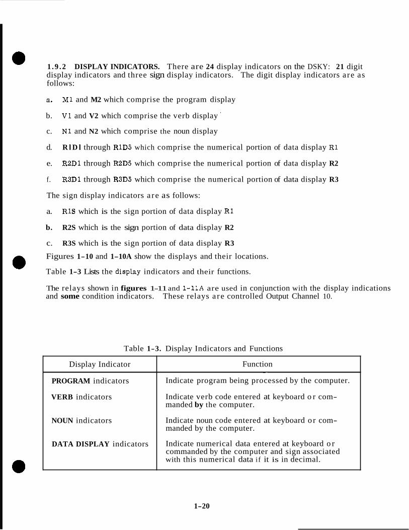
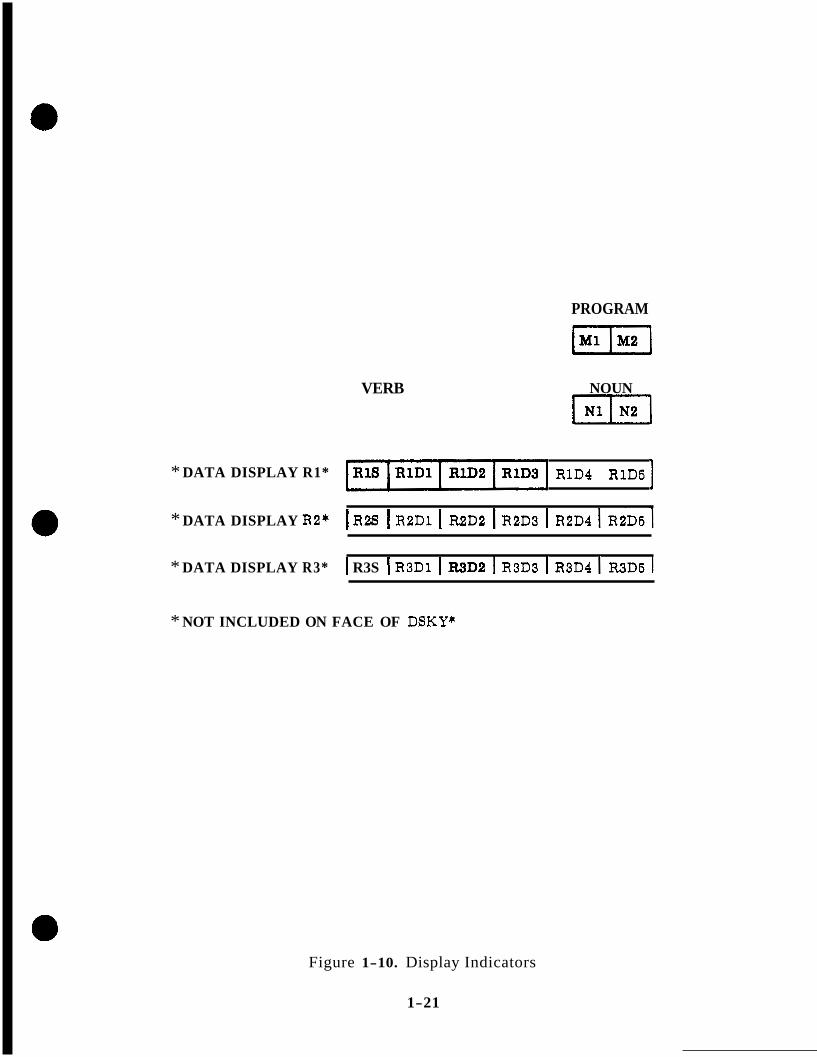
1 . 9 . 2 DISPLAY INDICATORS. There are 24 display indicators on the DSKY: 21 digit display indicators and three sign display indicators. The digit display indicators a re as follows:
a. M1 and M2 which comprise the program display
b. V1 and V2 which comprise the verb display '
c. N1 and N2 which comprise the noun display
d. R l D l through R1D5 which comprise the numerical portion of data display R1
e. R2D1 through R2D5 which comprise the numerical portion of data display R2
f. R3D1 through R3D5 which comprise the numerical portion of data display R3
The sign display indicators a re as follows:
a. R1S which is the sign portion of data display R1
b. R2S which is the sign portion of data display R2
c. R3S which is the sign portion of data display R3
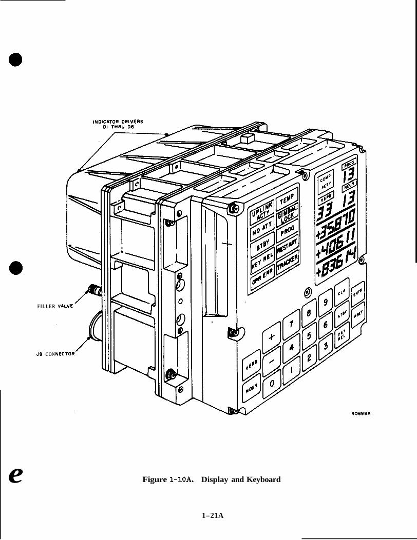
Figures 1-10 and 1-10A show the displays and their locations.
Table 1-3 Lists the disptay indicators and their functions.
The relays shown in figures 1-11 and 1-11A are used in conjunction with the display indications and some condition indicators. These relays a re controlled Output Channel 10.
Table 1-3. Display Indicators and Functions
Display Indicator
PROGRAM indicators
VERB indicators
NOUN indicators
DATA DISPLAY indicators
Function ~~ ~ -~
Indicate program being processed by the computer.
Indicate verb code entered at keyboard o r com- manded by the computer.
Indicate noun code entered at keyboard o r com- manded by the computer.
Indicate numerical data entered at keyboard o r commanded by the computer and sign associated with this numerical data if it is in decimal.
1-20
VERB
PROGRAM
( “ 2 1
-1 NOUN
* DATA DISPLAY R1* ~ 1 ~ 4 ~ 1 ~ 5
* DATA DISPLAY R2* I R2S I R2D1 I R2D2 I R2D3 I R2D4 I R2D5 1 * DATA DISPLAY R3* I R3S I R3D1 I IUD2 I R3D3 I R3D4 I R3D5 1
* NOT INCLUDED ON FACE OF DSKY*
Figure 1-10. Display Indicators
1-21
F I L L E R
J 9 CON
e
40699A
Figure 1-10A. Display and Keyboard
1-21A
1 . 9 . 3 DSKY CONDITION INDICATORS. There are fourteen condition indicators dis- played on the DSKY. Table 1-4 lists the indicators and their functions.
The UPLINK ACTY indicator will not be used on the LM DSKY.
The TEMP indicator will light if bit position 15 of input channel 30 contains a logic 0. This indicator can be lit during the atandby mode,
The GIMBAL LOCK indicator will light i f bit position 6 of output channel 10 contains a logic 1 and bit position 15 through 12 of the same channel a re 1, 1, 0 , 0 respectively.
The PROG indicator will light if bit position 9 of output channel 10 contains a logic 1 and bit position 15 through 12 of the same channel a re 1, 1, 0 , 0 respectively.
The NO ATT indicator will light if bit position 4 of output channel 10 contains a logic 1 and bit positions 15 through 12 of the same channel a re 1, 1, 0, 0 respectively.
The TRACKER indicator will light if bit position 8 of output channel 10 contains a logic 1 and bit positions 15 through 12 of the same channel a re 1, 1, 0, 0 respectively.
The STANDBY indicator will light i f the STANDBY circuit is enabled. The indicator will also light if a light test is performed.
The KEY REL indicator will light i f bit position 5 of output channel 11 is a logic 1. This indicator is modulated by the flash signal.
The OPR ERR indicator will light if bit position 7 of output channel 11 is a logic 1. This indicator is also modulated by the flash signal.
The COMP ACTY indicator will light i f bit position 2 of output channel 11 is a logic 1.
1.9 .4 DSKY OPERATION. The operator of the DSKY can communicate with the computer by the depression of a sequence of keys on the DSKY keyboard. Each depression of a key inserts a five bit code into the computer. The computer responds by returning a code to the DSKY which controls the display on a particular display panel or initiating an operation by the computer. The computer is also capable of initiating a display of information o r a request for some action to the operator through the processing of its program.
1 .9 .4 .1 Verb-Noun. The basic communication language used in the interchange of information is a pair of words known as the VERB and NOUN. Each of these words is represented by a two-digit octal code. The VERB code specifies that an action is to be performed. The NOUN code specifies on what the action is to be performed. An example of a VERB-NOUN code combination is given below.
VERB 16 -- MONITOR IN DECIMAL ALL COMPONENTS O F -- NOUN 21 -- PIPAS
1-22

12 BANKS OF I I BISTABLE RELAYS
RELAY DRIVER
DIODE DECODER
DRIVER CIRCUITS
" - "" ""
. - a - - 15 14 13 E 12
1
I I ~ l O ~ 9 ~ 8 ' i i 7 ~ 6 ~ 5 ~ 4 ~ 3 ~ 2 ~ ' 1 ~ ' IS . . 1
b 4 1 b 4
BIT 15 BIT 14 BIT 13 BIT 12 BIT l l BIT IO BIT 9 BIT 8 BIT 7 BIT 6 BIT 5 BIT 4 BIT 3 BIT 2 BIT I
n 4 BIT RELAY WORD I I RELAY BITS FROM OUTPUT CHANNEL IO CODE FROM OUTPUT CHANNEL IO
Figure 1-11. DSKY Display Relay Circuitry

R e e u h a Action I Contents of Channel 10
Program 15 14 13 1 2 \ 1 1 10 9 8 7 6 5 4 3 2 1
l2 12 I I I 1 1 0 0 0 0 0 1 0 0 0 0 0 u 0
1 1 0 0 0 0 0 0 1 0 0 0 0 0 0
12
12
12
12
12
12
Gimbal Lock Spare NO bAtt Spare Spare Spare
1 1 0 0 0 0 0 0 0 1 0 0 0 0 0
1 1 0 0 0 0 0 0 0 0 1 0 0 0 0
1 1 0 0 0 0 0 0 0 0 0 1 0 0 0
1 1 0 0 0 0 0 0 0 0 0 0 1 0 0
1 1 0 0 0 0 0 0 0 0 0 0 0 1 0
1 1 0 0 0 0 0 0 0 0 0 0 0 0 1
11 1 0 0 u 0 0 0 0 0 0 x x x x x Reg 1 Po8 5 10
0 1 1 1 0 x x x x x 0 0 0 0 0 Reg 1 Poa 4 10
0 1 1 1 1 0 0 0 0 0 u 0 0 0 0 Reg 1 ( + I
10
9 9
8
8
I
7
6
6
6
5 5 5 4
4 4 3 3
2
2
2
1 1
1
Reg 1 Po8 3
Prog. Po8 1 Prog. Po8 2 Verb Po8 2
Verb Pos 1
Noun Pos 2 Noun Pos 1
Ret3 1 (-1 Reg 1 Pos 2
Reg 1 Po8 1
Reg 2 (+) Reg 2 Po8 5 Reg 2 Fos 4
Reg 2 (-1 Reg 2 Pos 3 Reg 2 Pos 2
Reg 2 Po8 1 Reg 3 Po8 5
Reg 3 (+I Reg 3 Po8 4 Reg 3 Pos 3
Reg 3 ( 4 Reg 3 Par 2 Reg 3 Pos 1
Figure 1-1
0 1 1 1 0 0 0 0 0 0 x x x x x
1 0 1 1 0 x x x x x 0 0 0 0 0
1 0 1 1 0 0 0 0 0 0 x x x x x
1 0 1 0 0 x x x x x 0 0 0 0 0
1 0 1 0 0 0 0 0 0 0 x x x x x
1 O O 1 o x x x x x O ~ J O O O 1 0 0 1 0 0 0 0 0 0 x x x x x
0 ’ 1 1 0 1 0 0 0 0 0 0 0 0 0 0
0 1 1 0 0 x x x x x 0 0 0 0 0
0 1 1 0 0 0 0 0 0 0 x x x x x
0 1 0 1 1 0 0 0 0 0 0 0 0 0 0
0 1 0 1 0 x x x x x 0 0 0 0 0
0 1 0 1 0 0 0 0 0 0 x x x x x
0 1 0 0 1 0 0 0 0 0 0 0 0 0 0
0 1 0 0 0 x x x x x 0 0 0 0 0
0 1 0 0 0 0 ~ 0 0 0 x x x x x
0 0 1 1 0 x x x x x 0 0 0 0 0
0 0 1 1 0 0 0 0 0 0 x x x x x
0 0 1 0 1 0 0 0 0 0 0 0 0 0 0
0 0 1 0 0 x x x x x 0 0 0 0 0
0 0 1 0 0 0 0 0 0 0 x x x x x
0 0 0 1 1 0 0 0 0 0 0 0 0 0 0
o o o l o x x x x x o o o o o 0 0 0 1 0 0 0 0 0 0 x x x x x
A. DSKY Display Indications 1-22B

Indication
TEMP
GIMBAL LOCK
PROG
RESTART
TRACKER
OPR ERR
KEY REL
STBY
COMP ACTY
Table 1-4. DSKY Condition Indicators
Function
Indicates that Information is being received via uplink.
Indicates that the stable member temperature has exceeded its design limits by -+50F.
Indicates that the middle gimbal has driven through an angle greater than 70° from its zero position.
Indicates that a program check has failed. This indicator is controlled by a computer program.
Indicates :
1. That a word has been incorrectly transferred from memory - Parity fail
2. That the computer is in an endless control loop - TC Trap
3. That the computer has been interrupted for 30 milliseconds - RUPT lock.
4. That the computer has not accomplished a C S S new job within 1 .28 sec. (Night watchman)
5. That a test alarm has been generated by program control.
Indicates rendezvous radar CDU failure o r improper data from rendezvous radar.
Indicates that the Keyboard and Display program has encountered some improper operating conditions.
Indicates that the internal program has attempted to use the Keyboard and Display System and found it busy.
Indicates that the computer is in the standby condition.
Indicates to the astronaut that the ISS is not suitable for use as an attitude reference.
Indicates that the computer is in a program other than dummy job and that the computer is not in standby mode.
1-23

This combination of VERB-NOUN codes causes the accumulation of PIPA counts (as accumulated by the computer) from each of the PIPA'S to be displayed in R1 (X PIPA), R2 (Y PIPA), and R3 ( Z PIPA).
The standard procedure of inserting the VERB-NOUN codes via the keyboard is the depression of seven keys in a sequence. Using the VERB-NOUN codes previously discussed, the sequence of key depressions would be as follows:
a. VERB
b. 1
c. 6
d. NOUN
e. 2
f. 1
g . ENTER
The ENTER key depression indicates to the computer that it should perform the operation indicated by the VERB-NOUN codes.
An alternate sequence of key depressions which would accomplish the same insertion of information would be as shown beiow:
a. NOUN .
b. 2
c. 1
d. VERB
e. 1
f. 6
g. ENTER
Whenever the VERB key is depressed, the two VERB display panels a re blanked. Then as the digits of the VERB code a r e keyed in, the digits are displayed in the two VERB display panels. For example:
VERB KEY DEPRESSED -- VERB DISPLAY PANELS V1 AND V2 BLANKED
1 KEY DEPRESSED -- 1 DISPLAYED IN V I
6 KEY DEPRESSED -- 6 DISPLAYED IN V2
1- 24

Whenever the NOUN key is depressed, the two NOUN display panels, N 1 and N2, a r e blanked. As the two digits of the NOUN code a r e keyed in, the NOUN display panels display the digits of the NOUN code.
If the VERB-NOUN codes displayed in the VERB-NOUN display panels are those desired for the next entry of information, the VERB-NOUN codes need not be keyed in again. All that is required is the depression of the ENTER key. This indicates to the computer to use these codes again.
Prior to depressing the ENTER key, aRer entering the proper VERB-NOUN codes, the VERB-NOUN codes should be verified. If they are not the desired codes, the wrong action would be initiated which might cause damage to the system.
1.9.4.2 Data Loading. Some VERB-NOUN codes require more information to be keyed in other than the VERB-NOUN codes. If more data is required, after the depression of the ENTER key following the keying in of the VERB-NOUN codes, the VERB-NOUN display panels will flash on and off at a 1 . 5 cps rate. These dis- play panels will continue to flash until all of the information associated with the VERB NOUN code has been keyed in. For example, using VERB 21 (WRITE 1ST COMPONENT INTO) NOUN 16 (TIME IN SECONDS), the entry sequence would be as follows:
a. VERB
b. 2
c. 1
d. NOUN
e. 1
f. 6
g. ENTER
After the ENTER key is depressed, the VERB-NOUN display panels will flash 21 and 16, respectively. This indicates that more information is required. In this case, it is a time in seconds. Assuming that the time to be entered is +75.25 seconds, the entry procedure would be as follows:
a. +
b. 0
c. 7
d. 5
1- 25

e. 2
f. 5
g. ENTER
After the ENTER key is depressed, the VERB-NOUN display panels will stop flashing and remain on displaying VERB 21, NOUN 16. As the various keys a re depressed while inserting the data, the digits are displayed in positions of one of the display registers corresponding to the order in which they were entered. For instance, when +75.25 seconds is being entered, the + key is depressed first and + is displayed in the FUS position. The 0 key i s depressed and 0 i s displayed in RlD1. The 7 key is depressed and 7 is displayed in RlD2. This continues until the information is com- pletely keyed in. The ENTER key depression after keying the desired information not only stops the flashing of the VERB-NOUN display but indicates to the computer that it should proceed and perform the operation specified.
VERB 21 (WRITE 1ST COMPONENT INTO) 22 (WRITE 2ND COMPONENT INTO) 23 (WRITE 3RD COMPONENT INTO) 24 (WRITE 1ST AND 2ND COMPONENTS INTO) and 25 (WRITE lST, 2ND AND 3RD COMPONENTS INTO) are used to enter one, two o r three components o r portions of data into the computer. If VERB 25 (WRITE lST, 2ND AND 3RD COMPONENTS INTO) i s entered, the VERB display will illuminate and display 25. When the ENTER key is depressed after keying in the VERB-NOUN code, the VERB will display 21 (WRITE 1ST COMPONENT INTO) flashing. After the first portion of data has been keyed in, displayed in R l and the ENTER key depressed, the VERB display will illuminate 22 (WRITE 2ND COM- PONENT INTO) flashing. After the second component o r portion of the data is keyed in, displayed in R2 and the ENTER key depressed, the VERB display illuminates 23 (WRITE 3RD COMPONENT INTO) flashing. The third component of data is then entered, displayed in R3, and the ENTER key is depressed. The VERB display stops flashing and the computer proceeds to utilize the information entered.
1.9.4.3 Correcting Erroneous Data. Any time prior to depressing the last ENTER in the loading sequence, i . e. , the ENTER after the third component was inserted in the previous paragraph, erroneous information can be corrected. To correct erroneous data, the CLEAR key is used. This key causes the display register, R1, R2, and R3, last loaded to be cleared and also clears the corresponding information loaded into the computer. For example, if a three component load is being keyed in and i t i s discovered that an e r ro r exists in the first component of data in R I , after R3 has been loaded but prior to the last ENTER, the following must be done to correct the data:
DEPRESS CLEAR KEY -- R3 BLANKED -- VERB 23 DISPLAYED
DEPRESS CLEAR KEY -- R2 BLANKED -- VERB 22 DISPLAYED
DEPRESS CLEAR KEY -- R1 BLANKED -- VERB 23 DISPLAYED
RELOAD R1, R2 and R3
The CLEAR key is not used to clear the VERB, NOUN o r PROGRAM displays.
1- 26

1 .9 .4 .4 Decimal and Octal Display and Loading. Decimal and octal displays or loadings a r e distinguished by use of the + and - displays o r key inputs. Whenever decimal data is to be loaded, the + or - key must be depressed prior to keying in the digits of the data to be Loaded. If the sign keys are not used, the data is assumed to be in octal form by the computer. Whenever data i s displayed using a sign, + or - , the displayed data is in decimal. Otherwise, when the sign is not used and RlS, R2S or R3S are blanked, the data displayed is in octal.
1 . 9 . 4 . 5 Monitor vs. Display. Whenever a display type VERB is used, the requested data is transferred to the DSKY panels once each time the data is requested.
Monitoring type VERBS, in contrast, a re periodically updated and the display of the requested data changes as the requested data in the computer changes. The updating of the displayed data for a monitor type VERB is accomplished approximately every 1 second.
1 .9 .4 .6 Changing of Major Mode. The major mode refers to system operations in the various phases of a flight o r while operating on the ground. Examples of major modes are:
PRELAUNCH ALIGNMENT
GUIDANCE REFERENCE RELEASE AND BOOST
ETC.
In order to request that the system initiate one o r more major modes of operation, a different sequence of entering information through the DSKY is required. The pro- cedure would be as follows using VERB 37 (CHANGE MAJOR MODE TO).
a. VERB
b. 3
c. 7
d. ENTER
1- 27

When the ENTER key is depressed, after keying in VERB 37, the VERB display panels flash and the NOUN display panels are blanked. Now the two-digit octal code for the desired major mode can be entered through the keyboard. As the appropriate keys are depressed, the digits of the code a r e displayed in the NOUN display panels. When the ENTER key is depressed after keying in the two code digits, the major mode code is displayed in the two PROGRAM display panels M 1 and M2. If the operator wants to initiate the major mode PRELAUNCH ALIGNMENT which use the program number 01, the following keying sequence must be used:
a. VERB
b. 3
c. 7
d. ENTER
e. 0 Entry for Prelaunch Alignment mode request
f. 4 Entry indicating phase to enter Prelaunch Alignment
g. ENTER
The two program display panels would now display 0 1 and the NOUN panels would be blanked.
1.9.4.7 Mode initiation. Another group of VERBS enable the operation to initiate system mode6 of operation. Examples of these are:
COARSE ALIGN -- VERB 41
FINE ALIGN IMU -- VERB 42
ZERO -- VERB 40
Some of these VERBS do not require an associated NOUN code. For example, if the change major mode is to be initiated, the procedure would be:
a. VERB
b. 3
I c. 7
~
d. ENTER
1- 28

This would cause the system to change major mode. Other VERBS do require NOUN codes such as VERB 40 (ZERO). This VERB refers to CDU's and the NOUN code required with this VERB code specifies either the inertial o r radar CDU's (NOUN 20, inertial CDU; NOUN 40, rendezvous radar angles). If it i s desired to ZERO the inertial CDU' s , the keying procedure would be:
a. VERB
b. 4
c. 0
d. NOUN
e. 2
f. 0
g. ENTER
1 . 9 . 4 . 8 Computer Control of the DSKY. Display and monitoring of various data can be accomplished by the computer through i ts own initiative without requests for the data by the operator. The appropriate VERB-NOUN codes are displayed with the data so that it can be properly identified and used by the operator. Whenever the computer has initiated the display o r monitoring of some data, the data will be dis- played for at least 10 seconds. After th i s time duration, the computer is free to change the data displayed if it so desires.
The computer is also capable of requesting the operator to perform an action. The action that is requested is usually specified by a combination of VERB-NOUN codes and additional information displayed in one o r more of the display registers, R1, R2 and R3. For example, if VERB 50 (PLEASE PERFORM) NOUN 25 (CHECKLIST) is displayed in the VERB-NOUN display panels, R1 will display a numerically coded checklist item. When the operator has performed the requested action, the ENTER key should be depressed. This indicates to the computer that the operation has been completed. If the operator does not wish to perform the action requested, he may use VERB 33 (PROCEED WITHOUT DATA) o r VERB 34 (TERMINATE). These VERB codes indicate to the computer to continue on without the data o r requested action as best it can o r to terminate the function it is performing.
1.9 .4 .9 DSKY/Computer/Operator Interlocks. While the operator of the DSKY is using: the DSKY to load, display, etc. , the computer cannot interrupt this process. An Gterlock is set up by the computer inhibiting itself from using the DSKY. Therefore, the DSKY operator should remove this interlock when he is finished using it. This is accomplished by depressing the KEY RELEASE key, This action removes the DSKY-OPERATOR interlock and enables the computer to use the DSKY.
- "
The computer is capable of requesting that the DSKY operator release the DSKY so the computer may use it. Illuminating the KEYRLSE panel on the DSKY FAILURE INDICATOR PANEL indicates that the computer has some data to display to the operator. The operator is not obligated to release control of the DSKY if he wishes to continue to use it.
1-29

As previously mentioned, when the computer has initiated a display of data, the data will be displayed for at least 10 seconds before the computer is able to display different data. This is because of an interlock the computer imposes on itself to enable the operatdr time enough to read the data displayed. After 10 seconds have elapsed, the computer drops the interlock and is free to display different data to the operator.
1.9.5 VERB-NOUN LIST. Contained in this section of the study guide is a complete listing of the VERB and NOUN codes which a re used with the Sunburst Rev. 14 computer pro- gram. A brief description is also given for each of the VERB and NOUN codes along with the scaling of the data converted and displayed on the DSKY as a result of NOUN code usage. Keep in mind that many combinations of these codes exist; however, some of the combinations are non-sensical o r illegal. Some VERB codes do not require a NOUN code to completely specify the desired action.
1.9.5.1 Verb Codes. The VERB codes a r e divided into two groups - Ordinary an Extended. The ordinary verbs generally a r e involved in the manipulation (loading display, etc.) of data. The extended verbs, in general, a re used for initiation of actions (moding requests, equipment operation, etc. ).
ORDINARY VERBS
Verb Code
00
01
02
03
04
05
06
07
10
11
12
13
Function
Illegal
Display (in octal) 1st component of:
Display (in octal) 2nd component of:
Display (in octal) 3rd component of:
Display (in octal) 1st and 2nd components of:
Display (in octal) lst, 2nd and 3rd components of:
Display (in decimal) all component's of:
Double Precision decimal display
Spare
Monitor (in octal) 1st component of:
Monitor (in octal) 2nd component of:
Monitor (in octal) 3rd component of:
Display Location
R1
R1
R1
R1, R2
R1, R2, R3
A s appropriate
R1, R2
R1
R1
R1
1-30
Verb Code
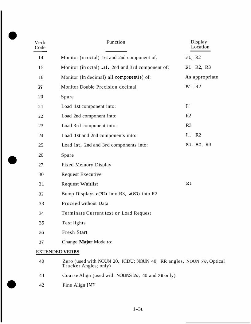
14
15
16
17
20
21
22
23
24
25
26
27
30
31
32
33
34
35
36
37
- Function
Monitor (in octal) 1st and 2nd component of:
Monitor (in octal) lst, 2nd and 3rd component of:
Monitor (in decimal) all component(s) of:
Monitor Double Precision decimal
Spare
Load 1st component into:
Load 2nd component into:
Load 3rd component into:
Load 1st and 2nd components into:
Load lst, 2nd and 3rd components into:
Spare
Fixed Memory Display
Request Executive
Request Waitlist
Bump Displays c(R2) into R3, c(R1) into R2
Proceed without Data
Terminate Current test o r Load Request
Test lights
Fresh Start
Change Major Mode to:
Display Location
R1, R2
R1, R2, R3
A s appropriate
R1, R2
R1
R2
R3
R1, R2
R1, R2, R3
R1
EXTENDED VERBS
40 Zero (used with NOUN 20, ICDU; NOUN 40, RR angles, NOUN 7 0 ; Optical Tracker Angles; only)
41 Coarse Align (used with NOUNS 20, 40 and 7 0 only)
42 Fine Align IMU
1-3 1
"
~
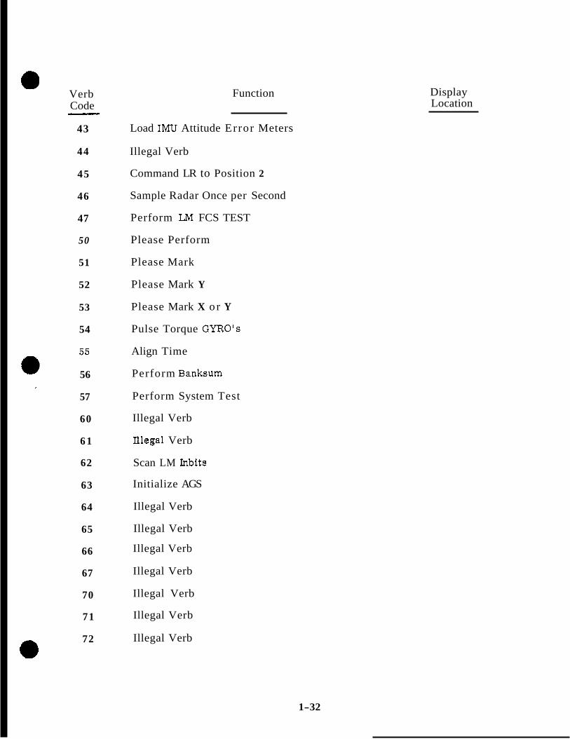
Verb Code
43
44
45
46
47
50
51
52
53
54
55
56
57
60
6 1
62
63
64
65
66
67
70
71
72
- Function
Load IMU Attitude Error Meters
Illegal Verb
Command LR to Position 2
Sample Radar Once per Second
Perform LM FCS TEST
Please Perform
Please Mark
Please Mark Y
Please Mark X or Y
Pulse Torque GYRO'S
Align Time
Perform Banksum
Perform System Test
Illegal Verb
Illegal Verb
Scan LM Inbits
Initialize AGS
Illegal Verb
Illegal Verb
Illegal Verb
Illegal Verb
Illegal Verb
Illegal Verb
Illegal Verb
Display Location
1-32

Verb Code
Function
73 RHC Used For Minimum Impulse
74 RHC Used For Rate Command
*7 5 DAP Wide Deadband
*7 6 DAP Narrow Deadband
77 Illegal Verb
1. 9 . 5 . 2 Verb Descriptions.
ORDINARY VERBS
Verbs 01 - 05 Perform octal displays of data.
Verb 06
Verb 07
Verbs 11 - 17
Verbs 21 - 25
Verb 27
Performs decimal display of data, The scale factors, types of scale factor routines, and component information a r e stored within the computer for each Noun which is required to display in decimal.
Performs a double precision decimal display of data. It does no scale factoring. It merely performs a 10 character fractional decimal conversion of two consecutive erasable registers using R1 and R2 (the sign is placed in the R 1 sign position; the R2 sign position is blank). It cannot be used with Mixed Nouns. Its intended use is primarily with "Machine Address to be Specified" Nouns. If this verb is used with nouns that are inherently not double precision, the display will be meaningless.
The monitor verbs allow other keyboard activity. It is ended by terminate, VERB 34, any noun-verb subroutine that passes the DSKY block o r another monitor. Monitor action is suspended but not ended, by any keyboard action except e r r o r reset and begins again when the KEY RELEASE is initiated.
Perform data load. Octal quantities are unsigned. Decimal quantities are preceded by a + o r - sign.
Bank Display. This Verb is included to permit displaying the contents of fixed memory in any bank. Its intended use is for checking program ropes and the BANK position of program ropes.
* Not included in Sunburst Rev 14 Listing
1-33

. .
ORDINARY VERBS (Cont'd)
Verb 30
Verb 31
Verb 32
Verb 33
Verb 34
Verb 35
Enters request to Executive Routine for any machine address with priority. This Verb i s used with the Noun "Machine Address to be Specifiedtf. This Verb assumes that Noun 26 has been preloaded with
Component 1 Priority (bits 10-14), bit 1 = 0 for NOVAC and 1 for FINDVAC.
Component 2 Job address (12 bits)
Component 3 Both Bank Constants.
The End of Job subroutine is performed after the request is entered. The display system is also released.
Enters request to Waitlist Routine for any machine address with any delay. This Verb is used with the "Machine Address to be Specified" Noun. This Verb assumes that Noun 26 has been preloaded with
Component 1 Delay (the desired number of 10 millisecond units of delay in the low bits)
Component 2 Task Address (12 bits)
Component 3 Both Bank Constants
The End of Job subroutine is performed after the request is entered. The Display system is also released.
Display Shift. Useful for preserving an existing display of a quantity while displaying another quantity.
Proceed without Data. Informs routine requesting data to be loaded that the operator chooses not to load fresh data, but wishes the routine to continue as best it can with old data. Final decision for what action should be taken is left to requesting routine.
Terminate. Informs routine requesting data to be loaded that the operator chooses not to load fresh data, and wishes the routine to terminate. Final decision for what action should be taken is left to requesting routine. If Monitor is one, it is turned off.
The Test Lamps routine checks all of the DSKY lamps. After 5 seconds, the caution and status lamps are returned to their original setting.
1-34

ORDINARY VE RBS (cont' d) ,
Verb 36
Verb 37
EXTENDED VERBS
Verb 40
Verb 41
Verb 42-43
Verb 45-46
Verb 47
Verb 50
Verbs 51-53
Verb 54
Verb 55
Verb 56
Initializes the program control software and Keyboard and Display System Program.
This verb changes the major mode. This is accomplished by inserting VERB 37 ENTER, MAJOR MODE, ENTER. The new major mode number is in the noun display until ENTER is push. At this time the new major mode number will be in the Program display.
Must be used with Noun 20 (ICDU), Noun 40 (RR Angles) o r Noun 70 (Optical Tracker Angle) only.
Must be used with Noun 20, Noun 40 o r Noun 70 only.
Call programs that perform the indicated PGNCS procedure.
Call programs to perform the indicated radar procedure.
Call program to perform the digital autopilot test.
This verb is used only by internal routines that wish the operator to perform a certain task. It should never be keyed in by the operator. It is usually used with Noun 25 (Checklist). The coded number for the Checklist Item to be performed is displayed in register R1 by the requesting routine.
Once the operator has performed the requested action, he should press ENTER to indicate that the Checklist Item has been performed. If he wishes not to perform the requested action, he should key in the Verb "Proceed Without Data".
Verbs 51, 52 and 53 a r e used only by internal routines that wish the operator to MARK. They should never be keyed in by the operator. It is usually used with Noun 30 (Star Numbers). The numbers of the stars to be marked are displayed in registers R1, R2, R3 by the requesting routine. He should never press ENTER with Verbs 51, 52 o r 53. .
Call program that performs the indicated PGNCS procedure.
Used to update the computer clock.
Check the sum of the fixed memory bank as a cursory check of the validity of the memory.
1-35
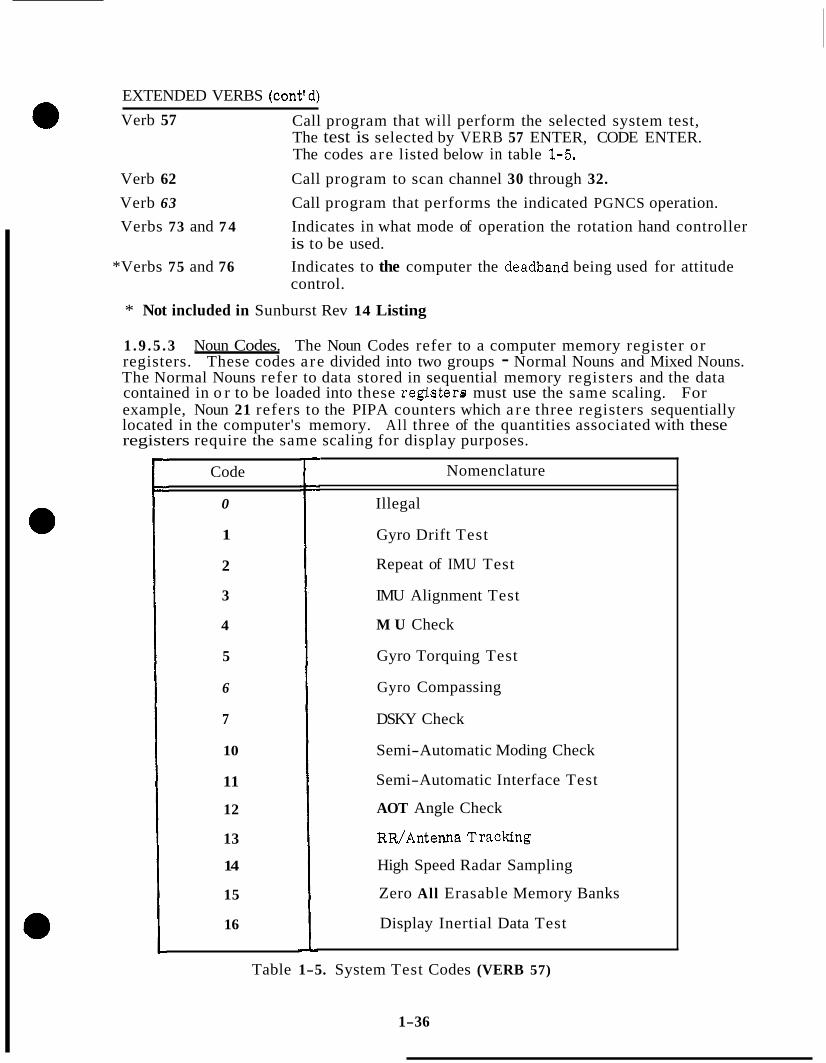
EXTENDED VERBS (cont'd) Verb 57 Call program that will perform the selected system test,
The test is selected by VERB 57 ENTER, CODE ENTER. The codes are listed below in table 1-5.
Verb 62 Call program to scan channel 30 through 32. Verb 63 Call program that performs the indicated PGNCS operation. Verbs 73 and 7 4 Indicates in what mode of operation the rotation hand controller
is to be used. *Verbs 75 and 76 Indicates to the computer the deadband being used for attitude
control.
* Not included in Sunburst Rev 14 Listing
1 .9 .5 .3 Noun Codes. The Noun Codes refer to a computer memory register or registers. These codes a re divided into two groups - Normal Nouns and Mixed Nouns. The Normal Nouns refer to data stored in sequential memory registers and the data contained in o r to be loaded into these registerra must use the same scaling. For example, Noun 21 refers to the PIPA counters which a r e three registers sequentially located in the computer's memory. All three of the quantities associated with these registers require the same scaling for display purposes.
Code
0
1
2
3
4
5
6
7
10
11
12
13
14
15
16
Nomenclature
Illegal
Gyro Drift Test
Repeat of IMU Test
IMU Alignment Test
M U Check
Gyro Torquing Test
Gyro Compassing
DSKY Check
Semi-Automatic Moding Check
Semi-Automatic Interface Test
AOT Angle Check
RR/Antenna Tracking
High Speed Radar Sampling
Zero All Erasable Memory Banks
Display Inertial Data Test
Table 1-5. System Test Codes (VERB 57)
1-36

The other type of noun code, the Mixed Noun, refers to data which is not necessarily located in sequential memory registers nor necessarily use the same scaling. For example, Noun 60 when used with a display verb causes the display of the contents of the landing radar velocity Z and the computer's real time reference. These two quantities are not stored in sequential memory registers nor do they require the same scaling or conversion techniques for their display.
NORMAL NOUNS
Noun Code
00
01
02
03
04
05
06
07
10
11
12
13
14
15
16
17
20
21
22
23
24
Function
Not in use.
Specify Machine Address (. X x x X X )
Specify Machine Address (XxXxx. )
Specify Machine Address (XXX. XX Degrees)
Specify Machine Address (XXX. XX Hours)
Specify Machine Address (XXX. XX Seconds)
Specify Machine Address (XX.XXX Gyro Degrees)
Spare
Channel to be specified
Spare
Spare
Spare
Spare
Increment Machine Address (octal only)
Time (XXX.XX seconds)
Time (XXX.XX Hours)
ICDU (XXX.XX Degrees)
PIPA's (xXXXX. Pulses)
New Angles I (XXX. XX Degrees)
Delta Angles I (XXX.XX Degrees)
Delta Time (XXX. XX Seconds)
1-37

NORMAL NOUNS (Cont'd. )
Noun Code Function
25 Checklist (XXXXX. )
26
27
30
31
32
33
34
Prio/Delay, Address, BBCON (Octal Only)
Self Test On/Off Switch ( x X X X X . )
Star Numbers (XXXXX. )
Failreg, SFAIL, ERCOUNT [Rl, R2, R3 (octal onlyfl
Midcourse Decision Time [XXX.XX Hours (Internal Units = Weeks)]
Midcourse Ephemeris Time [?CXX.XX Hours (Internal Units = Weeks)]
Midcourse Measured Quantity (XXXX. X Kilometers)
35 Inbit Message (Octal Only)
36 Landmark Data 1 (Octal Only)
37 Landmark Data '2 (Octal Only)
40
41
RR Trunnion and Shaft Angles (XXX. XX Degrees)
New RR Trunnion and Shaft Angles (XXX. XX Degrees)
42 AOT Rotation Angles (xruC.XX Degrees)
43
44
45
AOT Detent Code (XXXXX.)
Forward Velocity Lateral Velocity (XXXXX. feet/second)
Rotational Hand Controller Angle Rates (xXXXX. Degreedsecond)
46 Spare
47 Spare
50 Spare
51 Spare
1-38

NORMAL NOUNS (Cont'd.)
Noun Code Function
52 Gyro Bias Drift (. BBXXXM( millirad/second)
53
54
Gyro Input Axis Acceleration Drift (. BBXXXXX mil l i radsec) cm/sec2
Gyro Spin Axis Acceleration Drift (. BBXXXXX millirad/sec) cm/sec2
55 LR Altitude, Time (XXXXX. Feet, XXX. XX sec)
56 LR Vx, Time ( X x x x x . Feet/Sec. XXX. XX Seconds)
57 LR Vy, Time ( X x x X X . Feet/Sec., XxX.XX Seconds)
60 LR V z , Time (X-. Feet/Sec. , XXX. XX Seconds)
61
62
63
64
Target Azimuth and Elevation (XXX. XX Degrees, XX. XXX Deg* )
RR Range, Shaft, Trunnion (XXXXXB. Feet, XXX.XX Degrees, XXX. XX Degrees) RR Range Rate, Shaft, Trunnion (Xlouoc. Feet, XXX.XX Deg. , XXX.XX Deg.)
Initial Altitude, Final Altitude, Altitude Rate (XxxXX. Feet, -. Feet, XxxXx. Feet/Second)
65 Sampled Time (XXX.XX Hours, XXX. XX Seconds)
66 System Test Results ( X x x x x . , .xXXXX, XXXXX. )
67 Delta GYRO Angles (XX.xxX Degrees for Each)
70
7 1
Optical Tracker Azimuth and Elevation Angles (xxlx.XX Degree, XXX. XX Degree)
Desired Optical Tracker Azimuth and Elevation Angles (XXX. XX Degrees, XXX. XX Degrees)
72 Delta Position (XXXX. X Kilometers for Each)
73 Delta Velocity (XXXX. X MeterdSecond for Each)
74 Midcourse Measurement Data (XXX. XX Hours, XXXX. X Kilometers, xXXXX. )
1-39

NORMAL NOUNS (Cont'd. )
Noun Code Function
75 Midcourse Measurement Deviations (XXXX. X Kilometers, XXXX. X Meterdsecond, XXXX. X Kilometers)
76 Position Vector (XXXX.X Kilometers for Each)
77 Velocity Vector (xxm, X MeterdSecond for Each)
1.10 INTERRELATIONSHIP OF PROCESSING FUNCTIONS
The interrelationship of processing functions in the computer becomes quite involved especially when all of the possible combinations of the processing functions are considered. The processing of counter interrupt inputs enabling the accumulation of incremental data is performed as required. The processing of program interrupts occurs as required handling the major portion of the input and output functions for other programs and routines, and timing the execution of various tasks. The processing of program controlled pro- cessing functions is carried on with the priority of the processing routine determining when a particular job is to be processed. The scheduling, terminating, changing, etc. of jobs and tasks is continuously being performed. Considerable interchange of data between various jobs and tasks is continuously in process.
At this point in the study guide, an example is given showing the interrelationships of some of these processing functions. The example used is the complter controlled IMU ZERO mode switching routine. In this example, it is assumed that the request to perform the mode switching routine is made through DSKY entries, although it is used by other mission programs and forms a part of these programs.
In order to request the IMU ZERO mode switching routine to be performed, the astronaut enters through the DSKY keyboard this sequence of key depressions:
a. VERB
b. 4
c. 0
d. NOUN
e . 2
f . 0
g. ENTER
1-40

This sequence of entries indicates to the computer that is should zero the inertial CDU channels, VERB 40 ~tates that something should be zeroed while NOUN 20 specifies the inertial CDU channels.
As each of the keys are depressed for the VERB-NOUN codes, the control of the computer hardware ie forced to the KEYRUPT routine. (%e figure 1-12. ) The KEYRUPT routine processes the keycode input and u8es the Executive routine to schedule the PINBALL pro- gram to be processed on a program priority basis. After the scheduling is completed, the Executive routine returns control to the KEYRUPT routine which returns control back to the processing function Interrupted by the KEYRUPT.
Within 20 m. 8. of the time the Pinball program was scheduled, the processing of one of the routines of PINBALL is initiated under Executive control, if PINBALL has the highest priority of the scheduled jobs. PINBALL processee the input keycodes and furnishes the T4RUPT routine with the data required for display of the keycode inputs. The T4RUPT routine drives the DSKY displays with this information. The DOWNRUPT routine pro- vides the same Information for transmission by the DOWNLINK telemetry system. After PINBALL has completed the processing of each keycode input, the PINBALL job is terminated and control is returned to the next lower priority scheduled job under executive control.
Finally, when the ENTER key is depressed, the KEYRUPT routine is again initiated which again schedules the PINBALL program through the Executive routine and returns control to the processing function which was interrupted. Again, within 20 m. s. , PINBALL program processing is initiated if it is the highest priority scheduled job. With the ENTER keycode input, the PINBALL routine uses the assembled VERB and NOUN codes to transfer control via BANKCALL to the IMU ZERO mode switching routine. This routine is executed under control of the scheduled PINBALL routine which is, in turn, executed under control of the Executive routines.
The IMU ZERO mode switching routine checks to determine if the IMU is being caged. If the IMU CAGE signal is present, IMU ZERO is terminated, through Executive action. If the IMU CAGE signal is not present, the inertial CDU and IMU fail indications are inhibited. A command i s issued to zero the inertial CDU channele. After the inertial CDU ChaMeh are commanded to zero, the IMU ZERO2 task is scheduled on the WAITLIST to be executed in 320 milliseconds. After scheduling the IMU ZERO2 a check is made to insure that the IMU i s operating, The IMU ZERO job is now terminated through Executive action. The 320 millisecond time delay in the execution of this moding operation allows sufficient time for the inertial CDU channels to zero.
After 320 milliseconds have elapsed from the time that IMU ZERO2 task was scheduled on the WAITLIST, the T3RUPT routine will result as a function of overflow. The TIME 3 counter and the IMU ZERO2 task will be executed. If the IMU CAGE signal is present, IMU ZERO2 i s terminated through TSRUPT and the interrupted job will be resumed. If the IMU CAGE signal is not present, the computer's inertial CDU counters are ret to zero and the inertial CDU zero command is removed. A four second delay is now scheduled on the WAITLIST. At the end of this delay, the task IMU ZERO3 is performed. After IMU ZERO3 is scheduled on the WAITLIST, processlng control is returned to the interrupted job through the TSRUPT routine. This ends the IMUZERO routine.
1-4 1
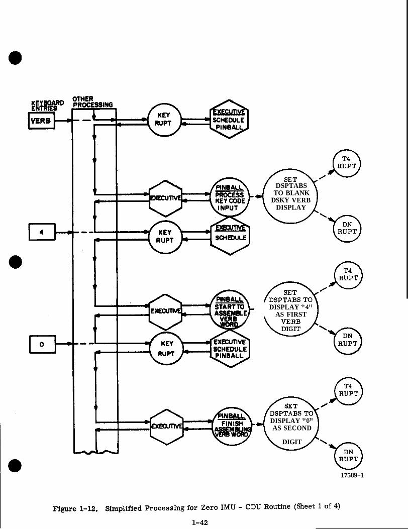
THLR 'ROCESSING
t I DSPTABS
TO BLANK DSKY VERB
DISPLAY
0
' \
AS FIRST DISPLAY "4"
DISPLAY tlO" ' AS SECOND
DIGIT @ 17589-1

17589-2
Figure 1-12. Simplified Processing for Zero N U - CDU Routine (Sheet 2 of 4)
1-43

I
EXEC UTIVE SCHEDULE PINBALL
EXECUTIVE INITIATE 188 CDU ZERO MODE
A BANKCALL
SET UP ADDRESS OF
IMU ZERO FOR PROCESSING
IMU ZERO
THE IMU BEING CAGED? IF SO, END IMU ZERO t I EXECUTIVE 4 CAGED
INHIBIT INERTIAL CDU & IMU FAIL INDICATIONS
t-“
17589-3
Figure 1-12. Simplified Processing for Zero IMU - CDU Routine (Sheet 3 of 4)
1-44

320 T MILLfaEC c
i 4 SEC.
r
c r r
n WAITLIST 4-
4 T3RUPl'
LA IMU ZERO 2
18 THE IMU BEING CAGED? IF SO, END IMU ZERO 2
BET COMPUTERtH 188 CDU COUNTERS TO ZERO I
REMOVE IS8 CDU ZERO COMMAND
SCHEDULE 4 SECOND DELAY FI)R I89 CDU .COUNTERS TO SYN- CHRONIZE WITH. THE IMU GIMBALS (SCHED- ULE " M U ZERO 3"
IMU ZERO 3
T3RUPI' I8 THE IMU BEING CAGED? IF 90 , END IMU ZERO 3
REMOVE INERTIAL CDU & KMU FAIL INHIBITS
JOB
T3RUPT 4 I IS THE USING JOB NOT ASLEEP ABLEEP? IF NOT,
TERMINATE TASK I
L
17589-4

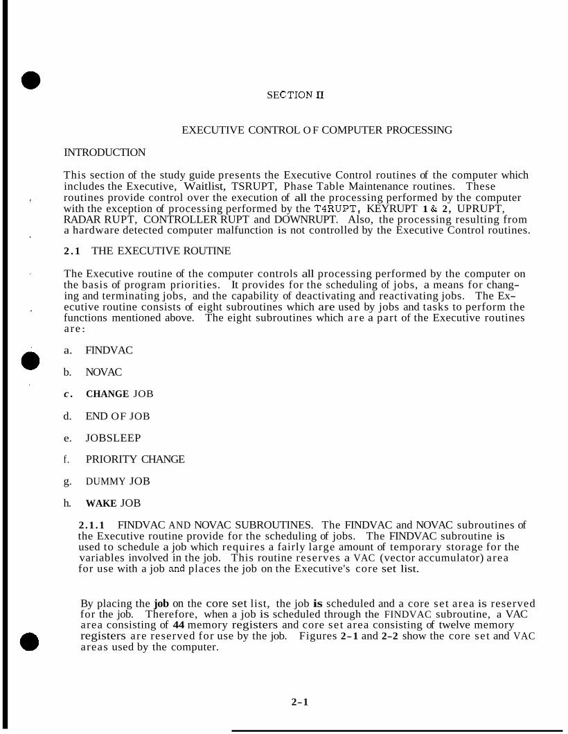
SE C TION 11.
EXECUTIVE CONTROL O F COMPUTER PROCESSING
INTRODUCTION
This section of the study guide presents the Executive Control routines of the computer which includes the Executive, Waitlist, TSRUPT, Phase Table Maintenance routines. These routines provide control over the execution of all the processing performed by the computer with the exception of processing performed by the T4RUPT, KEYRUPT 1 & 2 , UPRUPT, RADAR RUPT, CONTROLLER RUPT and DOWNRUPT. Also, the processing resulting from a hardware detected computer malfunction is not controlled by the Executive Control routines.
2 . 1 THE EXECUTIVE ROUTINE
The Executive routine of the computer controls all processing performed by the computer on the basis of program priorities. It provides for the scheduling of jobs, a means for chang- ing and terminating jobs, and the capability of deactivating and reactivating jobs. The Ex- ecutive routine consists of eight subroutines which are used by jobs and tasks to perform the functions mentioned above. The eight subroutines which a re a part of the Executive routines a re :
a. FINDVAC
b. NOVAC
c . CHANGE JOB
d. END OF JOB
e. JOBSLEEP
f. PRIORITY CHANGE
g. DUMMY JOB
h. WAKE JOB
2.1 .1 FINDVAC AND NOVAC SUBROUTINES. The FINDVAC and NOVAC subroutines of the Executive routine provide for the scheduling of jobs. The FINDVAC subroutine is used to schedule a job which requires a fairly large amount of temporary storage for the variables involved in the job. This routine reserves a VAC (vector accumulator) area for use with a job and places the job on the Executive's core set list.
By placing the job on the core set list, the job is scheduled and a core set area is reserved for the job. Therefore, when a job is scheduled through the FINDVAC subroutine, a VAC area consisting of 44 memory registers and core set area consisting of twelve memory registers are reserved for use by the job. Figures 2-1 and 2-2 show the core set and VAC areas used by the computer.
2-1

Core Set Area #O
Core Set Area #1
Core Set Area #2
Core Set Area #3
Core Set Area #4
Core Set Area #5
Core Set Area #6
Memory Address
140
146
147
150
151
152
153
+
154
167
17 0
203
2 04
217
220
233
234
247
250
26 3
+
4
+
+ 4
+
Use
MPAC (Multi-Purpose Accumulator)
MODE (+1 for TP, + O for DP, o r -1 for Vectors)
LOC (Location Associated with Job)
BANKSET (Usually contains BBANK Setting)
PUSHLOC (Word of Packed Interpretive Parameters)
PRIORITY (Priority of Present Job and VAC Area Address, if required)
(See Note)
(See Note)
(See Note)
(See Note)
(See Note)
(See Note)
NOTE: The 12 memory locations in each core set area are used a s those i n Core Set Area # 0 shown above.
Figure 2-1. Executive's Core Set List
2 -2
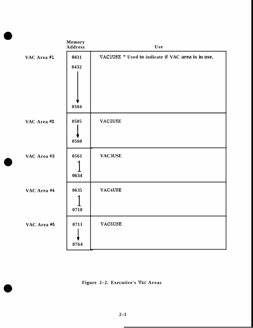
Memory Address Use
VAC Area #1
VAC Area #2
e VAC Area #3
VAC Area 84
VAC Area #5
04 31
0432
0504
0505
0560
0561
1 0634
06 35
1 0710
0711
07 64
~~~~ ~ ~ ~~ ~ ~~ ~~
VAClUSE - Used to indicate if VAC area is in use.
VAC2USE
VAC 3USE
VAC4USE
VAC5USE
Figure 2-2. Executive's Vac Areas
2 -3

Whenever a job doesn't require a large amount of storage capacity and its requirements a re satisfied by the storage provided by the core set area, the NOVAC subroutine is used to schedule the job. This subroutine places the job on the core set list, thereby schedul- ing the job and reserving a core set area for use by the job.
In order for a job to be scheduled, the job o r task desiring to schedule the job supplies either of these two subroutines, FINDVAC o r NOVAC, with the priority number and the starting address of the job to be scheduled. The job o r task scheduling the job loads the Accumulator register of the computer with the priority number of the job prior to trans- ferring control to the Executive's FINDVAC or NOVAC routines, The two memory reg- isters immediately following the instruction which transfers control to either of these routines of the Executive, contains the complete starting address of the job.
The first thing done by either of these routines, as shown by the flow chart in Figure 2-3, is to temporarily store the priority number contained in the Accumulator register. Next the routine temporarily stores the complete address of the job being scheduled which is contained in the two memory registers following the transfer of control instruction which routed control to either FINDVAC o r NOVAC. The complete address of the exit point of the scheduling routine is temporarily stored so control can be returned to the job o r task at this point after completing the scheduling.
If the NOVAC subroutine is being used, the core set areas are scanned to find one which is not in use. This is accomplished by ftlooking7f at the contents of the priority register in each of the core set areas. The priority register contains the priority number of the job for which the core set area is reserved if it is reserved. If the core set is not reserved for a job, the priority register will contain a - 0 .
If an unreserved core set area is not found, the Program Caution indicator is lighted. Also, the information for the display of VERB 05, NOUN 31 and 01202 in R 1 is provlded to the T4RUPT routine. This Verb, Noun and failure number display means: (VERB 05) Display octal component 1, 2, 3 of (NOUN 31) FAIL REGISTER and (01202 in R1) EXECUTIVE OVER- FLOW - NO CORE SETS AVAILABLE. A f t e r this is done, a TC TRAP condition is forced which causes the processing of the RESTART routine.
If the FINDVAC subroutine is being used, after storing the priority number, starting ad- dress and return address, the five VAC areas are scanned to find one which is available. When one is found available, it is reserved for the job and the address of the VAC area is stored. Then, the core set list is scanned to find an available core set work area as was previously discussed for the NOVAC subroutine. The remainder of the FINDVAC sub- routine is identical to that of NOVAC except that the address of the reserved VAC area is also stored in the core set area.
If a VAC area is not found available when the VAC areas a re scanned, the Program Caution indicator is illuminated. Also, the information for the display of VERB 05, NOUN 31 and 01201 in R1 is provided to the T4RUPT routine. The display in R1 of the DSKY (01201) means EXECUTIVE OVERFLOW - NO VAC AREAS AVAILABLE. After this is done, a TC TRAP condition is forced which causes the processing of the RESTART routine,
2-4

READ L m o R E PRIDRmY L ADDREBB OF JOB TO BE WXCDULCDFROM IICHEPUWO PROQMM
READ h STORE PRIORCI'Y (I ADDREBB OF JOB TO BE SCHEDULED FROM SCHEDULMG PROGRAM
I
4
4
+ SAVE COMPUTE SAVE COMPLETE ADDRESS OF Em POWT OF SCHEDUWO PROORAM
ADDREBB OF EXTI' POI" OF SCHEDULING PROGRAM
SCAN VAC AREAS TO
NOT M USE FIND ONE WHICH m b
w SCAN CORE SET LLBT TO FIND A CORE SET AREA NOT m USE
ADDRESS OF RESERVED
RESERVE CORE SET
.WORE AIIIIHELII O F VAC AREA IF ONE (8
4
ADDREBE OF JOB
SET AREA IN RESERVED CORE
FURCE.TC TRAP
Figure 2-3. Executive's Findvac and Novac
2-5
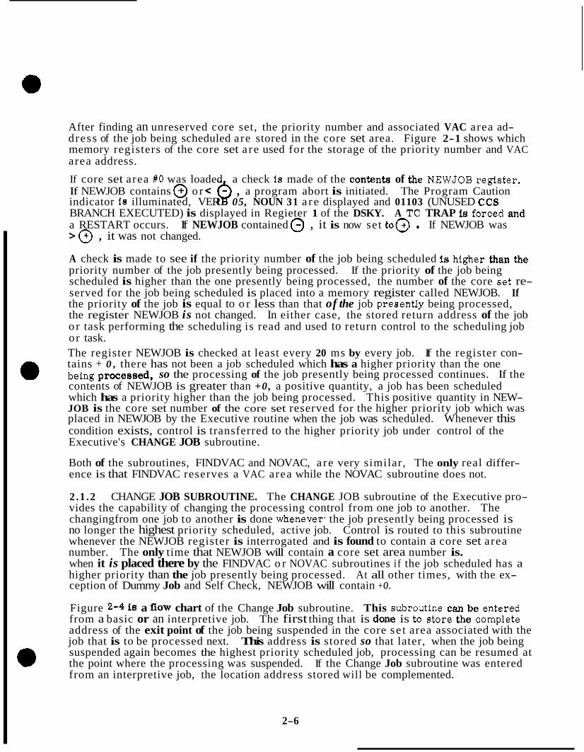
After finding an unreserved core set, the priority number and associated VAC area ad- dress of the job being scheduled are stored in the core set area. Figure 2-1 shows which memory registers of the core set a re used for the storage of the priority number and VAC area address.
If core set area #O was loaded a check ie made of the contents of the NEWJOB register. If NEWJOB contains @ or x , a program abort is initiated. The Program Caution indicator ie illuminated, VER Q 05, NOUN 31 a re displayed and 01103 (UNUSED CCS BRANCH EXECUTED) is displayed in Regieter 1 of the DSKY. A TC TRAP is forced and a RESTART occurs. If NEWJOB contained 0 , it is now set to@ . If NEWJOB was > @ , it was not changed.
A check is made to see if the priority number of the job being scheduled is higher than the priority number of the job presently being processed. If the priority of the job being scheduled is higher than the one presently being processed, the number of the core set re- served for the job being scheduled is placed into a memory register called NEWJOB. If the priority of the job is equal to o r less than that of the job preeently being processed, the register NEWJOB is not changed. In either case, the stored return address of the job o r task performing the scheduling is read and used to return control to the scheduling job or task. The register NEWJOB is checked at least every 20 ms by every job. If the register con- tains + 0 , there has not been a job scheduled which has a higher priority than the one being prOCes8ed, so the processing of the job presently being processed continues. If the contents of NEWJOB is greater than +0, a positive quantity, a job has been scheduled which has a priority higher than the job being processed. This positive quantity in NEW- JOB is the core set number of the core set reserved for the higher priority job which was placed in NEWJOB by the Executive routine when the job was scheduled. Whenever this condition exists, control is transferred to the higher priority job under control of the Executive's CHANGE JOB subroutine.
Both of the subroutines, FINDVAC and NOVAC, a re very similar, The only real differ- ence is that FINDVAC reserves a VAC area while the NOVAC subroutine does not.
2 .1 .2 CHANGE JOB SUBROUTINE. The CHANGE JOB subroutine of the Executive pro- vides the capability of changing the processing control from one job to another. The changingfrom one job to another is done whenever, the job presently being processed is no longer the highest priority scheduled, active job. Control is routed to this subroutine whenever the NEWJOB register is interrogated and is found to contain a core set area number. The only time that NEWJOB will contain a core set area number is. when it is placed there by the FINDVAC o r NOVAC subroutines if the job scheduled has a higher priority than the job presently being processed. At all other times, with the ex- ception of Dummy Job and Self Check, NEWJOB will contain + O .
Figure 2-4 is a flow chart of the Change Job subroutine. This subroutine can be entered from a basic or an interpretive job. The first thing that is done is to store the complete address of the exit point of the job being suspended in the core se t area associated with the job that is to be processed next. This address is stored so that later, when the job being suspended again becomes the highest priority scheduled job, processing can be resumed at the point where the processing was suspended. If the Change Job subroutine was entered from an interpretive job, the location address stored will be complemented.
2-6
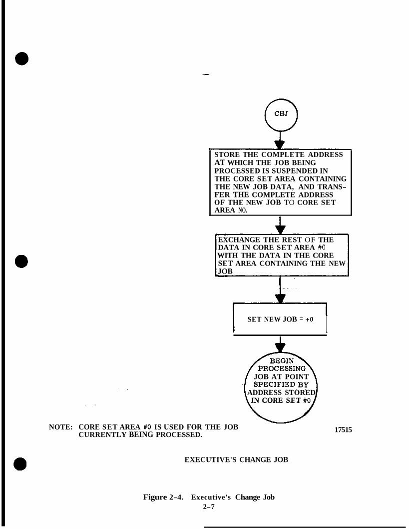
STORE THE COMPLETE ADDRESS AT WHICH THE JOB BEING PROCESSED IS SUSPENDED IN THE CORE SET AREA CONTAINING THE NEW JOB DATA, AND TRANS- FER THE COMPLETE ADDRESS OF THE NEW JOB TO CORE SET AREA NO.
EXCHANGE THE REST OF THE DATA IN CORE SET AREA #O WITH THE DATA IN THE CORE SET AREA CONTAINING THE NEW JOB
I SET NEW JOB = + O I
JOB AT POINT
ADDRESS STORED IN CORE SET #O
. .
. .
NOTE: CORE SET AREA #O IS USED FOR THE JOB CURRENTLY BEING PROCESSED.
17515
EXECUTIVE'S CHANGE JOB
Figure 2-4. Executive's Change Job 2-7

After this has been done, the Information stored in core set area # 0 , associated with the job being suspended, Is exchanged with the information contained In the core set area speci- fied by the number contained In NEWJOB. NEWJOB contains the relative address of the core set where the highest priority job's information is stored. By moving this infor- mation to core set # O , the processing of this job is enabled.
A f t e r the data is exchanged, NEWJOB is se t to + O . Then, the starting o r resumption address (whichever is applicable) of the highest priority scheduled job is read from core set area #O and is used to transfer control to the job. If the job is interpretive, the location address will be complemented prior to transferring control.
2 .1 .3 END OF JOB, JOB SLEEP, AND PRIORITY CHANGE SUBROUTINES. Since a major portion of these subroutines is identical, the subroutines are presented together.
The END OF JOB subroutine is used to remove a job from Executive consideration. This subroutine is %alledtT by the job which is to be terminated. Therefore, the job must be processed at the time it is terminated.
The JOBSLEEP subroutine is used to deactivate a job or willfully suspend the processing of the job. This subroutine is used by a job to deactivate itself o r put itself to sleep whenever it must wait for data, use of a piece of equipment o r for a particular condition to exist. When a job is put to sleep, the processing of lower priority scheduled jobs can be accomplished.
The PRIORITY CHANGE subroutine is used to change the priority of the job presently under execution. This subroutine is used by a job to change its own priority. This job will return to the caller a s soon a s its priority is again the highest.
The flow diagram for these three subroutines is shown in Figure 2-5. If the END OF JOB subroutine is used to terminate a job, the job is removed from the core set list by setting the priority register of core set area #O to negative zero. By doing this, the job is not only removed from the scheduling list, but this makes the core set area available for use by other jobs. After making the core set area available, a check is made to see if a VAC area was used by the job being terminated. If a VAC area was used, it is made available for use by other jobs by setting the address of the VAC USE register in that VAC USE regis- ter. This is an indication that VAC area is unreserved.
The remaining core set areas a re scanned to find the highest priority, nonsleeping job. After the core set areas a r e scanned, the highest active priority is checked to see if this job is DUMMY JOB. If it is, control is transferred to DUMMY JOB.
After the check is made for DUMMY JOB, an additional test is made to see if a job change is required. A job change will be required when the entry to this subroutine was from the END OF JOB subroutine subroutine and DUMMY JOB was not highest priority.
Control is transferred to the CHANGE JOB subroutine with the relative address of the core set area which contains the highest priority active job. The CHANGE JOB subroutine then uses this information to exchange the information in core set #O with the appropriate core set area and transfers control to the highest priority job.
2-8

STORE NEW PRIORITY
EXIT POINT OF JOB WHICH IS HAVING ITS
I PRIORITY CHANGED I
I I CHANGE PRIORITY NUMBER
MAKE CORE SET X0 AVAILABLE FOR USE BY OTHER JOBS
VAC AREA SED
MAKE VAC AREA AVAILABLE FOR USE BY OTHER JOBS
STORE ADDRESS OF EXIT POINT OF JOB TO BE PUT TO SLEEP IN CORE SET #O
COMPLEMENT PRIORITY NUMBER O F JOB & STORE IN CORE SET #O'S PRIORITY REG.
SCAN CORE SET AREAS FORJOB WITH HIGHEST PRIORITY
+
REQUIRED?
1"" ENTER CHANGE JOB WITH RELATIVE ADDRESS OF THE CORE SET CONTAINING THE HIGHEST PRIORITY IN NEW JOB 17559
Figure 2-5. Executlvels Prlority Change, End of Job and Job Sleep
2-9

The JOBSLEEP subroutine, see Figure 2-5, stores the complete address of the point in the job where it should be awakened. After this has been accomplished, the priority number stored in core set area #OB (which is the priority of the job being put to sleep) is complemented. This cause6 the contents of the register to become a negative quantity which signifies a sleeping job. Note that the job is still scheduled on the core set list but it has been put into an inactive state by complementing its priority register.
When the job has been put to sleep, the remaining core set areas are scanned to find the highest priority active job. After the core set areas are scanned, a check is made to determine if the highest priority active job is DUMMY JOB. If it is, control is transferred to DUMMY JOB. If DUMMY JOB is not the highest priority active job, a test is made to determine if a job change will be required. A job change will be required when the entry to this subroutine was JOBSLEEP.
Control is transferred to the CHANGE JOB subroutine with the relative address of the core set area's highest priority, active job. The CHANGE JOB subroutine again exchanges the information of the iobs contained in the core set areas so that the information for the job to be performed is in core set area #O. Then control is transferred to the job using the address stored in core set area #O.
The PRIOCHNG (Priority Change) subroutine, also shown in Figure 2-5, stores the new priority to be assigned to the job being processed. After thie has been accomplished, the complete address of the point that this job was at the time control wa8 transferred to PRIOCHNG is stored. The priority number contained in core set area #O is now changed to the new priority.
The remaining core set areas are now scanned to find the highest priority active job. After the scanning of the core set areas has been accomplished, a check is made to see if DUMMY JOB is the highest active priority. When PRIOCHNG subroutine is used, DUMMY JOB will not be the highest priority active job.
A check is now made to see if a job change is necessary. If the new priority assigned by the calling job to itself is still the highest, control is transferred to the caller. If it is not the highest, a job change will be required. The CHANGE JOB subroutine will ex- change the information in the core set area which has its relative address in NEWJOB with the information in oore eet area X O . Control le transferred to the new highest priority active job using the address stored in core set area #O.
2 .1 .4 DUMMY JOB SUBROUTINE. (See figure 2-6) The Dummy Job subroutine provides the computer with something to do if no other jobs require processing. It is performed under control of the Executive routine, is always scheduled to be processed, and has the lowest priority of any job. Therefore, any time there are no other active jobs scheduled on the job list, DUMMY JOB is processed.
Whenever Dummy Job is processed, the COMPUTER ACTIVlTY indicator is not illumi- nated. Any time another job is being processed under control of the Executive routine, the indicator is illuminated. This indicator i s extinguished whenever the DUMMY JOB is entered and is illuminated when the DUMMY JOB is left. The flow diagram of the Dummy Job is shown in figure 2-6. Control is transferred to thie subroutine through the Executive Change Job subroutine when the Dummy Job's priority is the ?!highestff of dl scheduled jobs. When control is routed to Dummy Job, the COM- PUTER ACTNITY indicator is extinguished by setting bit 2 of output channel 11 to a binary 0 .
2-10

0 DUMMY
w
SET NEWJOB = -0
i
TURN OFF COMPUTER ACTIVITY LAMP (SET CH11, BIT 2 = 0) I
YES (NEW JOB IN POSITION YES FOR EXECUTION)
TO PROCEE SE LF '
NO
I7558
Figure 2-6. Executive's Dummy Job
2-11
After servicing the COMPUTER ACTNlTY indicator, a check is made to determine if a new job of higher ptiority has been scheduled. This is accomplished by checking the con- tents of the NEWJOB register. The NEWJOB register is set to the relative address of the core set area reserved for a scheduled job if its priority is higher than the job presently being processed. If NEWJOB contains a core set number greater than + O , the COMPUTER ACTIVITY indicator is illuminated by setting bit 2 of output channel 11 to a binary one. Control is then routed to the Change Job subroutine which routes control to the highest priority job.
L€ the NEWJOB register contains a - 0 , control is transferred to the self check routine. Periodically during the self check routine, the NEWJOB register is checked to see if a job with a priority higher than Dummy Job is to be performed.
The self check routine has the capability to insert a +O into NEWJOB and to set up a special test a s a part of the self test routine. In this special test case, the COMPUTER ACTIVITY indicator is illuminated and the address of the new job which had previously been inserted into the A and L registers is inserted into the Z and BB registers, respec- tively.
2.1 .5 JOB WAKE SUBROUTINE. The JOB WAKE subroutine is used to wake up o r to reactivate a sleeping o r deactivated job. A job or task other than the sleeping job must awaken the sleeping job. The job o r task wishing to awaken a job must furnish the JOB WAKE subroutine with the awakening address of the sleeping job. This address was stored in the core set area of the sleeping job when it put itself to sleep. The awak- ening address supplied to the JOB WAKE subroutine is used to find the sleeping job.
The flow chart of the JOB WAKE subroutine is shown in Figure 2-7. On entry to this routine, the awakening address is available and is stored temporarily for use in this subroutine. After storing this address, the complete address of the return point of the job o r task using this routine is stored. This address is used to return control to the job o r task after awakening the job. When this has been accomplished, a scan of the job areas is initiated to find a sleeping job. When a sleeping job is found, the awakening address stored in the core set area is checked against the one supplied by the job or task using the JOB WAKE subroutine. I€ the job is not the correct job, the scan continues. If the sleeping job is not found, control is returned to the job or task which called for the use of the subroutine. However, if the sleeping job is found, the priority number is com- plemented, thereby reactivating or awakening the job.
The rest of the flow chart is identical to the end of NOVAC FINDVAC.
2-12

ENTER N T H C O V P L E T E ADDRESS OF POINT TO RESUMF SLEEPING JOB
4 SAVE COhtPLETE ADDRESS O F EXIT POINT OF PRM;. REQUESTING JOB \\‘AKE
(IN ORDER 0 - 6)
INCREMENT COUNTER
S E T NEWJOB - *o
FORCE T C T R A P
0 RESTART
I COMPLEMENT PRIORITY & STORE IN PROPER CORE I SET AREA. MAKE U P THE COMPLETE A1)I)RESS O F THE A\\AKENED JOB
I No
ADDRESS OF JOB IN RESERVED CORE
YES
S E T NEW JOB T O CORE S E T AREA RESERVED FOR AU’AKENED JOB ,7s,
Figure 2-7. Executive’s Job Wake
2-13
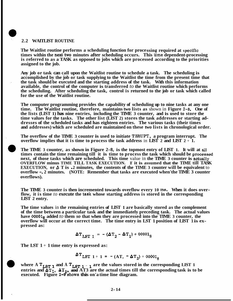
2.2 WAITLIST ROUTINE
The Waitlist routine performs a scheduling function for proce ssing required at sp becific times within the nexttwo minutes after scheduling occurs. This time dependent-processing is referred to as a TASK as opposed to jobs which are processed according to the priorities assigned to the job.
Any job or task can call upon the Waitlist routine to schedule a task. The scheduling is accomplished by the job or task supplying to the Waitlist the time from the present time that the task should be executed and the starting address of the task. With this information available, the control of the computer is transferred to the Waitlist routine which performs the scheduling. After scheduling the task, control is returned to the job or task which called for the use of the Waitlist routine.
The computer programming provides the capability of scheduling up to nine tasks at any one time. The Waitlist routine, therefore, maintains two lists as shown in Figure 2-8. One of the lists (LIST 1) has nine entries, including the TIME 3 counter, and is used to store the time values for the tasks. The other list (LIST 2) stores the task addresses or starting ad- dresses of the scheduled tasks and has eighteen entries. The various tasks (their times and addresses) which are scheduled are maintained on these two lists in chronological order.
The overflow of the TIME 3 counter is used to initiate T3RUPT, a program interrupt. The overflow implies that it i s time to process the task address in LIST 2 and LIST 2 + 1.
The TIME 3 counter, as shown in Figure 2-8, is the topmost entry of LIST 1. It will at all times contain the time remaining till it is time to process the task which should be processed next, of those tasks which are scheduled. This time value in the TIME 3 counter is actually OVERFLOW minus TIME TILL TASK EXECUTION. If it is assumed that the TIME till TASK EXECUTION, or r?, T is . 2 minutes, the contents of the TIME 3 counter will be equivalent to overflow -. 2 minutes. (NOTE: Remember that tasks are executed when'the TIME 3 counter overflows).
The TIME 3 counter is then incremented towards overflow every 10 ma. When it does over- flow, it i s time to execute the task whose starting address is stored in the corresponding LIST 2 entry.
The time values in the remaining entries of LIST 1 are basically stored as the complement of the time between a particular task and the immediately preceding task. The actual values have OOOOlg added to them so that when they are processed into the TIME 3 counter, the overflow will occur at the correct time. The time entry in LST 1 position of LIST 1 is ex- pressed as:
The LST 1 + 1 time entry is expressed as:
'TIST 1 + 1 = - (AT, - AT2) + O O O O l g
where A TLST and A TLST + are the values stored in the corresponding LIST 1 entries and AT1, AT , and AT3 are the actual times till the corresponding task is to be executed. Figure 2-#shows this on'a time line diagram.
2- 14

TASKTIMES - LIST 1
(=I TIME 3
LST 1 E3, 1400
LST 1 + 1 E3, 1401
L S T 1 + 2 E3, 1402
LST 1 + 3 E3, 1403 I LST 1 + 4 E3, 1404
~~
LST 1 + 5 E3, 1405
LST 1 + 6 E3, 1406
LST 1 + 7 E3, 1407
TASK ADDRESSES - LIST 2 (2 CADR)
f 3 GEN ADDR BBCON
LST 2 E3, 1410 LST 2 + 1 E3, 1411 I I,
LST 2 + 2 E3, 1412
LST 2 + 17 E3, 1431 LST 2 + 16 E3, 1430
LST 2 -t- 15 E3, 1427 LST 2 + 14 E3, 1426
LST 2 + 13 E3, 1425 LST 2 + 12 E3, 1424
LST 2 + 11 E3, 1423 LST 2 + 10 E3, 1422
LST 2 + 9 E3, 1421 LST 2 + 8 E3, 1420
LST 2 + 7 E3, 1417 LST 2 + 6 E3, 1416
LST 2 + 5 E3, 1415 L S T 2 + 4 E3, 1414
LST 2 + 3 E3, 1413
NOTE: 1. TIME 3 is associated with LST 2 and LST 2 + 1, LST 1 is associated with LST 2 + 2 and LST 2 + 3, etc.
LST 2 + 17 should contain the starting address of ENDTASK. The Waitlist routine will transfer control to the abort routine which in- itiates the failure displays and the restart routine when the next entry is made if ENDTASK is not as indicated above.
3. All scheduled tasks are tabulated in chronological order in LIST 1 and LIST 2. If two tasks a re scheduled to be done at the same time, the task scheduled first will be done first.
4. The eraeable memory address of each register used as a part of the list is shown following the register name as 0026 o r E3, 1400, etc. These numbers a re in octal.
2. LST 1 + 7 should contain the time for ENDTASK and LST 2 + 16 and
Figure 2-8. Waitlist's Waiting List
2-15

T o = PRESENT TIME
T1, 2, 3, 4
A%, 2, 3, 4
AT^^^ 1
AT^^^ 1 + 1
= TIME AT WHICH TASKS ARE PROCESSED
= TIME FROM PRESENT TO PROCESS TASK
ATT3 = TIME VALUE FOR TIME 3 COUNTER (OVERFLOW - AT1)
= TIME VALUE FOR LIST 1 = C - (AT, - AT1) + 0000181
= TIME VALUE FOR LIST 1 + 1 =[ - (AT3 - AT,) + 0 0 0 0 1 8 ~
Figure 2-9. Time Values Stored in List 1
2-16
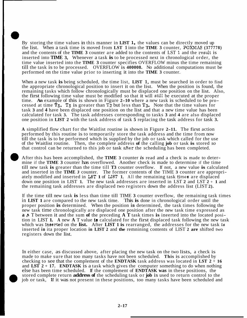
By storing the time values in this manner in LIST 1, the values can be directly moved up the list. When a task time is moved from LST 1 into the TIME 3 counter, POXMAS (377778) and the contents of the TIME 3 counter a re added to the contents of LST 1. and the result is inserted into TIME 3, Whenever a task is to be processed next in chronological order, the time value inserted into the TIME 3 counter specifies OVERFLOW minus the time remaining till the task is to be processed. OVERFLOW is 400008. No additional computations must be performed on the time value prior to inserting it into the TIME 3 counter.
When a new task is being scheduled, the time list , LIST 1, must be searched in order to find the appropriate chronological position to insert it on the list. When the position is found, the remaining tasks which follow chronologically must be displaced one position on the list. Also, the first following time value must be modified so that it will stfiZ be executed at the proper time. An example of this is shown in Figure 2-10 where a new task is scheduled to be pro- cessed at time T5, T5 is greater than T2 but less than T3. Note that the time values for task 3 and 4 have been displaced one position on the list and that a new time value has been calculated for task 3. The task addresses corresponding to tasks 3 and 4 are also displaced one position in LIST 2 with the task address of task 5 replacing the task address for task 3.
A simplified flow chart for the Waitlist routine is shown in Figure 2-11. The first action performed by this routine is to temporarily store the task address and the time from now till the task is to be performed which is supplied by the job or task which called for the use of the Waitlist routine. Then, the complete address of the calling job or task is stored so that control can be returned to this job or task &er the scheduling has been completed.
After this has been accomplished, the TIME 3 counter is read and a check is made to deter- mine if the TIME 3 counter has overflowed. Another check is made to determine if the time till new task is greater than the time till T3 counter overflow. If not, a new value is calculated and inserted in the TIME 3 counter. The former contents of the TIME 3 counter are appropri- ately modified and inserted in LST 1 of LIST 1. A l l the remaining task times are displaced down one position in LIST 1. The new task addresses are inserted in LST 2 and LST 2 + 1 and the remaining task addresses are displaced two registers down the address list (LIST 2).
If the time till new task is less than time till TIME 3 counter overflow, the remaining task times in LIST 1 are compared to the new task time. This is done in chronological order until the proper position is determined. When the position in determined, the task times following the new task time chronologically are displaced one position after the new task time expressed as a A T between it and the sum of the preceding A T task times is ineerted into the located posi- tion in LIST 1. A new A T value is calculated for the first displaced task following the new task which was inaerted on the list. After LIST 1 is rearranged, the addresses for the new task is inserted in ita proper location in LIST 2 and the remnining contents of LIST 2 are shifted two registers down the list.
In either case, as discussed above, after placing the new task on the two lists, a check is made to make sure that too many tasks have not been scheduled. This is accomplished by checking to see that the complement of the ENDTASK task address was located in LST 2 + 16 and LST 2 + 17. ENDTASK is a task which gives the computer something to do when nothing else has been time scheduled. If the complement of ENDTASK was in these positions, the stored complete return address of the scheduling task o r job is used to return control to the job or task, If it was not present in these positions, too many tasks have been scheduled and
2-17
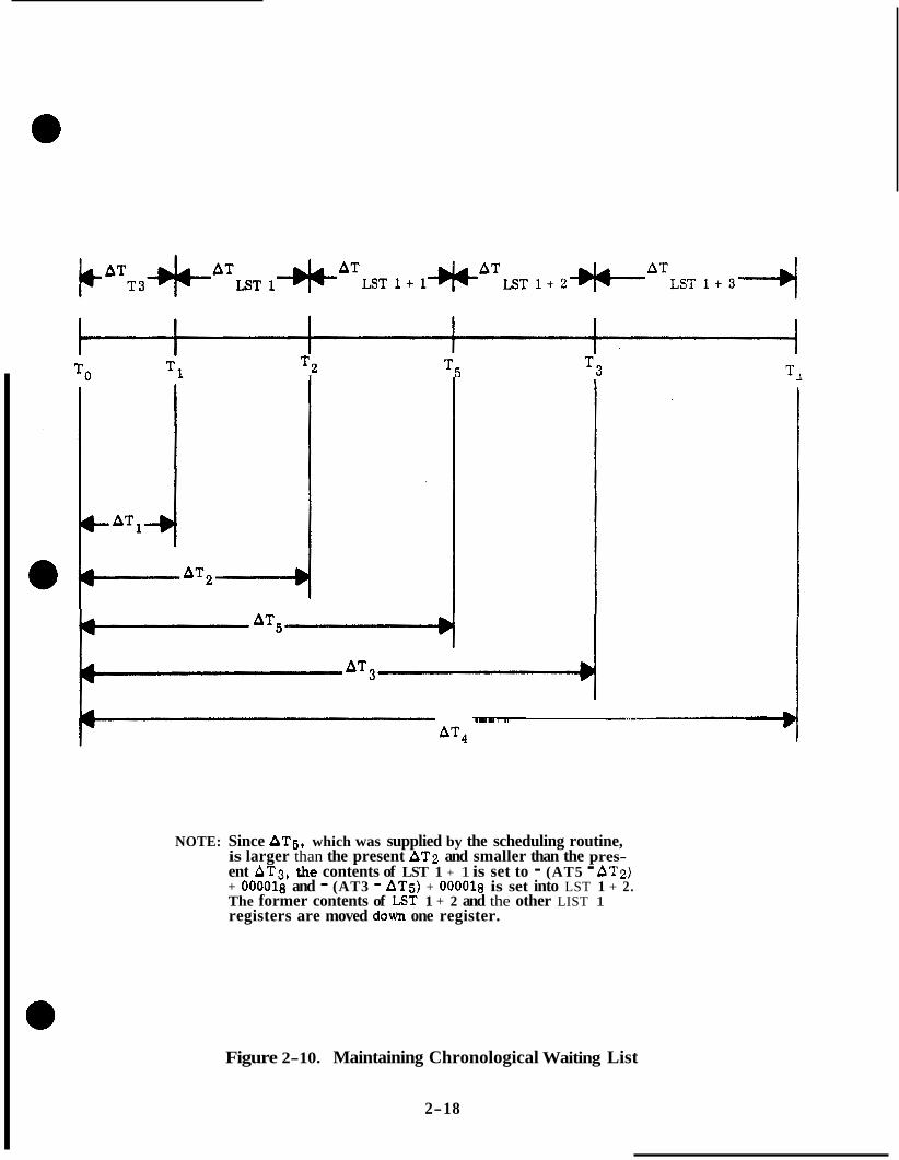
TO T1 T Z I
FAT5- 1 AT4
NOTE: Since AT5, which was supplied by the scheduling routine, is larger than the present AT2 and smaller than the pres- ent AT3, the contents of LST 1 + 1 is set to - (AT5 - ATz) + O O O O l 8 and - (AT3 - AT5) + OOOOlg is set into LST 1 + 2. The former contents of LST 1 + 2 and the other LIST 1 registers are moved down one register.
Figure 2-10. Maintaining Chronological Waiting List
2-18

INCREMENT LIST 1
LIST 1 LST CAN BE INTERROGATED FOR
* PICK CP & STONE TINE TILL TASK & TASK ADIIRESS
STORE RETURN ADDRESS O F CA LLMG PROGRAhl
r + READ T3 COUNTER AND CORRECTFOROVER- FLOW IF REQZ'IRED
t
1 i
., < PROGRAM CAZ'TION
I t1 . 01203
TOO MANY TASKS) a FORCE TC TR.AP
0 RESTIZRT
IFSERT ATNEH. TASK ISTO API'HOPI~IATk: LIST I LST
IC ,
+ CALC. NEW A T VALLIE:
TASK FOR NEkT FOLID\VMG
SHIFT REalAINING L I S T 1 TIMES DONN ONE POSITION
1 I
CORRESPONDING TO POSITION IN LIST '2
THE LIST 1 ENTRY O F RETI'RN
17387
Figure 2-11. Waitlist
2-19

the PROGRAM CAUTION indicator is illuminated. Also, VERB 05, NOUN 31 are displayed along with 01203 in the DSKY register R1. The number 01203 indicates that there has been a Waitlist Overflow o r that too many tasks have been scheduled. Then a TC TRAP condition is forced causing the execution of the RESTART routine,
2 . 3 TIME 3 PROGRAM INTERRUPT ROUTINE (T3RUPT)
The T3RUPT routine is initiated by the overflow state of the TIME 3 through a circuit forcing function. The TIME 3 counter is set to overflow at specific times according to the informa- tion supplied to, and the scheduling performed by, the Waitlist routine. Therefore, whenever the TIME 3 counter overflows, it is time to process a particular task.
The T3RUPT routine is used to initiate the processing of the task which was scheduled to be processed at the time of the TIME 3 counter overflow. The routine also moves all the task times and addresses up one register position in LIST 1 and two registers in LIST 2. The result of this is the loading of the TIME 3 counter with a new time value to increment towards overflow.
Figure 2-12 contains the flow chart for the T3RUPT routine. Entry to this routine is forced whenever the TIME 3 counter overflows through the program interrupt priority control cir- cuit of the computer. The first action performed by this routine is to enter a value of 577778 on the bottom of LIST 1. This is the time value for the ENDTASK task which corresponds to a time to overflow, when inserted into the TIME 3 counter, of approximately 82 seconds. After this has been accomplished, all of the time values of LIST 1 a r e moved up one position in the list. The contents of the TIME 3 counter are added to the time value from LST 1 which is to be inserted into the TIME 3 counter and POSMAX (377778). The contents of the TIME 3 counter is added to the contents to be inserted into TIME 3 counter because the counter could have been incremented since overflow because of delays in initiating the pro- cessing caused by the overflow condition. This could be caused by a combination of inhib- iting interrupts and the scheduling of more than one task to be processed at a particular time. By adding the contents of the TIME 3 counter to the next time value, the correct times are maintained for the remaining tasks if the delay in processing occurs. Note that if the counter has not been incremented since overflow, this addition has no effect, POSMAX is added to prepare the value for overflow when inserted into the TIME 3 counter.
A flag is set so that if the value inserted in TIME 3 was in overflow, the overflow wlll not be lost during the following operation. This is accomplished by setting RUPTAGN to +1 if the value inserted into TIME 3 was in overflow. If the value set into TIME 3 was not in over- flow, RUPTAGN will be set to - 0 .
Having completed the manipulations on LIST 1, LIST 2 must be serviced. The complement of the contents of ENDTASK is inserted in LST 2 + 16 and LST 2 + 17. After this has been accomplished, all of the task addresses stored in LIST 2 are moved up two registers. The address moved out of LST 2 and LST 2 + 1 rcgisters, as a result of this operation, is used to transfer control to the desired task. When control is returned to the I'SRUPT routine, n check is made to determine if the TIME 3 counter is again in the overflow state by checking RUPTAGN. If the TIME 3 counter has overflowed, control is routed to the beginning of the T3RUPT routine which is processed again. If it is not in the overflow state, control is re- turned to the job which was interrupted.
2-20
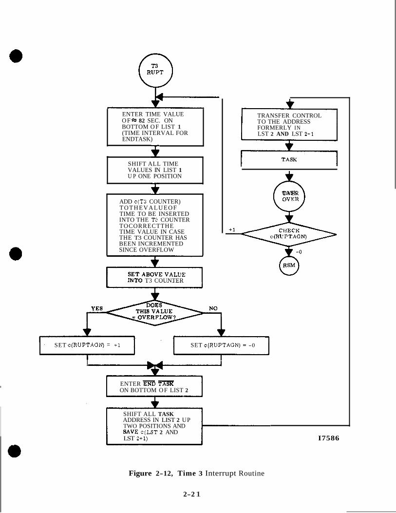
ENTER TIME VALUE O F 82 SEC. ON BOTTOM O F LIST 1 (TIME INTERVAL FOR ENDTASK)
- SHIFT ALL TIME VALUES IN LIST 1 U P ONE POSITION
ADD c(T3 COUNTER) T O T H E V A L U E O F TIME TO BE INSERTED INTO THE T3 COUNTER TOCORRECTTHE TIME VALUE IN CASE THE T3 COUNTER HAS BEEN INCREMENTED SINCE OVERFLOW
INTO T3 COUNTER
+ 1
TRANSFER CONTROL TO THE ADDRESS FORMERLY IN LST 2 AND LST 211
0 OVER
SET c(RUPTAGN) = +1 SET c(RUPTAGN) = -0
I
ENTER END TASK ON BOTTOM O F LIST 2
SHIFT ALL TASK ADDRESS IN LIST 2 UP TWO POSITIONS AND SAVE c(LST 2 AND LST 2+1) I7586
Figure 2-12, Time 3 Interrupt Routine
2-2 1

2.4 PHASE TABLE MAINTENANCE ROUTINE
The PHASE TABLE MAINTENANCE Routine consists of a group of subroutines which provide the initiation, termination, and progression through the mission o r testing routines of the computer. The mission o r testing routines are sometimes referred to as mission programs, testing programs o r major modes. Throughout the description of the PHASE TABLE MAIN- TENANCE Routine, these routines will be termed major modes programs. The major mode programs supply the information required for the display of the program number on the DSKY's. Each of the major mode programs is assigned a program number which is displayed wUe the program is being processed.
Each of the major mode programs is divided into a number of different phases. The PHASE TABLE MAINTENANCE Routine maintains a table for phase numbers for the major mode programs. The phase numbers are used to control the routing and progression through a major mode program. Also, if a failure occurs and requires a restart, the phase numbers stored in the phase table a re used to control the restarting of the major mode program at a particular phase of the program. The processing of the program would not necessarily begin at the beginning of the program nor at the phase specified by the phase number.
The phase table, where the phase numbers of the various major mode programs are stored, is actudly maintained in duplicate. This is done to assure that the correct phase number is obtained if a failure occurs. The two copies of the table a re called -PHASE and PHASE. -PHASE stores the complement of the phase number while PHASE stores the actual phase number. The phase tables consist of twelve registers.
2 . 4 . 1 PHASE CHANGE AND NEW PHASE SUBROUTINES. The PHASE CHANGE and NEW PHASE subroutines of.the PHASE TABLE MAINTENANCE Routine are used by the major mode programs to change its phase number which is stored in duplicate in the phase tables o r to initialize the phase tables for some major mode program operation. A flow chart of these subroutines is shown in figure 2-13. Except for the 'lead-inff op- eration, the two subroutines are identical and perform the same function.
The PHASE CHANGE (PHASCHNG) subroutine is called by
L TC PHASCHNG
Lt-1 OCT PPP GG
When transferring control to the PHASCHNG subroutine, the contents of the address in the Q register contain the phase number PPP in the three most significant octal digits. It also contains the group number in the two least significant digits. The contents of the Q register are masked to acquire the group number. This number is doubled and becomes the phase table relative address for use in indexing. The phase number is shifted two octal digits to the right and is stored in the A register.
The NEWPHASE subroutine is called by
L- 1 CA PPPPP
L TC NEWPHASE
Id1 OCT 0 0 0 G G
2-22
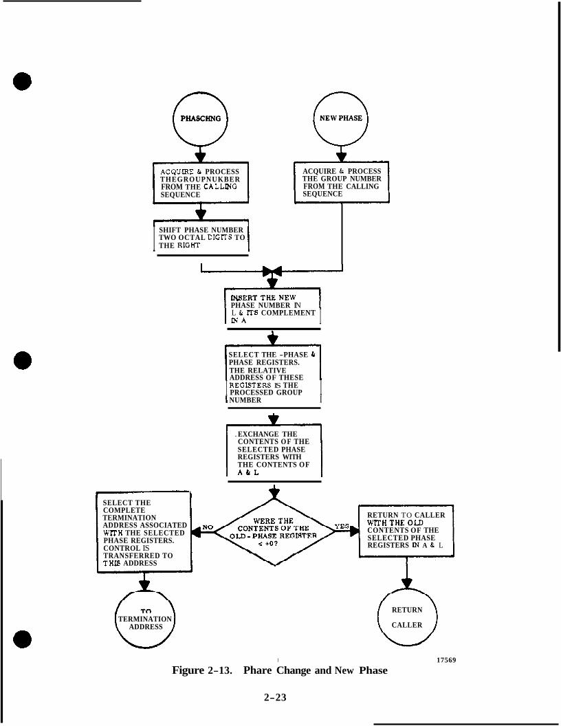
0 PHASCHNG
THEGROUPNUKBER ACQUIEtE & PROCESS
SEQUENCE FROM THE CALLPJG
I TWO OCTAL DIGFr'S TO SHIFT PHASE NUMBER
THE RIGHT
0 NEW PHASE
ACQUIRE & PROCESS THE GROUP NUMBER
SEQUENCE FROM THE CALLING
PHASE NUMBER IN
I I N A L & mS COMPLEMENT I
SELECT THE -PHASE & PHASE REGISTERS. THE RELATIVE ADDRESS OF THESE
I REGIE~TERS IS THE PROCESSED GROUP I
I NUMBER I
. EXCHANGE THE CONTENTS O F THE SELECTED PHASE REGISTERS WITH THE CONTENTS OF
L I
SELECT THE
TERMINATION COMPLETE
ADDRESS ASSOCIATED W m H THE SELECTED PHASE REGISTERS. CONTROL IS TRANSFERRED TO THIS ADDRESS
RETURN TO CALLER
CONTENTS OF THE SELECTED PHASE REGISTERS LN A & L
TERMINATION ADDRESS
RETURN
CALLER
1
Figure 2-13. Phare Change and New Phase
2-23
17569

Therefore, when control is transferred to NEWPHASE, the phase number is in the A register. The contents of the address in Q contains the group number. The group num- ber is doubled and becomes the relative address of phase table.
From this point on, PHASCHNG and NEWPHASE are identical, The new phase number, which is in the A register is stored in the L register and the contents of the A register are complemented. The group number is used to index the desired phase table registers, a -PHASE and PHASE. The contents of the selected -PHASE and PHASE registers are exchanged with the contents of the A and L registers, respectively, The former contents of the -PHASE register are checked to determine if they were equal to or less than pos- itive zero. If the answer is yes, the subroutines return control to the caller with the old contents of -PHASE and PHASE in the A and L registers, respectively. If the answer is no, control is transferred to the termination address associated with the selected phase table registers.
2 .4 .2 NEW MODE EXCHANGE SUBROUTINE. The NEW MODE EXCHANGE (NEW- MODEX) Subroutine of the PHASE TABLE MAINTENANCE Routine is used by various major mode programs to set up the major mode program number which will be displayed on the DSKY by the T4RUPT routine. If the new major mode program number is the same as the present number, no change in the program number display i s made by the T4RUPT routine. (See Figure 2-14.)
Control is transferred to NEWMODEX by the caller with the address of the major mode 0 program number in the Q register. The program number is stored in MODREG. MOD- REG contains the present or new program number. The old contents of MODREG are compared to the new program number. If the two program numbers are the same, con- trol is transferred to the caller. If the old and new program numbers a re not in agree- ment, the new program number has to be set up for DSKY display. The relay code for the most significant of the two octal digits is acquired from RELTAB (Relay Code Table). The contents of DSPTAB+lOD are saved and the relay code is inserted into bits 6 through 10. The relay code for the least significant digit is acquired from RELTAB and inserted into bits 1 through 5 of DSPTAE!+lOD. Control is returned to the calling routine. The T4RUPT routine will cause the program number on the DSKY to be changed to the new number.
2.4.3 CHECK MAJOR MODE SUBROUTINE. The CHECK MAJOR MODE subroutine of the PHASE TABLE MAIXTENANCE Routine is used by various major mode programs to sample the program number of the major mode programs in process. The data i s used for routing purposes by the major mode program which uses this subroutine. (See Figure 2-15. )
Control is transferred to the Check Major Mode (CHECK" ) subroutine with the address of the check number in the return address (Q) register. The check number is comple- mented and added to the contents of MODREG. The contents of MODREG will be equiv- alent to the program number displayed on the DSKY. If the contents of MODREG and the check number are in agreement, the contents of the accumulator will be negative zero. Branching to the next subroutine is dependent upon the contents of the accumulator and the contents of the two addresses following the address in Q . The exact action resulting from these two return points is dependent on the major mode program which called this @ subroutine.
2-24

0 NE WMODEX
STORE NEW MAJOR MODE PROGRAM NUMBER IN NEWMODE REGISTER
ACQUWE THE RELAY CODE FOR THE MOST SIGNIFICANT DIGIT FROM RE LTAB (RE LAY CODE TABLE)
1
4
SAVE OLD CONTENTS OF DSPTAB+lOD
v 1
INSERT RELAY CODE I N B l " S 6 - 1 0 0 F DSPTAB+lOD
ACQUIRE THE RELAY CODE FOR THE LEAST SIGNIFICANT DIGIT FROM RELTAB
INSERT RELAY CODE I N B R S l - 5 O F DSPTAB+lOD
A I pJ CALLER
Figure 2-14. New Mode Exchange
2-25

0 CHECKMM
ADD THE CONTENTS OF THE MODREG REGISTER TO THE COMPLEMENT OF THE MAJOR MODE CHECK NUMBER
THE MAJOR\ P W U P K NTTMRER YES
SUBROUTINE SUBROUTINE
17568
Figure 2-15. Check Major Mode
2-26

SECTION I11
INPUT/OUTPUT CONTROL ROUTINES
INTRODUCTION
This section of the study guide presents the routinee used to perform input and output func- tions of the LGC. . The routines are ueed by most of the programs of the LGC to perform the required input and output functions. Through these routines, the LGC is capable of com- manding spacecraft system modee, displaying and accepting information from the DSKYIs and Radar providing for telemetry input8 and outputo, controlling the positions of the RR antenna and the stable member, and remaining cognlzant of the PGNCS and other spacecraft system operatione.
3 . 1 TIME 4 COUNTER PROGRAM INTERRUPT ROUTINE (T4RUPT)
The TIME 4 COUNTER program interrupt routine (T4RUPT routine) is initiated whenever the TIME 4 counter overflows. Normally this time counter is set so that it will overflow every 120 ms. Everytime it overflows, the T4RUPT routine is initiated and one o r more of the following functions are performed:
a. Updating the forward and lateral velocity meters and altitude meter.
b. Sampling and verification of the ISS mode of operation including turn-on.
c. Sampling and verification of the Radar mode of operation.
d. Monitoring the telemetry rates.
e. Sampling of malfunction indications from the ISS.
f. Control of the relays of the DSKY's for display of information, for commanding ISS, and other spacecraft modes, and for control of indicator panel'illumination. g. Servicing the RR mode requests and RR CDU fail inbit. h. Update the gimbal to pilot matrix. All of the programs which desire to perform any of the functions listed, provide the information to the T4RUPT routine. The T4RUPT routine then uses the supplied informa- tion to perform the appropriate input o r output function. In return, the T4RUPT routine furnishes information to the other routines or processing functions indicating the results of a desired action.
A deviation from the normal 120 ms rate at which the T4RUPT routine occurs is if the relays a r e manipulated. Whenever relays are driven, the TIME 4 counter is set to overflow in 20 o r 30 ms. This is done so that the driving of the relay coils is terminated after a sufficent amount of time for the relays to latch into the proper configuration. This also prevents ex- cessive heat build up and power consumption. After a 20 o r 30 ms rupt has occurred, a 100 o r 90 ms rupt is scheduled respectively, so that the nominal 120 ms interrupt rate is main- tained.
3-1

Figure 3-1 is a general flow diagram of the T4RUPT routine. Following this a more detailed flow chart of the routine is presented. The general flow chart is presented to enable the student to obtain an overall knowledge of what is accomplished by this routine and in what order it is accomplished.
Referring to figure 3-1, entry is forced whenever the TIME 4 counter overflows. This occurs every 120 msec (with the exception of when DSKY or LMP relays have been driven). The dis- play tables a re serviced every 120 msec. This implies the capability of displaying new infor- mation or change in information every 120 msec, thus providing the operation ffcontinuouslyff updated information.
After servicing the DSPTAB's, a check is made to determine the pass through the T4RUPT routine. This is determined by looking at a counter which is initially set to 7 and is decre- mented every time a 120 ms interrupt routine is processed. Therefore, the counter expresses eight states; 7 , 6, 5, 4, 3, 2, 1 and 0, Whenever the counter goes to 0, it is set to 7. This counter is used to determine which of the 5 subroutines of the T4RUPT routine is to be processed for this interrupt.
Noting the numbers adjacent to the lines one sees that when the counter is in the 3 or 7 state the G P matrix is updated. If the counter is in state 0 the forward and lateral velocity meters along with the altitude meter receive updating. The counter in the 2 or 6 state routes ser- vicing to the ISS failure, turn-on, and gimbal Iock monitoring. Counter state 1 or 5 forces the T4RUPT into monitor the RR CDU fail inbit in addition to servicing RR moding and posi- tioning. Counter state 4 forces an update of the forward and lateral velocity meters and an update of the altitude rate meter.
The following sections present detailed flow diagrams (figure 3-3 is located at the end of this chapter) illustrating how the program executes the T4RUPT routine,
3 . 1 . 1 T4RUPT LEAD IN, 20, 30 MSEC RUPT, SERVICE DSPTABS. The overflow of the TIME 4 counter forces the program interrupt T4. The first operation after trans- ferring control to the T4RUPT program is to store the address of the exit point of the interrupted program to enable a return to the interrupted program at the completion of the specific T4RUPT routine, Setting the output channel 10 to zero removes the drive cur- rent to the DSKY relays. This is done regardless of whether DSKY relays were set or not on the previous pass through T4RUPT.
The contents of memory register T4LOC is checked to identify what type of interrupt this is. If it was either a 20 or 30 msec rupt approximate routing is accomplished to keep the total normal time equal to 120 msec. Thus for a 20 msec rupt, 100 msec is added prior to going through the normal T4 routing, for a 30 msec rupt, 90 sec are added in real time.
Then, the contents of memory register, DSRUPTSW (DISPLAY RUPT), is checked. Whenever the normal 120 m s interrupt occurs, the DSRUPTSW will be positive or positive zero. If i t is positive, the contents of DSRUPTSW is decremented or if it is positive zero, it is set to 7. The decrementing and setting to 7 of the DSRUPTSW is used to control the routing to the various subloops of the T4RUPT routine. The contents of DSRUPTSW is used in this manner later in the routine.
3-2

I SERVICE DSPTARS AND LMP CMDS I SET T4 COUNTER TO OVERFLOW IN THE APPROPRIATE TIME
SERVICE T4 ROUTING CONTROL IT4 LOC AND DSRUPTSW)
960 MSEC 0 WHICH PASS THROUGH T4 RUPT? (DSRUPTSW)
960 MSEC
A LTOUT
UPDATE FWD AND 1 , 5 2 , 6 G P MATRIX LAT VEL. METERS 480 480
MSEC MSEC UPDATE G P MATRIX
r 1 .
I I MONITOR RRCDU FAIL AND SERVICE RR MODE
I UPDATE G P M A T R M I
IMU MON
SERVICE CH 30 STATE CHANGES (BITS 9, AND 11-15)
~~~~~~~~~ ~~~~~ ~ ~ ~~~~~
PROCESS TURN ON REQUEST
SERVICE CH 33 STATE CHANGES (BITS 11 - 13)
CHECK FOR GIMBAL LOCK
! ALTROUT
UPDATE FWD AND LAT VEL. METERS
UPDATE ALT. RATE METER
J
I8523
Figure 3-1. General T4RUPT
3-3

A check of the word in memory called LMPCMD is made. This word acts a s a pseudo DSPTAB and is used for setting particular relays associated with LM interfacing. A unique requirement calling for a 30 msec "power on time" rather than the DSKY relay 20 msec on time. Assuming that a LMPCMD is required, flag bit 15 is reset so that this route won't be forced next pass. A special relay code of 740008 is added to the marked low order eleven bits that were in LMPCMD and the relay bits and code are placed in output channel 10. After the data is in channel 10 the time 4 counter is set to overflow in 30 msec and the appropriate routing is placed in T4LOC. Now the interrupted program is resumed.
Assuming a LMPCMD is not required a check of DSPTAB 11 is made. Lf it is negative some other program has made the request for a display of one or more of the items listed for DSPTAB 11. Note table 3-1 which depicts the contents of all display tables. At this point a brief discussion on the mechanism of displaying information will be presented.
Referring to figure 3-2, note that there is an interrelationship between a calling program, the T4RUPT routine, and the output channel 10, The calling program (which desires a display) supplies the appropriate code for the display to the appropriate DSPTAB. If it is a character display for R1, R2, R3, a verb-noun or program number, the low order 9 DSPTAB's a r e used. The calling program places the code in the correct DSPTAB and sets the sign of that DSPTAB negative (i. e. , bit 15 = 1). This bit 15 will identify to the T4RUPT program that the contents of that particular display table requires processing. Notice bits 12 - 14 a r e not used in the DSPTAB word. Only the low order 11 bits (and bit 15) have any significance. By virtue of the address of the particular DSPTAB a 4 bit code is assigned. This 4 bit code is a relay code whose sole function is to apply ground to the appropriate relay bank associated with the desired display.
T4RUPT scans the DSPTAB's every 120 msec starting at DSPTAB 11. If a particular DSPTAB is negative, T4RUPT "attaches" the particular relay code to the low order relay bits and places the resulting 15 bits into output channel 10 which, in turn, results in the activation of the appropriate relays causing the desired display,
I€ a requirement to drive a C relay exiets, reset bit 15 so that on the next pass a redisplay of identical data will not occur. Then, extract low order 11 bits (relay bits) and attach associated 4 bit relay code.
Transfer the entire 15 bit display word into output channel 10 and identify 20 msec RUPT. This allows sufficient time for the latching relays to pull in.
If there is not display requirements in DSPTAB 11 each of the DSPTAB's 10 - 0 are checked twice, If a display is required, bit 15 is reset and its code and command are set into output channel 10.
If no displays are required the normal 120 msec RUPT is set up and the contents of DSRUPTSW is checked to identify the pass W.
3-4

Bit 1 2 3 4 5 6 7 8 9 10 11
DSPTAB+llD No Gimbal Tracker Program Att Lock Warning Caution
I DSPTAB+ 10D I MD1 (5 bit Relay Code) MD2 (right hand character)
DSPTAB+ 9D
ND2 ND1 I3SPTAB-t 8D
VD2 VD1
I DGPTAB+7 I R l D l (left hand character)
DSPTAB+ 6
R1D5 (right hand character) -RlS R1D4 DSPTAB+ 5
R1D3 + R1S R1D2
I DSPTAB+4 I i R 2 S R2D1
DSPTAB+ 3 -R2S R2D3
R3 D l R2D5 DSPTAB+ 2
R2D4 ~ ~~ ~ ~ ~~~ ~~~
~
DSPTAB+ 1
R3D5 -R3S R3 D4 DSPTAB
R3 D3 + R3S R3D2 ~~~
Table 3-1. The 12-Word Display Table Bit Assignments

A D I S P L A Y AND S U P P L I E S
I A P P R O P R I A T E 11 B I T CODE TO A P P R O P R I A T E D S P T A B
~ ~"
F I X E D CODE ' I P R O V I D E D FOR ( R E L A Y BITS) EACH D S P T A B FRoM MEMORY
D S P T A B l o
I r r l l - l ~ ~ ~ J ~ 1 0
/ T4RUPT SCANS A N D
INFORMATION C ( D S P T A B ) + CODE A S S E M B L E S DISPLAY
C H A N N E L
D S P T A B CODE IDS WHICH RELAY(S) ARE TO B E E N E R G I Z E D
. .. . ..." ~ _"."
-.
Figure 3-2. DSPTAB Code
3-6
Assuming we are on pass 0, control i s rerouted to the ALTOVT portion of the T4RUPT routine.
3 . 1 . 2 ALTOUT. This routine is entered every 960 msec or every eighth pass through the T4RUPT routine when the contents of DSRUPTSW is equal to zero. The purpose of this subroutine is to update the altitude and forward and lateral velocity meters. The ALTROUT subroutine uses a portion of the ALTOUT subroutine and also updates the forward and lateral velocity meters. The forward and lateral velocity meters are updated every 480 msec.
The computer receives altitude, altitude rate and forward and lateral velocity information from the landing radar; this information is used in developing the various display drive signals. The altitude display data is transferred into the ALTM output counter and gated out to the altitude meter, The forward and lateral velocity display data is transferred into the OPTXCMD and OPTYCMD output counters and gated out to their respective meters. The actual gating out of information does not begin until output channel 14 bits 3, 11 and 12 are se t to equal 1. Forward and lateral velocity information is applied to the RR CDU er ro r counters where it is converted from digital to analog information. The information is then routed to the altitude meter for display, The altitude information is gated directly to the altitude meter, the altitude meter converts the information from digital to a visual readout. Altitude information can be calculated by multiplying the altitude rate by the loop time (. 96 sec) to develop the change in altitude, and by subtracting the altitude change from the last altitude, the latest altitude can be generated.
3 . 1 . 3 ALTROUT. The ALTROUT subroutine is entered every 960 msec or every time the contents of the DSRUPTSW is equal to 4. The purpose of this subroutine is to update the altitude rate meters display. The ALTROUT subroutine updates the forward and lateral velocity meters as well as the altitude rate meter.
3 . 1 . 4 RR AUT CHK (RENDEZVOUS RADAR AUTOMATIC CHECK). The T4RUPT program does this routine every 480 msec. RRAUTCHK services the RR inbits and drives the antenna. Erasable memory location RADMODES is updated to the latest RR condition every time the RR inbits change. See table 3-2.
If the RR AUTO MODE bit of channel 33 changes, a check is made to determine whether it just came on o r just went off. The RR AUTO MODE bit just going off while a program is using the radar causes a PROGRAM CAUTION and the failure is displayed in R1 of the DSKY. If the RR AUTO MODE bit just came on while no other program was using the radar, the RR TURN-ON is initiated by scheduling the RR TURN-ON task.
The RR TURN-ON task: zeroes the radar CDU channels, sets the computer RR CDU counters to zero, sets RADMODES to agree with the antenna angles, and lights the TRACKER WARNING lamp if there a re any tracker fails present.
The RRCDU CHK is performed if the RR CDU fail bit of channel 30 changes. If the RR is in the AUTO mode and the RR CDU FAIL, LR FAIL, or RR DATA FAIL is present, the TRACKER WARNING lamp is lit.
The RRGIMON routine monitors the RR antenna angles and initiates a reposition of the antenna is needed (DORREPOS) if the antenna angles exceed their limits specified by the particular mode.
3-7

The DORREPOS task selects the proper zero reference for the RR antenna mode and repositions the antenna to these reference positions. The antenna is driven one axis at a time; trunnion first and then shaft to within 1' of the reference position. The drive pulses are limited to 384 pulses maximum for each CDU load. Every 1/2 second the CDU is driven until the particular axis angle is within one degree of the zero reference posi- tion. After driving the antenna to the zero reference position a check is made for the designate request. If the designate request is present, a check is made for a remode request and if not present, the START DES routine is performed.
The START DES routine schedules the job DODES every 1/2 second and monitors the amount of time required to achieve lock-on. If more than 30 seconds is required, the job is terminated and the PROGRAM CAUTION lamp is lit along with a display of the failure in R 1 of the DSKY.
The job DODES calculates the shaft and trunnion Le angles to the desired target, scales the A0 angles, develops and limits the necessary drive commands to a maximum of 384 pulses and terminates DODES when the antenna is within . 7 O of the desired angle.
If a REMODE request is present after a reposition, the antenna is driven as follows: (1) trunnion to 00 or 1800 (mode 1 or 2), (2) shaft to -450, and (3) then trunnion to -120° or -600 (mode 1 or mode 2).
3 . 1 . 5 IMU MONITOR, This portion of the T4RUPT program is entered every 480 msec when the contents of DSRUPTSW = 2 or 6. The purpose of this subroutine is to pro- cess changes in the status of the IMU and its associated moding or failures. See tables 3-3 and 3-4. Upon entering IMU monitor, channel 30 bits 9, 11 - 15 are checked to see if any bits changed. This is done by comparing c(1MODES 30 bits 9, 11 - 15) with channel30 bits 9, 11 - 15. IMODES 30 contaihs the last configuration of channel 30 and i f any bit changed the appropriate action is initiated. The bits are scanned from 15 - 9 in order.
If any bit changed, IMODES 30 is updated to reflect latest change and the appropriate action is initiated.
If bit 15 changed, the IMU temperature status changed and a check is made to see if the temperature just went in limits or out of limits. If i t went out of limits, the TEMP CAUTION lamp is lit. If the temperature just went in limits, the TEMP CAUTION lamp is turned off if lamp test is not in progress. After servicing bit 15 a check is made of bit 14.
If bit 14 changed, it means that there has been a change in the TURN-ON REQUEST discrete associated with ISS TURN-ON. Jf the request just came on and there is not a fail bit present, a flag is set to indicate first sample and nothing is done until the second sample. If the request just went off and the 90 second delay was not completed, a fail flag is se t and the PROGRAM CAUTION lamp is lit and the failure indicated.
If bit 13 or 12 changed either the IMU or the CDU FAIL status changed, If the failure waa not inhibited, the ISS WARNING lamp is lit. If the failure was inhibited and lamp test was not in process, the ISS WARNING lamp is turned off if on.
If bit 10 changed (the caging indication), a check is made to determine whether i t came on o r off. Jf it came on, all ISS driving is terminated, the NO ATTITUDE lamp is lit, and PIPA, ICDU and IMU failure inhibit bits of IMODES 30 are set. If the caging indication was just removed, the next channel 30 bit is checked.
3-8
If bit 9 (IMUOPERATE) changed, a check is made to determine if it just came on, If it is just on and no turn on request fail present, the first sample bit is set. If bit 9 was just removed and a program was using the IMU, the PROGRAM CAUTION lamp is lit and the failure displayed in R1.
After servicing the channel 30 bits, the turn on test is entered. If the first turn on sample bit is present, the second turn on sample bit is set and the next time through T4 the turn on test will be completed. Assume that the second sample bit has been set and we enter turn,on test. The turn on sample bits are reset and if the turn on request and IMU operate bits are present turn on is initiated. The coarse align, zero ICDU discretes are issued, the NO ATTITUDE lamp is lit, the IMU failure inhibit bits are set and a 90 second time delay is initiated. After 90 seconds the ENDTNON task is initiated. If the turn on request bit had been present and no IMU operate present, the PROGRAM CAUTION lamp is lit and the failure displayed in R1. If the TURN ON REQUEST bit is not present and coarse align not present and no program using IMU, the IMU fail inhibit bits are set, zero ICDU is issued and the UNZZ task is scheduled for 300 msec. The normal exit from the turn on test is to the channel 33 test (C33 TEST). After 300 msec, the task UNZZ is performed which removes coarse align and zero ICDU discretes, and after a delay of 4 seconds removes ICDU and M U failure inhibits, and checks for these failures. If either is present, the ISS WARNING lamp is lit. If neither is present, the ISS WARNING lamp is turned off if on and not in lamp test. The ISS turn on delay com- plete discrete is removed and task PFAIL OK is scheduled for 10 msec. A f t e r 10 msec the PIPA FAIL bits are RESET and the caging indications are reset. If any uninhibited failures are present, the ISS WARNING lamp is turned on.
The C33 test monitors channel 33 bits 13 - 11 for failure indications. If no bits changed the GLOCKMON check is made.
e If bit 13 (PIPA FAIL) changed, IMODES 33 is updated to reflect the latest and if any uninhibited failures are present, the ISS WARNING lamp is lit. If a PIPA FAIL and its inhibit bit a re present with the IMU in operate after initialization, the PROGRAM CAUTION lamp is lit and the failure displayed.
If bit 12 changed, the PROGRAM CAUTION lamp is lit, if bit 12 just came on and the failure (downlink too fast) is displayed in R1.
If bit 11 changed, the PROGRAM CAUTION lamp is lit if bit 11 just came on and the failure (uplink too fast) is displayed in R1.
After servicing channel 33 the gimbal lock monitor routine is initiated (GLOCKMON). The GLOCKMON routine monitors the middle gimbal angle. If the angle is > 70°, the gimbal lock lamp is lit. If the middle gimbal angle is > 850 and the ISS is not in coarse align; the coarse align discrete is issued, the NO ATTITUDE lamp is lit and the IMUFAIL INHIBIT bit is set.
If the gimbal angle I s 700, the GIMBAL LOCK lamp is turned off if not in lamp test.
3-9

0 120 MSEC
AND SET O/PCH10 - 0
30 MSEC
SET T4LOC FOR SET T4LOC FOR NORMAL T4RUPT NORMAL T4RUPT
UPDATE LMP OUTPUT POINTER (LMPOUT SCHEDULE 100 MSEC AND LMPOUTTI T4RUPT
SCHEDULE 90 MSEC DECREMENT SET DSRUPTSW T4RUPT DSRUPTSW
SET T4LOC FOR LMP CMD
RELAY CODE INTO SET LMP CMD AND
O/PCH10 (7uoEx)
I SET LMPOUTT
DECREMENT LMPOUTT
L
L SCHEDULE A 30 MSEC T4RUPT
Figure 3-3. Detailed T4RUPT (Sheet 1 of 28)
*3-10

0 CDRIVE
. NO + o r + O DSPTAB+llD
YES -
NO , SET BIT 15 OF D S P T A B + l l D = 0
BITS OF DSPTAB+l lD LOAD LOW ORDER 11
AND RELAY CODE INTO O/PCHlO
DECREMENTNOUTAND S E T DSRUPTEM = -0
b -
w SCAN DSPTABS+~OD
DSPTAB (STARTING COMPLEMENT THE WITH THE LAST DSPTAB APPROPRIATE SERVICED) DSPTAB AND LOAD
SET T4LOC FOR A DSKY RELAY CMD
THE LOW 11 BITS AND T H E R E L A Y C O D E INTO O / C CWlO SCHEDULE A 20 MSEC
T4RUPT
ANY DSPTAB
S E T C(DSRUPTEM)
+
I 1 SET C(N0UT) = +O
SCHEDULE A 120 MSEC T l R U P T
I J
CHECK C(DSRUPTSW) TO DETERMINE WHICH
PASS THROUGH T4
Figure 3-3. Detailed T4RUPT (Sheet 2 of 28)
3-11

S E T BIT 8 O F O / P CH 12 (DID)
*
SCHEDULE " INTLZE" ON WAITLIST FOR 60 MSEC
I
0 INTLZE
USE THE PROG FOR
R E S E T BITS 2 AND 8 OF O / P CH12 = 0 (RESETS R R E R R O R C O U N T E R ENABLE AND DID)
t
S E T B I T 2 O F O / P CH 14 = 1 (SELECT A L T RATE)
DEVELOP OPTXCMD
AND STORE FORVEL IN LASTXCMD
(FORVEL - LASTCMD) ~~~~~~~ ~ ~~
S E T T O +Q: 1. DID F L G S E T C (ALT RATE) 2. L A S T X CMD INTO ALTM (OUTPUT 3. LAST Y CMD COUNTER FOR M E T E R
DEVELOP OPTYCMD DRIVE) (LATVEL - LASTYCMD) AND STORE LATVEL IN LASTYCMD
SET BITS 3, 11 AND 12 O F O/P CH 14 = 1 (ALT M E T E R ACT. , DRIVE OCDU SHAFT AND DRIVE OCDU TRUNNION)
ALT
THIS A LTOUT OR ALTROUT? -
= 1 (ENABLE RRCDU ERROR COUNTER) OVER
Figure 3-3. Detailed T4RUPT (Sheet 3 of 28)
3- 12
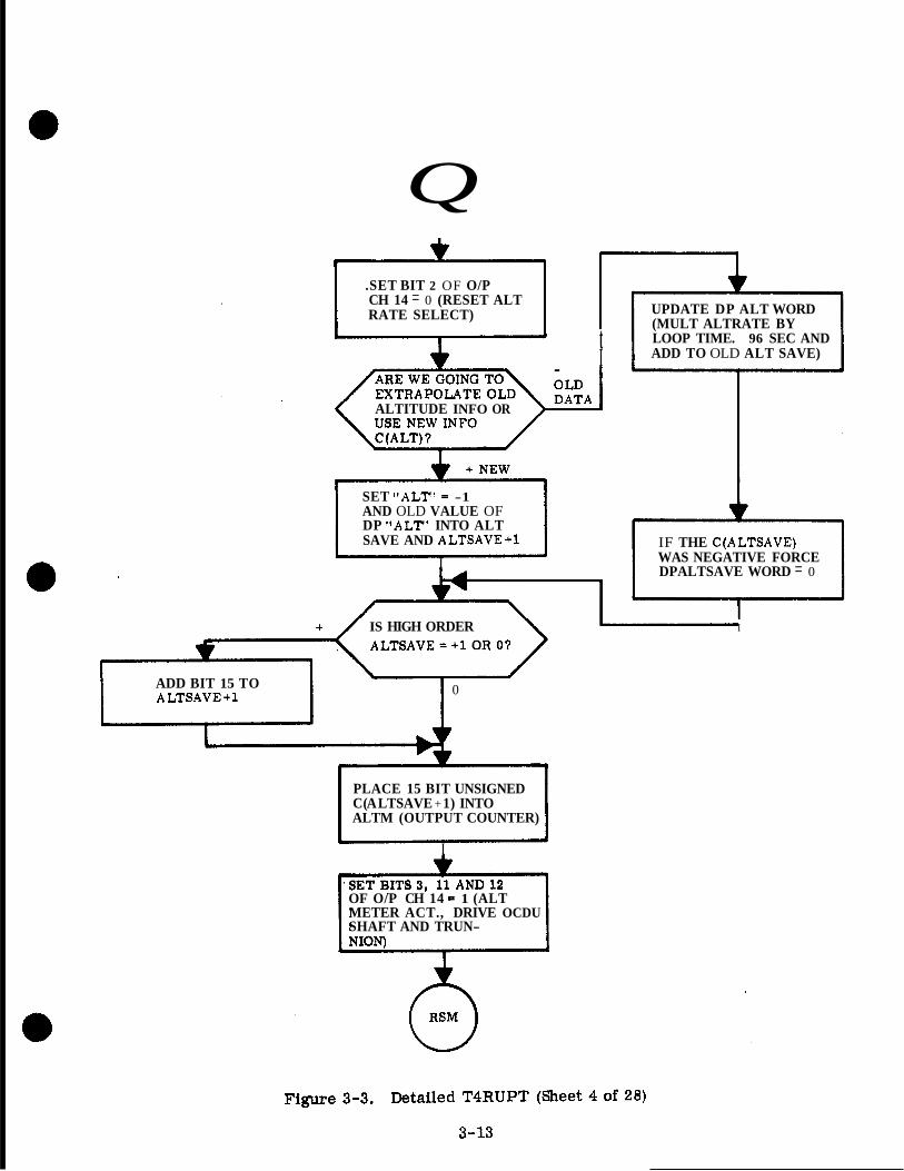
Q .SET BIT 2 OF O/P CH 14 = 0 (RESET ALT RATE SELECT)
I t I
ALTITUDE INFO OR
SET "ALTt = -1 AND OLD VALUE OF DP "ALT' INTO ALT SAVE AND ALTSAVE+l
I
UPDATE DP ALT WORD (MULT ALTRATE BY LOOP TIME. 96 SEC AND ADD TO OLD ALT SAVE)
IF THE C(ALTSAVE) WAS NEGATIVE FORCE DPALTSAVE WORD = 0
+ IS HIGH ORDER I
ADD BIT 15 TO ALTSAVE+l 0
PLACE 15 BIT UNSIGNED C (A LTSAVE + 1) INTO ALTM (OUTPUT COUNTER)
I
OF O/P CH 14 5 1 (ALT METER ACT., DRIVE OCDU SHAFT AND TRUN-

HAS RR AUTO MODE BIT OF CH 33 CHANGED ? (BIT 2)
NO
UPDATE RADMODES
(WT 2 ) I TO PRESENT CONFIG.
MODE JUST GO ON? RADMODES
WAS ANOThdR V 1 PROGRAM USING RR
~ . . L N IT WENT OFF?
BIT 7) / I (STATE BIT 7 )
SET RR TURN-ON AND RR ZERO BITS OF RADMODES (BITS 1 AND 13 = 1)
SCHEDULE TASK "RR TURN-OW' TO BE EXECUTED IN 10 MSEC
( PROGRAM CAUTION 1
A V05 N31 R 1 = 00514 (RADAR GOES OUT OF) AUTO MODE WHILE

UPDATE RADMODES TO REFLECT RRCDU FAIL (RADM0L)ES BIT 7 )
LAMP TEST IN PROGRESS?
(IMODES 33
TRACKER WARNING
I
I WARNING TURNOFFTRACKER I I (DSPTAB+l lD BIT 8 = 0 )
I
0 GIMON
Figure 3-3. Detailed T4RUPT (Sheet 6 of 28)
3-15
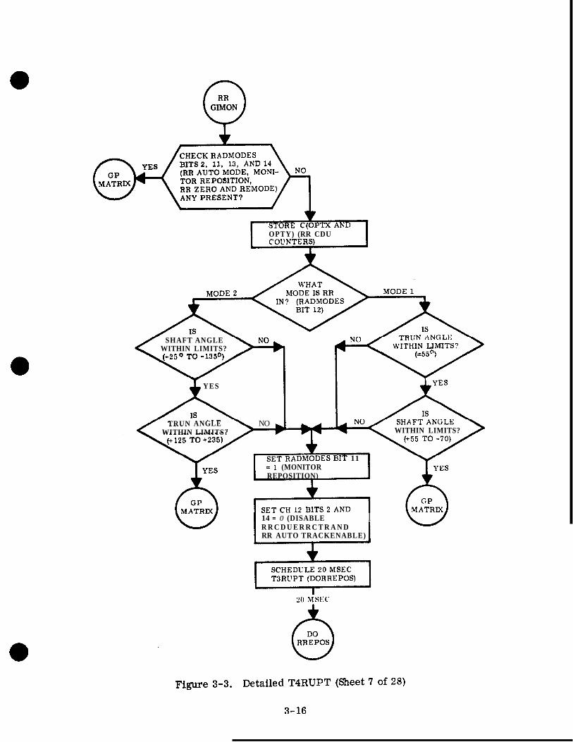
0 GIMON
OPTY) (RR CDU
SHAFT ANGLE WITHIN LIMITS?
YES
WITHIN LIMITS?
6 Y E S
TRUN ANGLE NO WITHIN LIMITS?
)IT 11 = 1 (MONITOR REPOSITION)
1 kES I 14 = 0 (DISABLE I
R R C D U E R R C T R A N D RR AUTO TRACKENABLE)

(-J RR TURN
SET CH 12 BIT 1 = I (ZERO RRCDU)
I SCHEDULE 20 MSEC T3 RU P T I
20 MSEC
SET OPTX AND Y = O
I
SET CH 12 BIT 1 = 0
SCHEDULE 4 SEC T3RUPT
4 SEC w
SET RADMODES BIT 13 = 0
SET RADMODES BIT 12 (RR MODE) .Z 1 OR 0 TO AGREE WITH PRESENT ANT POSITION C(0PTY) IF TRUNNION ANGLE IS > MOO, BIT 12 - 1
Y El
THERE ANY
I SCHEDULE 1 SEC T3RUPT (WAIT 1 SEC I
I BEFORE REMOVING R R TURNON FLAG TO AVOID A POSSIBLE MONITOR REPOSITION ALARM I 0 (REMOVE RR TURNON)
TOUSETHE RR? C(STATE) 6 OVER
I TRACKER WARNING (DSPTAB+llD BIT 8 = 1)
~
Figure 3-3. Detailed T4RUPT (Sheet 8 of 28)
3- 17

0 RREPOS
SET CH 12 BIT 2 = 1 (ENABLE RR CDU ERR C TR)
SET LASTXCMD AND LASTYCMD = 0
PROGRAM CAUTION
SCHEDULE 20 MSEC TBRUPT (DELAY)
REPOSITION
2ND PASS (REMODE)
FOR REPOBITION AND FIRST PA98 OF REMODE REMODE FIRST PASS OR (-180) OR -120° FOR REMODE -60' FOR REMODE SECOND PASS SECOND PASS
1 I - - SET CfRRINDEX) = 0
Figure 3-3. Detailed T4RUPT (Sheet 9 of 28)
3- 18

a Q
a
0
($ (-) NO , YES ARE REMODE AND REPOSITION CMDS PRESENT? (RADMODES
""- "" -1 I I I
\BITS 14 AND'W I f
TERMINATE REPOSITION L , I
I I I I I I I I I
(RADMODES BIT 11 - 0 ) CALC A6 CMD AND SCALE WITH. 59062 I (CALC TRUN ON FIRST PASS AND SHAFT ON SEC PASS) DIFF BETWEEN ACTUAL AND ZERO REF.
TRUN
SET C(0PTXCMD) - 0 SHAFT
I I
I
w CONTROL r
384 PULSES MAX LIMIT CMDS T O
i
CALC DIFF BETWEEN
DESIRED AND S E T INTO LASTCMD AND
APPROPRIATE O P T ( ) CMD (OUTPUT COUNTER)
SET CH 14 BITS 11 AND 12 - 1 (OCDUX AND Y DRIVE)
I
I SCHEDULE 1/2 SEC T3RUPT (RELAY)
I I I I I I I I I I I I
L,"""" J Figure 3-3. Detailed T4RUPT (Sheet 10 of 28)
3-19
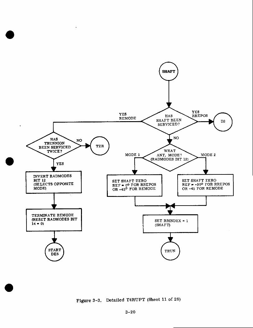
? SHAFT

r """""- I z
BAD REMODE OR
YES BEG DES IS REPOSITION REQUEST PRESENT? (RADMODES BIT 11)
NO
TERMINATE DES (SET RADMODES BIT 10 = 0)
DECREMENT DESCOVNT
(RADMODES BIT 7)
SET INTERNAL FLAG TO INDICATE UNSUC- CESSFUL JOB
PROGRAM CAUTION
I SCHEDULE 1/2 SEC TSRUPT (DELAY)
SET CH 12 BITS 2 AND 14 = 0 (REMOVE RR ECR ENABLE AND RR L"-J
WAKE JOB
REMOVE DESIGNATE
BIT 10) FLAG (RADMODES
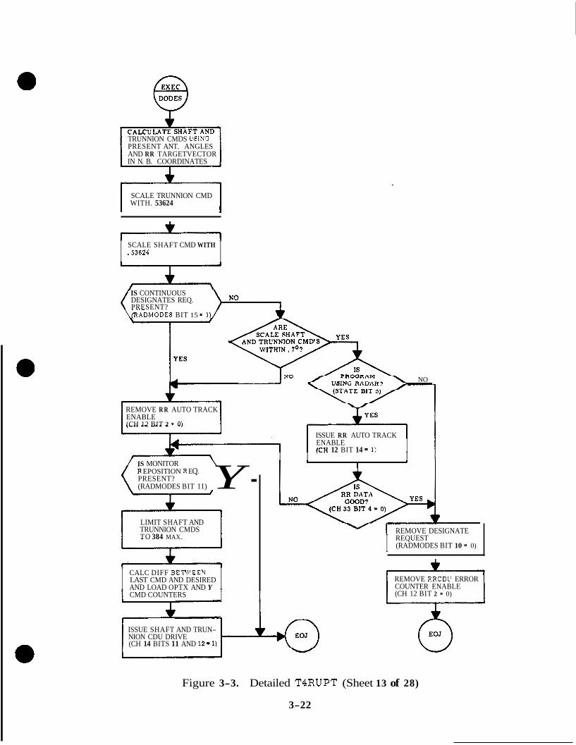
TRUNNION CMDS USING PRESENT ANT. ANGLES AND RR TARGETVECTOR IN N. B. COORDINATES
WITH. 53624 SCALE TRUNNION CMD
I I .53624 SCALE SHAFT CMD WITH
IS CONTINUOUS DESIGNATES REQ. PRESENT?
\%ADMODES BIT 15 = 1)/
A NO
REMOVE R R AUTO TRACK ENABLE (CH 12 BIT 2 - 0 )
ISSUE RR AUTO TRACK &-, I ENABLE (CH 12 BIT 14 = 1) I - I I ' I
/ IS MONITOR \ k EPOSITION R EQ. PRESENT? (RADMODES BIT 11) Y - TRUNNION CMDS LIMIT SHAFT AND
TO 384 MAX.
I CALC DIFF BETWEEN LAST CMD AND DESIRED AND LOAD OPTX AND Y I
REMOVE DESIGNATE
I REQUEST (RADMODES BIT 10 5 0)
CMD COUNTERS I +
ISSUE SHAFT AND TRUN- NION CDU DRIVE (CH 14 BITS 11 AND 12-1)
REMOVE RRCDL' ERROR COUNTER ENABLE (CH 12 BIT 2 - 0)
Figure 3-3. Detailed T4RUPT (Sheet 13 of 28)
3-22
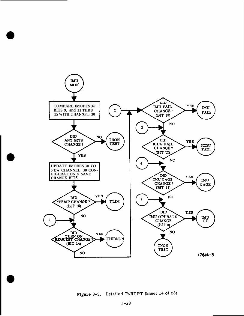
I COMPARE IMODES 30, BITS 9, and 11 THRU 15 WITH CHANNEL 30
UPDATE IMODES 30 TO NEW CHANNEL 30 CON- FIGURATION & SAVE
17614-3

I YES
IS A LAMP NO TEST IN PROCESS?
(IMODES 33, BIT 1 = 1)
I
YES I 1
NO WITHIN LIMITS ? (CH30, BIT 15 = 0 )
TEMP CAUTION (CH11, BIT 4 = 1)
I TURN OFF TEMP CAUTION LAMP. (SET CH11, BIT 4 = 0)
1 L
DID ANY OTHER BITS CHANGE ?
(IMODES 30, BITS 9 AND 11 THRU 14.)
Figure 3-3. Detailed T4RUPT (Sheet 15 of 28)
3-24
I7614 -4

I8 TURN *ON RE-) QUESI’ FAIL
PRESENT ? (IMODES 30,
BIT 2 = I)
YES
*
0 VU5 N31 R1 .- 00207
SS TURN ON RlsQUEST NOT PRESEN’I’ FOR
90 SF4(’)
DID ANY OTHER BITS CllANGE Y
(IMODES 30, BITS 9 AND 11 THRU 13)
17614-5
Figure 3-3. Detailed T4RUPT (Sheet 16 of 28)
3-25

AND IMU FAIL I T B (IMODEII 30, BITtl 10,
TllEIR I N l P l T BITS 12 , AND 13) WIT11
(IMODES 30, DITd I ,
fs8 WARNING (CHl1, BIT 1 7 1 )
TURN OFF ISE WARN-
BIT I = U) I N 0 LAMP (SET CH11,
P I
(&)NO ' (IM01)ES DID ANY 30, OTIlEll BI'CY 0 TEST ,NO(-) DID DIT9 ANY CHANGE OTHER ?
9, 1 1 , AND 12 (IMOOES 30, BITS
9 AND 11)
6 17614-6

ARE WE CAGING? (IMODES 30, BIT
11 = 0)
TERMINATE GYRO AND ICDU DRIVING. (SET CH14, BITS 10, 13,14, AND 15 = 0)
A REMOVE IMU ERROR CNTR ENABLE AND ISS TURN ON DELAY COMPLETED. (SET CH12, BITS 6 AND 15 = 0)
ISSUE COARSE ALIGN ENABLE AND ZERO IMU CDUS. (SET CH12, BITS 4 AND 5 = 1)
NO ATTITUDE
INHIBIT PIPA, ICDU, AND IMU FAILURES AND INDICATE CAGING (SET IMODES 30, BITS
SET CDU (X, Y , AND Z) & GYRO CMD OUTPUT REGISTERS = 0
*
DE-SELECT GYROS (SET CH14, BITS 7 , 8
17614-7
Figure 3-3. Detailed T4RUPT (Sheet 18 of 28)
3-27

Q WAS A PROGRAM
USING THE IMU WHEN TURNED OFF? .c 1 - (STATE, BIT 8 = 1)
REQUEST FAIL PRE- SENT? (IMODES 30, BIT
IS TURN ON
2 = 1)
SET FIRST TURN ON I SAMPLE (IMODES 30,
(PROGRAM,CAUTION)
BIT 7 = 1)-
L
A
17614 -8
Figure 3-3, Detailed TBRUPT (Sheet 19 Of 28)
3-28

IS FIRST TURN ON SAMPLE SET SECOND TURN ON
PRESENT ? (IMODE SAMPLE BIT (SET IMODES 30, BIT 8 = 1) 30, BIT 7 = 11
RESET TC%N ON SAMPLE BITS (SET IMODES 30, BITS 7 AND 8 = 0) -
I YES
IS COARSE ALIGN ENABLE
PRESEST? (CH12, BIT 4 = 1)
IS TYRN ON
AXlODES 30, BIT
\ / (IS PRESEST? nrr O,PEIUTE (IMODES 3
30, BIT 9 = 0)
* 0 PROGR4M CALTION
14 = 0)
S
REAIOVE "IhlT E M O R CSTR ESABLE" .4SD "ISS TYRS OX DELAS
I COI\IPI.ETED. "ISET CH12, BITS 6 AKD 153.0)
ISSUE "COARSE ALIGK ENABLE" A?;D "ZERO IMU CDUS. '' (SET CH12, BITS 4 ASD 5 = 1)
NO ATTITUDE
INHIBIT PIPA, ICDL!, AND M U FAILURES AND MDI- CATE INITLALIZATION (SET MODES 30, BITS 1 AKD 3 TITROUGH 6 = 1)
IS ANOTHER PROGRA hl USIXG
THE IXIU? (STATE, BIT e = 1)
ISHIBIT PIPA. ICDC, .4KD 1 3 C FAILURES AKD I?;DICATE CAGING. (SET IMODES 30. BITS 1 AXD 3 THRP 6 = 1,)
I 1 I ISSUE "ZERO IAW CDUS" (SET CH12, BIT 5 = 1) 1
I I t SCHEDULE TASK "UNi2" TO BE EXECUTED IN 30C hISEC.
SCHEDULE TASK l~ENDTFiON" TO BE EXECUTED IN 90 SEC.
,

SET CDU X, Y AND 2 ' GIMBAL ANGLE COUNTER3 = 0
REMOVE 'COARSE ALIGN ENABLE" AND "ZERO IMU CDUS". SET CH12, B I T S 4 A N D 5 t O
SCHEDULE A 4 SEC DE- LAY FOR COUNTERS TO STABILIZE
I I 4 SEC
REMOVE ICDU A N D IMU FAIL INHIBITS A N D IMTIALIZATION INDICA- TION. (SET IMODES 30, BITS 3 , 4 , AND 6 = 0 )
COMPARE PIPA, ICDU AND IMU FAIL BITS (IMODES 30, BITS 10, 12, AND 13) WITH THEIR INHIBIT BITS (IMODES 30, BITS 1 , 3 AND 4)
IS A LAMP TEST IN PROCESS ?
OMODES 33, BIT 1 = 1) \ /
TURN OFF ISS WARN- ING LAMP (SET CH11, BIT 1 = 0)
REMOVE "ISS TVRN OX DELAY COMPLETED". (SET C H l 2 . BIT 15 = 0)
*
SCHEDULE TASK '' PFAILOK" TO BE EXECUTED IN 10 SEC -
I A
3 IS ANOTHER
TO USE IMU? (STATE BIT 9 * 1) 6 TASK
17614-1 I
Figure 3-3. Detailed T4RUPT (Sheet 21 of 28)
3-30

QUEST FAlL'(8ET RESET TURN ON RE-
IYODES 30 , BIT a = O ) Q
NO
I3 TURN ON IS ANOTHER REQUEST PRESENT PROGRAM WAlTMO
(IMODES 30, TO USE IMU? DELAY SUCCESSFUL? (OLD IMODES 30. BIT 14 = 0) (STATE, BIT 8 = 1)
YES
TURN OFF "NO RESCHEDULE TASK ATTITUDE" "ENDTNON" TO DE INDICATOR EXECUTED M 00 SEC
> J & b I
YES IS I59 4 WARNING I A M P
ON7 (CH11, BIT 1 - 1)
w 4
SET INTERNAL FLAG "0 INDICATE BAD MOUE SWITCH . SET INTERNAL FLAG TO
INDICArE GOOD MODE SWITCH
i
b
Y ES CALLING JOB
SLEEPING?
I WAKE SLEEPING JOB I I No
17614-10
Figure 3-3. Detailed T4RUPT (Sheet 22 of 28)
3-3 1

0 PFAILOK
REMOVE PIPA FAIL INDICATIONS (IMODES 30 BIT 10 AND IMODES 33 BIT 13 = 1) -1
REMOVE CAGING INDICATION (IMODES 30 BIT 5 = 0)
. INSURE ISS WARNING IS O F F (SET CH 11 BIT 1 = 0 )
b
L
Figure 3-3. Detailed T4RUPT (Sheet 23 of 28)
3-32

COMPARE IMODES 33, BITS 11, 12 AND 13 WITH CIMNNEL 33.
NEW C1fANNEL 33 CON- UI’DATE IMODES 33 TO
FIGURATION
17614 -13
Figure 3-3. Detailed TCRUPT (Sheet 24 of 28)
3-33

r I / I 1
I UPDATE RPA FAIL IN IS PIPA FAIL } YES 4 IMODES 30 (SET IMOIWS
UPDATE PIPA FAIL
30, BIT 10 = 1) 13 2 0 ) IMODES 30, BIT 10 = 0 ) ON ? (IMODES 33, BIT IN IMODES 30 (SET
1 J I J
4 I v
COMPARE PIPA, ICDU ANDIMU FAIL DITS (IhIODES 30, DI'I'S LO,
INIUDIT BITS. (MODES 30, BI'I'S 1, 3 AND 4)
12 AND 13) WTII THEIR
UNTNHIHITEU YES
ISS WARNING ( C H I I , BIT 1 = 1)
/ I
IS 'TIIERE A IS IMU OI'EItA'IlNG7 (IMODES 30.
BIT 9 = 0 )
N O
INl'IYAI,IZk~D? (IMODES 30, BITS 5 , 6 , 7 , OH 8 ~ I)
0 PROGRAM CAUTION
VU5 N31
(PIPA FAII. BUT PIPA HI = 00212
I I
17614-14
Figure 3-3. Detailed T4RUPT (Sheet 25 of 28)
3-34

Y NO /-\ TELEMETRY TOO
FAST? (IMODES 33 BIT 12 = 0)
I I YES
PROGRAM CAUTION
R1 = 01105 ( D O W N L I N K TOO
TELEMETRY TOO FAST? (IMODES 33,
BIT 11 = 0)
& GLOCK
I YES
PROGRAM CAUTION
R1 = 01106 (UPLINK TOO FAST)
I 1
DID THE OTHER
33, BIT 11) BIT CHANGE? (IMODES 0 GLOCK
17614- I5
Figure 3-3. Detailed T4RUPT (Sheet 26 of 28)
3-35

IS GIMBAL YES LOCK LAMP Oh' ?
(DSPTAB l l D , BIT 6 = 1)
dNO IT >70° I I TES
A U G N ENABLE
I
( "TAE?TT PROGRESS ? ("ODES
30, BIT 1 = 1)
NO
:S
lNO ISSUE "COARSE ALIGN ENABLE" (SET CH 12, B I T 4 = 1 )
TURX OFF GIMBAL LOCK LAMP (SET DSPTABllD, BIT 6 = 0 )
I / IS GIMBAL \ V F P I
I INHIBIT IMU FAIL (SET IMODES 30 BIT 4 = 1) I
J
I
I
+"-------
I \ BIT 6 = 1) / I
c" ARE WE IKTTIAUZING? (MODES 30, BIT 6 - 1)
G GIMBAL LOCK
1
f i RESUME
17614-16
Figure 3-3. Detailed T4RUPT (Sheet 27 of 28)
3-36

0 MATRIX
CALCULATE THE TERMS FOR THE GIMBAL TO PILOT (GP) AND THE PILOT TO GIMBAL (PG) MATRIX. CALCULATE:
1. 2. 3. 4. 5. 6. 7. 8.
SIN (MG\ COS (MG) SIN (OG) -SIN (OG) COS (MG) -SIN ( O G ) / COS (MG) COS (OG) COS (OG) COS (MG) COS (OG) / COS (MG)
Figure 3-3. Detailed T4RUPT (Sheet 28 of 28)
3-37
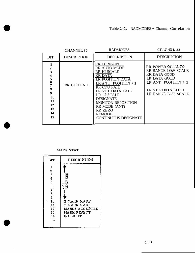
a
BIT
1 2 3 4 5 6 7 8 9 10 11 12 13 14 15
CHANNEL 30 ~~~ ~
DESCRIPTION
RR CDU FAIL
Table 3-2. RADMODES - Channel Correlation
RADMODES CIANNEL 33
DESCRIPTION
RR TURN-ON RR AUTO MODE RR HI SCALE RR DATA LR POSITION DATA LR ANT. POSITION # 2 RR CDU FAIL LR VEL DATA FAIL LR KI SCALE DESIGNATE MONITOR REPOSITION RR MODE (ANT) RR ZERO REMODE CONTINUOUS DESIGNATE
DESCRIPTION
RR POWER ON/AUTO RR RANGE LOW SCALE RR DATA GOOD LR DATA GOOD LR ANT. POSITION # 1
LR VEL DATA GOOD LR RANGE LOW SCALE
MARK STAT

Table 3-3. IMODES 30 - Channel 30 Correlation
- Bit
1 2 3 4 5 6 7 8 9
10
11
12
13
14
15
-
-
IMODES 30
Description PIPA FAIL INHIBIT (ISS WARNING) TURN ON REQUEST FAIL ICDU FAIL INHIBIT IMU FAIL INHIBIT PIPA FAIL INHIBIT (PROG. CAUTION) IMU BEING INITIALIZED ISS INITIALIZATION REQUEST ISS INITIALIZATION WAIT 1 SAMPLE IMU OPERATING PIPA FAIL IMU CAGE ICDU FAIL IMU FAIL ISS TURN ON REQUEST ISS TEMP IN LIMITS
r Bit
9
11
12
13 14
15
Description
IMU OPERATE
IMU CAGE
ICDU FAIL IMU FAIL ISS TURN Oh' REQUEST ISS TEMP IN LIMITS
Table 3-4. IMODES 33 - Channel 33 Correlation
IMODES 33 I Channel 33 (Inverted Logic) I Bit Bit Description
1 GYRO SCALE FACTOR TEST 2 LAMP TEST IN PROGRESS
11
13 PIPA FAIL 13
12 DOWNLINK TOO FAST 12
11 UPLINK TOO FAST
Description
UPLINK TOO FAST DOWNLINK TOO FAST PIPA FAIL
3-39

3 .2 DOWNTELEMETRY ROUTINE (DNRUPT)
The Downtelemetry Program is used to select the appropriate computer words to be trans- mitted via the Downlink Telemetry System and setting the selected words into channels 34 and 35.
The overall synchronization of the downlink is obtained from the external telemetry pro- grammer. In order to understand the sequence of events occurring during this program, one must know terminology and control pulse rates. The following is a synopsis of terms and data required for a discussion of this program:
Telemetry Word = 8 bits Two telemetry words = 1 computer word 1 Prime Frame = 128 telmetry words 5 Telemetry Words = 1 DP Computer Data Word
*BIT RATE = 51.2 KC or 1 . 6 KC
*TL START PULSE = 50 pps or 10 pps
*TL END = 50 pps or 10 pps *NOTE: The two rates given are basic rates, the lower of which is
used to transmit data when the spacecraft is located a con- siderable distance from the ground tracking station. Our discussion will be based on the higher of the two rates.
The telemetry system transmits data to the ground at the rate of 50 frames per sec. A frame consists of 128 eight bit telemetry words, five of which are allotted for computer data. Thus, every 20 msec computer data is sent out (figure 3-4). At the high rate 50 D P computer words a re transmitted each second, with some single precision words grouped together and sent two at a time as double precision pairs,
If one considers the five telemetry words (figure 3-5) to be repeated 50 times per second and each transmission to contain different data, one would have a picture of what the down telemetry program must accomplish. A general format is shown in figure 3-6.
The nominal downlink list for Sunburst, Rev 14 is provided as figure 3-7.
The downrupt flow diagram is shown in figure 3-8. The arrival of the TELEND pulse will cause the program interrupt service to route control of the computer to the DNRUPT routine. Each pass through the DNRUPT routine will load output channels 34 and 35 with the next two words to be outputed via the telemetry system. These two words will picked from these channels upon occurrence of the next TELSTART pulse. The FRESHSTART/ RESTART routine initializes the contents of DNTMGOTO to the starting address of DNPHASE 1 so that the first TELEND pulse will cause a DNRUPT which will transfer the control of the computer to the routine defined as DNPHASE 1.
3-40

BIT RATE 61.2 KC
1 . 6 KC
120 5 12 0 3 5 WORDS WORDS WORDS WORDS WORDS WORDS
i t- 1 FRAME 128 WORDS
20 MSEC/FRAME -i 17561
The arrival of the TLEND pulse forces a DNRUPT which transfers control to the DODOWNTM program. This program loads the next double-precision data scheduled to be sent down into channels 34 and 35, and sets bit 7 of channel 13 (Word Order Bit) to a ZERO for transmission of the other 49 D P words of the 50 DP word format. Channel 13, bit 7 , controls the logical state of the leading bit (word order bit) in each 40 bit transmission so that the first 40 bit word transmitted is distinct from the remaining 49. Bits 2-33 consist of the contents of channels 34 and 35; bits 34-40 are all zeros. a
Figure 3-4. Computer Interface with Telemetry
3-41
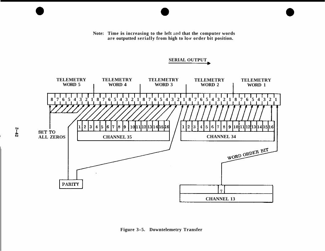
Note: Time is increasing to the left nnd that the computer words are outputted serially from high to loiv order bit position.
SERIAL OUTPUT - TELEMETRY TELEMETRY TELEMETRY TELEMETRY TELEMETRY
WORD 5 WORD 4 WORD 3 WORD 2 WORD 1
8 7 6 5 4 3 2 1 8 7 6 5 4 3 2 1 8 7 6 5 4 3 2 1 8 7 6 5 4 3 2 1 8 7 6 5 4 3 2 1
ALL ZEROS CHANNEL 35 1 CHANNEL 34 J
CHANNEL 13 -
Figure 3-5. Downtelemetry Transfer

WORD #1
2
'I 39 40- 41 42 43 44 45 46
48 49 50
47 -
-
LAST 7 BITS
0000000
0000000
0000000
0000000
CHANNEL 35
00437,
3810 COMPUTER WORDS DEFINED BY DATA LIST
DSPTAB+l DSPTAB+3 DSPTAB +5 DSPTAB +7 DSPTAB +9 DSPTAB+llD TIME 1 CHANNEL 12 CHANNEL 14 CHANNEL 31 CHANNEL 33 R E P E A T
CHANNEL 34 LIST START
ooooo ( ADDRESS
3810 COMPUTER WORDS DEFINED BY DATA LIST
DSPTAB DSPTAB+2 DSPTAB+4 DSPTAB +6 DSPTAB+8 DSPTAB+lOD TIME 2 CHANNEL 11 CHANNEL 13 CHANNEL 30 CHANNEL 32
WORD ORDER
BIT ~-
0 1 1 1 1 1 1 1 1 1 1 1 1 1 1 1 1 1 1 1 1 1 1 1 1 1 1 1
Figure 3-6. Downtelemetry General Computer Format
3-43

DNPHS 1 1 2
DNPHS X AND 3 DNPHS 2 FROM SNAPSHOT BUFFER 4
5
6
7
8 9
10
11 12
13
DNPHS 3 14 15
16
17
18 19 20
21 22
23
24 25
CHANNEL 34 CHANNEL 35 ,
ooooo (LIST ADDRESS) 004378 PIPA X
XYMARK MARKSTAT DELVX THETAD+ 2
THETAD+ 1 THETAD
TANG+ 1 TANG LASTXCMD LASTYCMD LMP CMD +1 LMPCMD FA I LR EG REDOCTR
STATE+ 3 STATE+ 2
STATE + 1 STATE
OPT X OPT Y
OPT Y CDU Z CDU Y CDU X
LATVEL FOHVEL
FINALT+ 1 FINA LT ALTSAVE + 1 A LTSAVE
FMALT ALTRATE
A L T + I A LT '
TIMEHOLDc 1 TIMEHOLD OPTWOLD+ 1 OPTYHOLD
SAMPISUM+ 1 SAM PLSUM
DESCOUNT OLDATAGD
SAM P LIM RADMODES
RHCP PIPA Z PIPA Y
L
.
,
- 1
I
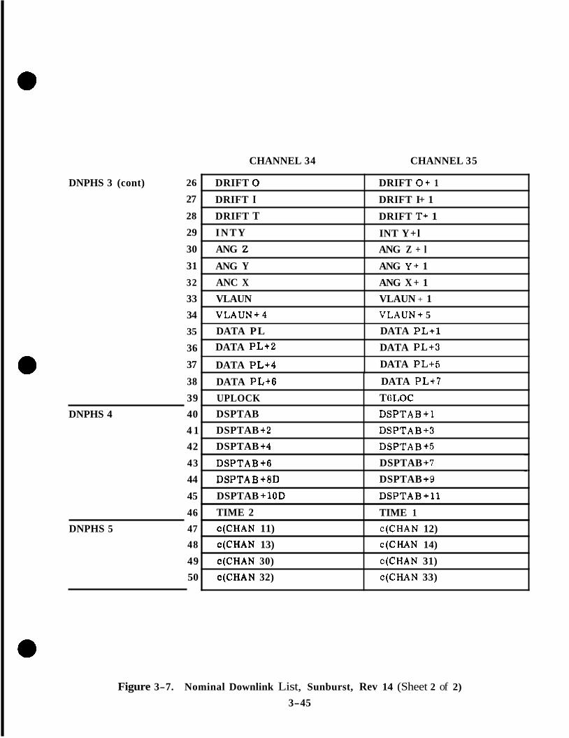
DNPHS 3 (cont)
CHANNEL 34 CHANNEL 35
26
T ti LOC UPLOCK 39
DATA PL+7 DATA PL+6 38
DATA PL+5 DATA PL+4 37
DATA PL+3 DATA PL+2 36
DATA PL+1 DATA PL 35
VLAUN+ 5 VLAUN+4 34 VLAUN + 1 VLAUN 33 ANG X + 1 ANC X 32
ANG Y + 1 ANG Y 31 ANG Z + l ANG Z 30 INT Y+l I N T Y 29 DRIFT T+ 1 DRIFT T 28
DRIFT I+ 1 DRIFT I 27 DRIFT O + 1 DRIFT 0
DNPHS 4 40
DSPTAB+5 DSPTAB +4 42 DSPTAB+3 DSPTAB +2 4 1 DSPTAB+l DSPTAB
TIME 1 TIME 2 46
DSPTAB+11 DSPTAB +10D 45
DSPTAB +9 DSPTAB+BD 44 DSPTAB +7 DSPTAB+6 43
- w
DNPHS 5 47
c(CHAN 33) c(CHAN 32) 50 c(CHAN 31) c(CHAN 30) 49 c(CHAN 14) c(CHAN 13) 48 c(CHAN 12) c(CHAN 11)
Figure 3-7. Nominal Downlink List, Sunburst, Rev 14 (Sheet 2 of 2)
3-45
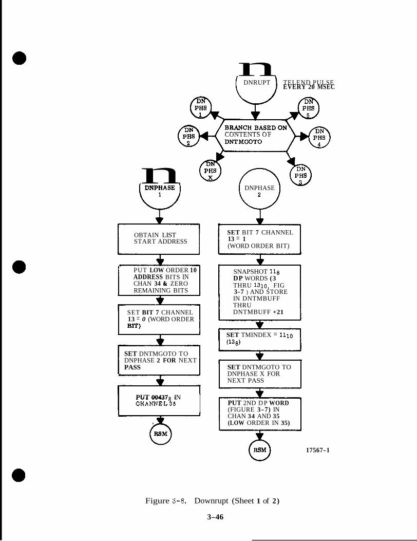
n [ DNRUPT ) TELEND PULSE EVERY 20 MSEC
CONTENTS O F
n DNPHASE ii DNPHASE
OBTAIN LIST START ADDRESS
<
. PUT LOW ORDER 10 ADDRESS BITS IN CHAN 34 & ZERO REMAINING BITS
*
SET BIT 7 CHANNEL 13 = 0 (WORD ORDER BIT) -
SET DNTMGOTO TO DNPHASE 2 FOR NEXT PASS .
PUT 00437 IN CHANNEL^ I
SET BIT 7 CHANNEL 13 = 1 (WORD ORDER BIT)
SNAPSHOT 118 DP WORDS (3 THRU 1310, FIG
IN DNTMBUFF THRU DNTMBUFF +21
3-7 ) AND STORE
SET TMINDEX = 1110 (138)
cc SET DNTMGOTO TO DNPHASE X FOR NEXT PASS
~ ~ ~~~ ~
PUT 2ND D P WORD
CHAN 34 AND 35 (LOW ORDER IN 35)
(FIGURE 3-7) IN
@ 17567-1
Figure 3-8. Downrupt (Sheet 1 of 2)
3-46

Figure 3-8. Downrupt (Sheet 2 c i 2)
3-47
DNPHASE 1 - DNPHASE 1 will set the ID word into channels 34 and 35. This ID word is composed of the downlink list starting address in channel 34 and octal 00437 in channel 35. DNPHASE 1 will also set the word order bit to zero to indicate that the word in channels 34 and 35 is the ID word. DNTMGOTO is set up S O that the next DNRUPT wil l transfer control to DNPHASE 2.
DNPHASE 2 - DNPHASE 2 sets the word order bit to 1 to indicate that the contents of channels 34 and 35 is ID WORD. DNTMGOTO is set to route computer control to DNPHASE X on the next DNRUPT. DP words 3 through 13 a r e obtained and stored in buffer registers and DP word 2 is inserted into channels 34 and 35. The words stored in the buffer will be loaded into channels 34 and 35 by the next eleven DNRUPT routines. They are sampled and stored at this time so that when interpreted on the ground they can be compared to each other with reference to the same time frame.
DNPHASE X - DNPHASE X merely obtains the next sequential snapshot word and puts it in channels 34 and 35 to be plucked upon receipt of the next TELSTART pulse.
DNPHASE 3 - DNPHASE 3 sets up DNTMGOTO for DNPHASE 4 on the next DNRUPT and sets the first DP DSPTAB word in channels 34 and 35.
DNPHASE 4 - DNPHASE 4 sets the remaining DSPTABS, TIME 2 , and TIME 1 and channels 11 and 12 into channels 34 and 35.
DNPHASE 5 - DNPHASE 5 sets the remaining words of the downlink list into channels 34 and 35 i n the following order: channels 13 and 14; channels 30 and 31; and channels 32 and 33. The next entry into DNPHASE 5 will route control of the computer to DNPHASE 1 to begin the second transmission of the downlink list.
3 . 3 KEYBOARD AND UPLINK TELEMETRY INPUT PROCESSING PROGRAM
The keyboard and uplink telemetry processing program includes the KEYRUPT routine, the UPRUPT routine and the routines of the PINBALL program. The KEYRLTPT and UPRUPT routines accept the input keycodes from the keyboard and uplink telemetry system. The PINBALL program assebles the accepted inputs into meaningful information and controls the execution of that which is indicated by the assembled information. Besides performing the functions mentioned above, the PINBALL program can be used by internal programs to perform the various functions which can be performed through keyboard o r uplink inputs.
The KEYRUPT and UPRUPT routines operate under control of the program interrupt circuit- ry of the computer and the processing specified by them is initiated whenever the appropriate input is present, The PINBALL program is executed under control of the Executive program and is scheduled by the KEYRUPT or UPRUPT routines to process the keycodes that they accept. When an internal program uses the PINBALL program, i t is processed under the scheduling of the internal proqram using one or more of its routines.
Basically, the PINBALL program is made up of a group of routines with a routine for each of the types of keys on the DSKY's. There is a NUM, NOUN, VERB, CLEAR, SIGN, ERROR RESET, KEYRELEASE, and an ENTER routine. In addition to these routines, there a re numerous other routines which control is transferred to by the ENTER routine which perform the requested action.
3-48

Figure 3-9 is a general flow diagram for the PINBALL program and the related KEYRUPT and UPRUPT routines. Inputs a re accepted by the KEYRUPT routine from the computers DSKY o r by the UPRUPT routine from a ground based keyboard via the uplink telemetry system. Both of these routines accept the keycode input and schedule the CHARIN (CHARAC- TER INPUT) routine of the PINBALL program to be executed through the Executive routine.
Because of the relatively high priority assigned to the Job CHARIN, the processsing of the input keycode begins quickly. CHARIN routes control to the proper routine depending on the keycode input. If the NOUN key is depressed, control is routed to the NOUN routine, etc. After the processing required for a keycode input is completed, control is routed to the Executive End Job routine to terminate the PINBALL program. When another key is de- pressed, the KEYRUPT or UPRUPT routine schedules CHARIN which routes control to the proper routine, the processing is performed and the PINBALL job is terminated. This sequence continues until the required information has been loaded. When the final ENTER key is depressed, this sequence occurs again except that the ENTER routine routes control to another routine which performs the specified action. When the processing required is completed, control is routed to the Executive End of Job routine.
The internal programs of the computer supply the appropriate information to the ENTER routine and can thereby utilize any of the routines which are used a s a result of keyboard o r uplink inputs. Prior to transferring control to the ENTER routine to utilize one o r more of the routines accessible through the ENTER routine, the internal program must make sure that there is not another internal program or that the astronaut is not using the PINBALL program. If the PINBALL program is already in use, control is returned to the internal program. What is accomplished then is up to the internal program but, in most cases, the internal program is put to sleep until the PINBALL routine is available for its use.
3 . 3 . 1 DSKY AND UPLINK INTERRUPT OPERATION. The keyboard and uplink telemetry interrupt processing program includes the KEYRUPT and the UPRUPT rou- tines. These routines process the keycodes which will be used by CHARIN. The KEY- RUPT and UPRUPT routines accept the input keycodes from the keyboard and uplink telemetry system. PINBALL assembles the accepted inputs into meaningful information and controls the execution of that which is indicated by the assembled information. The KEYRUPT and UPRUPT routines operate under control of the computer and processing specified by them is initiated whenever the appropriate input is present.
The KEYRUPT and UPRUPT routines accept input keycodes from the DSKY keyboard o r from a ground based keyboard, respectively. The KEYRUPT routine obtains the five bit keycode from input channel 15 register bits 1 through 5 (MAIN DSKY) or input channel 16 bits 1 through 5 (NAV DSKY). The UPRUPT routine obtains the keycode information from the INLINK counter of the computer memory. The information obtained from the INLINK counter consists of 16 bits of data, shown in figure 3-10, which has been re- ceived serially and manipulated into parallel form. Of the 16 bits of information, 15 bits a re used for three copies of the keycode being transmitted. Bits 15 through 11 (high 5) and 5 through 1 (low 5 ) contain the keycode, while bits 10 through 6 (middle 5) contain the complement of the keycode. The 16th bit is always a binary 1 and is used to indicate, through the computer's program interrupt circuitry, that the complete 16 bits of informa- tion have been received.
3-49

CONDITIOKS NUM TOCONVERTNEXT FIVE NUMERICAL
WHAT TYPE OF ENTRY HAS BEEN
BJUTES CONTROL MADE, THIS ROUTINE
To ROUTIh'Is WHICH ENABLE THE VARIOUS ACTIONS To BE DONE AS SPECIFIED BY THE VERB
DECIMAL To
SIGN IN PROPER BINARY: DISPLAY
REGISTER R1, :7 t ERROR RESET
INDICATORS. RESETS FAILURE
TELEMETRY UNBLOCK.5 PP
RELEASF5 DSRY
c- I. f, L BY VERB
17513
W
Figure 3-9. General Flow Diagram for Pinball
3-50
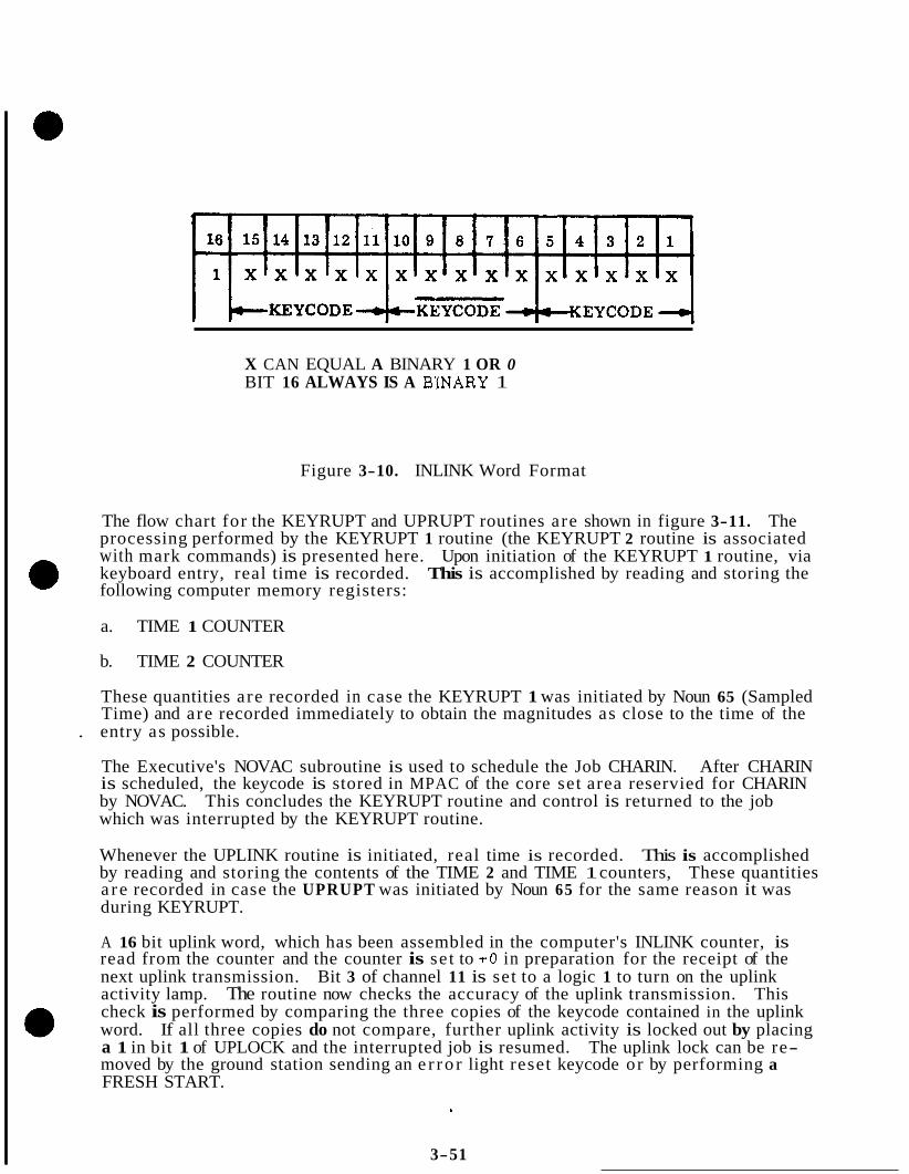
X CAN EQUAL A BINARY 1 OR 0 BIT 16 ALWAYS IS A BINARY 1
Figure 3-10. INLINK Word Format
The flow chart for the KEYRUPT and UPRUPT routines are shown in figure 3-11. The processing performed by the KEYRUPT 1 routine (the KEYRUPT 2 routine is associated with mark commands) is presented here. Upon initiation of the KEYRUPT 1 routine, via keyboard entry, real time is recorded. This is accomplished by reading and storing the following computer memory registers:
a. TIME 1 COUNTER
b. TIME 2 COUNTER
These quantities are recorded in case the KEYRUPT 1 was initiated by Noun 65 (Sampled Time) and are recorded immediately to obtain the magnitudes as close to the time of the
. entry as possible.
The Executive's NOVAC subroutine is used to schedule the Job CHARIN. After CHARIN is scheduled, the keycode is stored in MPAC of the core set area reservied for CHARIN by NOVAC. This concludes the KEYRUPT routine and control is returned to the job which was interrupted by the KEYRUPT routine.
Whenever the UPLINK routine is initiated, real time is recorded. This is accomplished by reading and storing the contents of the TIME 2 and TIME 1 counters, These quantities a r e recorded in case the UPRUPT was initiated by Noun 65 for the same reason it was during KEYRUPT.
A 16 bit uplink word, which has been assembled in the computer's INLINK counter, is read from the counter and the counter is set to + O in preparation for the receipt of the next uplink transmission. Bit 3 of channel 11 is set to a logic 1 to turn on the uplink activity lamp. The routine now checks the accuracy of the uplink transmission. This check is performed by comparing the three copies of the keycode contained in the uplink word. If all three copies do not compare, further uplink activity is locked out by placing a 1 in bit 1 of UPLOCK and the interrupted job is resumed. The uplink lock can be re- moved by the ground station sending an e r ro r light reset keycode or by performing a FRESH START.
3-51

READ & STORE CONTENTS OF TTME 2 & TIME 1
STORE CONTENTS OF INLINK COUNTER & SET IT TO +O
CH 11, BIT 3 = 1)
TEST TRIPLE CHARACTER I REDUNDANCY
A
STORE "0" IN BIT ,1 OFUPLOCKTO ACCEPT UPLINK DATA
4 YES
READ & STORE CONTENTS OF TIME 2 & TIME 1
SAVE KEYCODE
SCHEDULE JOB CHARIN WITH PRIORITY 30 VIA EXECUTIVE NOVAC
STORE KEYCODE IN MPAC OF CORE SET AREA RESERVED FOR CHARIN
I
SET BIT 1 OF UPLOCK TO I' 1" TO LOCK OUT FURTHER UPLINK ACTIVITY UNTIL ERROR LIGHT RESET IS SENT VIA UPLINK
c- : 17576
Figure 3-11. KEYRUPT and UPRUPT
3-52

If the uplink transmission is good, a check is made to determine if an e r r o r light reset keycode was transmitted. The 5 bit e r r o r light reset keycode is 10010. This keycode is the same as the operator e r r o r keycode of the DSKY and will perform the same func- tions. If the uplink word is e r r o r light reset, a 0 is placed in bit 1 of Qplock to remove the uplink lock if the lock was in use.
The Executive's NOVAC subroutine is now used to schedule the Job CHARIN. After CHARIN is scheduled, the keycode is stored in MPAC of the core set area reserved for CHARIN by NOVAC and the interrupted job is resumed.
If the uplink transmission is good and the keycode is not e r r o r light reset , a check is made to determine if the uplink activity is locked out. If the uplink activity is locked out, the interrupted job is resumed. If the uplink data is not locked out, the CHARIN subroutine is scheduled a s before by NOVAC and the keycode i s inserted into the reserved core set area a s previously noted. The interrupted job is resumed.
3 . 3 . 2 THE PINBALL PROGRAM. The PINBALL program a s previously stated per- forms the functions of assembling information a s it is entered through the keyboard of uplink telemetry system. It also initiates the proper function as indicated by the key- board o r uplink inputs. This program is divided into various subroutines which a re presented in the following paragraphs.
3.3 .2 . 1 CHARIN. CHARIN performs a routing function to other subroutines of the PINBALL program. The routing performed by CHARIN is based on the keycode input received by the computer from either the DSKY keyboard o r the uplink telemetry system. CHARIN is scheduled to be performed by either the KEYRUPT or UPRUPT routines when a keycode is accepted by these routines, and is performed under control of the Executive routine a s shown in figure 3-12.
When the Executive routine determines that the CHARIN is the highest priority job scheduled, control is routed to the CHARIN job. The processing performed by the job is shown by the flow diagram in figure 3-12. Upon initiation of the processing for CHARIN, an interlock is set up by the computer on itself so that no other programs can use the DSKY. In other words, the use of the DSKY is reserved for the PINBALL pro- gram and the astronaut or a ground based keyboard operator.
Control is routed to the CHARIN subroutine dependent on the keycode input. For instance, if a numerical keycode has been entered, control is routed to the NUM routine, If the NOUN keycode is entered, control is routed to the NOUN routine, etc. If the keycode input is illegal, control is route? to the CHARALRM subroutine.
3 .3 .2 .2 NOUN Subroutine. Control is routed to the NOUN subroutine of CHARIN whenever the input keycode is that of the NOUN key.
The following is performed by this subroutine:
a. The NOUN REG, a memory register used to store the assembled NOUN code, is set to zero in preparation for the receipt of a new NOUN code.
b. The NUM subroutine, which will assemble the new NOUN code as it is entered, is conditioned to accept the next two keycodes a s a NOUN code.
3-53

0 CHAR-
. SET UP INTERLOCK 4 SO NO OTHER INTERNAL CALLING PROGRAM CAN USE THE DSKY's
10000 .= 0 10001 = VERB 00001 = 1 10010 = ERROR RESET 00010 = 2 11001 = KEY RELEASE 00011 = 3 11010 = + 00100 = 4 11011 = - 00101 = 5 11100 = ENTER 00110 = 6 11110 = CLEAR 00111 - 7 11111 = NOUN 01000 = 8 01001 = 9
OTHER 14 CODES ARE ILLEGAL
Figure 3-12. CHARIN (Sheet 1 of 11)
3-54
17514-1

SET NOUNREG T O +O (NOUNREG IS AN INTERNAL REGISTER WHICH CONTAINS THE LAST NOUN USED)
CONDITION NUM SUB- ROUTINE TO ACCEPT A NOUN CODE
S E T VERBREG TO + O (VERBREG IS AN INTERNAL REGISTER WHICH CONTAINS THE LAST VERB USED)
CONDITION NUM SUB- ROUTINE TO ACCEPT A VERB CODE.
I
BLANK THE DSKY
(SET OCTAL 73777 (SET OCTAL 73777 VERB DISPLAYS NOUN DISPLAYS BLANK THE DSKY
INTO DSPTAB+ 8D) INTO DSPTABf9D) i
I
INCREMENT NOUT - I
.
CONDITION N U M ROUTINE TOACCEPTANOCTAL ENTRY
6 E. 0. J. 17514-2 Figure 3-12, CHARIN (Sheet 2 of 11)
3-55
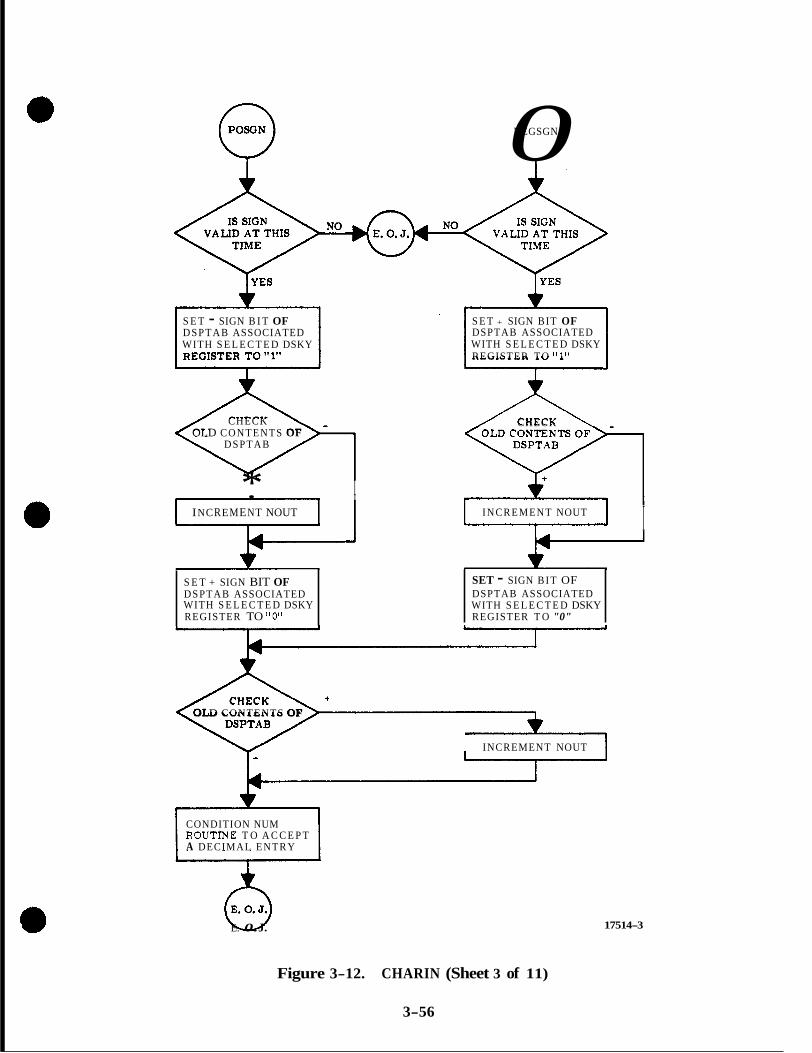
0 NEGSGN
S E T - SIGN B I T OF DSPTAB ASSOCIATED WITH S E L E C T E D DSKY
S E T + SIGN BIT OF DSPTAB ASSOCIATED WITH S E L E C T E D DSKY REGISTER T O "1"
CHECK OLD CONTENTS OF
DSPTAB
* I . I
INCREMENT NOUT
S E T + SIGN BIT OF DSPTAB ASSOCIATED WITH S E L E C T E D DSKY REGISTER TO "0"
A CHECK
INCREMENT NOUT 1 I
SET - SIGN B I T OF DSPTAB ASSOCIATED WITH S E L E C T E D DSKY REGISTER T O "0"
OLD CONTENTS OF '
INCREMENT NOUT
CONDITION NUM R O U T h E T O A C C E P T A DECIMAL ENTRY
6 E. 0. J.
Figure 3-12. CHARIN (Sheet 3 of 11)
3-56
17514-3

0 KEYCODE LOADED 8 OR 9 KEYCODE LOADED
1 , 2 , 3 , 4 . 5 . 6 . OR 7 KEYCODE LOADED
THE 8UBROUTINE I8 CONDITIONED T O USE +O MSTEAD b4 O F THE ZERO K E Y W D E
YES
EXTRA CHARACTER
SET APPROPRIATE DSPTAB TO PROPER CONFIGURATION FOR DIGIT BEING LOADED.
INCREMENT OLD CONTENTS OF CHECK
DSPTAB
I SHXFT WORDBEMC I ~.."
L E F T 0 ADD NEW
SHIFTED WORD CHARACTERTO
FORMED s PLACES I
DECIMAL
INPUT TO BINARY AND STORE IN APPROPRIATE INPUT BUFFER (XREG. YREG, OR ZREG).
c(BUFFER) BY 1010
NUMERAL] AND ADD NEW
[MULTIPLY OLD
T ,
SCALE THE DOUBLE PRECISION ENTRY WORD BY MULTIPLING IT B Y 214/105 (. 16384 IN DECIMAL)
COMPLEMENT DOUBLE PRECISION WORDS TO OBTAIN THE NEGATIVE MAGNITUDE
* W
Figure 3-12, CHARIN (Sheet 4 of 11)
3-57
17514-4
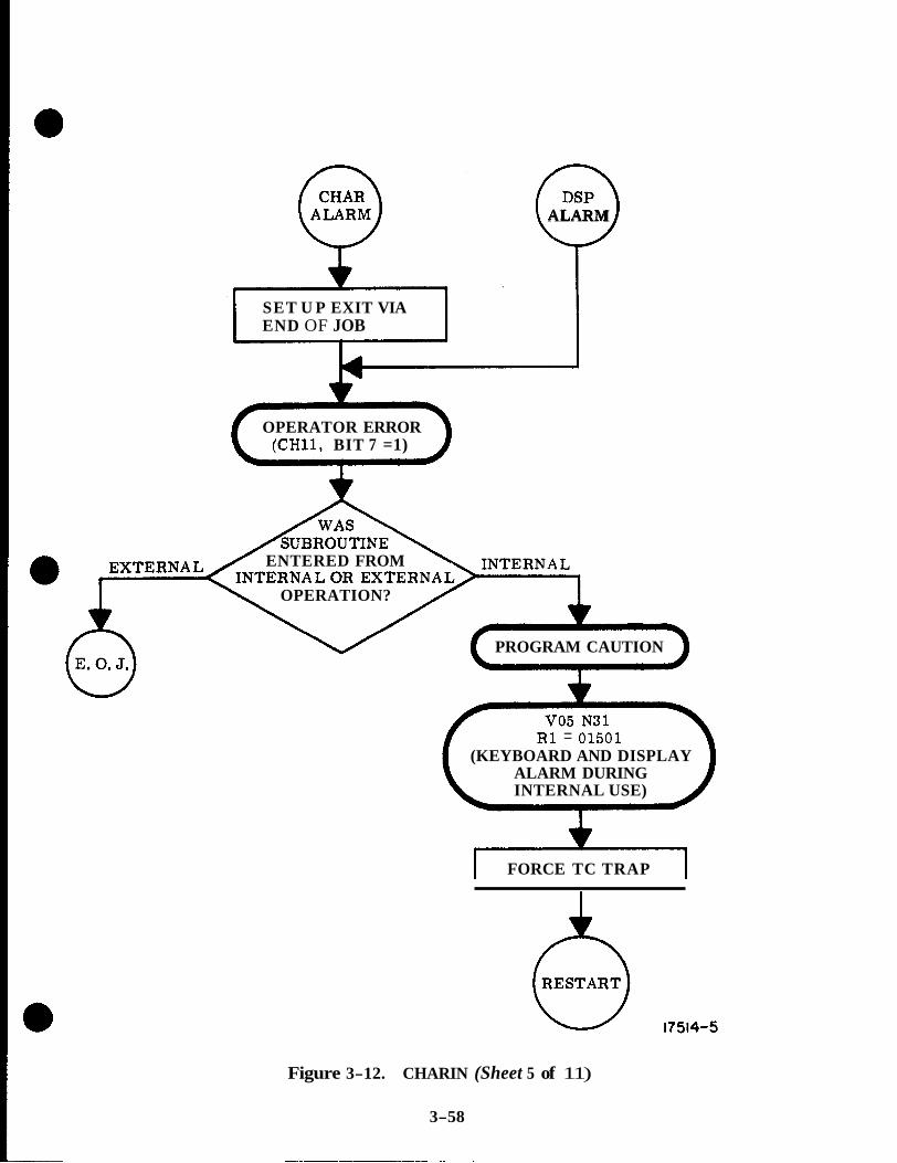
SET U P EXIT VIA END OF JOB
OPERATOR ERROR (CH11, BIT 7 =1)
i' ALARM
ENTERED FROM
OPERATION?
PROGRAM CAUTION
R1 = 01501 (KEYBOARD AND DISPLAY
ALARM DURING INTERNAL USE)
I FORCE TC TRAP 1
Figure 3-12. CHARIN (Sheet 5 of 11)
3-58
~~~~~~~~~~ ~~ ~
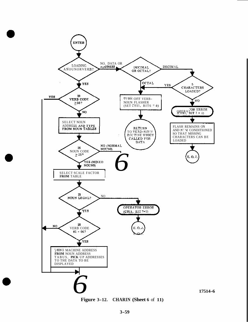
Q ENTER
LOADING A N O U N O R V E R B ?
NO, DATA OR
T Q R PnnF \ " I TLTRN OFF VERB- I
SELECT NOUN ADDRESS AND TYPE
I NOUN FLASHER (SET CH11, B I T 6 = 0 )
:OR ERROR I f OPERA? .
NOUN CODE
I I SELECT SCALE FACTOR FROM TABLE I
TO VERB-NOL'N ROVTINE \VHICF!
6 f
NO
OPERATOR ERROR (CH11, RIT 7 = 1 )
VERB CODE
USlNG MACHINE ADDRESS
T A B U S , PICK U P ADDRESSES FROM NOUN ADDRESS
T O THE DATA TO BE DISPLAYED
6 Figure 3-12. CHARIN (Sheet 6 of 11)
3-59
FLASH REMAINS ON AND NI'W CONDITIONED SO THAT MISSING CHARACTERS CAN B E LOADED
~ ~~~
0 E. 0. J.
6 E. 0. J .
17514-6

'?
VB52 PLEASE XARK Y VB51 PLEASE MAEK.
VB53PLEASEZrURKXORY
-5 AUGK TJXE VB54 PULSE TOROL'E GYROS
VB56 PERFORM BANIKSL7.l -7 PERFORM SYSTEM TESTS YBM) PREPARE FOR STAhVBY VES1 RECOVER FRO% STANDBY TB62 SCAN IM INBITS
VBi3 RHC USED FGR MlPL MP. vBl4 RHC USED FOR RATE CMD.
VB76 DAP NARRC?X DEADBAND 9
VI375 DAP " D E DEADBAND
ma m m m E AGS
NOT INCLVDED IN SLWBl?tST REV 14 LISTIsG
IcHl1. BIT 7-11
SET ILLEGAL VERB
EXTVJACT. BIT 3 = 0 FL4G BY SETIWG I
E.O.J.
17514-7
Figure 3-12. CHARIN (Sheet 7 of 11)
3-60
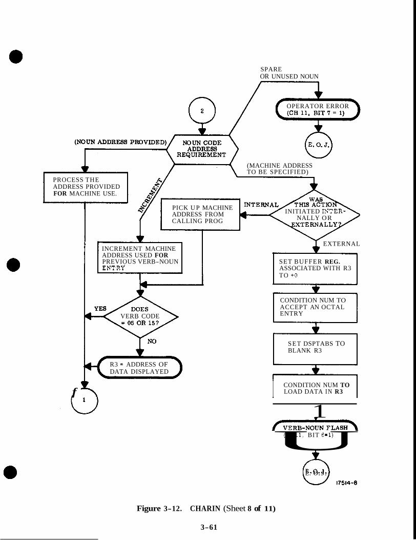
SPARE OR UNUSED NOUN
I
f
OPERATOR ERROR
(MACHINE ADDRESS TO BE SPECIFIED)
PROCESS THE ADDRESS PROVIDED FOR MACHINE USE.
PICK U P MACHINE ADDRESS FROM CALLING PROG
INITIATED INTER- NALLY OR
INCREMENT MACHINE ADDRESS USED FOR PREVIOUS VERB-NOUN SET BUFFER REG.
EXTERNAL
ENTRY ASSOCIATED WITH R3 TO +O
CONDITION NUM TO ACCEPT AN OCTAL ENTRY VERB CODE
SET DSPTABS TO BLANK R3
R3 = ADDRESS OF DATA DISPLAYED
I CONDITION NUM TO LOAD DATA IN R3
1
U (CH11, BIT 6=1)
h E. 0. J. 17514-8
Figure 3-12. CHARIN (Sheet 8 of 11)
3-61

L
FREE WKY 80 INTERNAL PROGRAM CAN UBE THE D8KY
. RESET CAUTION INDICATORS (SET CH11, BIT 10 - 1)
RESET D S P T A B l l D WITH THE EXCEPTION OF BITB 4 AND (I (NO ATTITUDE AND GIMBAL LOCK WHICH A R E LEFT INTACT
RESET TELEMETRY TOO FAST & PIPA FAIL (SET IMODES 33, BITS 11, 12 AND 13 - 1 )
. RESET PIPA FAIL. BIT IN IMODES 30 (SET IMODES 30, BIT 10 - 1)
> I I I > I
RESET RADAR FAIL BITS IN RADMO1)ES
RESET TEST ALARM. (SET C1113, BIT 10 - 0)
TURN OFF UPLINK ACTIVITY 0 OPERATOIt ERROR LAMPS. (YET CH11, BITS 3 AND 7 - 0)
I
SELECT DlBPWY TABLE (DBPTAB) TU BE CHECKED .
ENSURE PROPER D8pTAB BIT 12 FORMAT
HAVE ALL DISPLAY TABLES FROM
I BET FAJLREa I BFAJLTO + O , 1
Figure 3-12. CHARIN (Sheet 9 of 11)
3-62

0 VBRELDSP
TURN OFF UPLINK ACTIVITY LAMP (SET CH11, BIT 3 = 0 )
b WAKE UP SLEEPING JOB WAITING TO USE
LIST HAVE AN DSKY (EXECUTIVE'S JOB WAKE SUBROUTINE)
RESERVE INKY FOR USE BY THE AWAKENED JOB
D
1 NO I
TURNOFF THEKEY RELEASE LAMP (SET CH11, BIT 5 = 0 )
RELEASE INTERLOCK BET UP BY OPERATOR USE OR UPLINK USE OF DSKY
v
17514-10
Figure 3-12. CHARIN (Sheet 10 of 11)
3-63

:: CLEAR
* SELECT RELATIVE ADDRESS FOR CLEARING SPECIFIED BUFFER REGISTERS & DSPTABS
YES A FIRST SINCE CLEAR LAST NO
r DECREMENT THE VERB
I 1
SET BUFFER REGISTERS ASSOCIATED WITH THE DBKY REGISTER BEING USED TO + O
*
. CONDITION NUM TO ACCEPT AN OCTAL ENTRY
i
2
SET DSPTABS TO BLANK THE SELECTED DSKY REGISTER
,
CONDITION NUM TO LOAD DATA IN THE DSKY REGISTER JUST CLEARED
I
6 E. 0. J.
Figure 3-12. CHARIN (Sheet 11 of 11)
3-64
17514-11
c. The display table, DSPTAB+8D, i s set to octal 73777 to blank the two NOUN display panels.
d. The NUM subroutine is conditioned to accept octal keycode entries.
After performing these functions, control is routed to the Executive End Job routine.
3 .3 .2 .3 VERB Subroutine. The VERB Subroutine is similar to the NOUN Routine, Control is routed to this subroutine whenever a VERB keycode is received.
The following functions a re performed by this routine:
a. The VERB REG, a memory register used to store the VERB code, is set to zero in preparation for the receifl of a new VERB code.
b. The NUM subroutine is conditioned to accept the next two numerical inputs as a VERB code.
c. The display table, DSPTAB+SD, is set to octal 73777 to blank the VERB display panels.
a d. The NUM subroutine is conditioned to accept octal keycode entries.
After performing these functions, control is routed to the Executive End Job sub- routine.
3.3 .2 . 4 SIGN Subroutine. Control is routed to the SIGN subroutine of CHARIN if the keycode is for either the + or - key.
The processing performed by the POSGN (positive sign) is listed below:
a. A check is made to determine if a SIGN is valid at this time in the sequence of keycode entries. If it is not, control is routed to the End Job subroutine of the Executive. If the SIGN is valid, which it would be prior to entering a piece of decimal data, the processing proceeds.
b. The - sign bit (bit 11) of the selected DSPTAB (display table) is set to 1. The DSPTAB is using inverted loglc so the above action will reset the - sign bit.
c. The + sign bit @it 11) of the selected DSPTAB is set to 0. Since the DSPTAB uses inverted logic, this action sets the + sign bit.
NOTE: Different DSPTAB registers contain the + sign bit and the - sign bit for the DSPTAB's used to provide displays in R1, R2 and R3 of the DSKY. The result of the above operation is that the + sign will be displayed in the appropriate DSKY register.
d. The NUM routine is conditioned to accept decimal keycode entries.
After performing these functions, control is routed to the End Job subroutine of the Executive.
3-65
The processing performed by the NEGSGN (negative sign) subroutine is essentially the same a s the POSGN subroutines. The differences are that the + SIGN bit is set to 1, the - SIGN bit is set to 0 which will result in the negative sign being lighted on the selected DSKY register.
3 . 3 . 2 . 5 NUM Subroutine. The NUM Subroutine is used whenever a numerical keycode is received. This routine provides for the assembly of the numerical information a s it is entered into the computer. Control over the type of data (either decimal o r octal) that is to be entered and the number of characters to accept is established by the NOUN, VERB and SIGN subroutines. The NOUN and VERB subroutines condition the NUM subroutine to accept two octal characters while the SIGN subroutine conditions the NUM subroutine to accept a five decimal Characters. If a word is to be entered in octal, the sign keys are not used prior to entering the characters of the word and the NUM subroutine assumes that the data is being entered in octal. In the assembly process, the information being entered is converted from octal or decimal to a natural binary form,
The processing performed by the NUM routine is as follows:
If CHARIN is provided with a zero (10000) keycode, control is routed to NUM-2 prior to the keycode being processed by NUM. NUM-2 converts the zero keycode to + O for use by NUM.
If CHARIN is provided with an 8 or 9 keycode, control is routed to 89TEST. The 89TEST will determine if digit 8 o r 9 is valid at this time.
NOTE: If the NUM subroutine had been conditioned to accept an octal input and one of these two numerical characters are used, an operator e r ro r exists since these digits do not exist in the octal numbering system. Control is then transferred to the CHARALRM subroutine. The OPERATOR ERROR indicator will be lighted. Then control is routed to the End Job sub- routine. If the keycode entered is not an 8 or 9 for octal loads or if decimal data is being loaded, processing proceeds.
A check is made to determine if all of the required characters have been entered for the information being loaded. In the case of entering VERB and NOUN codes, the required number of characters is two while five are required for either octal o r decimal data word entries. If all of the required characters have been processed, control is routed to the End Job subroutine and the character input is not utilized. However, when all of the required characters have not been entered, processing proceeds.
The correct display table (DSPTAB) location is selected corresponding to the numerical entry being processed, and this DSPTAB is set to the proper configura- tion to light the digit being loaded on the DSKY.
If an octal load is being made, all previously assembled information for this load is shifted three digit positions toward the most significant digit position. Then the newly received keycode input is added to the shifted word with the keycode in the least significant digits. By shifting the previously assembled portion of a quantity being loaded in octal, the magnitude of the previously assembled information is increased by a 'factor of eight. A s the information is keyed in most significant octal digit first, the information is assembled and "converted" to a natural binary form.
3-66

If the information is being entered in decimal, a similar procedure is followed, With decimal loads, all previously assembled information for a particular quantity is shifted three digit positions toward the most significant digit position and the same quantity shifted one digit position towards the most significant digit posi- tions. These two quantities are added. This increases the magnitude of the previ- ously assembled information by a factor of 10. After forming the sum of the two shifted quantities, the newly entered keycode is added to this sum.
If a decimal load is being made, all previously assembled information is multi- plied by 10 (Decimal) and the newly received keycode is added. The result is the natural binary equivalent of the present decimal entry and is stored in the buffer register corresponding to the DSKY register (R l , R2 o r R3) being loaded.
In either case, octal o r decimal loading, after the assembly and conversion proce- dure outlined above is completed, a check is made to determine if the required number of input characters have been provided. If not, control is routed to the End Job subroutine.
If the required number of characters have been entered, a check is made to deter- mine if the load is octal o r decimal. If the information loaded was octal, control is routed to the End Job subroutine.
If the load was decimal, the information loaded is scaled by a factor of 0. 16384 and a check is made to determine if the decimal data is negative or positive. If the quantity loaded is negative, the words of the load are complemented putting them in negative form. If the load was positive, the information is used in its uncomplemented or positive form. In either caae, control is then routed to the End Job subroutine.
3 . 3 . 2 . 6 CHARALRM Subroutine. The CHARALRM subroutine is used whenever an illegal 5 bit keycode is processed by PINBALL'S subroutines. The following is performed:
a. Bit 7 of channel 11 is set to 1 to turn on the operator e r r o r lamp on the DSJSY. The operator e r r o r lamp flashes.
b, A check is made to determine if the illegal keycode resulted from an external input such as uplink telemetry o r the DSKY keyboard. If the keycode originally was an external input, control is transferred to the EXECUTIVE'S End of Job Sub- routine.
c. If the keycode originated internal to the computer, control is transferred to the ABORT Routine which will result in the Program Caution lamp being lighted, Verb 05, Noun 31 being displayed and 01501 being in R1.
d. The program abort sets the computer operation into a TC Trap condition which will force a restart.
3 . 3 . 2 . 7 ENTER Subroutine. Control is routed to the ENTER subroutine when the keycode for the ENTER key is received. Internal programs also use the capabili- ties provided by the routines accessible through the ENTER subroutine.
3-67

In the procedure of entering the VERB and NOUN codes, the ENTER key is used. When it is used in this instance, the ENTER subroutine performs a routing function to a particular routine specified by the VERB code. Also, if it is applicable, the ENTER subroutine selects a machine address to be used by the routine specified by the VERB code using the NOUN code. When the ENTER key is used after load- ing a five character data word, the ENTER subroutine returns control to the routine which requested that data be loaded.
The processing performed is as follows:
a. A check is made to determine if the ENTER is for a NOUN-VERB. If it is not, the ENTER must have been a result of a data or address load. In this case, the flashing of the VERB-NOUN display panels is occurring a8 set by this routine o r the routine which requested the load. A check is made to determine if the data o r address entry was made in octal or decimal. If the entry was in decimal, an additional check is made to insure that five characters were entered. If the entry was octal or five decimal characters, the noun-verb flasher is turned off and con- trol is returned to the caller. If a decimal entry was initiated but five characters were not entered, the OPERATOR ERROR lamp on the DSKY is lighted. The noun- verb flasher will remain on and the NUM subroutine is conditioned to accept the missing characters. Control is routed to the End of Job subroutine.
b. If the load was that of a VERB-NOUN code, a check is made to determine if the VERB code is equal to or greater than octal 30. If it is, control is routed to connecting point #l. If the VERB code is less than 30, the processing proceeds by selecting the nouns machine address and type from applicable tables.
c. If the NOUN code is equal to o r greater than 55, the scale factors associated with that NOUN are selected from applicable tables. A check is made to determine i f the NOUN is legal. If the NOUN is not legal, the OPERATOR ERROR lamp is lighted and control is routed to the End of Job subroutine. Then a check is made to determine if the VERB code is 1 through 6. If it is, the machine address from the Noun Address Table is used to obtain the address of the data to be displayed, Whether the VERB code is 1 through 6 or not, control is routed to connecting point #l. If the NOUN code is less than 55, control is routed to a check which deter- mines the NOUN address requirement.
d. The NOUN code is checked to determine if the NOUN machine address is pro- vided, if the previous NOUN'S machine address should be incremented, if the NOUN is a spare or unused NOUN or i f the machine address is to be specified.
e . If a specified machine address is required, a check is made to determine whe- ther the entry to the ENTER subroutine was due to external (keyboard or uplink) action. If the entry was from an internal source, the address is picked up from the calling routine. If the entry was from an external source, the buffer registers associated with R3 of the DSKY are set to +O and the NUM subroutine is conditioned to accept an octal entry. The display tables (DSPTAB's) are set to blank R3 of the DSKY. The NUM subroutine is now conditioned to load data into R3 and the NOUN- VERB flasher is turned on.
f. If a spare or unused noun code is used, the OPERATOR ERROR lamp is lighted and control is routed to the End of Job subroutine.
3-68

g. If the noun code address is provided, the address is processed for use in the operation specified by the VERB code.
h. If the noun code requirement calls for the previous address to be incremented, the incrementation is performed on the machine address used for the previous NOUN-VERB entry.
i. If the machine address is picked up from the calling routine or if the machine address of the previous NOUN-VERB entry was incremented, the VERB code is checked to determine if it is 05 or 15. If these are used, control is routed to connecting point #l. If not, the display tables (DSPTAB's) a re set so that the T4RUPT routine will display the machine address of the data displayed in R1 in R3. Control is then routed to connecting point #l.
j. From connecting point #1, control is routed to a check on the VERB code. If the VERB code is less than 40, the VERB code is used to route control to the appropriate VERB routine. These routines essentially provide for the display, monitor and load of data.
k. If the VERB code is greater than o r equal to 40, a check is made to determine if a job is waiting to use the DSKY. If it is , 'the waiting job is activated using the Job Wake subroutine. Then, an internal/DSKY interlock is set so that no other internal program or job can use the DSKY other than the job just awakened. Then, the KEY RELEASE indicator is turned off if it was illuminated. The operator/DSKY interlock is removed to allow the internal programs to use the DSKY. The VERB code is used to route control to the appropriate VERB route.
3 . 3 . 2 . 8 Error Reset Subroutine. Whenever the ERROR RESET key is depressed on the DSKY o r the keycode is received via the uplink telemetry system, CHARIN routes control to the ERROR RESET routine, to turn off e r ro r lamps and forces bit 12 of all DSPTAB's to proper configuration,
After the display tables a re checked, FAILREG (FAILURE NUMBER REGISTER) and SFAIL (SELF CHECK FAILURE REGISTER) a re set to zero.
3 . 3 . 2 . 9 Key Release Subroutine, The KEY RELEASE subroutine (VBRELDSP) is processed whenever the key is depressed on the DSKY or the keycode is received via the uplink telemetry system. This key is used after completing an entry to the computer and releases the operator/DSKY interlock. This enables an internal pro- gram to utilize the DSKY.
3 .3 .2 .10 Clear Subroutine. CHARIN transfers control to the CLEAR subroutine whenever it receives a keycode for CLEAR from the DSKY or uplink telemetry system. This subroutine tfclearsff the register R1, R2, o r R3 of the DSKY which is presently being loaded. Successive depressions of the CLEAR key cause the previously loaded registers to be ffclearedff. This enables the correction of erroneously entered data but is effective only if used prior to using the last ENTER in a sequence of entering data. Beside clearing the DSKY registers, the memory registers used to assemble and store the information within the computer a re also cleared. Neither verbs nor nouns can be cleared by the clear subroutine.
3-69
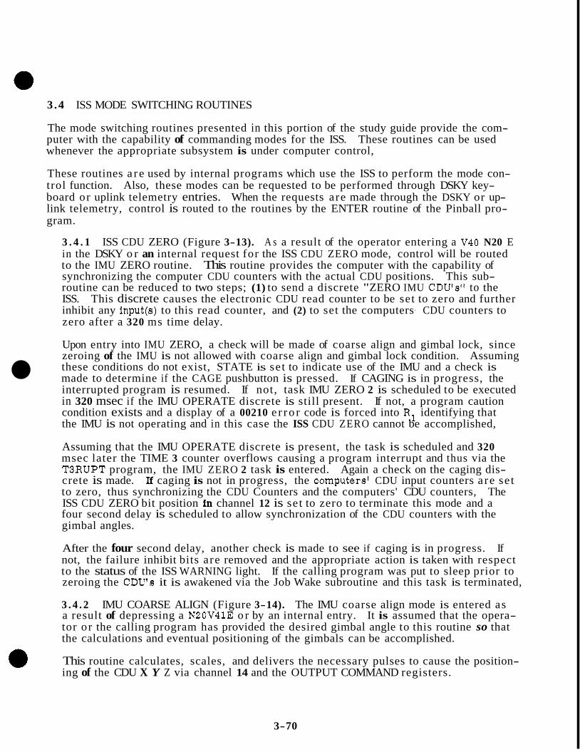
3 .4 ISS MODE SWITCHING ROUTINES
The mode switching routines presented in this portion of the study guide provide the com- puter with the capability of commanding modes for the ISS. These routines can be used whenever the appropriate subsystem is under computer control,
These routines a r e used by internal programs which use the ISS to perform the mode con- trol function. Also, these modes can be requested to be performed through DSKY key- board or uplink telemetry entries. When the requests are made through the DSKY or up- link telemetry, control is routed to the routines by the ENTER routine of the Pinball pro- gram.
3 . 4 . 1 ISS CDU ZERO (Figure 3-13). A s a result of the operator entering a V40 N20 E in the DSKY o r an internal request for the ISS CDU ZERO mode, control will be routed to the IMU ZERO routine. This routine provides the computer with the capability of synchronizing the computer CDU counters with the actual CDU positions. This sub- routine can be reduced to two steps; (1) to send a discrete "ZERO IMU CDUfsff to the ISS. This discrete causes the electronic CDU read counter to be set to zero and further inhibit any input(s) to this read counter, and (2) to set the computersf CDU counters to zero after a 320 ms time delay.
Upon entry into IMU ZERO, a check will be made of coarse align and gimbal lock, since zeroing of the IMU is not allowed with coarse align and gimbal lock condition. Assuming
made to determine if the CAGE pushbutton is pressed. If CAGING is in progress, the interrupted program is resumed. If not, task IMU ZERO 2 is scheduled to be executed in 320 msec if the IMU OPERATE discrete is still present. If not, a program caution condition exists and a display of a 00210 e r ro r code is forced into R1 identifying that the IMU is not operating and in this case the ISS CDU ZERO cannot be accomplished,
these conditions do not exist, STATE is set to indicate use of the IMU and a check is
Assuming that the IMU OPERATE discrete is present, the task is scheduled and 320 msec later the TIME 3 counter overflows causing a program interrupt and thus via the T3RUPT program, the IMU ZERO 2 task is entered. Again a check on the caging dis- crete is made. I€ caging is not in progress, the computers' CDU input counters a re se t to zero, thus synchronizing the CDU Counters and the computers' CDU counters, The ISS CDU ZERO bit position in channel 12 is set to zero to terminate this mode and a four second delay is scheduled to allow synchronization of the CDU counters with the gimbal angles.
After the four second delay, another check is made to see if caging is in progress. If not, the failure inhibit bits are removed and the appropriate action is taken with respect to the status of the ISS WARNING light. If the calling program was put to sleep prior to zeroing the CDU's it is awakened via the Job Wake subroutine and this task is terminated,
3 . 4 . 2 IMU COARSE ALIGN (Figure 3-14). The IMU coarse align mode is entered as a result of depressing a N20V41E or by an internal entry. It is assumed that the opera- tor or the calling program has provided the desired gimbal angle to this routine so that the calculations and eventual positioning of the gimbals can be accomplished.
This routine calculates, scales, and delivers the necessary pulses to cause the position- ing of the CDU X Y Z via channel 14 and the OUTPUT COMMAND registers.
3-70
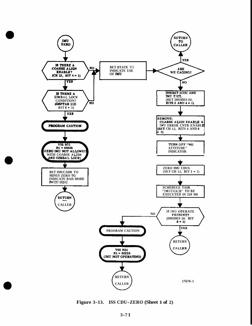
BET BTATE TO INDICATE USE OF M U -
OIMBAL U X K CONDITION? (DBPTAB 11D
BIT 0 - 1)
< PROORAM CAUTION
R1 = 00208
WITH COARSE ALION
BET IMUCADR TO MINUS ZERO TO INDICATE BAD MODE SWITCIiING
CALLER
W
IMU FAIL (BET IMODES 90,
IMU ERROR CNTR ENABL CH 12, BITS 4 AND 6 I
ATTITUDE" INDICATOR
ZERO IMU CDUS. (SET CH 12, BIT 6 = 1)
I SCHEDULE TASK "IMUZER(32" TO BE EXECUTED IN 320 MS
I8 IMU OPERATE
(IMODES 30. BIT NO
PROORAM CAUTION
0 VOS N31
(IMU NOT OPERATINO) R 1 - 00210
RETURN
CALLER
RETURN
CA LLRR
17670-1
Figure 3-13. ISS CDU-ZERO (Sheet 1 of 2)
3-7 1
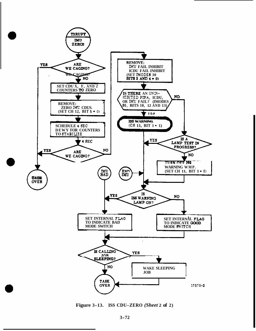
=?e WE CAGING?
w SET CDU X, Y , A N D Z COUNTERS ZERO
I 1 REMOVE:
(SET CH 12, BIT 5 - 0 ) ZERO IMU CDUS.
I SCHEDULE 4 SEC DEWY FOR COUNTERS TO STABIUZE 1
e 1 3 OVER
REMOVE: IMU FAIL INHIBIT ICDU FAIL INHIBIT
(SET IMODEB 30 BITt33AND4-0)
s TI~ERE AN u ~ m - HIBITED P P A , ICDU, OR IMU FAIL? (IMODES
, BITS 10, 12 AND 13)
IS9 WARNING (CH 11, BIT 1 - 1)
1
WARNING W M P . (SET CH 11, BIT 1 - 0 )
rn
SET INTERNAL F W G SET INTERNAL FLAG TO INDICATE BAD TO INDICATE GOOD MODE SWITCH MODE SWITCB .
I 1
I
7 SLEEPING?
WAKE SLEEPING I JOB I w-1 17670-2
Figure 3-13. ISS CDU-ZERO (Sheet 2 of 2)
3-72
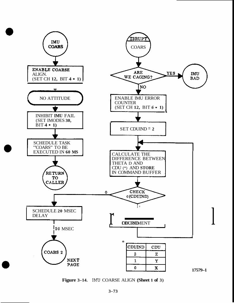
0 COARS
ALIGN. (SET CH 12, BIT 4 - 1)
f NO ATTITUDE 3 . 7
INHIBIT IMU FAIL (SET IMODES 30, BIT 4 = 1)
L
SCHEDULE TASK "COARS" TO BE EXECUTED IN 60 MS
COARS
ENABLE IMU ERROR COUNTER (SET CH 12, BIT 6 = 1) .
. SET CDUIND = 2
i
CALCULATE THE DIFFERENCE BETWEEN THETA D AND CDU (*) AND STORE IN COMMAND BUFFER
I
I I + SCHEDULE 20 MSEC DE LAY
120 MSEC r - l DECREMENT CDUIND
I * ml
X 17579-1
Figure 3-14. IMU COARSE ALIGN (Sheet 1 of 3)
3-73

(COARS 2 ) t -600 MS I SCHEDULE 600 MS DELAY
SET CDUIND = 2 I I
DESIRED CDU ANGLE POS, NEG OR ZERO? (CALL
REDUCE CONTENTS O F PROPER COMMAND
MANn I COMMAND
SET he INTO PROPER REDUCE CONTENTS OF COMMAND REGISTER PROPER COMMAND
BUFFER BY MAX COM- BUFFER BY MAX
SET MAX ALLOWABLE SET PROPER COMMAND SET MAX ALLOWABLE
REGISTER (19210) REGISTER INTO PROPER COMMAND BUFFER TO ZERO INTO PROPER COMMAND
(-19210)
0 SET PROPER COMMAND REGISTER TO ZERO
DECREMENT CDUIND
NO YES
c SCHEDULE 1 .5 SEC DE LAY TO ALLOW GIMBALS TO SETTLE
DRIVE CDUX, Y AND 2. (SET CH 14, BITS 13, 14, AND 15 = 1)
I i
17579-2
Figure 3-14. M U COARSE ALIGN (Sheet 2 of 3)
3-74

0 COARS
CDU ACTUAL - I THETAD = A9’
ANGLES?
SET GYRO COMPENSATION REGISTERS TO ZERO IN
PENSATION PREPARATION FOR COM-
T +
(=7 PROGRAM CAUTION
R1 = 00211 (COARSE ALIGN
17579-3
Figure 3-14. IMU COARSE ALIGN (Sheet 3 of 3)
3-75

After entering the IMU coarse align routine, the coarse align enable discrete is sent to the ISS. This discrete results in the mode switch to coarse align. The IMU Failure INHIBIT is placed in I MODES 30 because during coarse align an IMU failure could OCCLW during the expected high drive rates. A task lfCOARS1l is scheduled via the waitlist to be executed in 60 msec. This allows time for the mode switching to take place.
In 60 msec the TIME 3 counter overflows and the "COARS' task is started.
A check is made to see if the CAGE switch is energized. If so, the task is terminated, Assuming that caging is not in progress, the IMU e r ro r counter is enabled and a cyclic counter called the CDUIND (CDU indicator) is initialized to 2. This counter identifies the specific CDU which is being operated on. If the c(CDU1ND) is +2 calculations are on the CDUZ if the c(CDU1ND) = +1 the CDUY is operated on and if '0, the CDUX. No- tice each time a calculation on a specific CDU angle is performed, the CDUIND is decremented to set the routing control to select the next CDU, After calculating the last A @ (difference Angle) a 20 msec wait is entered. This insures that the last calculation is complete.
Again a check on CAGING is accomplished. Assume caging is not in progress, the CDUIND is initialized for a limiting check on all three CDU's. The magnitude of the maximum allowable output pulses is f 192 per 600 msec. This limiting insures that the ECDU will not saturate. If the number of pulses required is less than the maximum allowable, then the actual number of pulses is put into the COMMAND register, If the number of required pulses is greater than the maximum allowable, the maximum allow- able is placed into the COMMAND register and any remaining pulses will be evaluated and sent in 600 msec. After all three CDU COMMAND registers have been loaded, a check is made to see if pulses are to be sent.
If there a re pulses to be sent, bits 13, 14 and 15 of channel 14 are set = 1 causing driv- ing of all three ECDU channels at once. 600 msec is allowed to send out the pulses prior to going through the loop again.
If there a re no pulses to be sent (as will be the case when coarse align is completed) a 1 .5 sec settle time is provided.
Since the pulsing requirements for coarse align are completed, a check is now made on the status of the CAGE switch. Assuming no caging, a check is made to see if the coarse alignment of the IMU was accomplished to within 20 about all three axes. If not, a program caution condition exists and the e r ro r code 00211 is displayed (coarse align e r ror ) and the program caution light is illuminated.
*X, however, all axes check to within 20, the gyro compensation registers are initial- ized in preparation for the gyro compensation routine.
3 . 4 . 3 IMU FINE ALIGN (Figure 3-15). The Fine Align mode is entered by either an internal program request or by entering a V42E via the DSKY. (It should be recalled that in the Fine Align mode of operation, the CDU's repeat the gimbal position. )
Assuming that CAGING is not in progress, bits 4 and 6 of channel 12 are set to zero
seconds and the second IMUFINED in 90 seconds. and two tasks are scheduled. The first llIFAILOK!l is scheduled to be executed in 5
3-76
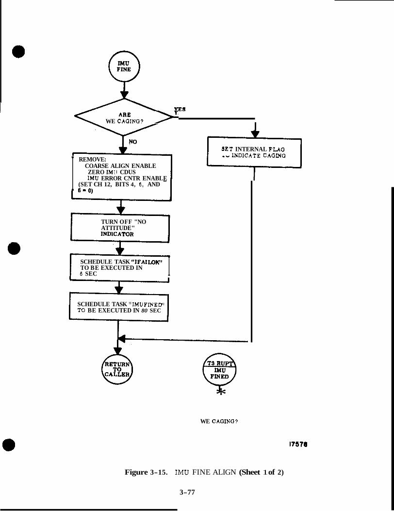
A "E8
WE CAQINO? ARE F SET INTERNAL FLAG
'"DICATE CAOINO
I REMOVE: COARSE ALIGN ENABLE
ZERO IMll CDUS IMU ERROR CNTR ENABLE
(SET CH 12, BITS 4, 5 , AND a * n\ 1 ""VI - 1
TURN OFF "NO ATTITUDE"
SCHEDULE TASK "IFAII.DICt TO BE EXECUTED IN I 6 SEC I
SCHEDULE TASK "IMUFINED' TO BE EXECUTED IN 80 SEC
* WE CAGING?
I7578
Figure 3-15. IMU FINE ALIGN (Sheet 1 of 2)
3-77

9- 1 FAILOK
ARE WE INITIALIZING ? IMODES 30, BIT 6=1
(&) IS ENABLE COARSE PRESENT ALIGN ? YES (CH12, BIT 4-1)
RESET IMU FAIL INHIBIT (1MODES 30, BIT 4=0)
b
I J
ISS FAILURES PRESE
IS9 WARNING (CH 11, BIT 1=1) IN PROGRESS ?
I I TURN OFF "ISS WARNING" IF ON (CH11, BIT 1=0)
' YES
18555
Figure 3-15. IMU FINE ALIGN (Sheet 2 of 2)
3-78
Task ttIFAILOIC1 checks to see if CAGING is in progress and to see if a return to coarse align ha8 been requeeted. Sf, in both cases, the answer is no, the IMU FAIL INHIBIT bit in I MODES 30 is set = 0 and a check is made for any uninhibited failures.
In 90 seconds, the task "IMUFINED" is executed. The function of this task is to see if the CAGE pushbutton has been activated and to identify a transfer to either GOOD END or BAD END, based on caging information. It is well to note that the overall purpose of waiting 90 seconds prior to ending the FINE ALIGN MODE switching routine is that usually the Fine Align mode switching routine is entered immediately after performing the Coarse Align mode switching routine. During the coarse alignment of the stable member, the floats of the IRIG's are driven to their stops causing the float to be off center. Therefore, during the fine alignment, the 90 second wait is scheduled to allow the IRIG floats to recenter before any drive pulses a re generated if required.
3 .5 IMU PULSING ROUTINE
Initiation of this routine (Figure 3-16) is accomplished by either an internal entry (from a calling program) o r by a keyboard request of V65E.
A f t e r initiation of this routine, VERB 25 NOUN 67 (load delta gyro angles), will be re- quested by the program. This will cause VERB 21 NOUN 67 to be flashed on the DSKY re- questing the operator to load the first double precision delta gyro angle. The format of this data is assumed to be f XX. XXX degrees. Likewise, VERB 22 NOUN 67 and VERB 23
ters: NOUN 67 will be flashed. The double precision data will be loaded into the GYROD regis-
X gyro: GYROD, GYROIN1
Y gyro: GYROINZ, GYRODt3
, 2 gyro: GYRODt4, GYROm5
If no data is to be loaded and the present content8 of the GYROD regioters are to be used a s data, a VERB 33 is entered which will allow the program to proceed, If the program is to be terminated, a VERB 34 is entered.
The IMU Pulsing routine examinee the contents of the GYROD registers and sets up the
When the mode switching routine is completed, control is returned to the calling program, which is either TORQGYRS or the internal calling program.
A f t e r all required data ia loaded, the job IMU PULSE is scheduled via NOVAC. The IMU PULSE routine stores the contents of the 3 D P registers containing the gyro torque corn-* mands and checks to see if the IMU is being caged in which case the pulse torque gyro routine would be terminated. Assuming that the IMU is not being caged, a check is made to see if another program is using the gyros. If another program is using the gyros, the IMU pulse routine is put to sleep via the Job Sleep routine to be wakened by the job which is 0 presently using the gyros. Once the IMU pulse routine is awakened, it will schedule the task "Strt Gyrott via the Waitlist routine, to be executed in 10 msec. (Note that if another program was not using the gyros this task is scheduled to be executed in 40 msec rather than 10 msec. ) The high and low order words of the three DP gyro torquing words a re forced into sign agreement and control is returned to the caller.
3-79 1 ,

PULSE
SAVE STARTING ADDRESS O F THE 3 DP REGISTERS CONTAINING THE TORQUING COMMANDS I
WE CAGING?
ENARLE GYROS (SET CH 14 , BIT 6 = 1)
I I SCHEDULE TASK "STRT GYRO" TO BE EXECUTED IN 40 MS
PUT THIS JOB TO SLEEP TO BE AWAKENED WHEN GYROS BECOME AVAILABLE
I
1 I
YES
SCHEDULE TASK "STRTGYRO' T O BE EXECUTED IN 10 MS
I
RESERVE GYROS FOR CALL- INC PROGRAM +
FORCE SIGN AGREEMENT BETWEEN HIGH AND LOW ORDER DP TORQUING COMMAND WORDS
RETURN TO
17571-1

D E- S E L E C T GYROS,
9, AND 10 = 0) WE CAGING? (SET CH 14, BITS 7 , e,
NO
S E L E C T GYRO T O B E S E R V I C E D IN O R D E R y , 2 , x x
S E R V I C E D ?
WAKE JOB WAITING T O S E T G Y R O S E L E C T T O USE GYROS ( I F ANY) 2 FOR N E X T PASS
c
WAS S E T GYRO S E L E C T T O
NO THIS A X FOR N E X T PASS G Y R O T O R Q U E
S C A L E FACTOR
*
I n I S A B L E GYROS ( S E T CH 14. BIT 6 = 0) I
* W E CAGING?
Y E S
N E X T P A G E
E X T R A C T D P TORQCING COMMAND WORD AND SAVE FOR INTERROGATION
IS T H E R E A TORQUING COMMAND IN T I I E HIGI! ORDER WORD?
NFST 1 'AGE
IS T H E R E POSSIBLE YES. 1'0s TORQUING COMMAND IN TI;E L O L L ' ORDER WORD?
N E S T P A G E J PAGE
N O
17571 - 2
Figure 3-16. IMU PULSING (Sheet 2 of 4)
3-81
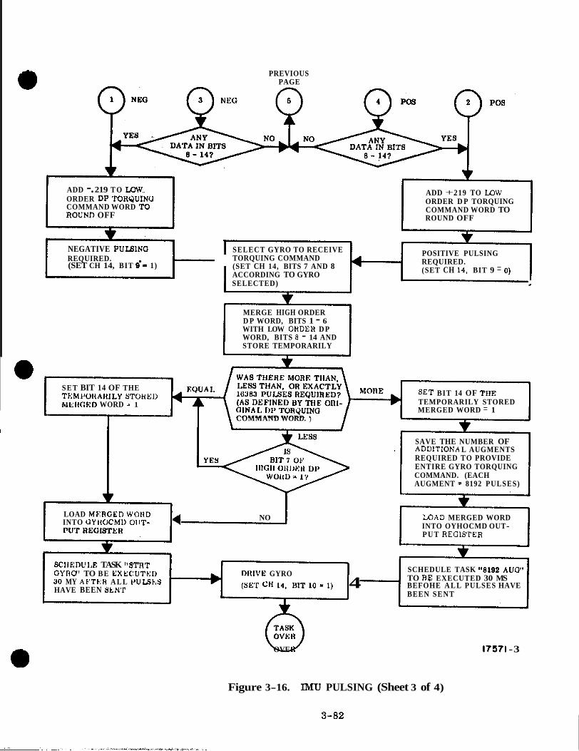
e l
PREVIOUS PAGE
ADD -. 219 T O Low, ORDER DP TOHQUINO COMMAND WORD TO ROUND OFF
ADD +. 219 TO LOW ORDER D P TORQUING COMMAND WORD TO ROUND OFF
\
NEGATIVE WLBING SELECT GYRO TO RECEIVE REQUIRED. TORQUING COMMAND (SET CH 14, BIT 9'1 1) (SET CH 14, BITS 7 AND 8
ACCORDING TO GYRO SELECTED) I
POSITIVE PULSING REQUIRED. (SET CH 14. BIT 9 = 0 )
I
MERGE HIGH ORDER D P WORD, BITS 1 - 6 WITH LOW ORDER D P WORD, BITS 8 - 14 AND STORE TEMPORARILY
S E T BIT 14 OF THE TEMI'OItAItILY STOHED ML:IfGRD WORD = 1
S E T BIT 14 OF TAR TEMPORARILY STORED MERGED WORD = 1
COMMAND WORD. )
4
SAVE THE NUMBER OF ADDITIONA L AUGMENTS REQUIRED TO PROVIDE ENTIRE GYRO TORQUING COMMAND. (EACH AUGMENT = 8192 PULSES)
'
LOAD MKRQED WOl?D
PlJ'P HECilSTEH INTO GY ItOCMI) OlIT- I NO W A D MERGED WORD
INTO OYHOCMD OUT- P U T REGIS'I'ER -
K I I E D U I S TASK "STRT QYRCY' TO B E EXECUTE11 DIIIVE GYRO
HAVE BEEN YENT
SCHEDULE TASK l'8192 AUG" TO RE EXECUTED 30 MS
BEEN SENT 30 MY APTEH A L L L'UL915S ( w r 14, HIT 10 - 1 ) 4 BEFOHE A L L PULSES HAVE
0 OVE H 17571 -3
Figure 3-16. IMU PULSING (Sheet 3 of 4)

8102AUG
2 WE CAGING?
WILL ONE MORE AUGMENT (8192 PULSES) COMPLETE THE GYRO TORQUING COMMAND?
SET BIT 14 OF THE
REQUIRED OUTPUT REGISTER = 1 OF ADDITIONAL AUGMENTS CONTENTS OF GYROCMD DECREMENT THE NUMBER
8
SCHEDULE TASK "STRT
HAVE BEEN SENT A
OUTPUT REGISTER = 1 30 MS AFTER ALL PULSES TENTS OF GYROCMD GYRO" TO BE EXECUTED SET BIT 14 OF THE CON-
J . SCHEDULE TASK "8192AUG" TO BE EXECUTED 30 MS BEFORE ALL PULSES HAVE BEEN SENT
I 1
* DRIVE GYRO (SET CH 14, BIT 10 = 1) 0 OVER
17571-4 Figure 3-16. IMU PULSING (Sheet 4 of 4)
3-83
a When the time 3 counter overflows, the task "STRT GYRO" begins. Immediately upon entering the task bits 7 through 10 of channel 14 are set to zero (gyro select a, b & c and Drive Gyro). This action deselects all gyros and disables the driving of any gyro, .Again a check to see if the IMU cage switch is "on". If so end this task and return to caller. Assuming that the IMU is not caged, the specific gyro to be pulsed is selected. (Gyros are pulsed individually in the order of Y 2 X. Each gyro will be driven to the desired position before the next gyro is selected. )
The program identifies which gyro is to be selected and provides routing in accordance with this information. Regardless of which gyro is selected, the double precision word associated with that gyro is extracted and stored for interrogation. The interrogation consists of looking at the high order word first to identify whether or not the contents are zero. If the high order word is zero, the low order word is checked for a possible com- mand. A logic one in the low order seven bits of the low order word does not necessarily mean that a pulse will be generated since the binary point is located between bits 7 and 8. In order to round out any low order bits a + o r -. 219 is added to the low order word to force any "borderline case" to result in a full pulse. If the addition of + or -. 219 to the low order 7 bits of the low order word does not yield one pulse (a 1 in bit 8), the low order 7 bits a re ignored. After the rounding is completed, negative or positive pulsing is selec- ted. In addition to directional information, routing information as to which gyro is to be serviced must be provided.
In order to acquire the resultant 14 bit data word used to drive the gyros, the double pre- cision words are merged by using bits 8 - 14 of the low order word and bits 1 - 6 of the high order word. This merging operation is explained in detail on Figure 3-17. A check is made to see if there is more than, less than, or exactly 16383 pulses to be sent.
If there is exactly 16383 pulses to go a logic 1 is set in bit 14 of the merged data word and the entire word is placed in the "GYROCMD" output register and the task "START GYRO' is scheduled to be executed in X sec. (Where X will be calculated based on the number or pulses required. If the number of pulses is less than 16383, the high order word is examined to see if bit 7 = 1. If so, it is added to the merged word before it is placed in the GYROCMD output register and the "START GYRO" task is scheduled to be executed in X mc.
If, however, the original DP pulsing words indicated more than 16383 pulses, bit 14 is added to the merged data and is set in the ''GYROCMD'' register. Now, a different task is scheduled for X sec. The task "8192 AUG" is used for large pulse train outputs and is rescheduled as long as the required output after sequential loops exists. NOTE: Each time thru task "8192 AUG" 8, 192 pukes are added to the GYROCMD register. After suf- ficient pulse trains have been sent to reduce the required pulses to zero, task "STRT GYRO" is scheduled to complete the pulsing requirements of the other gyros. Note that in any case, the final action is to set bit 10 of channel 14 = 1 causing the gyro drive sequence.
The routine for pulsing the gyros does the following:
a. Determines direction and amount of pulsing.
b. Services and reschedules itself.
c, Identifies desired gyro to be serviced (Y Z X).
d. Terminates itself.
3-84

3 .6 AOTMARK ROUTINE
The LM Optical Sighting MARK Routine, AOTMARK, incorporates two different star sighting procedures to implement alignment of the LM IMU during periods of free fall and prior to launch from the lunar surface. A description of AOTMARK is presented after a brief description of the Alignment Optical Telescope (AOT) and the procedures used to obtain s tar data during the in-flight and non-flight modes. A more detailed description of the LM optics can be found in MIT R-466. Also included, figure 3-20 is a flow diagram showing the astronaut dieplays and the general functions of the LGC during the sighting MARK routine.
3 . 6 . 1 ALIGNMENT OPTICAL TELESCOPE (AOT). The AOT is a unity power peri- scope with a 60 degree field of view. The shaft axes of the telescope is parallel to the X-axis of the LM. The center of the field of view forms an angle of 45 degrees with the LM thrust or X-axis. By means of a pinion knob, the astronaut may rotate the telescope head assembly about the shaft axis. This shaft angle rotation, shown in figure 3-18, is detented at three viewing positions: the vehicle X Z plane (zero rotation), 60 degrees to the left, and 60 degrees to the right.
Since the shaft rotation detents and the corresponding centers of fields of view (elevation) will not be exactly f 60 degrees and 45 degrees respectively, a table of the actual values corresponding to the particular AOT in use will be stored in the LGC memory. The
the correct values of azimuth and elevation. 0 astronaut need only specify one of three code numbers (DETENT) listed below to obtain
The AOT reticle pattern is shown in figure 3-19. The pattern consists of two straight lines and a spiral which is so constructed as to depart radially from the 'center as a linear function of the rotation about the center. The astronaut can rotate the entire reticle pattern about the center of the field of view by turning a knob near the eyepiece. A micrometer readout is provided near the knob to indicate the amount of reticle rotation.
3 .6 .2 NON-FLIGHT STAR SIGHTING. To perform a s tar sighting from the lunar surface, the AOT shaft is rotated to one of the three viewing positions (DETENT) such that the desired s ta r falls within the field of view. The astronaut rotates the reticle pattern until the Y reticle line intersects the star, The micrometer dial is read and the rotation angle (Y ROT) is recorded. The astronaut then rotates the pattern until the spiral intersects the s tar and this rotation ( S ROT) is recorded. These two angles keyed in by the astronaut along with the DETENT code provide sufficient data to determine a s tar direction. Only one MARK is required for a s tar sighting for the non-flight mode. The X MARK button is used to perform this MARK. 3 .6 .3 IN-FLIGHT STAR SIGHTING. During free fall the astronaut uses only the straight lines of the reticle pattern to perform a s tar sighting. The reticle pattern is set at zero rotation and the spacecraft attitude is changed so as to produce crossings of the Y and X reticle lines by the navigation star. When the star intersects the Y reticle line, the astronaut presses the Y MARK button, The X MARK button is pressed when the s tar intersects the X reticle line. Since the crossing of a reticle line by a star defines a plane containing the star , the crossing of two different lines by a single star defines the
by the astronaut in order to complete the s tar sighting. @ direction of the star. In addition to the two MARKS, the DETENT code must be entered
3-86

LEM Z AXIS
FIELD
F \
AOT
\I
Figure 3-18, LM AOT Azimuth Positions
t RE-ENCE
Figure 3-19. AOT Reticle Pattern -
IN-FLIGHT - DETENTCODE AOT RETICLE
ROT. ANGLES - NON-RIGHT
a Although the optical sighting procedures are different for the two flight modes, the sequence of operations performed by the astronaut are the same as-illustrated in figure 3-20.
During the MARKing phase of the routine, one of three verbs will be displayed to indicate to the astronaut the MARKs that are wanted. The following i s a description of these verbs,
Verb 51 This is a request to the operator to perform a MARK using the X MARK button. During in-flight operations this request would normally appear after a Y MARK has been performed. During non-flight operations this verb is the only MARK request to appear.
Verb 52 This is a request to the operator to perform a Y MARK, This verb will not appear as a MARK request during non-flight operations,
Verb 53 This verb is normally used during in-flight operations to indicate to the operator that two MARKs (an X MARK and a Y MARK) are wanted. The operator ie free to press either the X or Y MARK button a t his convenience.
After the required MARKs have been made, Verb 21, Noun 30 will be displayed indicating that the sighted star code is wanted. If the operator is satisfied with the MARKs, he will key in the star code and press the ENTER button ahowing MARKs accepted (MK ACCEPT).
3.6.4 AOTMARK ROUTINE. The AOTMARK routine is called up for each star sighting which prepares the LGC to accept MARK8 and sighting data for one of the two flight modes. For in-flight alignment of the LM IMU, both an X MARK and a Y MARK are re- quired and for non-flight alignment only an X MARK is required.
The program sets up a VAC area for storage of the MARK and sighting data and stores the VAC area address and desired flight mode in MARKSTAT as follows:
BITS
1-9 VAC Area Address
10 = 0 Initially to indicate an X MARK ie wanted = 1 after an X MARK is performed
11 =O Initially to indioate a Y MARK is wanted (in-flight only) =1 after a Y MARK is performed
12 =O while MAR- are being performed =1 after a MK ACCEPT (ENTER)
13 =O after each MARK =1 after each MK REJECT
14 -0 for non-flight MARKs =1 for in-flight MARKs
15 =O
3-88
Upon entering AOTMARK, c(MARKSTAT) is tested and if found to be > + 0, the MARK buttons are busy and Alarm (105) is fired and the job terminated. If + 0, the buttons a re available and an idle VAC area is found. If none is available, Alarm (1207) is fired and the job aborts, Refer to figure 3-21. a After a VAC area is found and reserved, the GETMKS job is scheduled via the executive NOVAC routine. Job GETMKS initiates to appropriate verb code to be flashed (VS3 for inflight or V51 for non-flight). The job is then put to sleep until the star code is entered via the DSKY.
Upon receiving a mark, the MARK RUPT routine is entered. The ISS CDU angle and time a re recorded and stored for later use and control is transferred to the appropriate routine to process the input (mark X, mark Y , mark reject o r descent bit) which caused the MARK RUPT.
If the MARK RUPT was caused by a mark X o r Y, a check is made to insure that the particular mark was not made previously c(MARKSTAT). If the particular mark was marked a second time, the PROGRAM CAUTION lamp is lit along with the failure code 00114. If not marked twice, the CDU X, Y, 2 and time information is transferred into the VAC area reserved for the AOTMARK and the REMARK routine is performed.
REMARK schedules the CHANGE VB job via the executive and sets up the information usedin changing the verb display. CHANGE VB causes the appropriate verb code to be displayed, V52 is displayed if a MARK Y is needed, V51 is displayed if a MARK X is needed, V53 is displayed if a MARK REJECT occurred (INFLIGHT) or V21 N30 is displayed if both marks have been entered.
Upon entering the star code, MK CHEK is performed. MK CHEK checks for both marks, accepts marks and requests the AOT detent code V21 N43. Af te r entering the AOT detent code, the AOT elevation and azimuth detent calibration is stored in the VAC area for later use and the tilt compensation is calculated and stored in the VAC area. If this is a non-flight AOT mark, the AOT reticle angles must also be loaded. The VAC area reserved for the AOTMARK routine will contain the following information for the two flight modes.
INFLIGHT NON-FLIGHT
VAC TIME 2 TIME 2
V A C + l TIME 1 TIME 1 VAC +2 CDU Y (XMARK) CDU Y v.4c +3 CDU Y (YMARK) Y ROT
v.4 c +5 CDU Z (YMARK) S ROT VAC+4 CDU Z (XMARK) CDUZ
VAC+6 CDU X (XMARK) CDU X VAC+7 CDU X (VMARK) BLANK VAC+8 AZIMUTH AZIMUTH VAC + E E LEVATION ELEVATION
3-89

Q vu E MARK SYSTEM
PROGRAM CAUTION
1 I I
I R 1 = 00105 (MARK BUTTONS NOT AVAILABLE)
1 -y AREA AVAILABLE?
Y E S
r STORE ADDRESS OF VAC AREA +1 IN MARKST.4T
INITIALIZE MARK B U F F E R I ( S E T X Y MARK = 0 ) I
(SET VACUSE = 0 )
1 = INFLIGHT 0 = NON FLIGHT I INDICATE T Y P E OF
MARK SIGHTING ( S E T MARK S T A T B I T 14 =
I 1 OR 0 )
. SCHEDULE JOB " G E T MKS' VIA NOVAC WITH PRIORITY 32
e PROGRAM CAUTION
R 1 = 01207 (NO VAC AREAS AVAILABLE)
F O R C E T C T R A P
I
A W '
18522- I
Figure 3-21. AOTMARK Routine (Sheet 1 of 9)
3-90

INITIALIZE X Y MARK (SET XYMARK =
INFLIGHT MARK SIGHTING?
INDICATE Y MARK (SET MARKSTAT BIT 11 = 1)
V53 FLASH PLEASE MARK X OR Y
(PLEASE MARK)
1
PUT JOB "GET MKS' ASLEEP AND WAIT FOR DSKY ENTRY
I
NO v33 OR 18522-2 v34
Figure 3-21. AOTMARK Routine (Sheet 2 of 9)
3-91

READ AND STORE CDU Y . Z AND X AND TIME 1 AM) 2 COUNTERS IN RUPTSTOR THROUGH RUPTSTOR+G
I
YES
PROGRAM CAUTION
ACCEPTED?
W
R 1 = 00112 (MARKS NOT BEING
18522-3
Figure 3-21. AOTMARK Routine (Sheet 3 of 9)
3-92
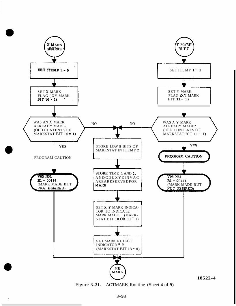
0 X MARK
SET ITEMP 1 = 1
1 . 1 S E T ITEMP 1 = 0
1 B I T 1 0 5 ; ) * , 1 S E T X MARK FLAG ( XY MARK
SET Y MARK FLAG (XY MARK BIT 11 = 1)
WAS AN X MARK ALREADY MADE? ALREADY MADE? (OLD CONTENTS O F (OLD CONTENTS OF MARKSTAT BIT 1 0 = 1) MARKSTAT BIT 11 = 1)
NO NO WAS A Y MARK
I I
1 YES
PROGRAM CAUTION
(MARK MADE BUT NOT DESIRED)
I STORE LOW 9 BITS OF MARKSTAT IN ITEMP 2
L STORE TIME 1 AND 2, A N D C D U X Y Z I N V A C AREARESERVEDFOR
SET X Y MARK INDICA- TOR TO INDICATE
STAT BIT 10 OR 11 = 1) MARK MADE. (MARK-
I S E T MARK R E J E C T INDICATOR = 0 (MARKSTAT BIT 13 = 0)
m PROGRAM CAUTION
(MARK MADE BUT
W Figure 3-21. AOTMARK Routine (Sheet 4 of 9)
3-93
18522-4
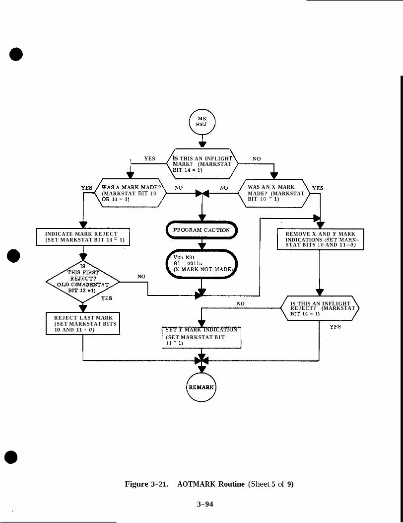
, YES ( IS THIS AN INFLIGHT MARK? (MARKSTAT
WAS A N X MARK
BIT 10 = 1) (MARKSTAT BIT 10 MADE? (MARKSTAT
INDICATE MARK R E J E C T REMOVE X AND Y MARK (SET MARKSTAT B I T 13 = 1) INDICATIONS (SET'MARK-
STAT BITS 10 AND 11= 0 )
r NO IS THIS AN INFLIGHT
REJECT? (MARKSTAT
REJECT LAST MARK (SET MARKSTAT BITS 10 AND 11 = 0) S E T Y MARK INDICATION
(SET MARKSTAT B I T 11 = 1)
I
A REMARK
Figure 3-21. AOTMARK Routine (Sheet 5 of 9)
3-94

c 5 S E T MKDEX = 0
HAS A Y MARK B E E N
(MARKSTAT BIT 11 = 1)
YES
INDICATE Y MARK REQUIRED ( M K D M BIT 8 = 1)
1
' HAS AN X MARK BEEN
(MARKSTAT B I T 10 = 1)
v YES INDICATE X MARK REQUIRED (MKDEX BIT 7 = 1)
SCHEDULE JOB CHANGE V B VIA NOVAC WITH A PRIORITY OF 32 -1 A STORE MKDEX IN MPAC FOR DISPLAY DETERMINATION (X OR Y MARK)
7 x 2 2 - 6
Figure 3-21. AOTMARK Routine (Sheet 6 of 9)
3-95

IS A MARK
C(MPAC) = > + O
ARE BOTH X AND Y MARKS REQUESTED? (MPAC BITS 7 8- 8 = 1) (REQUEST LOAD OF
(PLEASE MARK NO
REQUEST IS PRESENT? (MPAC BIT 7 OR 8 = 1)
X MARK
Figure 3-21. AOTMARK Routine (Sheet 7 of 9)
3-96
18522-7
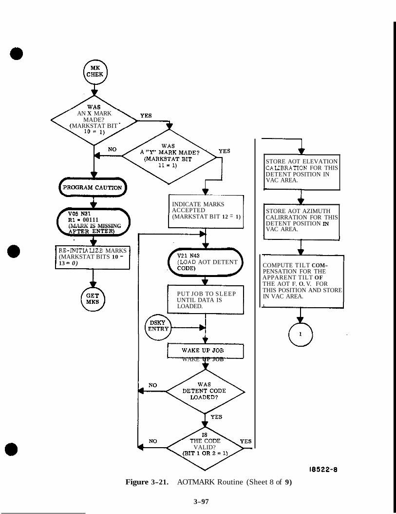
Q < AN X MARK
MADE? (MARKSTAT BIT -
I 1
R1- 00111 (MARK IS MISSING
INDICATE MARKS ACCEPTED (MARKSTAT BIT 12 = 1)
- RE-INITLALIZE MARKS (MARKSTAT BITS 10 - 13 = 0)
-- WAKE UP JOB
(LOAD AOT DETENT
PUT JOB TO SLEEP UNTIL DATA IS LOADED.
I ENTRY
THE CODE VALID?
1 STORE AOT ELEVATION CAUBRATION FOR THIS DETENT POSITION IN VAC AREA.
STORE AOT AZIMUTH CALIRRATION FOR THIS DETENT POSITION IN VAC AREA.
COMPUTE TILT COM- PENSATION FOR THE APPARENT TILT OF THE AOT F. 0. V. FOR THIS POSITION AND STORE IN VAC AREA.
18522-8
Figure 3-21. AOTMARK Routine (Sheet 8 of 9)
3-97

NON-FLIGHT
NO FOR AN INFLIGHT SIGHTING?
(MARKSTAT BIT
7 I (LOAD COMP 1 AND 2 c OF THE AOT
ANGLES)
PUT JOB TO SLEEP UNTIL DATA IS LOADED
f3-d ENTRY
4 WAKE JOB
STORE Y ROTATION ANGLE IN VAC AREA +3
- STORE SPIRAL ANGLE IN VAC AREA +5
7 CLEAR HIGH 5 BITS OF MARKSTAT I
SCHEDULE TASK ENDMARKS VIA WAITLTST TO BE EXECUTED IN 10 MSEC
0 MARKS
SET INTERNAL FLAG INDICATING GOOD END TO MARK
OVER
I852 2-9 FfDre 3-21. AOTMARK Routine (Sheet 9 of 9)
3-98

SECTION IV
MISCELLANEOUS ROUTINES
INTRODUCTION
This section of the study guide presents routines that perform various functions which are not categorized in the other sections of the study guide. The routines presented in this section are as follows:
a. PROGRAM ALARM
b. PROGRAM ABORT
c. FRESH START & RESTART
d, SELF-CHECK
4 .1 PROGRAM ALARM ROUTINE
The Program Alarm routine is used by all programs which require the display of a program alarm condition. The routine illuminates the Program Caution indicator and causes Verb 05, Noun 31 to be displayed'and a failure number to be displayed in R1, Verb 05, Noun 31 indi- cates; display octal component 1, 2, 3 - FAILREG, SFAIL, ERCOUNT. The failure number displayed in R1 is supplied by the processing function which is using the Program Alarm rou- tine. This number indicates what failure condition was detected. Table 4-1 lists the failure numbers for the program detected failures processed by this routine.
The program alarms processed by this routine are of a nature which does not require the restarting of the computer operations, Other program caution conditions which require a restart, a re processed by the Program Abort routine.
The flow chart for the Program Alarm routine is shown in figure 4-1. Control is routed to this routine by an internal calling program whenever a program alarm condition is detected. The calling program also provides the failure number. Upon entry to the routine, the return address of the calling program is stored. Then, a check is made to determine if this is the first alarm condition since the ERROR RESET key of the DSKY was used. If it is the second failure, bit 15 of FAILREG is set to a binary 1 to indicate a multiple failure and control is returned directly to the calling program using the stored return address. It should be noted that if the T4RUPT routine has already provided the e r ro r number for the first failure to the DSKY display (Rl) the multiple failure will not be indicated to the operator. If, however, the second e r ror is detected and bit 15 of FAILREG is set before the display R 1 will indicate LUUIXX. If it is the third or more failure, control is returned directly to the calling program,
If this is the first alarm condition since an Error Reset, bit 9 of output channel 10 is set to a binary 1 to illuminate the PROGRAM CAUTION lamp, Then the job DOALARM is sched- uled to be executed using the Executive's NOVAC subroutine. After performing the schedul- ing, the FAILREG (FAILURE NUMBER REGISTER) is set to the failure number supplied by the calling program and control is returned to the calling program using the return address.
4- 1

FROM CALLING
PROGRAM
STORE RETURN ADDRESS
3 OR MORE 2nd
SINCE ERROR
PROGRAM CAUTION
SCHEDULE JOB DOALARM ON EXECUTIVE VIA NOVAC 1
SET FAIL REG TO ALARM NUMBER FROM CALLING PROG *
m
* *
INDICATE MULTIPLE FAILURES (SET FAIL REG, BIT 15 = 1)
b
USE STORED RETURN ADDRESS TO RETURN TO CALLING PROG.
Figure 4-1. Program Alarm (Sheet 1 of 2)
4-2
I
17555
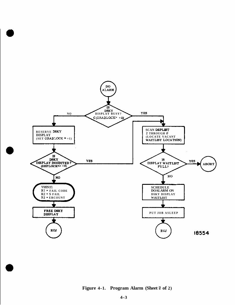
NO D I S P L A Y B U S Y ? C(GRABLOCI(> +0)
R E S E R V E WKY DISPLAY ( S E T GRABLOCK zs + 1 )
I
SCAN DSPLXET 2 THROUGH 0
A 4
VOSN31 R I = F A I L CODE R2 = S F A I L R 3 = E R C O U N T
W
( L O C A T E VACANT
t SCHEDULE 1 DOALARM ON DSKY DISPLAY WAITLIST
P U T J O B A S L E E P
18554
Figure 4-1. Program Alarm (Sheet 2 of 2)
4-3

When the processing of the DOALARM job is initiated, it obtains the use of the DSKY's through the normal procedure. Having obtained the use of the DSKY the display table is set to display Verb 05, Noun 31 and the contents of FAILREG (the failure number) in R1. The DSKY interlock is then released and the DOALARM job is terminated by routing control to the End Of Job routine.
Table 4-1. Failure Numbers For Program Alarms
h o g . Alarm No. Prog. Alarm Condition ~~
3PTICS SUB-SYSTEM
00105 Mark Buttons Not Available
00111 Mark Is Missing After Enter
00112 Mark Not Being Accepted
00113 No Inbits
00114 Mark Made But Not Desired
00115 X Mark Not Made
INERTIAL SUB-SYSTEM 002 06 Zero CDU Not Allowed With Coarse A l i g n or Gimbal Lock 00207 00210
ISS Turn-on Request Not Present For 90 Set. IMU Not Operating
00211 Coarse Align Error
00212
00213
PIPA Fail But PIPA Is Not Being Used
IMU Not Operating With Turn-on Request
002 14 Program Using IMU When Turned OFF
4-4
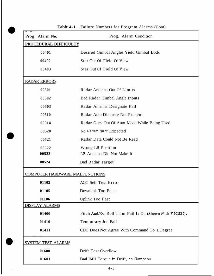
Table 4-1. Failure Numbers for Program Alarms (Cont) _ _ ~ ~ ~
Prog. Alarm No. Prog. Alarm Condition
PROCEDURAL DIFFICULTY
00401 Desired Gimbal Angles Yield Gimbal Lock
00402 Star Out Of Field Of View
00403 Star Out Of Field Of View
RADAR ERRORS
00501 Radar Antenna Out Of Limits
00502 Bad Radar Gimbal Angle Inputs
00503 Radar Antenna Designate Fail
00510 Radar Auto Discrete Not Present
00514 Radar Goes Out Of Auto Mode While Being Used
00520 No Radar Rupt Expected
00521
00522 00523
00524
Radar Data Could Not Be Read
Wrong LR Position LR Antenna Did Not Make It
Bad Radar Target ~~ ~~ ~~~
COMPUTER HARDWARE MALFUNCTIONS
01102
01105
01106
AGC Self Test Error
Downlink Too Fast
Uplink Too Fast DISPLAY ALARMS
01400 Pitch And/or Roll Trim Fail Is On (Shown With V50N25).
01410 Temporary Jet Fail
01411 CDU Does Not Agree With Command To 1 Degree ~~~~~ ~
~~ -~
SYSTEM TEST ALARMS
01600 Drift Test Overflow
01601 Bad IMU Torque In Drift, In Compass
4-5

4.2 PROGRAM ABORT ROUTINE
The Program Abort routine is used by internal programs which have detected a program abort condition. A program abort condition requires that the computer operations be restarted. Otherwise, the computations or functions being performed would be erroneous or could not be completed.
The end result of a program abort, besides the restarting of the computer's processing, is the illumination of the PROGRAM CAUTION indicator and the display of Verb 05 , Noun 31 and a failure number in R1. Table 4-2 tabulates the failure numbers associated with pro- gram abort conditions. The processing performed by the program abort routine is shown In figure 4-2.
Upon entry to the Program Abort routine the failure number is available from the internal program which detected the failure condition. The first item accomplished is a check to determine if this is the first failure since the last time the ERROR RESET key was used. If it is the first failure, bit 9 of output channel 10 is set to a binary l ' to illuminate the PROGRAM CAUTION lamp. Then the FAILREG is set to the failure number which was supplied by the internal calling program.
Then, whether this is the first failure or not, a TC TRAP condition is generated. This is accomplished by having a TC (TRANSFER CONTROL) instruction transfer control it itself, After about 10 ms, the computer's TC TRAP detecting circuitry will detect this condition. When it does, a restart 'is forced which is similar in nature to the program interrupts. Control i s forced to the Restart routine. The Restart routine among its other functions causes the dieplay of Verb 05, Noun 31 and the failure number in R1.
4 .3 FRESH START AND RESTART ROUTINE
The Fresh Start and Restart routines are closely related and will be presented together. The Fresh Start routine provides the computer with the capability of initialization when the comptter is first turned on or if a major malfunction occurs which requires almost total initialization1 The Restart routine also prwides an initialization function but not as com- plete as is performed by the Fresh Start routine. The Restart routine restarts programs at some logical point in their execution. However, when a restart is being performed and the two phase tables maintained by the Phase Table Maintenance routine do not agree, a Fresh Start is essentially performed. Thr Fresh Start routine is entered as a result of entering Verb 36 via the DSKY or uplink. The Restart routine Is entered whenever one of the following malfunctions is detected. a. PARITY FAIL b. POWER FAIL c. RUPT LOCK d. TC TRAP The TC TRAP condition is purposely generated by the Program Abort routine if any program abort condition exist. The processing performed by the Fresh Start and Restart routines is shown by the flow chart in figure 4-3.
4-6
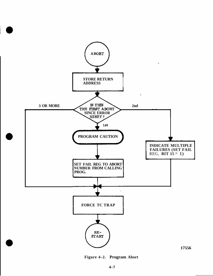
STORE RETURN I ADDRESS I
I
3 OR MORE 2nd
SINCE ERROR
PROGRAM CAUTION r
INDICATE MULTIPLE FAILURES (SET FAIL REG, BIT 15 = 1)
1
SET FAIL REG TO ABORT NUMBER FROM CALLING PROG.
FORCE TC TRAP
Figure 4-2. Program Abort
4-7
17556
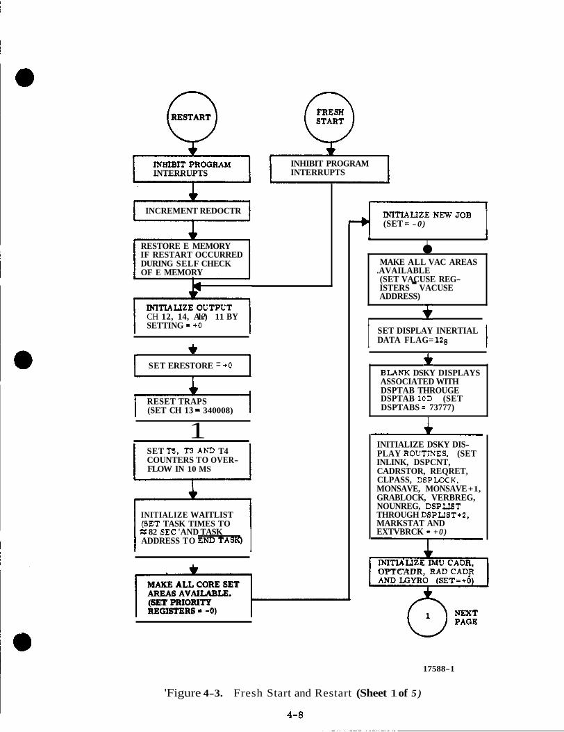
0 RESTART
INTERRUPTS
INCREMENT REDOCTR
RESTORE E MEMORY IF RESTART OCCURRED DURING SELF CHECK OF E MEMORY
CH 12, 14, Ah?) 11 BY SETTING = +O
+ SET ERESTORE = + O
RESET TRAPS (SET CH 13 = 340008) I
1 SET T5, T3 AhP T4 COUNTERS TO OVER- FLOW IN 10 MS
INITIALIZE WAITLIST f6ET TASK TIMES TO
I I % 82 SEC 'AND TASK ADDRESS TO Em
1 MAKE ALL CORE SET AREAS AVAILABLE. (SET PRIORITY REGISTERS 9 -0)
(SET = -0) I 1 1
I
MAKE ALL VAC AREAS .AVAILABLE (SET VACUSE REG- ISTERS - VACUSE ADDRESS)
I
INHIBIT PROGRAM INTERRUPTS
r
-
I I SET DISPLAY INERTIAL DATA FLAG= 128
B U M ( DSKY DISPLAYS ASSOCIATED WITH DSPTAB THROUGE DSPTAB 10D (SET DSPTABS = 73777)
I A
INITIALIZE DSKY DIS- PLAY ROUTTh'ES. (SET INLINK, DSPCNT, CADRSTOR, REQRET, CLPASS, DSPLOCK, MONSAVE, MONSAVE +1, GRABLOCK, VERBREG, NOUNREG, DSPLIST THROUGH DSPLIST+O, MARKSTAT AND EXTVBRCK * + 0 )
I
OPTCADR, RADCADP
A E I
17588-1
'Figure 4-3. Fresh Start and Restart (Sheet 1 of 5 )

SET T4 ROUTING SWITCH (DSRUPTSW) = +o
SET NOUT=000138 AND SAMPLIM"77776g
FRESH START
SET DSPTAB + 11D = 400008 TO TURN OFF THE ASSOCIATED DSKY DISPLAYS
SET MODES 33' 16000 (NO PIPA OR
SET FAIL REG'+O
INITIALIZE SELF CHECK BY SETTING SELFRET = 021018 (GENADR)
I 77754 (m) SET DSPCOUNT E
SELECT NOMINAL
* RESTART
SET DSPTAB + I I D 404408 TO BLANK THE ASSOCIATED DSKY DISPLAYS EXCEPT PRW CAUTION & GIMBAL LOCK
1
SET O/P CH12 BIT 4 = 1 (COARSE ALIGN) I
I SET T5RUPT FOR DAPIDLER PROG I
SCHEDULE DOALARM VIA THE EXEC NOVAC WITH A PRIORITY OF 378 (TO DISPLAY C(FA1L REG)
I
6 6 18556-2

Q RESTART
*
* YES AN LMPCMD
I REISSUE THE LMP CMD (SET O/P CHI0
I I I BIT X 5 =: 1)
I UPDATE LMP REF. POINTER (LMPOUT) & SET LMPOUTT = - 1
1
INITIALIZE T4LOC FOR NORMAL T 4 RUPT
f I CHECK EACH PHASE I
I AGREEMENT IN ORDER FROM 5- 0
18556-3
Figure 4-3. Fresh Start and Restart (Sheet 3 of 5)
4-10

- "RESH
0 1 1 0 7 ~ FOR DISPLAY LESTART
IN RZU(PHASE TABLE DISAGREEMENT IN I
INITIALIZE BY SETTING TO +0: SMODES, MODREG, AGSWORD, UPLOCK, CDU, COUNTERS, LMPCMDS, LMPTN, LMPOU" 6 PHASE 0 + 5
I .
I INITIALIZE BY SETTING TO - 0 PHASE 0 - 5 I
INITIALIZE LMPOUTT BY SETTING TO -1
INITIALIZE T4 LOC FOR NORMAL T4 RUPT
ALL PHASE NUMBERS AGREE 7
INACTIVE
1 d GROUPS 5 THRU 2
) N O A PHASE DATA
--.-UIINATE
< GOOD 7 >
SCHEDULE THE
INITIALIZE IMODES 30 FOR FRESH START (SET IMODES 30 - 37411)
SCHEDULE lFAILOK ON WAITLIST TO OCCUR IN 5 SEC. NO
J
SET T5 ADR. FOR SETIDLER (TO INSURE A ONE SEC. DELAY BEFORE DAPIDLER) RETAIN 1MODESBO SET DAPBOOIS - 04016 6 FAIL INIIIBITS (1, 3, 4 & 5) IMTLAUZE STATE -STATE & RESET ALL IMU FAIL + 3 (SET TO +0) BITS (9 THRU 14 = 1)
18556-4
.Figure 4-3. Fresh Start and Restart (Sheet 4 Of 5)
4-11

YES \ LAMP STILL 7
- NO
1'
I SET lMODES 30 BIT 9 (IMU OPERATE) I
I I TO + O I (SO THAT T4 WILL NOT ZERO CDUS)
I I I
I I RELEASE PROGRAM INTERRUPT INHIBIT
DISPLAY MAJOR I MODE I 6 TO DUMMY
18556-5
Figure 4-3. Fresh Start and Restart (Sheet 5 of E)
4- 12
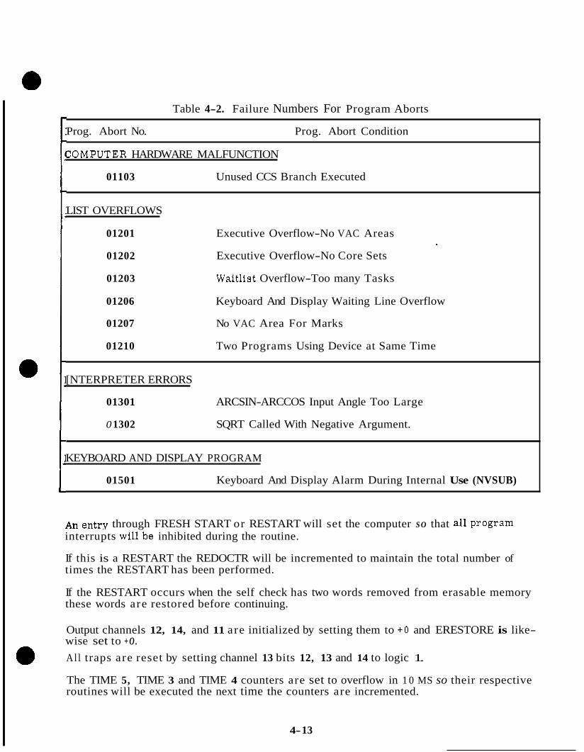
Table 4-2. Failure Numbers For Program Aborts
Prog. Abort No. Prog. Abort Condition
ZOMPUTER HARDWARE MALFUNCTION
01103 Unused CCS Branch Executed
LIST OVERFLOWS
01201 Executive Overflow-No VAC Areas
01202 Executive Overflow-No Core Sets
01203 Waitlist Overflow-Too many Tasks
01206 Keyboard And Display Waiting Line Overflow
01207 No VAC Area For Marks
01210 Two Programs Using Device at Same Time
[NTERPRETER ERRORS
01301 ARCSIN-ARCCOS Input Angle Too Large
0 1302 SQRT Called With Negative Argument.
KEYBOARD AND DISPLAY PROGRAM
01501 Keyboard And Display Alarm During Internal Use (NVSUB)
An entry through FRESH START or RESTART will set the computer S O that ail Program interrupts willbe inhibited during the routine.
If this is a RESTART the REDOCTR will be incremented to maintain the total number of times the RESTART has been performed.
If the RESTART occurs when the self check has two words removed from erasable memory these words are restored before continuing.
Output channels 12, 14, and 11 are initialized by setting them to + O and ERESTORE is like- wise set to + O .
Al l traps are reset by setting channel 13 bits 12, 13 and 14 to logic 1.
The TIME 5, TIME 3 and TIME 4 counters are set to overflow in 1 0 MS so their respective routines will be executed the next time the counters are incremented.
4- 13

The WAITLISTis initialized by setting all task times to approximately 82 seconds and all task addresses to ENDTASK.
All core set areas are made available for executive use by setting the priority register of each to -0. The register NEWJOB will likewise be set to -0.
Al l VAC areas are made available by setting the contents of each VACUSE register to the corresponding VACUSE address and the display inertial data flag is set to 128.
The blanking constant, 73777 is set into each DSPTAB through DSPTABlOD so that T4 will blank the DSKY displays associated with these DSPTABs when program interrupts are again allowed.
The following locations, which a re concerned with DSKY display routines are initialized by setting them to +0: INLINK, DSPLNT, CADRSTOR, REQRET, CLPASS, DSPLOCK, MONSAVE, MONSAVE+ 1, GRABLOCK, VERBREG, NOUNREG, DSPLIST, through DSPLIST+2, MARKSTAT, and EXTVBACT.
IMUCADR, OPTCADR, RADCADR, and LGYRO are all initialized by setting to +O.
The T4 routing switch (DSRUPTSW) is initialized by setting it to +O.
NOUT is set to octal 13 to serve a s a flag for the T4RUPT routine to indicate that DSPTAB 0 through DSPTAB 10D all require interrogation and consequently a change in the DSKY displays associated with these DSPTABs.
IMODES 33 FAIL bits a re reset, and RADMODES is initialized.
The SELFRET register is set so that when the computer first enters self check after a FRESH START o r RESTART it will enter at the beginning.
DSPCOUNT is initialized to octal 23, the telemetry program is initialized and the nominal downlink list is selected for transmission of downlink data.
DSPTAB 11D is set to blank all associated lamps on the DSKY if this is a FRESH START, or to blank all except PROGRAM CAUTION and GIMBAL LOCK if this is a RESTART.
If this is a RESTART the status of the coarse align enable (channel 12, bit 4) will depend on the condition of the GIMBAL LOCK lamp,
The job DOAURM is scheduled with a priority of 37 to set up the DSPTABs associated with R1 so that the contents of FAILREG will be displayed. Further action in the RESTART routine is dependent upon the condition of the MARK REJECT and the DSKY RSET pushbuttons. If the MARK REJECT and the DSKY RESET pushbuttons are pressed, the computer will essentially perform a FRESH START. Assuming this is not the case, the LM mission programmer command pointer is updated and if a LMPCMD was in progress, the command is reissued, (T4LOC) is set for a normal T4RUPT, and the phase tables are checked for agreement. The two registers in each phase table group should con- tain the complement of each other for agreement. If any group disagrees or if the phase data is bad (contains a phase larger than 127 decimal) octal code 01107 will be processed for dis- play in R2. (Phase Table Disagreement DOFSTART) and the computer will proceed as if in FRESH START,
4- 14

After all phase tables have been determined satisfactory, and all jobs associated with the active groups have been scheduled, all failure codes inIMODES30 will be reset. Although the failure codes in IMODES 30 are reset, the IMU Fail inhibits will be left intact. Had a FRESH START been requested initially or entered through RESTART, the following registers would be set to + O ; SMODES, MODREG, AGSWORD, UPLOCK, CDU Counters, LMPCMDS, LMPIN, LMPOUT, and the PHASE 0 through 5. The PHASE 0 through 5 would be set to -0 and LMPOUT T set to -0. T4LOC would be set for a normal T4RUPT and IMODES 30 inittalized. Task IFAILOK would be scheduled on the waitlist to occur in 5 seconds and the T5 address initialized. From this point on the FRESH START and RESTART routines are identical. The GIMBAL LOCK lamp is interrogated and if on IMODES 30, bit 9 is set to 0 to prevent zeroing of the CDU's.
The program interrupt inhibit is then removed and the major mode is displayed prior to entry into DUMMY JOB.
4.4 SELF-CHECK ROUTINE
There are 19 possible options in the SELF-CHECK routine. The first 18 options are used to check the internal operation of the computer (*O to *lo) while the 19th option (*ll) checks the electroilluminescent displays and associated controlling hardware on the DSKY. Options associated with i 10 or - zero will probably be used the most since all three of these options perform a complete internal self-check of the computer. However, these three options perform different diagnostic functions when an error is detected. The options associated with il to i 7 check out various parts of the computer and are useful for diagnostic testing of the computer. The normal use of SELF-CHECK is as a routine to check the computer con- tinuously when the computer is not busy with other routines. The *lo or -zero options are used for this purpose.
4 .4 .1 SELF-CHECK OPTIONS. The SELF-CHECK option depends on what is written into the SMODE register to tell the computer what option of SELF-CHECK is desired. Placing a + O in the SMODE register forces the computer to go into the backup idle loop where it continuously looks for a new job. The SMODE register is set to + O during FRESHSTART, however, the content of SMODE can be controlled by the operator through use of the DSKY.
Placing a iNON-ZERO number below octal 12 or -0 in the SMODE register starts one of the active options of SELF-CHECK. Below is a description of what section or sections of the computer the options check. A block diagram in figure 4-4 shows the options available and indicates the number to put in the SMODE register for the desired option.
il octal: SOPTION 1. Checks all pulses possible by internal control of the computer except those used exculsively by the IN-OUT instructions, In addition, SOPTION 2 will always be performed before re-entering SOPTION 1.
i 2 octal: SOPTION 2. Checks all the IN-OUT instruction pulses.
kt3 octal: SOPTION 3. Checks central processor registers and all bit com- binations.
4- 15
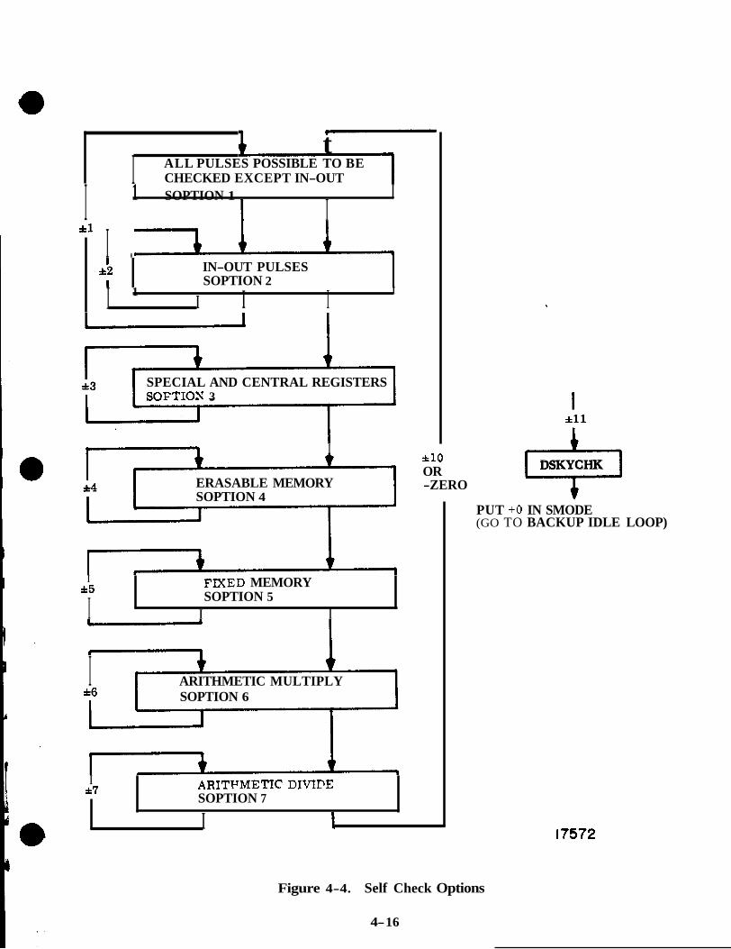
t I ALL PULSES POSSIBLE TO BE
CHECKED EXCEPT IN-OUT
I 1 SOPTION 1
1 I I
*l I . 1 IN-OUT PULSES SOPTION 2
I I I I 1 I
SPECIAL AND CENTRAL REGISTERS SOFTION 3
I I
ERASABLE MEMORY SOPTION 4
I *5
I FIXED MEMORY SOPTION 5
I I
I ARITHMETIC MULTIPLY *6 SOPTION 6
it10 OR -ZERO
1 *ll
ril DSKYCHK
PUT +O IN SMODE (GO TO BACKUP IDLE LOOP)
I a7 ARITYMETIC DIVIPE
I I SOPTION 7
17572
Figure 4-4. Self Check Options
4- 16
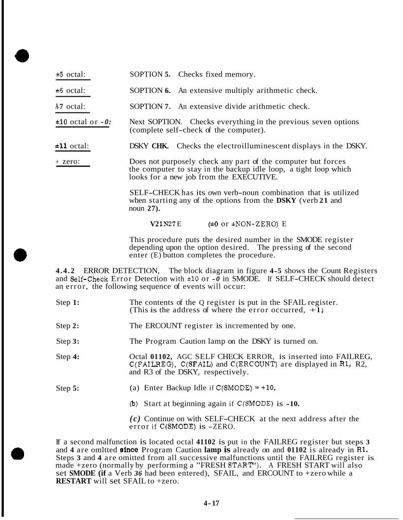
&5 octal: SOPTION 5. Checks fixed memory.
*6 octal: SOPTION 6. An extensive multiply arithmetic check.
A-7 octal: SOPTION 7. An extensive divide arithmetic check.
110 octal o r -0: Next SOPTION. Checks everything in the previous seven options (complete self-check of the computer).
*ll octal: DSKY CHK. Checks the electroilluminescent displays in the DSKY.
+ zero: Does not purposely check any part of the computer but forces the computer to stay in the backup idle loop, a tight loop which looks for a new job from the EXECUTIVE.
SELF-CHECK has its own verb-noun combination that is utilized when starting any of the options from the DSKY (verb 21 and noun 27).
V2 1N27 E ( i o or &NON-ZERO) E
This procedure puts the desired number in the SMODE register depending upon the option desired. The pressing of the second enter (E) button completes the procedure.
4 . 4 . 2 ERROR DETECTION, The block diagram in figure 4-5 shows the Count Registers and Self-check Error Detection with rtl0 or -0 in SMODE. If SELF-CHECK should detect an error , the following sequence of events will occur:
Step 1: The contents of the Q register is put in the SFAIL register. (This is the address of where the error occurred, +l. )
Step 2: The ERCOUNT register is incremented by one.
Step 3: The Program Caution lamp on the DSKY is turned on.
Step 4: Octal 01102, AGC SELF CHECK ERROR, is inserted into FAILREG, C(FAILREG), C(SFA1L) and C(ERC0UNT) are displayed in R1, R2, and R3 of the DSKY, respectively.
Step 5: (a) Enter Backup Idle if C(SM0DE) = +lo.
(b) Start at beginning again if C(SM0DE) is -10.
(c ) Continue on with SELF-CHECK at the next address after the e r ro r if C(SM0DE) is -ZERO.
If a second malfunction is located octal 41102 is put in the FAILREG register but steps 3 and 4 are omltted slnce Program Caution lamp is already on and 01102 is already in R1. Steps 3 and 4 are omitted from all successive malfunctions until the FAILREG register is made +zero (normally by performing a "FRESH START'). A FRESH START will also set SMODE (if a Verb 36 had been entered), SFAIL, and ERCOUNT to +zero while a RESTART will set SFAIL to +zero.
4- 17

L
ERROR DETECTED
INCFEMFNT SCOUKT
SET CONTENTS OF (> I N SFhl l . REG.
-\
-7 I
I INCREMENT ERCOVNT
INCREMENT SCOCNT
PERFORM SOPTION 3 I *- I INCREMENT SCOUNT
R2 = c(SFA1L) R3 = c(ERC0UNT)
INCREMENT SCOUNT
PERFORM SOPTION 5 D - 1.
INCREMENT SCOUNT "7 I
+ [ PERFORM SOPTION 6 b *- -" *- -1 -4.
INCREMENT SCOUNT - 2 2 .
PERFORM SOPTION 7
INCREMENT SCOUNT+Z
L I
CONTINUE H'ITH SELF CHECK AT ADDRESS DEFINED BY SFAIL
- 10
GO TO BACK-UP IDLE
17574
Figure 4-5. Count Registers and Self Check Error Detection with *lo or -0 in SMODE
4- 18

It is possible to leave SELF-CHECK on for a long period and keep track of the number of malfunctions that have occurred by observing the ERCOUNT register. The SFAIL register will contain the e r ro r address +1 of the last malfunction.
Figure 4-6 is the flow diagram for Self Check with *1 - *7 in SMODE. The corresponding SOPTION is performed continuously until an error is detected at which time the error is displayed in the same manner as previously discussed.
4 . 4 . 3 DSKY CHECK. Putting a ill in the SMODE register (see figure 4-7) illuminates all possible electroilluminescent displays on the DSKY. The subroutine then puts a +zero in the SMODE register. This routine does not automatically check for a malfunction of the computer. It depends on an observer to watch the DSKY for the proper displays.
No useful function will be performed by putting a number larger than octal 11 in the SMODE register because no SELF-CHECK subroutines have been written for these numbers. If octal 12 or a larger number is put in the SMODE register a subroutine will change the contents of the SMODE to +zero, which forces the computer to go to the backup idle loop.
4 . 4 . 4 HOW TO USE THE DSKY TO MONITOR SELF-CHECK. The block diagram in figure 4-5 shows how the three SCOUNT registers may be utilized to monitor the opera- tion of SELF-CHECK. SCOUNT (1366) is incremented at the start of each of the seven minor loops that make up the internal computer self-check even if they are run through consecutively a s they a re when i 1 0 or -zero is in SMODE.
EXCEPTION: When i 1 0 or -zero is in SMODE SCOUNT is not incremented at the beginning of the SOPTION concerned with IN-OUT pulses.
SCOUNT +1(1867) is incremented upon the completion of the erasable memory SOPTION when i 4 , i 1 0 , or -0 is in SMODE. SCOUNT +2(1370) is incremented upon the completion of the arithmetic divide SOPTION when *7, *lo, or -0 is in SMODE. The incrementing of the SCOUNT +2 indicates the successful completion of the complete self-check of the computer. If a V15NOlE 1366E is performed on the DSKY, the contents of these three count registers will appear in R1, R2, and R3 of the DSKY, respectively.
It may be desirable, for information or diagnostic reasons, to set the three SCOUNT registers and the ERCOUNT register to zero before initiating one of the options of SELF-CHECK. If so, these four registers have to be set to zero from the DSKY. The following procedure will accomplish this operation:
Step 1: V2 lNOlE 17653 OOOOOE (ERCOUNT register)
Step 2: N15E OOOOOE (SCOUNT register)
Step 3: E OOOOOE (SCOUNT +1 register)
Step 4: E OOOOOE (SCOUNT +2 register)
4- 19
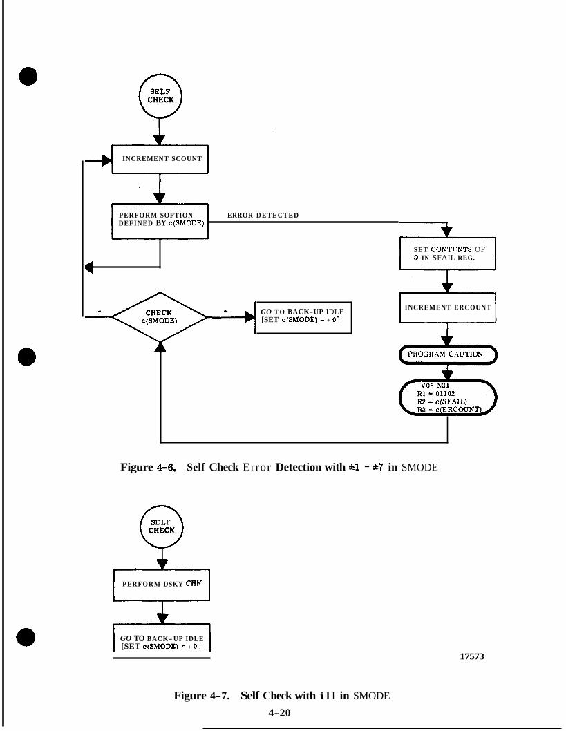
0 CHECK
INCREMENT SCOUNT
PERFORM SOPTION ERROR D E T E C T E D DEFINED BY c ( S M 0 D E )
SET COXTENTS OF Q IN SFAIL REG.
GO T O BACK-UP IDLE [SET c(SM0DE) = + 01 L
INCREMENT ERCOUNT
Figure 4-6. Self Check Error Detection with il - *7 in SMODE
0 CHECK
PERFORM DSKY CHI(
GO TO BACK- UP IDLE [SET c ( S M 0 D E ) - + 01
17573
Figure 4-7. Self Check with ill in SMODE
4-20

4.4.5 SELF CHECK FLOW. Self check (figure 4-8) is entered from DUMMY JOB whenever a job of higher priority is not scheduled. The self check routtne is composed of eight major subroutines; SOPTION 1 through 7 and DSKY CHECK. "he operator can route the computer to the desired subroutine by loading the SMODE register with the appropriate value, through the use of the DSKY. In order to cause the computer to con- tinuously perform any option the SMODE register must be loaded with the option number desired. Either a plus o r minus may be used as both will cause entry into the desired option and as long as an e r ro r is not detected the computer will react identically to both. However, if an e r ro r is detected, the computer reacts differently to a plus than to a minus value. If the SMODE register is loaded with ~ 1 0 or -0 all seven options will be performed consecutively beginning with SOPTION 1. Again, the computer reacts identically to all three of these values until an e r ro r is detected. If the SMODE register is loaded with *ll, the computer will perform the DSKY CHECK. The operator has control over the contents of SMODE, however, the computer will set SMODE to + O under certain conditions.
Upon entry into self check, the starting address of SOPTION 1 is saved to be used in case the contents of SMODE = * l O or -0.
After checking again to make sure that another job with a higher priority is not waiting, the SMODE register is checked to determine which subroutine to enter. If the SMODE register contains +0, a tight loop exists in which the computer does not perform a meaningful function, but merely continuously checks for a higher priority job or a change in SMODE. This loop is designated the "back-up idle loop".
If SMODE contains -0 or *l through *lo the SCOUNT register is incremented. This register is incremented each time to provide a total of the number of times the computer passes through this point. The SCOUNT register can be loaded through use of the DSKY.
If SMODE contains a quantity greater than +11 or less than -11, SMODE is set to + O which forces the computer into the back-up idle loop. A number larger than kll in SMODE therefore is meaningless to the computer,
If SMODE contains ill, SMODE is set to + O and DSKY CHECK is entered. The next time SMODE is checked (upon completion of DSKY CHECK) the back-up idle condition will exist.
The seven options perform the following:
SOPTION 1 Checks all instruction pulses generated by the computer except those used exclusively by the IN-OUT instructions.
SOPTION 2 Checks the IN-OUT instruction pulses. SOPTION 3 Checks the counting ability and the ability to handle overflow and
SOPTION 4 Checks erasable memory. SOPTION 5 Checks fixed memory. SOPTION 6 Checks multiply arithmetic ability. SOPTION 7 Checks divide arithmetic ability.
underflow situations.
4-21

The option specified by SMODE will be entered and upon completion (providing an error is not detected) will return to check for a scheduled job of higher priority. If none is found, SMODE will again be checked and assuming it has not been changed, the option will be repeated, The specified option will, therefore, be performed continuously whenever the computer is in SELF CHECK. If SMODE contains *l SOPTION 1 and SOPTION 2 will be performed. If SMODE contains * l O or -0, SOPTION 1 is entered and all options are performed consecutively. Again upon successful completion of the entire loop, it is repeated as long as the computer is in SELF CHECK.
Whenever an error is found, the subroutine ERRORS is entered. The address of the instruction immediately following the point where the e r ro r was detected is saved and stored in the SFAIL register and the ERCOUNT register is incremented.
The PROGRAM CAUTION lamp is lit i f not already on and V05 N31 is displayed. R1 displays the contents of FAILREG, whichis 01102 (AGC self check error); R2 displays the contents of SFAIL; and R3 displays the contents of ERCOUNT. If an e r ro r had been detected previously and the alarm displayed, the second e r ror will set bit 15 of FAILREG to 1 to indicate the existance of multiple errors.
The contents of SMODE is examined to route the computer to the desired point. If the contents of SMODE is less than -0, the option specified is entered again, at the beginning, If the contents of SMODE is -0, self check is continued at the next instruction after the point where the e r ro r was detected. If the contents of SMODE is + O or greater, SMODE is set to + O and the computer is forced into the back-up idle loop. Each of the eight major subroutines is discussed below.
SOPTION 1 - This option checks the pulses which are generated to implement all instructions, except those used exclusively with IN-OUT instructions. The method used to check the control pulses is to perform the instruction, check the result, and transfer control to the ERRORS subroutine whenever the result is not as expected, The branching type instructions are provided with direct access to the ERRORS subroutine on a wrong branch, whereas the arithmetic functions generally make extensive use of -0 CHECK, + O CHECK, -1 CHECK and +1 CHECK subroutines. Values are chosen such that when manipulated by the instruction(s) being checked a result equal to one of the above values is obtained, A failure will route control to the ERRORS subroutine.
Upon completion of SOPTION 1, SOPTION 2 is always performed before returning to check SMODE.
SOPTION 2 - This option checks all control pulses used in the IN-OUT instructions. The method used is identical to that used in SOPTION 1.
SOPTION 3 - The first part of this option is used to check the ability of the computer to count up a 14 bit number. This is accomplished by initializing SKEEP 6 to 37777 and SKEEP 7 to 40000 and decrementing SKEEP 6 and incrementing SKEEP 7 until SKEEP 6 contains + O and SKEEP 7 contains -0.
4-22
Immediately after initializing SKEEP 6 and SKEEP 7 the contents of SKEEP 6 is checked for + O . Assuming SKEEP 6 is not + O its contents minus 1 is added to the complement of its contents. The result, provided all control pulses are being generated properly, is -1. An incorrect value will cause a transfer to the ERRORS subroutine while a correct value will cause a continuation of this option. A check is made at this point to see if a new job of higher priority has been scheduled since the last time we looked. After checking for a new job, the complement of SKEEP 6 is examined. If this value is less than -0, the con- tents of SKEEP .6 is decremented; if the value is -0, SKEEP 6 is not decremented. In either case, the contents of SKEEP 6 and SKEEP 7 are added which should result in -1. A check is made for this quantity as before, after which SKEEP 7 is incremented and the loop is repeated, This action continues until SKEEP 6 contains + O . At this point SKEEP 7 should contain -0. Addition of these two quantities then will produce a -0 and the count check portion of SOPTION 3 is complete.
The second portion of SOPTION 3 checks the ability of the computer to handle overflow and underflow situations when they occur.
Initially, SKEEP 5 is set to 40000 and a maximum overflow quantity is set up. This quantity is checked, determined to be greater than +0, decremented, and stored in SKEEP 4. Next, a check is made to see if the quantity is still overflow. The low 14 bits of the overflow quantity is then added to the contents of SKEEP 5 which should result in a -1. If this is the first time through this point, a maximum underflow quantity is set up and the second half of the OVFLOW loop is entered. This time the quantity is determined to be less than -0 after which it is complemented and decremented. The quantity should still be overflow, in which case the low 14 bits is again added to the contents of SKEEP 5 to produce a -1. The computer now looks for a job of higher priority and upon finding none the contents of SKEEP 5 is diminished, the last overflow quantity checked is decre- mented, and the loop is repeated. This action continues until an overflow quantity after being decremented results in a quantity which is no longer overflow, A t this time the contents of SKEEP 5 should be -0 and the contents of SKEEP 4 should be 37777. These two values a re checked and control is either transferred to ERRORS or to the lead in section of SELF CHECK to check for a new job and to interrogate SMODE. This option is now complete and the next self check subroutine depends on the contents of SMODE.
SOPTION 4 - This option provides an extensive check of the erasable memory. Most locations are checked to make sure that the computer can write into the location and read out what was written. SOPTION 4 is begin by selecting erasable bank 00 and starting address 01462 as the first location to be checked, The address to be checked is stored in SKEEP 7. The check of the addrdss is started by saving the present contents of the address contained in SKEEP 7 a s well as the next successive address. The contents of these two addresses are then set to their own address. (e. g. ~(01462) - 01462 and ~(01463) - 01463. ) The contents of the first address is then added to the complement of the contents of the second which should provide a -1 result. Next, the content of the two addresses is set to the complement of their own address. (e. g. ~(01462) = 76315 and ~(01463) = 7.6314.) The contents of the second address is now added to the complement of the first which again will result in a -1. If either of the -1 checks is unsatisfactory, con- trol will be transferred to the ERRORS subroutine, After successful completion of these checks, the original contents of the two addresses is restored, a check for new job is made and assuming none is found, the next address is determined. Assuming we have the EBANK set to select bank 00, a few decisions must now be made. If address 01777 has not been checked, SKEEP 7 is incremented and the ERAS LOOP is performed again.
4-23
NOTE: The first time through the ERAS LOOP, addresses 01462 and 01463 were acted upon. This time, since the contents of SKEEP 7 is 01463, addresses 01463 and 01464 will be acted upon. (The second address of the first pair is the first address of the second pair. )
This loop is repeated until address 01777 has been checked at which time, since address 00062 has not been checked, SKEEP 7 is set to 00062 and the loop continues to be repeated until address 01374 has been checked.
NOTE: Even though EBANK is set to bank 00, addresses 00062 through 00377 will be picked from bank 00; addresses 00400 through 00777 will be picked from bank 01; and addresses 01000 through 01364 will be picked from bank 02. Addresses 00062 through 01374 will always be picked from these three banks regardless of the content of - EBANK.
After address 01374 has been checked, checking will continue at the desired address of the next bank. The method of checking the erasable memory with other values in EBANK is identical except that the block of addresses checked may be different. Table 4-3 shows the addresses checked and their bank designations with different contents in EBANK.
After checking erasable memory with EBANK = 7 , control is transferred to the CNTR CHECK portion of SOPTION 4. The CNTR CHECK portion of SOPTION 4 performs a CS instruction on all addresses from 00061 through 00010, and manipulates data in all shift and cycle registers. The data is chosen such that when shifted or cycled and added to a constant, the result is -1 on two occasions. The normal check for -1 is performed and the normal transfer of control to the ERRORS subroutine will follow if it fails. A satisfactory check will terminate this option, however, before returning to the lead in section of SELF CHECK to check for a new job and look at SMODE the SCOUNT register will be incremented. This register will contain the number of times we have passed through SOPTION 4.
SOPTION 5 - This option performs a check of fixed memory by adding every word in a bank together. The last word in each bank is always chosen such that the sum of all words in the bank will equal either the bank number o r the complement of the bank number.
The option begins by selecting fixed bank 0 , obtaining the first word in the bank and starting it in SKEEP 1. Since this is the first word in the bank, the next decision will be based on whether we are in ROPECHK (SOPTION 5) or SHOWSUM. (SHOWSUM is a separate job which is not a part of the SELF CHECK routine. SHOWSUM, however, does use the the same block of instructions and therefore will be discussed here. ) Assuming we are in ROPECHK a check is made to make sure a higher priority job is not waiting before 0 the next word in the bank is obtained. This word is then added to the contents of SKEEP 1 and the sum is stored in SKEEP 1. This loop continues to be repeated until the last word in the bank has been obtained. The sum of the bank is then present in SKEEP 1. Again assuming we are in ROPECHK, control is transferred to the subroutine BNKCHK.
r 4-24
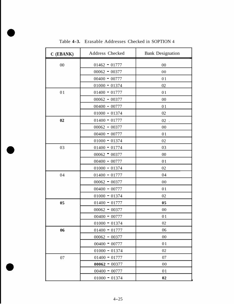
Table 4-3. Erasable Addresses Checked in SOPTION 4
C (EBANK) Bank Designation Address Checked - 00
02 01000 - 01374 0 1 00400 - 00777
00 00062 - 00377 00 01462 - 01777
01 01400 - 01777 01
00062 - 00377 00
00400 - 00777 0 1 01000 - 01374 02
02 02 . 01400 - 01777 00062 - 00377
02 01000 - 01374 01 00400 - 00777
00
03 01400 - 01774 03
00062 - 00377 00
00400 - 00777 02 01000 - 01374 01
04 04 01400 - 01777
00062 - 00377
02 01000 - 01374
01 00400 - 00777
00
05 01400 - 01777 05
00062 - 00377 00
00400 - 00777 02 01000 - 01374 01
06 01400 - 01777 06
00062 - 00377
02 01000 - 01374
01 00400 - 00777
00
07 07 01400 - 01777 00062 - 00377
02 01000 - 01374
01 00400 - 00777
00
L
4-25
BNCHK sets the contents of SKEEP 1 equal to the absolute value of the old contents of SKEEP 1 decremented by 1, and puts the bank number in the 5 low order bits. The bank number is then complemented and added to the contents of SKEEP 1. The result should be -1. The bank number is then incremented and providing the new bank number is less than 22, SKEEP 1 is initialized to zero and the same process is repeated for the next bank. Each bank is checked until bank number 22 is specified, at which time (again assume ROPECHK) control is transferred back to the SELF CHECK lead in to look at SMODE.
The job SHOWSUM is scheduled via the executive NOVAC with a priority of 02 whenever the operator keys in V56 ENTR. (Perform BANKSUM. ) This also sets the content of SMODE to + O which puts the computer in the back-up idle loop whenever SELF CHECK is entered. The job SHOWSUM begins by reserving the DSKY for use in 'the job. Bank 0 is then selected and all words in the bank are added together and the sum stored in SKEEP 1 as in ROPECHK. The difference occurs after the last word has been obtained at which time the subroutine SDISPLAY is performed. SDISPLAY puts the bank number in the 5 low order bits and sets the DSPTABS to flash V05 N01, (display octal comp 1, 2, 3, - specify address). The DSPTABS will then be set to display the bank sum, the bank number, and the bugger word in R1, R2, and R3 respectively. (The bugger word, also known as CKSM, is the last word in each bank. The value of this word is chosen such that when added to all other words in the bank the resulting sum will be equal to, or the com- plement of, the bank number. ) SHOWSUM then goes to sleep to await operator action. If the operator desires to have the next bank displayed he will key in V33 ENTER (proceed without data). This will wake the sleeping job, increment the bank number and, providing the new bank number is less than 22, will obtain and display the information about the next bank. If the bank number is 22, it will be set to zero and the information for bank 0 will be displayed, The cycle will continue as long a s the operator continues to key in V33 ENTER. Job SHOWSUM is terminated by keying in V34 ENTER (terminate). Upon termination of SHOWSUM the computer will not return to the self check option which it was performing when interrupted by V56 ENTER, but will continue in the back-up idle loop. In order to once again enter a meaningful SELF CHECK routine, SMODE must be loaded to the desired option,
I :
SOPTION 6 - This option performs an extensive check of the multiply arithmetic. First, a loop is set up which multiplies 37777 x (37777 through 00001). Each product is checked for accuracy by adding the upper product + lower product + 40000. This will result in a -0 which is then checked. Next, a loop is set up which multiplies -1 x (37777 through 00001). Each product is checked in two ways: 1) the upper product should be equal to -0; 2) the lower product plus the multiplier should also be equal to -0. The next two loops are identical to the first two except the multiplier and multiplicant are interchanged.
In each loop a check is made between every multiply operation to make sure that a job of higher priority is not waiting. A t the end of the last loop, control is transferred back to the SELF CHECK lead into check SMODE.
SOPTION 7 - The divide capability is checked during this option. Several divide opera- tions are made and after each operation the quotient or remainder or both are checked. After passing through the divide loop, the contents of SKEEP 4 are incremented and i f it is still not equal to 0 the loop is repeated. (SKEEP 4 is initialized to 73777. ) When SKEEP 4 becomes 0, register SCOUNT +2 is incremented, after which control is trans- ferred back to SELF CHECK lead in to look at SMODE. SCOUNT +2 will contain the number of times the divide check option has been performed.
4-26
DSKYCHK - If the SMODE register contains k l l the DSKYCHK subroutine will be entered after setting the contents of SMODE to + O . DSKYCHK merely sets the contents of SKEEP 3 to 00012 and schedules the task NXTNMBR on waitlist to be executed in 10 msec. After the delay, task NXTNMBR checks the contents of SKEEP 3 (which was initialized to 00012) and finding a value greater that + O decrements SKEEP 3. DSPTRBS 0 through 10D are then set to display the contents of SKEEP 3 (00011) in decimal (9) in each DSKY digit loca- tion. This task will then reschedule itself (hXTNMBR) in the waitlist to be executed in 5.12 seconds. '5 .12 seconds later NXTNMBR again checks SKEEP 3 , decrements it, sets DSPTABS 0 through 10D to display a decimal eight in each DSKY digit location, and reschedules NXTNMBR on waitlist. The process will continue until the contents of SKEEP 3 = + O . SKEEP 3 will then be set to 01, the VN flash and COMPUTER ACTIVITY lamps will be turned on, and the DSPTABS will be set to display a minus sign in R1, R2, and R3. Al l digits will remain zeros from the previous DSPTAB contents. The next pass will set SKEEP 3 - -0, SKEEP 2 = +1, and display a plus sign in R1, R2, and R3. A l l digits will remain zeros, The next pass will blank each DSKY digit location and the final pass through will turn off the VN flash and COMPUTER ACTIVITY lamps. After DSKY CHK, the computer will remain in the back-up idle loop until SMODE is loaded with a value other than + O .
4-27
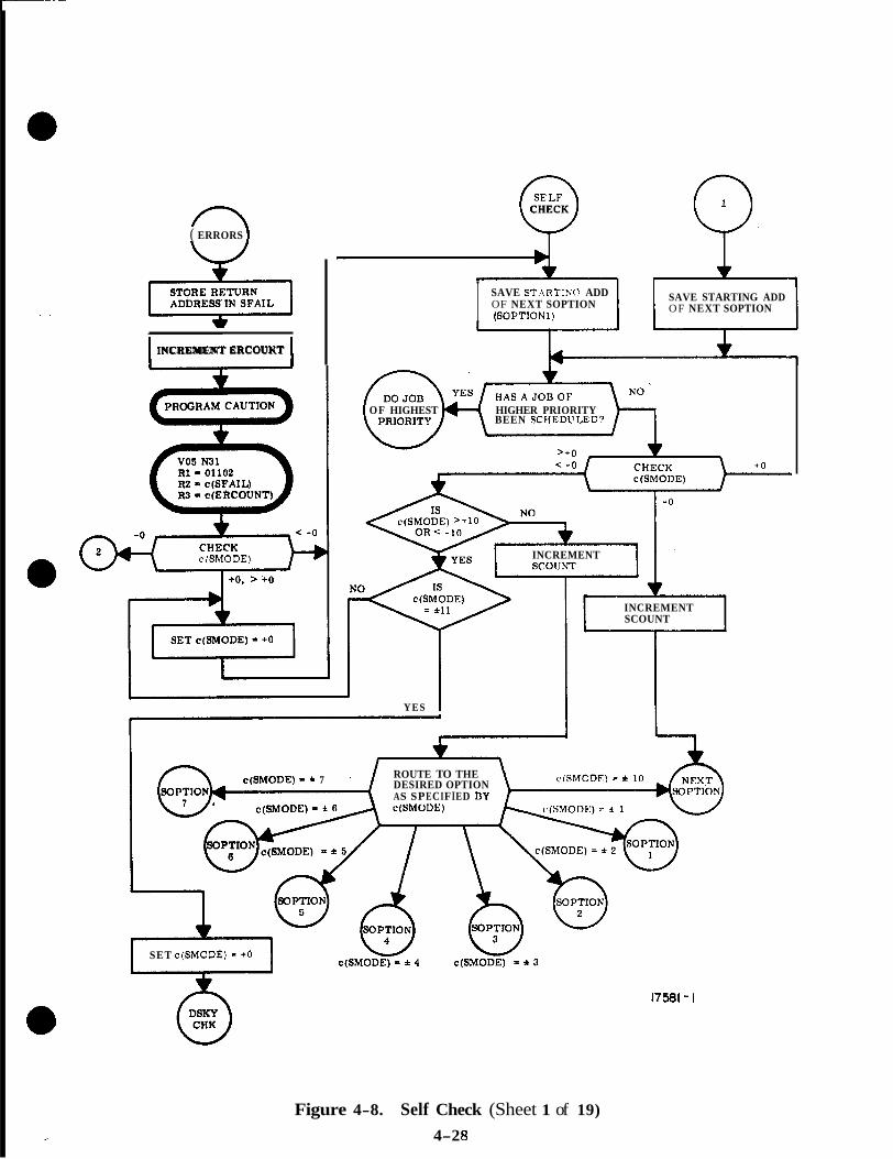
n ( ERRORS 1 LJ
w INCREMENT ERCOUKT
c(SM0DE)
0 CHECK
I SAVE ST.\RTINC, ADD OF NEXT SOPTION (SOPTIONl)
SAVE STARTING ADD OF NEXT SOPTION
L OF HIGHEST HIGHER PRIORITY
BEEN SCHEDL'LED?
INCREMENT
INCREMENT SCOUNT
YES I
c(SM0DE) = * 7 ' ROUTE TO THE DESIRED OPTION cfShfODE) = f IO
AS SPECIFIED ny
SET c(SM0DE) - +O
17581 - I
Figure 4-8. Self Check (Sheet 1 of 19)
4-2 8

A N D T C F E X C E P T T H E ADILIT" T O TC F
CHECK ALL PLILSES 01: CCS E S C E P T RB \\'G. .\LJC! CIIECK: TS E. CS SC, .IN11 I CS E. I
I CHECK APILITY TO R E A l I I CA E. MASF E. S C l ' E, I DCS E. c.!. sc. d t . m DC.? E.
CHECK ABILITY TO RESTORE ,K INTO \ I NSTRUCTIONS l3i\(
E MEMORY. ALSO CIIECK I
I I GOOD I
RETLIRN T O EXIT POINT ;c(SF..\IL); ANI, CONTINUE SELF CHECK. r """- Q
I GOOI'
0 ) I I I
' I 1
I A
17581-2
Figure 4-8. Self Check (Sheet 2 of 19)
4-29

, BAD { FINISH CHECKING PULSES OF MASK
FIMSH CHECKING PULSES
ALSO CHECK ALL PULSES
0
0
0 Q RETURN TO EXIT I POINT [ c(SFA1L) 3 I AND CONTINUE I SELF CHECK
I
' I /i
I I
/ 1 CHECK ALL PULSES OF DCS SC, DXCH SC, AND DCA SC. I
I I I I
CHECKTHATOVERFLOWIS LOST IN PROCESS OF GOING THROUGH L REG. ALSO CHECK THAT Q WILL HOLD
I 16 BITS.
I
I I GOOD
CHECK OVERFLOW, UNDER- FLOW, END-AROUND-CARRY, AND SIGN CHANGE OF ADDER. ALSO CHECK: ADS SC WITH I OVERFLOW) AND TS A'
I CHECK THAT AN INTER- / RUPT DOES NOT OCCIJR \" WHILE OVERFLOW OR UNDERFLOW IS IN THE A REG. ALSO CHECK THAT INHINT AND RELINT WORK
~ ~ """
PROPERLY. I
6 ERRORS
I /
6' SOPTION
I
I J
/
\Figure 4-8. Self Check (Sheet 3 of 19)
4-30
17581 -3

SOPTION \
1
RETURN TO EXIT POINT [ c(SFAfL)] AND CONTINUE SELF CHECK
CHECK ALL WRITE PULSES
GOOD
READ PULSES 1 CHECK ALL I
I I GOOD -1 I
r..cLc /
ROR PULSES I
I GOOD
CHECK ALL WOR PULSES I
'-"' CHECK ALL RAND PULSES
I I GOOD
I
c, 1
/ I BAD< WAND PULSES
CHECK ALL . I GOOD
CHECK ALL RXOR PULSES
0 ERRORS
1 I
I758 1-4 'Figure 4-8. e l f Check (Sheet 4 of 19)
4-3 1

1
I SET c(5KEEP 6 ) - 37777 AND c(SKEEP 7 ) - 40000 I (-5 IS C(SKEEP 6) YES
= 00000
I clSKEEP 7) INCREMENT I I : W E E P 6) -l]+ I t"
CHECK FOR -1
HAS A JOB OF HIGHER PRIORITY BEEN SCHEDULED
IS c(BKEEP a) - 77777
I I I DECREMENT c(8KEEP 6)
17561-5
Figure 4-8. Self Check (Sheet 5 of 19)
4-32
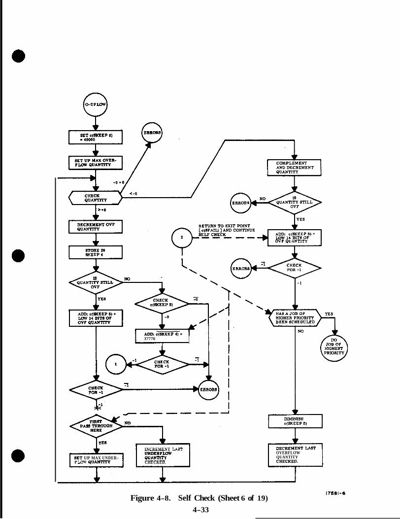
37776 I I
* “““-4
INCREMENT LAST
BET UP MAX UNDER- FLaW Q U A N ” Y CHECKED.
c(SKEEP 6 )
OVERFLOW QUANTITY
Figure 4-8. Self Check (Sheet 6 of 19) 4-33
17861-6

9 I I SET c(EBANK) = 00000.
(EBANK 0 SELECTED. )
3 SET c(SKEEP 7) = 01462.
1
4 01374 BEEN I
SET c(SKEEP 7)
INCREMENT c(SKEEP 7)
b
I .)
0 LOOP
17581-7
Figure 4-8. Self Check (Sheet 7 of 19) 4-34

SAVE CONTENTS OF ADDRESSES X AND X+1. c (x) = CWEEP 711
SET c(X) = X and c (x+ l ) = x+l
1 ADD c(X) TO COMPLEMENT OF c(X+l). CHECK FOR -1.
I' SET c(X) AND C ( x + l ) = x+l
ADD c ( x + l ) TO COMPLEMENT ERROM OF ~(y-). CHECK FOR -1.
0
I RETURN TO EXIT POINT [c(SFAIL)] AND CONTINUE I
I SELF CHECK
I
0 I
RESTORE ORIGINAL CONTENTS & IN ADDRESSES X AND X + l
HAS A JOB OF HIGHER PRIORITY BEEN SCHEDULED
TO BANK BEING CHECKED
17581-8
,Figure 4-8. Self Check (Sheet 8 of 19) 4-35

ADD 00400 TO
IS EBANK 3 SELECTED
n 5 , 6 O R 7
+O CNTR
HAS ADDRESS 01777 BEENCHECKED
BEENCHECKED
HAS ADDRESS 01374 BEENCHECKED
Figure 4-8. Self Check (Sheet 9 of 19) 4-36
17581-9

MISSING PAGE
4-37
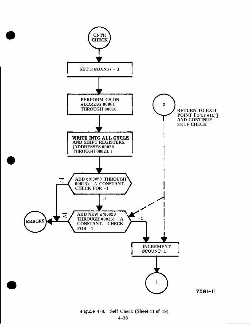
v CHECK
I SET c(EBANK) = 3 I
PERFORM CS ON ADDIiESS 00061
I THROUGH 00010 I
m WRITE INTO ALL CYCLE
I AND SHIFT REGISTERS. (ADDRESSES 00020 THROUGH 00023. ) I 1
ADD ~ ( 0 0 0 2 0 THROUGH 00023) + A CONSTANT. CHECK FOR -1
I -l
0 RETURN TO EXIT POINT c(SFAIL)] AND CONTINUE
I SELF CHECK
I I I I 1
J ADD NEW ~ ( 0 0 0 2 0 \ THROUGH 00025) + A CONSTANT. CHECK FOR -1 I
INCREMENT I SCOUNT+l I
0 17581-1 I
,Figure 4-8. Self Check (Sheet 11 of 19) 4-38
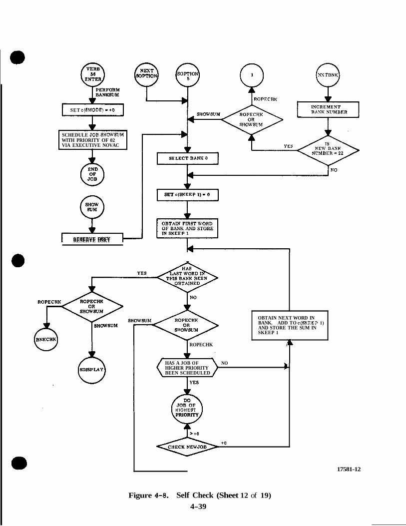
SET c(SM0DE) - t o
WITH PRIORITY OF 02 SCHEDULE JOB.SHOWSUM
VIA EXECUTIVE NOVAC
* RESERVE DSKY
e SET c(SKEEP 1) - 0
OF BANK AND STORE
OBTAIN NEXT WORD IN BANK. ADD TO c(SKEEP 1) AND STORE THE SUM IN SKEEP 1
I ROPECHK A
HAS A JOB OF NO HIGHER PRIORITY B BEEN SCHEDULED
L
JOB OF HIOHEST
t/ PRIORITY
+ O
17581-12
Figure 4-8. Self Check (Sheet 12 of 19) 4-39
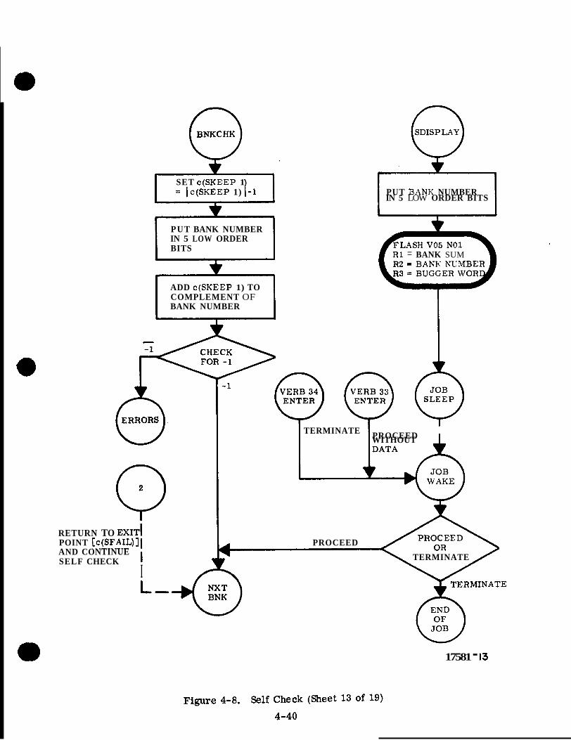
i
SET c(SKEEP 1 = I c(SKEEP 1) 1-1 PUT i3.4NK NUMBER
IN 5 LOW ORDER BITS
PUT BANK NUMBER IN 5 LOW ORDER BITS
R 1 = BANK SUM
ADD c(SKEEP 1) TO COMPLEMENT OF BANK NUMBER
TERMINATE PROCEED I WITHOUT
0 r
RETURN TO EXIT^
I
POINT [c(SFAIL)]I PROCEED AND CONTINUE SELF CHECK I TERMINATE
17581 - 13
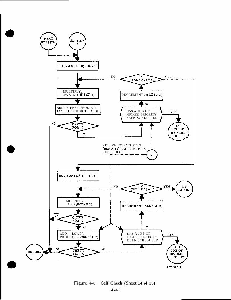
3
01 ERRORS
NO
MULTIPLY: 37'777 X c (SKEEP 2) DECREMENT c (SKEEP 2 )
ADD: U P P E R PRODUCT +
LOIVER PRODUCT +40000 HAS A JOB O F HIGHER PRIORITY BEEN SCHEDPLED
NO
I I I MULTIPLY: I I I 1-1
-1 X c(SKEEP 2) DECREMENT c(SKEEP 2)
I W RETURN TO EXIT POINT [ c ( S F A I L ) ] AND CONTIh'l'E S E L F CHECK
r----- I
ADD: LOWER HAS A J O B OF PRODUCT + c (SKEEP 2) HIGHER PRIORITY
BEEN SCHEDULED
-0
17581-14
Figure 4-8. Self Check (Sheet 14 of 19)
4-41
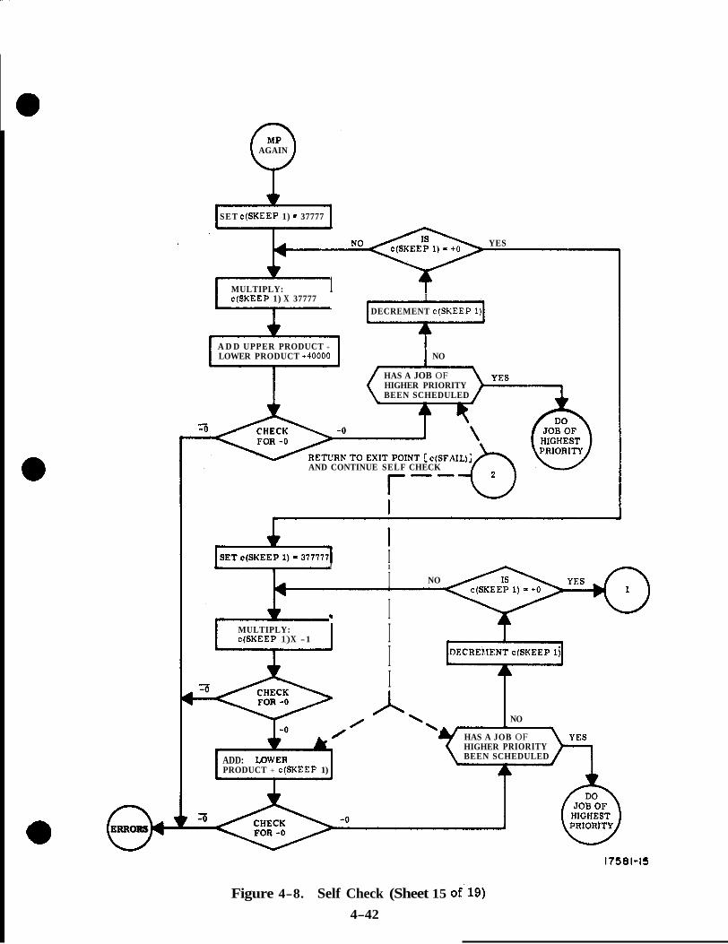
0. ERRORS
AGAIN
SET c(SKEEP 1) - 37777 b I
4 v
YES
MULTIPLY: 1 c(SKEEP 1) X 37777 I
DECREMENT c(SKEEP 1)
A D D UPPER PRODUCT +
LOWER PRODUCT +40000 NO
HAS A JOB OF HIGHER PRIORITY BEEN SCHEDULED
AND CONTINUE SELF CHECK
~
I c I I
4 I NO
.r I I
I I
MULTIPLY: c(SKEEP 1) X -1 I
0 NO
HAS A JOB OF HIGHER PRIORITY BEEN SCHEDULED ADD: XDWER
PRODUCT + c(SKEEP 1)
Figure 4-8. Self Check (Sheet 15 of.19) 4-42
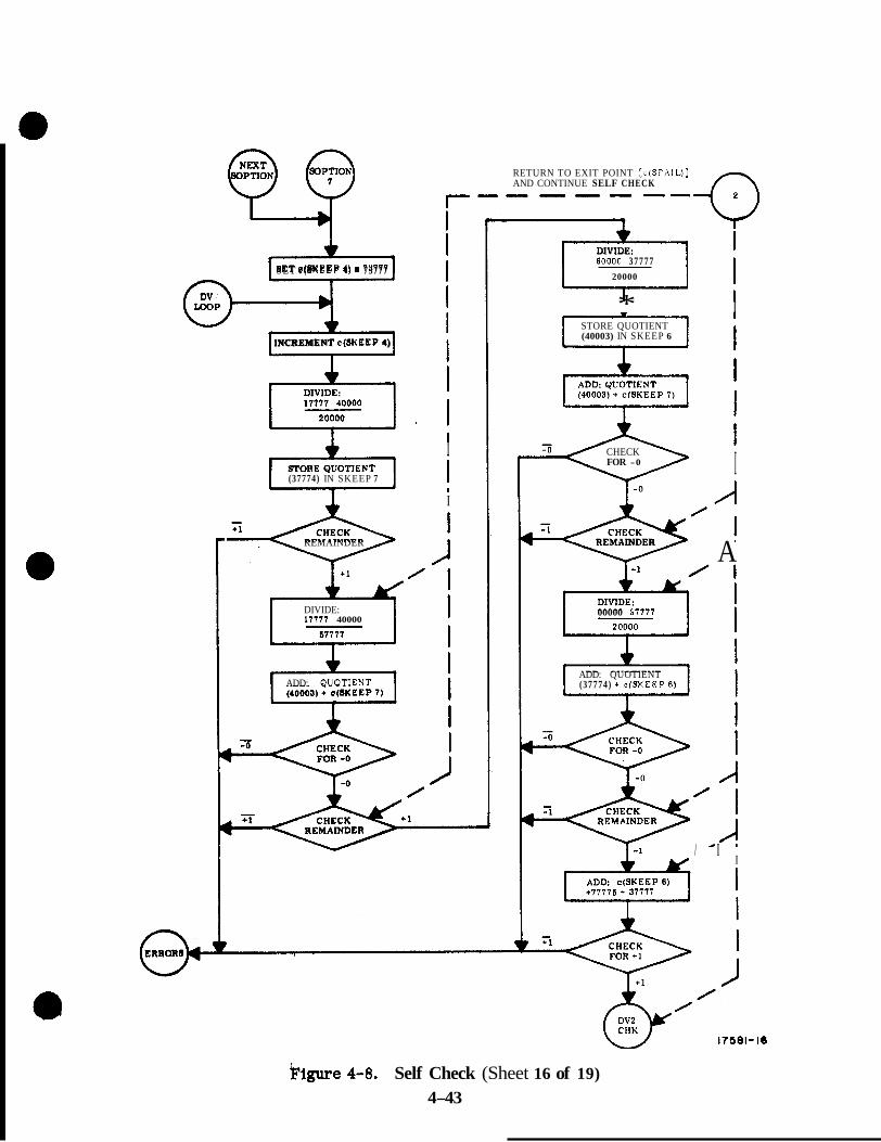
+ SET c(8KEEP 4) - 73777
L - " - J l INCREMENT c(SKEEP 4)
I (37774) IN SKEEP 7
RETURN TO EXIT POINT :cfSFAIL)] AND CONTINUE SELF CHECK """-
I
REMAINDER
DIVIDE: 1'1777 40000
A I ADD: QUOTlENT
A i DIVIDE: 00000 3 7 7 7 7
20000
* I STORE QUOTIENT (40003) IN SKEEP 6
CHECK FOR -0 I
REMAINDER A
00000 57777
ADD: QUOTIENT (37774) + cfSI(EEP 6 )
/ I I
klgure 4-8. Self Check (Sheet 16 of 19) 4-43

0 ERRORS
4 DIVIDE: 17777 20000 37777
ADD: QUOTIENT (37777) + 40000
ADD: REMAINDER (17777) + 67777
0 0
RETURN TO EXIT POINT [c(SFAIL)] AND CONTINUE SELF CHECK r
ADD: REMAINDER (37776) + 40000
I / 1
I I
I I I
0 /
/
DIVIDE: 37776
ADD: COMPLEMENT OF QUOTIENT (40000) + 37776
FOR -1
DIVIDE: 77777 00000
I CJ
/’ I I I
STORE QUOTIENT (37777) IN SKEEP 7
DIVIDE: 77777 00000
77771 I I I
STORE QUOTIENT (40000) IN SKEEP 6
A I ADD: QUOTIENT (40000) + c(SKEEP 7)
I FOR -0 I
/
CHECK REMAINDER &’
I I
/
17581 -17
IFigure 4-8. Self Check (Sheet 17 of 19) 4-44
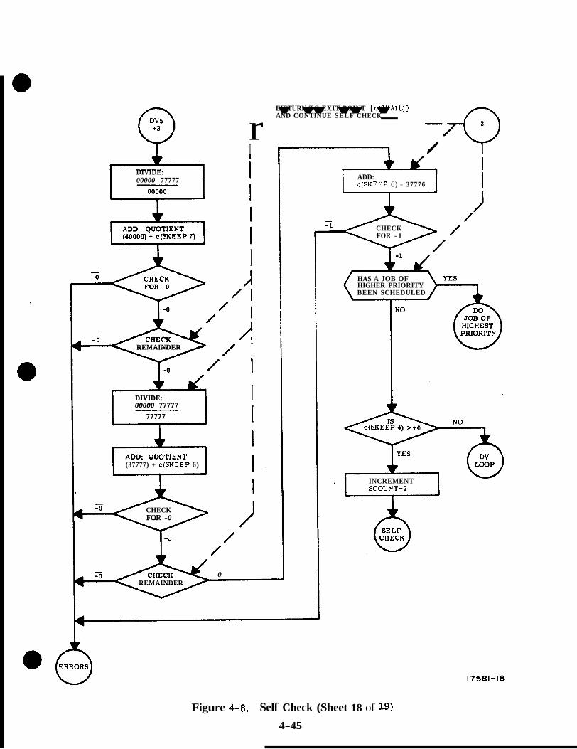
DIVIDE: 00000 77777
r I
EIETURN TO EXIT POINT [ c(SFAIL)] AND CONTINUE SELF CHECK
I /I
/ I
/ I
/ I
/ / J REMAINDER
/ I
I DIVIDE: I 00000 77777
77777 I
*
/ I
/
DIVIDE: I 00000 77777
77777 I I
*
(37777) + c(SKEEP 6)
CHECK FOR -0
/ /
REMAINDER -0
"""- -Q /
c(SKEEP 6) + 37776 ADD:
I
CHECK FOR -1
HAS A JOB OF HIGHER PRIORITY BEEN SCHEDULED
INCREMENT SCOUNT+P
Figure 4-8. Self Check (Sheet 18 of 19)
4-45

SET c(SKEEP 3) - 00012
"NXTNMBR" ON WAIT- SCHEDULE TASK
LIST TO BE EXECUTED IN 10 MS
I
CHECK > t o c(SKEEP 3)
+ O
I CHECK > t o
c(SKEEP 3)
+ O
SET c(SKEEP 3) SET c(SKEEP 3) c(SKEEP 3) DECREMENT 1 I
I I
I = 00001 I SET c(SKEEP 2) SET c(SKEEP 2) = 00001
SET DSPTABS 1, 4 , AND 6 TO DISPLAY PLUS SIGN IN R1, R2, AND R3. (DIGITS WILL
DSPTAB CONTENTS FROM PREVIOUS REMAJN r?LL ZEROS
TURN OFF VN FLASH AND COMPUTER ACTIVITY LAMPS *
I I SET c(SKEEP 2) - 00000
SET DSPTABS 0 THROUGH
DSKY DIGIT LOCATION 10D TO BLANK EACH
v
.
AND COMPUTER
AND 5 TO DISPLAY MINUS SIGN IN R1.
WILL REMAIN ALL R2, AND R3. (DIGITS
ZEROS FROM PREVIOUS DSPTAB CONTENTS
* SET DSPTABS 0 THROUGH 10D TO DISPLAY c(SKEEP 3)
DSKY DIGIT LOCATION IN DECIMAL IN EACH
* SET DSPTABS 0 THROUGH 10D TO DISPLAY c(SKEEP 3)
DSKY DIGIT LOCATION IN DECIMAL IN EACH
4
"NXTNMBR" ON WAIT- SCHEDULE TASK
IN 5 . 1 2 SECONDS LIST TO BE EXECUTED
17581-19
\Figure 4-8. Self Check (Sheet 19 of 19) 4-46
APPENDIX A
COMPUTER PROGRAMS
A. 1 DESCRIPTION OF COMPUTER INSTRUCTIONS
Instructions, which are directions given to perform specific operations, are the same for CMC and LGC. Together with data addresses, they constitute the building blocks of a program. Programs are sequential lists of instruction words. There are two general categories of inetructions, machine and interpretive. Several types of instructions used In the LGC may be categorized as follows:
MACHINE (56)
REGULAR (42)
BASIC (15)
EXTRACODE (12)
CHANNEL (7)
SPECIAL (8)
INVOLUNTARY (9)
INTERRUPT (2)
COUNTER (7)
PERIPHERA L (5)
INTERPRETIVE
The machine instructions can be interpreted and executed directly by using the sequence generator to control the LGC operation. The interpretive instructions are a programmer's convenience and must be interpreted under program control, converted to machine instruc- tions and then executed as machine instructions. Table A-1 lists the machine instructions alphabetically and gives a brief description of each. The reader will find it to his advantage to refer back to this table once he has gained a greater familiarity with the LGC. The following symbols a re used in table A-1,
K represents any address in the central processor, erasable memory o r fixed memory.
F represents an address in fixed memory only.
0 E represents an address in the central processor or erasable memory.
H represents any channel address.
A- 1

C represents any counter address.
A represents the A register on the central processor.
L represents the L register in the central processor.
c(K) represents the contents of K, i. e . , the data located in address K.
1, I + 1, I + 2 represents the addresses of successive instruction words stored in memory.
c (I), C (I + l), C (I + 2) represents the contents of successive instruction words stored in memory.
A. 1 .1 MACHINE INSTRUCTIONS. The LGC has three classes of machine instructions: regular, involuntary, and peripheral. Regular instructions are programmed and a re executed in whatever sequence they have been stored in memory. Involuntary instruc- tions (with one exception) are not programmable and have priority over regular instruc- tions: no regular instruction can be executed when the LGC forces the execution of an involuntary instruction. The peripheral instructions are used during ground testing when the LGC is connected to the CTS o r PAC: the LGC cannot perform any program operation during a peripheral instruction.
A. 1.2 REGULAR INSTRUCTIONS. There a re four types of regular instructions: basic, channel, extracode, and special. The difference between the regular instructions is directly related to the way in which the LGC interprets an instruction word. Instruction words stored in memory are called "basic instructions words" and consist of a three bit order code and a twelve bit address code. The order code defines an operation and the address code defines a location.
The contents of the SQ register will determine what instruction the LGC will perform. The SQ register reflects that data transferred into it from memory. The SQ register consists of six bits and an EXTend bit (figure A-l )* A binary point is assumed to be located between bits thlrteen and twelve. When an instruction word is transferred from memory to the SQ register, bfts 15 through 10 of the word in memory are transferred to bits 16 and 14 through 10 of the SQ register (figure A-2). In the following paragraph, however, only the transfer of bits 15, 14 and 13 from memory to bits 16, 14 and 13 of the SQ register will be considered.
*\ BINARY POINT
Figure A-1. SQ Register
A-2

Table A-1. Machine Instructions, Alphabetical Listing (Sheet 1 of 8)
Symbolic Instruction Word
AD K
ADS E
LUG E
BZF F
BZMF F
CA K
Order Code
, 06.
02.6
12.4
11.2 11.4 11.6
16.2 16.4 16.6
03.
Description
Basic Instruction: add c(K) to c(A); stores result in A; takes next instruction from I + 1 where I is location of AD K.
Basic Instruction: ad&, c(A) to c(E) and stores result in both A and E; takes next instruction from I + 1 where I is location of ADS E.
Extra Code Instruction: adds +1 to c(E), if c(E) is posltlve and -1 if c(E) is negative; stores result in E; takes next lnstructfon from I + 1 where I is location of AUG E.
NOTE: AUG, DIM and INCR are slightly . modified counter increment sequences.
Accordingly, if one of this group over- flows when addressing a counter for which overflow (during involuntary increment- ing) is supposed to cause an interrupt, the interrupt will occur. It should be noted that all three of these instructions unlike the increment sequences, always operate in one's complement, even when address- ing CDU counters,
Extra Code Instruction: takes next instruc- tion from F if c(A) is a; otherwise takes next instruction from I' + 1 where I is location of BZF F.
Extra Code Instruction: takes next instruc- tion from F if c(A) is +O o r negative; other- wise takes next instruction from I + 1 where I is location of BZMF F.
Basic Instruction: clears c(A) and copies c(K) into A; takes next instruction from I + 1 where I is location of CA K.
Execution Time in MCTls
2
2
2
1 if c(A) is a; otherwise 2
1 i f c(A) is +O or negative, otherwise 2
2
A-3
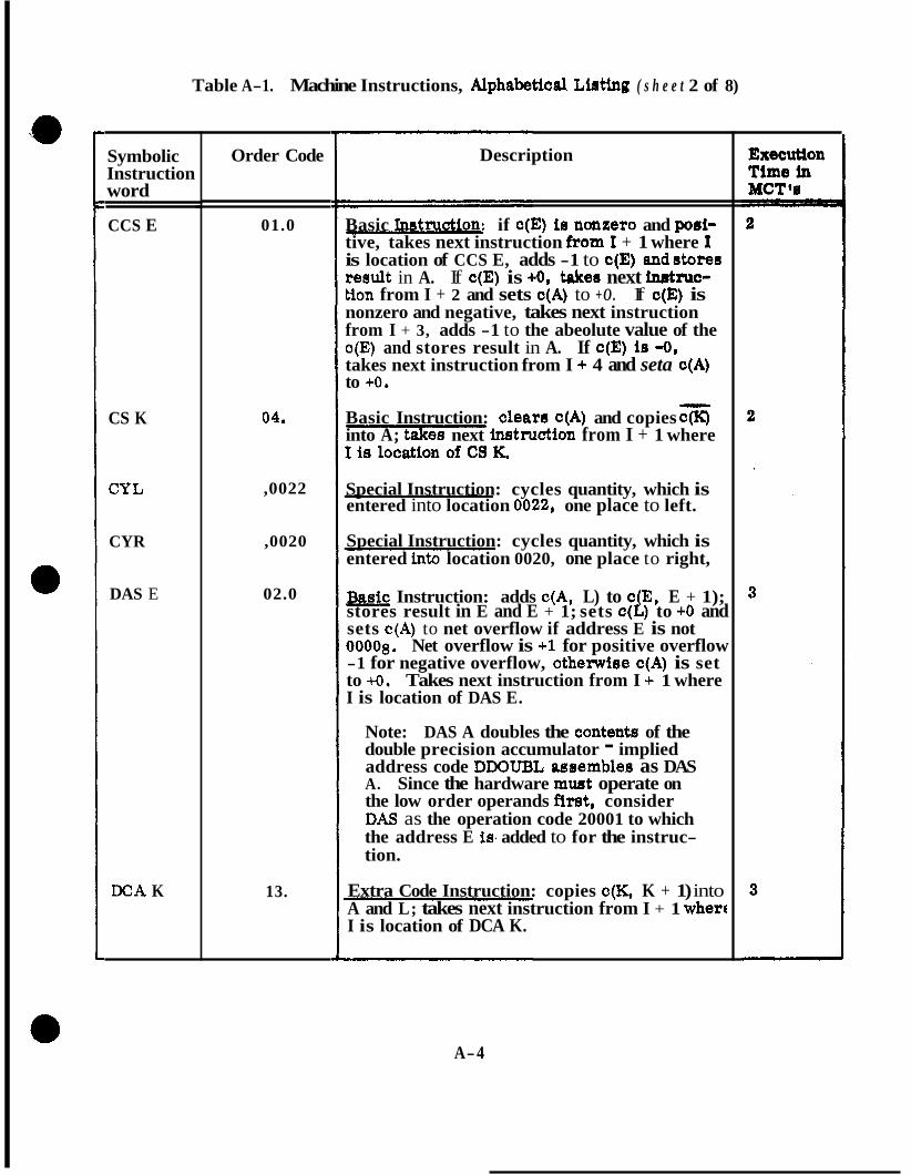
Table A-1. Machine Instructions, Alphabetical Lirrrting ( s h e e t 2 of 8)
Symbolic Instruction word
CCS E
CS K
CYL
CYR
DAS E
DCA K
Order Code
01.0
04.
,0022
,0020
02.0
13.
Description
Basic instruction: if c(E) is ncmzero and p o i - tive, takes next instruction €torn I + 1 where I is location of CCS E, adds -1 to c(E) andstoree result in A. If c(E) is +Os take0 next inutruc- tion from I + 2 and sets c(A) to +O. If c(E) is nonzero and negative, takes next instruction from I + 3, adds -1 to the abeolute value of the c(E) and stores result in A. If c(E) ie -0, takes next instruction from I + 4 and seta c(A) to +o. Basic Instruction: cleara c(A) and copies cCK) into A; take8 next instruction from I + 1 where
Special Instruction: cycles quantity, which is entered into location 0022, one place to left.
Special Instruction: cycles quantity, which is entered into location 0020, one place to right,
-sic Instruction: adds c(A, L) to c(E, E + 1); stores result in E and E + 1; sets c(L) to +O and sets c(A) to net overflow if address E is not 00008. Net overflow is +1 for positive overflow -1 for negative overflow, othelwiee c(A) is set to +O. Takes next instruction from I -c 1 where I is location of DAS E.
Note: DAS A doubles the content6 of the double precision accumulator - implied address code DDOUBL asaemblee as DAS A. Since the hardware mwt operate on the low order operands first, consider D M as the operation code 20001 to which the address E is, added to for the instruc- tion.
Extra Code Instruction: copies c(K, K + 1) into A and L; takes next instruction from I + 1 wherc I is location of DCA K.
A-4
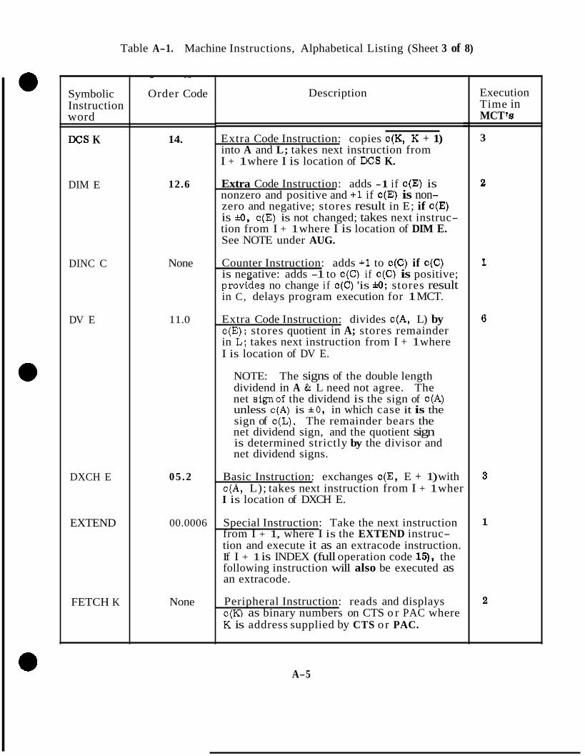
Table A-1. Machine Instructions, Alphabetical Listing (Sheet 3 of 8)
Symbolic Instruction word
DCS K
DIM E
DINC C
DV E
DXCH E
EXTEND
FETCH K
~ ~~
Order Code
14.
12.6
None
11.0
05.2
00.0006
None
Description
Extra Code Instruction: copies c(K, K + 1) into A and L; takes next instruction from I + 1 where I is location of DCS K.
Extra Code Instruction: adds -1 if c(E) is nonzero and positive and +1 if c(E) is non- zero and negative; stores result in E; if c(E) is a, c(E) is not changed; takes next instruc- tion from I + 1 where I is location of DIM E. See NOTE under AUG.
Counter Instruction: adds +1 to c(C) if c(C) is negative: adds -1 to c(C) if c(C) is positive; provildes no change if c(C) 'is & O m ; stores result in C, delays program execution for 1 MCT.
Extra Code Instruction: divides c(A, L) by c(E); stores quotient in A; stores remainder in L; takes next instruction from I + 1 where I is location of DV E.
NOTE: The signs of the double length dividend in A & L need not agree. The net signof the dividend is the sign of c(A) unless c(A) is ~ 0 , in which case it is the sign of c(L). The remainder bears the net dividend sign, and the quotient sign is determined strictly by the divisor and net dividend signs.
Basic Instruction: exchanges c(E, E + 1) with c(A, L); takes next instruction from I + 1 wher I is location of DXCH E.
Special Instruction: Take the next instruction from I + 1, where I is the EXTEND instruc- tion and execute it as an extracode instruction. If I + 1 is INDEX (full operation code 14, the following instruction will also be executed as an extracode.
Peripheral Instruction: reads and displays c(K) as binary numbers on CTS o r PAC where K' is address supplied by CTS or PAC.
Execution Time in MCT '8
3
A-5

Table A-1. Machine Instructions, Alphabetical Listing (Sheet 4 Of 8)
-
3 y m bo1 ic hstruction Word
EDOP
COJ
[NCR E
INHINT
INOT LD H
INOTRD H
LXCH E
MCDU C
Order Code
.0023
00.
02.4
00.0004
None
None
02.2
None
~
Description
9ecia.l Instruction: shifts quantity, which .S entered into location 0023, seven places ;o left.
hterrupting Instruction: transfers control ;o instruction stored in location 40008 and ?roceeds from there.
Basic Instruction: adds + 1 to c(E); Stores result in E ; takes next inStr'UCtiOn from f + 1 where I is location of INCR E. See NOTE under AUG.
Special Instruction: Inhibit program interrupts until a subsequent RELINT.. Take the next instruction from I + 1 where I was INHINT.
NOTE: The inhibition set by INHINT and removed by RELINT in entirely inde- pendent of the one set by an interrupt and removed by a RESUME.
Peripheral Instruction: loads data supplied by CTS or PAC into location H where H is chan- nel -address also supplied by CTS o r PAC.
Peripheral.Instruction: reads and displays c(H) as binary number on CTS or PAC where H' is channel kddress supplied by CTS o r PAC.
Basic Instruction: exchanges c(E) with c(L); takes next instruction from I + 1 where I is location of LXCH E.
Counter Instruction: adds -1 (two's comple- ment) to c(C). NOTE: Incrementing in two's complement modulator notation transfers octal 40000 to 37777 and 00000 to 77777 and is other- wise like one's complement. PCDU and MCDU replace PINC and MINC for counters 0032 through 0036.
Execution Time in MCT's
2
2
1
1
1
2
1
A-6
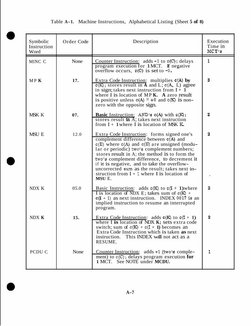
Table A-1. Machine Instructions, Alphabetical Listing (Sheet 5 of 8)
Symbolic Instruction Word
MINC C
M P K
MSK K
MSU E
NDX K
NDX K
PCDU C
Order Code
None
17.
07.
12.0
05.0
15.
None
Description
Counter Instruction: adds -1 to c(C); delays program execution for 1 MCT. If negative overflow occurs, C(C) is set to -0.
-
Extra Code Instruction: multiplies c(A) by c(K); stores result in A and L; c(A, L) agree in sign; takes next instruction from I + 1 where I is location of M P K. A zero result is positive unless c(A) = * O and c(K) is non- zero with the opposite sign.
Basic Instruction: AND's c(A) with c(K); stores result in A; takes next instruction from I + 1 where I is location of MSK K.
Extra Code Instruction: forms signed one's complement difference between c(A) and c(E) where c(A) and c(E) a r e unsigned (modu- lar o r periodic) two's complement numbers; stores result in A; the method is to form the two's complement difference, to decrement it i f it is negative, and to take the overflow- uncorrected sum. as the result; takes next in- struction from I + 1 where I is location of MSU E.
Basic Instruction: adds c(K) to c(I + 1) where I is location of NDX E; takes sum of c(K) + C(I + 1) as next instruction. INDEX 0O1i is an implied instruction to resume an interrupted program.
Extra Code Instruction: adds c(K) to c(I + 1) where I is location of NDX K; sets extra code switch; sum of c(K) + c(I + 1) becomes an Extra Code Instruction which is taken as next instruction. This INDEX will not act as a RESUME.
Counter Instruction: adds +1 (two's comple- ment) to c(C); delays program execution for 1 MCT. See NOTE under MCDU.
Execution Time in MCT's
A-7
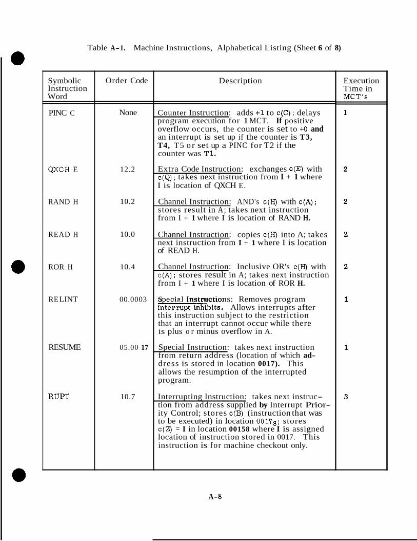
Table A-1. Machine Instructions, Alphabetical Listing (Sheet 6 of 8)
Symbolic Instruction Word
PINC C
QXCH E
RAND H
READ H
ROR H
RE LINT
RESUME
RUFT
Order Code
None
12.2
10.2
10.0
10.4
00.0003
05.00 17
10.7
Description
Counter Instruction: adds +1 to c(C); delays program execution for 1 MCT. If positive overflow occurs, the counter is set to +O and an interrupt is set up if the counter is T3, T4, T5 o r set up a PINC for T2 if the counter was T1.
Extra Code Instruction: exchanges c(E) with c(&); takes next instruction from I + 1 where I is location of QXCH E.
Channel Instruction: AND's c(H) with c(A); stores result in A; takes next instruction from I + 1 where I is location of RAND H.
Channel Instruction: copies c(H) into A; takes next instruction from I + 1 where I is location of READ H.
Channel Instruction: Inclusive OR's c(H) with c(A) ; stores result in A; takes next instruction from I + 1 where I is location of ROR H.
S ecia.1 Instructions: Removes program -bits. Allows interrupts after this instruction subject to the restriction that an interrupt cannot occur while there is plus o r minus overflow in A.
Special Instruction: takes next instruction from return address (location of which ad- dress is stored in location 0017). This allows the resumption of the interrupted program.
Interrupting Instruction: takes next instruc- tion from address supplied by Interrupt Prior- ity Control; stores c(B) (instruction that was to be executed) in location 00178; stores c(Z) = I in location 00158 where I is assigned location of instruction stored in 0017. This instruction is for machine checkout only.
Execution Time in MCT's
A- 8
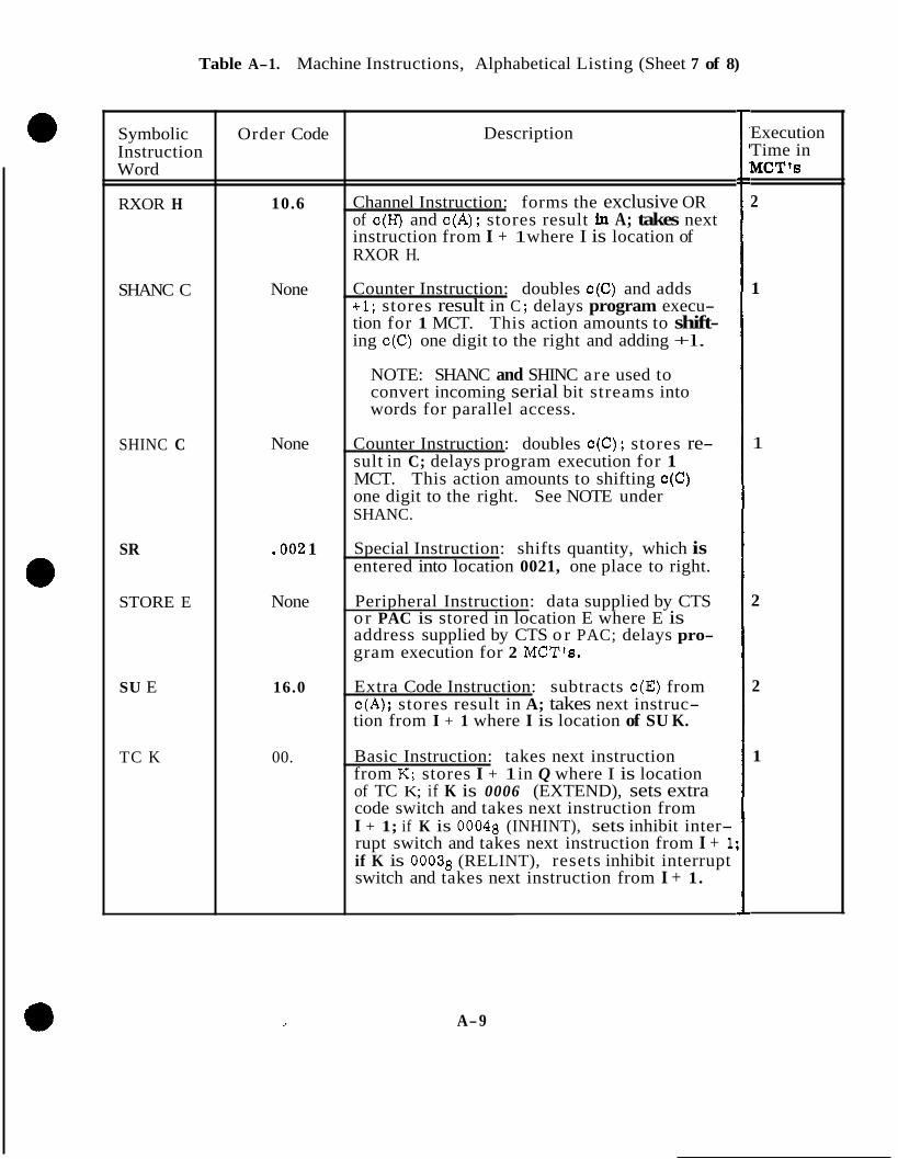
Table A-1. Machine Instructions, Alphabetical Listing (Sheet 7 of 8)
Symbolic Instruction Word
RXOR H
SHANC C
SHINC C
SR
STORE E
SU E
TC K
Order Code
10.6
None
None
.002 1
None
16.0
00.
Description
Channel Instruction: forms the exclusive OR of c(H) and c(A); stores result in A; takes next instruction from I + 1 where I is location of RXOR H.
Counter Instruction: doubles c(C) and adds +1; stores result in C ; delays program execu- tion for 1 MCT. This action amounts to shift- ing c(C) one digit to the right and adding +l.
NOTE: SHANC and SHINC are used to convert incoming serial bit streams into words for parallel access.
Counter Instruction: doubles c(C); stores re- sult in C; delays program execution for 1 MCT. This action amounts to shifting c(C) one digit to the right. See NOTE under SHANC.
Special Instruction: shifts quantity, which is entered into location 0021, one place to right.
Peripheral Instruction: data supplied by CTS or PAC is stored in location E where E is address supplied by CTS o r PAC; delays pro- gram execution for 2 MCT'e.
Extra Code Instruction: subtracts c(E) from c(A); stores result in A; takes next instruc- tion from I + 1 where I is location of SU K.
Basic Instruction: takes next instruction from K; stores I + 1 in Q where I is location of TC K; if K is 0006 (EXTEND), sets extra code switch and takes next instruction from I + 1; if K is 00048 (INHINT), sets inhibit inter- rupt switch and takes next instruction from I + 1: if K is 00038 (RELINT), resets inhibit interrupt switch and takes next instruction from I + 1.
Execution Time in MCT's
2
1
1
2
2
1
A-9
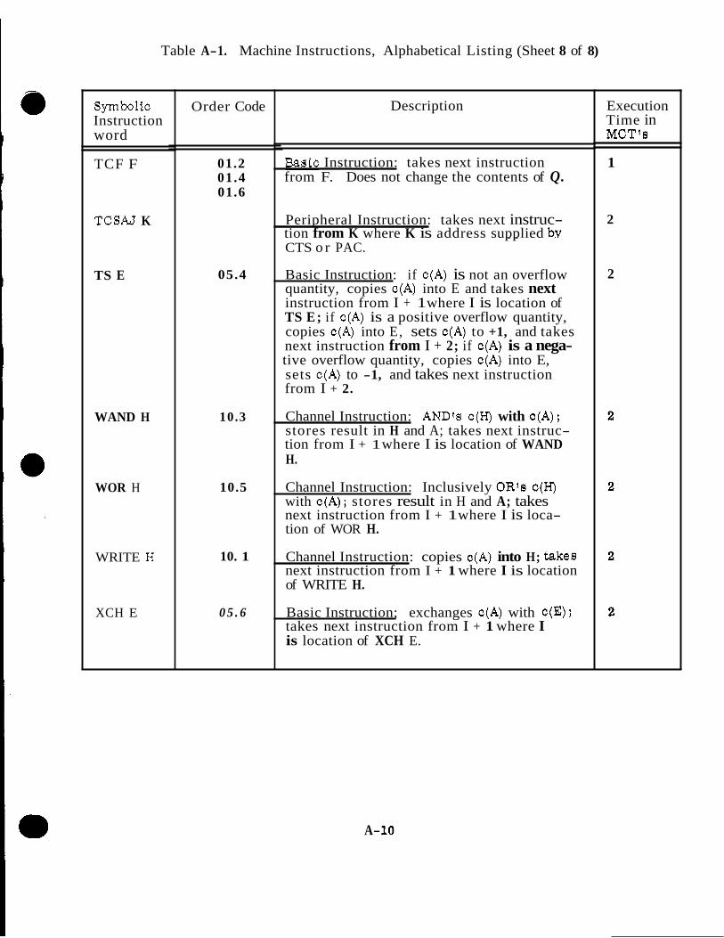
Table A-1. Machine Instructions, Alphabetical Listing (Sheet 8 of 8)
Symbolic Instruction word
TCF F
TCSAJ K
TS E
WAND H
WOR H
WRITE H
XCH E
Order Code
01.2 01.4 01.6
05.4
10.3
10.5
10. 1
0 5 . 6
Description
pasic Instruction: takes next instruction from F. Does not change the contents of Q.
Peripheral Instruction: takes next instruc- tion from K where K is address supplied by CTS o r PAC.
"
Basic Instruction: if c(A) is not an overflow quantity, copies c(A) into E and takes next instruction from I + 1 where I is location of TS E; if c(A) is a positive overflow quantity, copies c(A) into E, sets c(A) to +1, and takes next instruction from I + 2; if c(A) is a nega- tive overflow quantity, copies c(A) into E, sets c(A) to -1, and takes next instruction from I + 2.
Channel Instruction: ANDts c(H) with c(A); stores result in H and A; takes next instruc- tion from I + 1 where I is location of WAND H.
Channel Instruction: Inclusively OR's c(H) with c(A); stores result in H and A; takes next instruction from I + 1 where I is loca- tion of WOR H.
Channel Instruction: copies c(A) into H; takes next instruction from I + 1 where I is location of WRITE H.
Basic Instruction; exchanges c(A) with c(E); takes next instruction from I + 1 where I is location of XCH E.
Execution Time in MCTts
1
2
2
A- 10

I I I I l I I I I l I l , INSTRUC- TION WORD IN MEMORY
v v v v v v 16 14 13 12 11 10
PROGRAM ACTION
SQ REGISTER
Figure A-2. Memory to SQ Register Transfer
The three bit order code in the memory basic instruction words has a capability of uniquely deflning eight operations: To increase the number of operations defined by the SQ register, bit EXT (extend) is made a 1 o r 0 under program control, therefore, bits EXT, 16, 14 and 13 of the SQ register define sixteen operations.
Note the order codes in column 2 of table A-1. These order codes are determined, in most cases, by the contents of the SQ register. Figure A-3 shows how the order codes in table A- 1 are related to the actual contents of the SQ register. The order code defined by figure A-3 is TS E.
In table A-1, the instructions can be categorized into three distinct groups by their listings in the order code column.
a. Those that list 'fNone.fl
b. Those that list four digits to the right of the binary point.
C. Those that list two o r three digits with the binary point written to the right of the second digit.
Group a contains the counter and peripheral instructions. There are no order codes associated with these instructions.
Group b contains the special instructions that are address dependent basic instructions. Their order codes are, in part, determined by bits 1 through 12. Those special instruc- tions with no digits to the left of the decimal point can be combined with any basic instruction order code. Those with digits to the left of the decimal point are combined with that basic instruction whose order code appears to the right of the decimal point.
Group c contains the basic, extracode and channel instructions, i. e., all the regular instructions with the exception of the special instructions. Also included in this group a re the two interrupt instructions; these are regular instructions.
A-11.

Note that the instructions in this group may or may not have a digit to the right of the decimal point. When there is a digit to the right of the decimal point, it is determined by bits 11 and 12 or bits 10, 11 and 12 of the SQ register. When bits 11 and 12 are necessary to extend the order code field, their configuration is called a "quarter code." When bits 10, 11 and 12 a r e necessary to extend the order code field, their configuration is called an "eighth code. 11 Table A-2 shows the configuration of the various quarter and eighth codes associated with this group. Note that there are two ways of defining a zero o r an even digit to the right of the decimal point. Observe instructions CCS E and TCF F in table A-1. These instructions a re identical if only the digits to the left of the decimal point are considered. There, two instructions can be distinguished, however, if bits 11 and 12 of the SQ register a r e observed. Note that the c~n ten t of bit 10 in register SQ is irrelevant because only four cases have to be distinguished and, conse- quently, a quarter code is sufficient to define the necessary operation. Now observe the instruction in table A-2 which have digits 1 and 0 to the left of the decimal point in the order code column. There a re eight of these instructions and to differentiate between them, bits 10, 11 and 12 of the S Q register a r e necessary because eight cases must be differentiated. If just bits 11 and 12 were used, only four cases could be distinguished.
16 14 13 12 11 10
1 CONTENTS OF SQ REGISTER X 0 1 1 0
u u 0 5 4
X SIGNIFIES A 1 OR 0
Figure A-3. Order Code Determination
Basic instructions can be differentiated from extracode and channel instructions by the left hand digit of the order code, If bit EXT in the SQ register is a 0 , then the left hand digit is a zero and the instruction is a basic instruction. If bit EXT is a 1, then the left hand digit is a one and the instruction is an extracode or channel instruction.
A. 1.3 INVOLUNTARY INSTRUCTIONS. The involuntary instruction class contains two types of instructions - interrupt and counter. The interrupt instructions use the basic instruction word format just as the regular instructions do. However, the interrupt instructions ace not entirely programmable, The contents of the order code field and the address field a re supplied by computer logic rather than the program. The counter instructions have no instruction word format. Signals which function as a decoded order code specify the counter instruction to be executed and the computer logic supplies the address. The address for these instructions is limited to one of 29 counter locations in memory.
There a r e two interrupt instructions. One instruction initializes the computer when power is first applied and when certain program traps occur. The other interrupt instruction is executed at regular intervals to indicate time, receipt of new telemetry o r keyboard data, o r transmission of data by the computer. This interrupt instruction may be programmed to test the complter. \
A- 12

I EIGHTH OR QUARTER CODES I t
EIGHTH
QUARTER
EIGHTH
EIGHTH
QUARTER
EIGHTH
EIGHTH
QUARTER
EIGHTH
EIGHTH
QUARTER
EIGHTH
a 0
00
01
* 2
. 2
03
. 4
, 4
. 5
. 6
. 6
. 7
SQ REGISTER BITS
12
0
0
0
0
0
0
1
1
1
1
1
1
- 11
0
0
0
1
1
1
0
0
0
1
1
1
-
-
- 10
0
X
1
0
X
1
0
X
1
0
X
1
-
- X stands for a 1 or 0
Table A-2. Quarter and Eighth Codes
There a re several counter instructions. Two instructions will either increment o r decrement by one the content of a counter location using the one's complement number system, Two other instructions perform the same function using the two's complement number system. Certain counter instructions control output rate signals and convert serial telemetry data to parallel computer data.
A. 1.4 PERIPHERAL INSTRUCTIONS. There are two types of peripheral instructions. One type deals with memory locations and the other type deals with channel locations. The peripheral instructions are not used when the computer is in the spacecraft. They a r e used when the computer is connected to peripheral equipment during subsystem and preinstallation system testing. The peripheral instructions are not programmable and a r e executed when all computer program operations have been forcibly stopped. These instructions are used to read and load any memory or channel location and to start the computer program at any specified address. The peripheral instructions and counter instructions are processed identically.
A- 13
A. 1.5 INSTRUCTION DATA FLOW. Examples of the instruction data flow are illus- trated on the subinstruction flow charts ADO, STD2, RSM3, and NDXO, figures A-4, A-5, A-6 and A-'7,
A. 1.6 INTERPRETIVE INSTRUCTIONS. Interpretive instructions, a programmer's convenience and a means of saving memory storage area, must be interpreted under program control, converted to machine instructions and then executed as machine instructions. The coding into interpretive instructions of routines which contain double precision, triple precision, vector, and vector matrix operations results in a con- siderable saving in program storage area in fixed memory. This saving is achieved at the expense of computer operating speed; however, when operating in basic machine language the computer operates much faster than the equipment with which it interfaces. Since most of the PGNCS problems the computer i s required t;, solve involve complex mathematical equations, the use of interpretive instructions for vector matrix algebra and complex differential calculus is a definite asset. Interpretive instructlone are shown in table A-3.
A- 14

F U t CY 025252 I
I I I I I
4 25252
CW
S I213 ws 4 oca0
I I
I
a oco1213 W G 000000 4 02.5252 4 t R G f
I W G 021252 6 025252
I J I
0 O C O l Z l 3 W O 025252 urn 116 025252
I I I
r
4
RSC 1 L
O O O l O i nsc 1 WI C25354
a RSI: + I
I I Z O C 0 6 C O R S C 6 R Z ooocco I
I ! 1
U RL, LC25154 000660
'I 000657 WV*025252
X 000000 A2X 0000102
CI I 0
iTAGE : O U N T E R 5 S E T
RSC IS I N M l l l l T E D BY ADDRESS
ro ooo 1213 INS
F I X E D ST2 SETS MEMORY STAGE STROBE IS COUNTER INMIBITED TO 010 BY ADDRESS 1213 I N S
Figure A-4. Subinstruction ADO, Data Transfer Diagram
A- 15
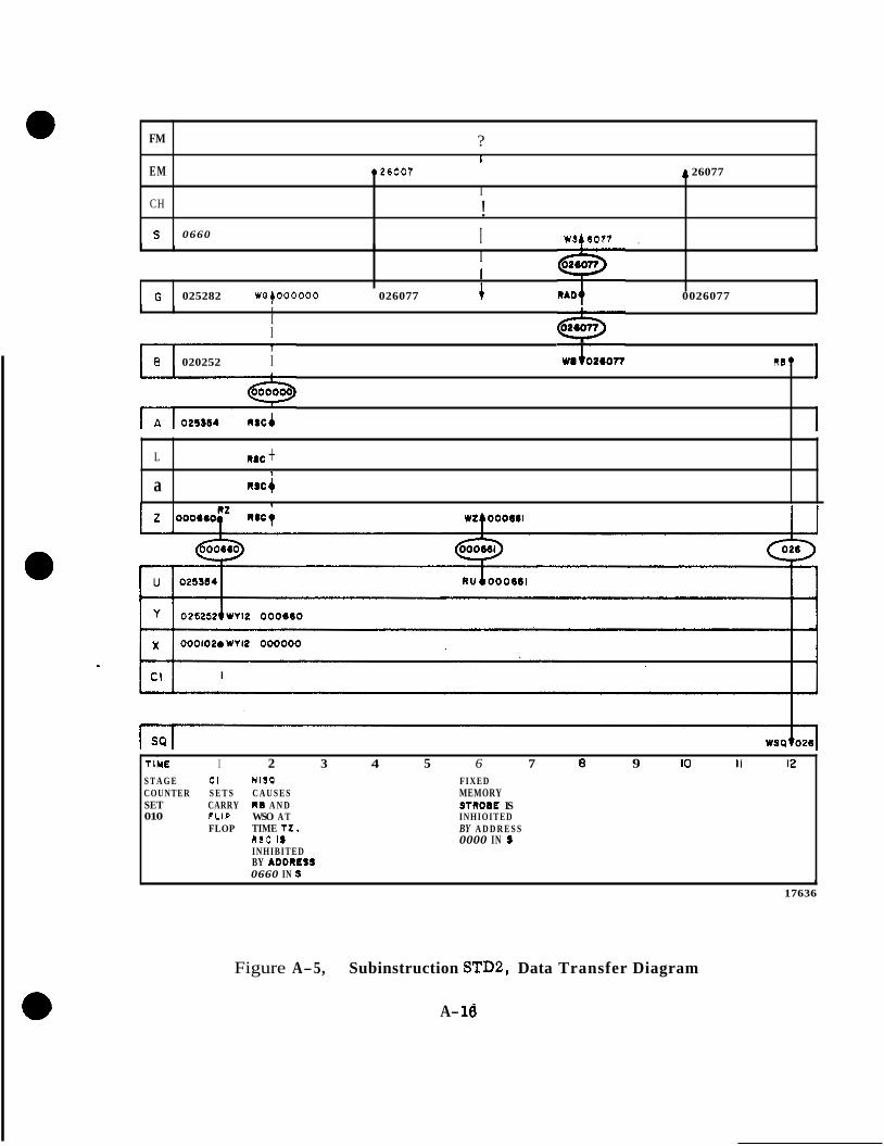
FM ?
028007 A 26077 EM 1
I CH !
I WSt6077 , S 0660
I 1 J I
I 1
G 025282 W G ~ O O O O O O 026077 4 0026077 1 1 I I 1 1 I I
T I
8 020252 I R B ? I
1 L
R I C a Rac +
1
TIME I 2 3 4 5 6 7 e 9 IO I I 12 S T A G E CI N l S O FIXED COUNTER S E T S C A U S E S MEMORY SET CARRY R O A N D 010
STROOE IS FLIP WSO A T INHIOITED FLOP TIME T Z . BY A D D R E S S
0000 IN S RSC la INHIBITED
0660 IN S BY ADDREIS
b
17636
Figure A-5, Subinstruction STDB, Data Transfer Diagram
A- 16

+ FM
EM 31416 24145
I
CH I I 1 I
I 031416 Wf wO+024l45 024148
U 001014
Y ooma I
x
1 CI
000000
L
WSO 0244
T I M E I 2 3 4 5 6 7 8 9 IO I I 12 STAOF R I B NI80 COUNTER PLACES GENERATCS IS SET OOOOlS R B A N D S Q TO 01: ON AT TIME 12-
WRITE RSC IS LINES INHIBITED
COlJ IY s 8 f ADDRESS
40727
Figure A-6. Subinstruction RSMS, Data Transfer Diagram
A- 17

J
FM
EM 924146 I & 2414
CH
I I
T
I 1
s I US4 I O 6 4 0017 c
I I
G OSOQIT w04000000 + O S 4 1 4 5 WQt054140
4024140 I I
I I I
B 050317
I P
L
R S d
R S C b 0
R S C I
1
1 I
1
001064 RSCA R Z b 0 0 1 0 6 4
>
u 001064
y 001063
x 000000
I 2 3 4 5 6 7 8 9 IO I 1 wsc IS TRSN SETS FIXED ST1 S E T S
COUNTER INHIBITED S R Q E MEMORY IS S E T BY AODRESS COUNTER S T R O B E IS
BIT I OF ' STAQE
TO 000 0017 IN S SINCE BYAOORESS TO 010 I N H I B I T E D
c ( S ) IS 0017 0017 IN S
COUNTER
IN 011 R E S U L T I N G
40?26
Figure A-7. Subinstruction NDXO, with Implied Address Code RESUME, Data Transfer Diagram
A- 18
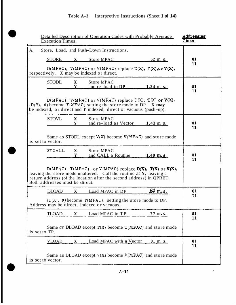
Table A-3. Interpretive Instructions (Sheet 1 of 14)
Detailed Description of Operation Codes with Probable Average Execution Times.
I A. Store, Load, and Push-Down Instructions.
STORE X Store MPAC .62 m. s .
D(MPAC), T(MPAC) or V(MPAC) replace D(X), T(X),or V(X), respectively. X may be indexed or direct.
STODL X Store MPAC Y and re-load in DP 1.24 m. s.
D(MPAC), T(MPAC) or V(MPAC) replace D(X), T(X) or V(X). (D(Y), 0) become T(MPAC) setting the store mode to DP. X may be indexed, o r direct and Y indexed, direct or vacuous (push-up).
STOVL X Store MPAC Y and re-load as Vector 1.43 m. s.
Same as STODL except V(X) become V(MPAC) and store mode is set to vector.
STCALL X Store MPAC Y and CALL a Routine 1.40 m. 8.
D(MPAC), T(MPAC), o r V(MPAC) replace D(X), T(X) o r V(X), leaving the store mode unaltered. Call the routine at Y, leaving a return address (of the location after the second address) in QPRET, Both addresses must be direct.
DLOAD X Load MPAC in D P .64 m. s .
I (D(X), 0 ) become T(MPAC), setting the store mode to DP. Address may be direct, indexed o r vacuous.
TLOAD X Load MPAC in TP . 77 m. s.
Same as DLOAD except T(X) become T(MPAC) and store mode is set to TP.
VLOAD X Load MPAC with a Vector .91 m. s.
Same as DLOAD except V(X) become V(MPAC) and store mode is set to vector.

Table A-3. Interpretive Inatructione (Sheet 2 of 14)
t i -
,SLOAD X Load MPAC in Single Precision . 74 m . s .
Same as DLOAD except (S(X), 0,O) become T(MPAC). X nay not be vacuous.
PDDL X Push Down and load MPAC in DP . B l m. a.
D(MPAC), T(MPAC) or V(MPAC) are pushed down; (D(X), 0 ) )ecome (T(MPAC) with the store mode set to DP. X may be dlrect, ndexed, o r vacuous.
PDVL X Push Down and load MPAC with a vector 1.14 m. a.
Same as PDDL except V(X) become V(MPAC) and the store mode s set to vector.
PUSH Push Down .55 m. e.
D(MPAC), T(MPAC) or V(MPAC) are pushed down.
SETPD X Set Push-down Pointer - .58 m. 8.
Set the Push-down Pointer PUSHIDC to X, where X is in local erasable memory. X must be direct.
B. Scalar Arithmetic Operations - All addresses may be direct, indexed, or vacuous.
DAD X DP Add 66 m. a.
D(MPAC)'+ D(X) replace D(MPAC). Set OVFIND on Overflow, and leave the overflow-corrected result in MPAC.
DSU X DP Subtract 66 m. s.
D(MPAC) -D(X) replace D(MPAC). Set OVFIND on overflow, and overflow-correct the result.
BDSU X DP Subtract From .74 m. s.
D(X) - D(MPAC) replace D(MPAC). Set OVFIND on overflow, and overflow-correct the result.
' 01 11
01 11
01 11
01 11
01 11
01 11
01 11
A-20
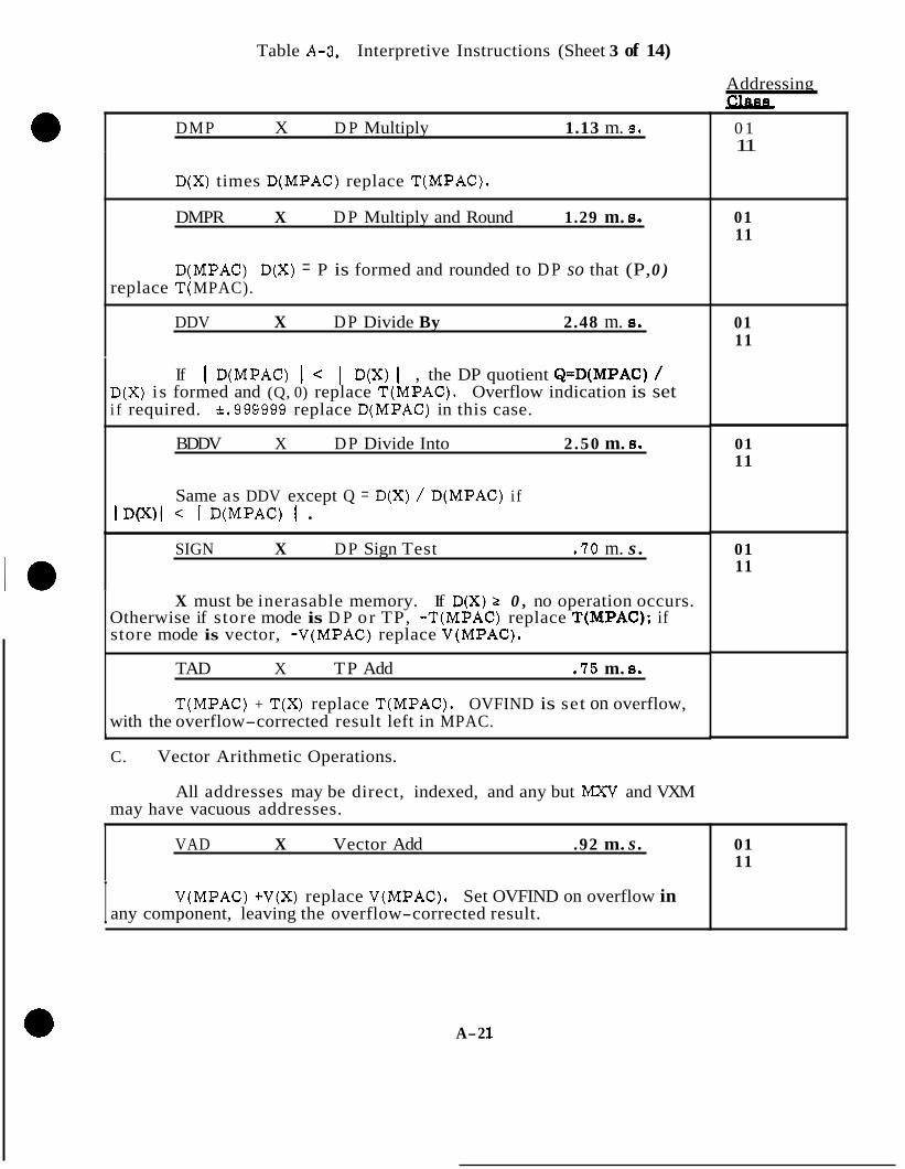
Table A-3, Interpretive Instructions (Sheet 3 of 14)
DMP X D P Multiply 1.13 m. 8.
D(X) times D(MPAC) replace T(MPAC).
DMPR X D P Multiply and Round 1.29 m. 8.
D(MPAC) D(X) = P is formed and rounded to D P so that (P, 0 ) replace T( MPAC).
DDV X DP Divide By 2.48 m. 8.
If I D(MPAC) I < I D(X) I , the DP quotient Q=D(MPAC) / D(X) is formed and (Q, 0) replace T(MPAC). Overflow indication is set i f required. ~ 9 9 9 9 9 9 replace D(MPAC) in this case.
BDDV X DP Divide Into 2 .50 m. 8.
Same as DDV except Q = D(X) / D(MPAC) if I D(X)I < I D(MPAC) I
SIGN X DP Sign Test .70 m. s .
X must be inerasable memory. If D(X) 2 0 , no operation occurs. Otherwise if store mode is D P or TP, -T(MPAC) replace T(MPAC); if store mode is vector, -V(MPAC) replace V(MPAC).
TAD X TP Add . 75 m. s .
T(MPAC) + T(X) replace T(MPAC). OVFIND is set on overflow, with the overflow-corrected result left in MPAC.
C. Vector Arithmetic Operations. L
All addresses may be direct, indexed, and any but MXV and VXM may have vacuous addresses.
Addressing Clasa
0 1 11
01 11
01 11
01 11
01 11
VAD X Vector Add .92 m. s .
I V(MPAC) +V(X) replace V(MPAC), Set OVFIND on overflow in any component, leaving the overflow-corrected result.
01 11
A-2 1

Table A-3. Interpretive Instructions (Sheet 4 of 14)
vsu X Vector Subtract .92 m. s.
V( MPAC) - V(X) replace V(MPAC). Set OVFIND on overflow in any component, leaving an overflow-corrected result.
BVSU X Vector Subtract From 1.17 m. s.
V(X) - V(MPAC) replace V(MPAC). Set OVFIND on overflow of any component, leaving an overflow-corrected result.
DOT X Vector Dot Product 3.08 m. s.
V(MPAC).V(X) replace T(MPAC), setting the store mode to DP. Set OVFIND if overflow occurs, leaving an overflow-corrected result.
vxsc X Vector Times Scalar 3.27 m.s.
If the initial store mode is Vector, each component of V(MPAC) is multiplied by D(X), the rounded products replacing their respective X components of V(MPAC). If the initial store mode is D P o r TP, change it to Vector, and each component of V(X) is multiplied by D(MPAC) to form V(MPAC) as above.
v/sc X Vector Divided by Scalar 5.39 m. 8.
If the initial store mode is Vector, each component of V(MPAC) is divided by D(X), the DP quotients replacing their respective com- ponents of V(MPAC). If the initial store mode is DP o r TP, it is changed to Vector, and each component of V(X) is divided by D(MPAC) to form V(MPAC). If overflow occurs in any component, the operation is terminated with OVFIND set and unspecified results in MPAC.
VXV X Vector Cross Product 4 .98 m. s.
V(MPAC) * V(X) replace V(MPAC). Set OVFIND if overflow occurs, leaving an overflow-corrected result.
VPROJ X Vector Projection 5.75 m. s.
D(MPAC).V(X~ V(X) replace V(MPAC), Set OVFIND on gverflow, and leave the result obtained with overflow-corrected Y(MPAC). V(Xg .
01 11
01 11
01 11
01 11
01 11
~~ "
01 11
01 11
A-22
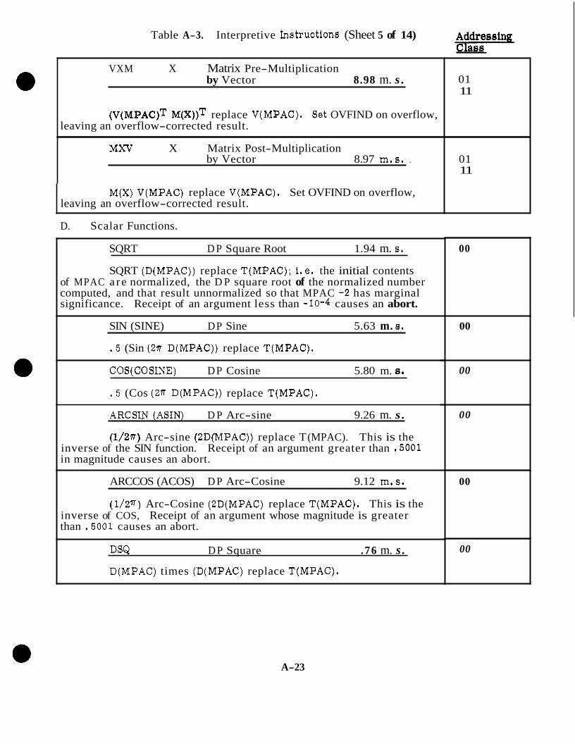
Table A-3. Interpretive Invtructions (Sheet 5 of 14) %E!@= VXM X Matrix Pre-Multiplication
by Vector 8.98 m. s . 01 11
(V(MPAC)T M(x))T replace V(MPAC). Set OVFIND on overflow,
MXV X Matrix Post-Multiplication
leaving an overflow-corrected result.
by Vector 8.97 m.8. . 01 11
M(X) V(MPAC) replace V(MPAC). Set OVFIND on overflow, leaving an overflow-corrected result.
D. Scalar Functions.
SQRT D P Square Root 1.94 m. 8.
SQRT (D(MPAC)) replace T(MPAC); i.e. the initial contents of MPAC a re normalized, the D P square root of the normalized number computed, and that result unnormalized so that MPAC +2 has marginal significance. Receipt of an argument less than -10-4 causes an abort.
SIN (SINE) DP Sine 5.63 m. 8,.
. 5 (Sin (27r D(MPAC)) replace T(MPAC).
COS(COS1NE) DP Cosine 5.80 m. a.
. 5 (Cos (ZT D(MPAC)) replace T(MPAC).
ARCSIN (ASIN) D P Arc-sine 9.26 m. s .
(1/2T) Arc-sine (2DWPAC)) replace T (MPAC). This is the inverse of the SIN function. Receipt of an argument greater than .5001 in magnitude causes an abort.
ARCCOS (ACOS) D P Arc-Cosine 9.12 m.s.
(1/W) Arc-Cosine (ZD(MPAC) replace T(MPAC). This is the inverse of COS, Receipt of an argument whose magnitude is greater than .5001 causes an abort.
DSQ D P Square . 76 m. s .
D(MPAC) times (D(MPAC) replace T(MPAC).
00
00
00
00
00
00
A-23
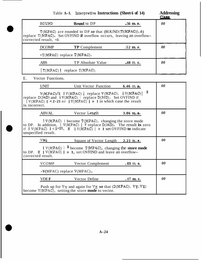
Table A-3. Ynterpretive Instructions (Sheet 6 of 14) Addressing
,ROUND , *Round to DP . 56 m. 8.
T(MPAC) a re rounded to DP so that (ROUND (T(MPAC)), 0 )
00
replace T(MPAC). Set OVFIND if overflow occurs, leaving an overflow- corrected result, + O .
DCOMP TP Complement .52 m. 8.
00 ABS T P Absolute Value . 48 m. s.
-T(MPAC) replace T(MPAC).
00
I T(MPAC) I replace T(MPAC).
E. Vector Functions.
UNIT Unit Vector Function 6.46 m. 8.
V(MPAC)/2 1 V(MPAC) I replace V(MPAC). I V(MPAC)
I V(MPAC) I < 2-21 o r I V(MPAC) I 2 1 in which case the result replace D(34D) and I V(MPAC) I replace D(36D). Set OVFIND if
is incorrect.
l 2
ABVAL Vector Length 3.86 m. 8.
1 V(MPAC) I become T(MPAC), changing the store mode to DP. In addition, I V(MPAC) I 2 replace D(34D). The result is zero if I V(MPAC) I ~ 2 - 2 1 . If I V(MPAC) I 2 1 set OVFIND to indicate unspecified result.
VSQ Square of Vector Length 2.21 rn. s.
I V(MPAC) I become T(MPAC), changing the store mode to DP. If I V(MPAC) I 2 1, set OVFIND and leave an overflow- corrected result.
VCOMP Vector Complement . 63 m. 8.
-V( MPAC) replace V( MPAC) . VDE F Vector Define .67 m. s.
Push up for V y and again for V z so that (D(MPAC), VY,VZ) become V(MPAC), setting the store mode to vector.
00
00
00
00
00
A-24

Table A-3. Interpretive Instructions (Sheet 7 of 14)
F. Shift Instructions. I
-
b T -
1 I
r
( -
P
1, Short Shifts
SR1 Scalar Shift Right . 85 m. a. SR2 , 85 m. s. SR3 .85 m. s. SR4 .85 m. 8.
T(MPAC) 2-j replace T(MPAC) (j= 1 , 2 , 3 , 4 ) .
s L1 Scalar Shift Left .72 m. 8.
s L2 .95 m. a. s L3 1.17 m. 8.
SL4 1.39 m. 8.
T ( M P A C ) ~ 2+j replace T(MPAC) (j = I, 2 , 3 , 4 ) . If significant . i t s are lost, set OVFIND but leave the overflow-corrected result as '(MPAC).
SRlR Scalar Shift Right . 99 m. 8.
SR2R and Round . 9 9 m. a. SR3R . 99 m. 8.
SR4R .99 m. s.
SL2R S L3R SL4R
and Round 1.10 m, 8.
1.32 m. 8. 1.54 m. a.
T(MPAC)x 2+j i s rounded to a DP number R and (R, 0 ) replace I'(MPAC) ( j = 1 , 2 , 3 , 4 ) . If overflow occurs, s e t OVFIND and leave the lverflow-corrected result as T(MPAC).
VSRl Vector Shift Right 2 .01 m. s. "
VSR2 TTCT
and Round 2 .01 m. 8. n A i - I
Each component of V(MPAC) is replaced by the original value multiplied by 2-j and rounded to DP. (j = 1(1)8).
;fa.;sing
00
00
00
A-25

Table A-3. Interpretive Instructions (Sheet 8 of 14)
VSLl VSL2 VSL3 VSL4 VSL5 VSL6 VSL7 VSL8
Vector Shift Left . 81 m. 8. 1.18 m. s. 1.55 m.8. 1.93 m. 8. 2.30 m. s. 2.68 m. 8. 3.05 m. 8. 3.43 m. 8.
Each component of V(MPAC) is replaced by the original k l u e multiplied by 2 +j ( j = 1(1)8). If overflow occurs in any component, leave the overflow-corrected result and set OVFTND.
2. General Shifts. Addresses may be direct o r indexed.
SR X General Scalar Shift 1.38 m. s. ~ ~ ~
Right +. 23 INTEGER (X/14),m. 8.
T(MPAC)x 2-' replace T(MPAC) where -42 < X <42 (X can )e negative only if the address was indexed. Address limits a re 0 < X < 42 .f direct and -128 < X s < 128 if indexed. X, is the stored address before .ndex modification: X is the net address in any case. On overflow leave ;he overflow-corrected result and set OVFIND.
SL X General Scalar Shift 1.03 m, s. Left +. 22 X m. s.
Same as SR except that T(MPAC)2 replace T(MPAC). X
SRR X General Scalar Shift 1.52 m.s. + Right and Round . 2 3 INTEGER (X/14) m. s.
Same as SR except that T(MPAC)x 2-x is rounded to a DP number 3 and (R, 0) replace T(MPAC). Address limits are 0 < X < 29 if direct.
S LR X General Scalar Shift 1.18 m. s. + Left and Round . 22 X m. s.
Same as SL except that T(MPAC)x 2 is rounded to a DP number X 3 and (R, 0) replace T(MPAC). Direct address limits are 0 < X < 14.
r Addressing
00
01 11
01 11
01 11
01 11
A-26
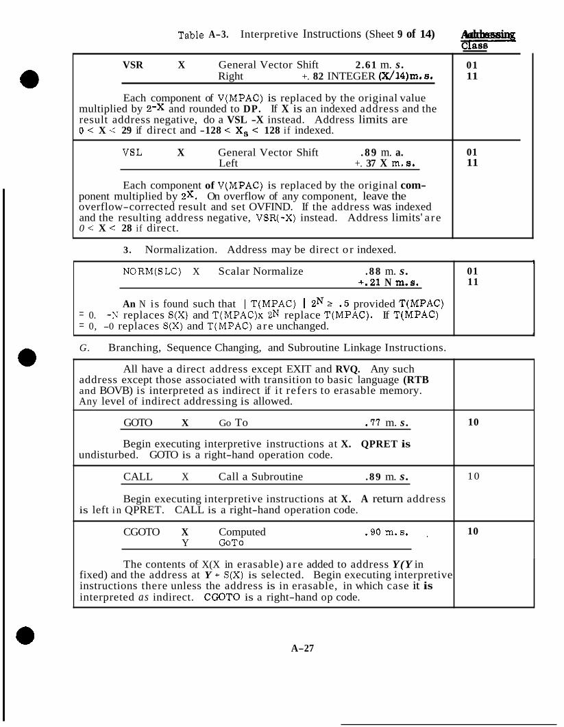
Table A-3. Interpretive Instructions (Sheet 9 of 14) Addressin 4 VSR X General Vector Shift 2.61 m. s .
11 Right +. 82 INTEGER (X/14)m. 8. 01
Each component of V(MPAC) is replaced by the original value multiplied by 2-x and rounded to DP. If X is an indexed address and the result address negative, do a VSL -X instead. Address limits are 0 < X -C 29 if direct and -128 < X, < 128 if indexed.
VSL X General Vector Shift . 8 9 m. a. 11 Left +. 37 X m. 8. 01
Each component of V(MPAC) is replaced by the original com- ponent multiplied by 2 x . On overflow of any component, leave the overflow-corrected result and set OVFIND. If the address was indexed and the resulting address negative, VSR(-X) instead. Address limits' a re 0 < X < 28 i f direct.
3. Normalization. Address may be direct o r indexed.
NORM(SLC) X Scalar Normalize . 88 m. s. 11 +.21 N m.8. 01
?
An N is found such that I T(MPAC) I 2N 2 . 5 provided T(MPAC) = 0. -N replaces S(X) and T(MPAC)x 2N replace T(MPAC). If T(MPAC) = 0, -0 replaces S(X) and T(MPAC) a re unchanged.
G. Branching, Sequence Changing, and Subroutine Linkage Instructions. A
All have a direct address except EXIT and RVQ. Any such address except those associated with transition to basic language (RTB and BOVB) is interpreted as indirect if i t refers to erasable memory. Any level of indirect addressing is allowed.
GOTO X Go To .77 m. s .
Begin executing interpretive instructions at X. QPRET is
10
undisturbed. GOTO is a right-hand operation code.
CALL X Call a Subroutine . 89 m. s.
Begin executing interpretive instructions at X. A return address
10
is left i n QPRET. CALL is a right-hand operation code.
CGOTO X Computed . 90 m.s. 10 Y GoTo
The contents of X(X in erasable) a re added to address Y(Y in fixed) and the address at Y + S(X) is selected. Begin executing interpretive instructions there unless the address is in erasable, in which case it is interpreted as indirect. C O T 0 is a right-hand op code.
A-27

Table A-3, Interpretive Instructions (Sheet 10 of 14) P CCALL X Computed 1.07 m. 8.
Same as CGOTO except that a return address is left in QPRET in addition. CCALL is a right-hand op code.
RVQUTCQ) Return Via QPRET .69 m. s .
Begin executing interpretive instructions at the location whose address is in QPRET. This may be used to return from a subroutine which contains no CALL or CCALL instructions. If QPRET contains the address of an erasable register, the address is interpreted as an in- direct address. RVQ is a "right-hand op code".
STQ(1TA) X Store QPRET .69 m. 8.
S(QPRET) replaces S(X) (X in erasable). This may be used to saw the return address in subroutines which contain CALL and CCALL instruc- tions. The STQ X in this case is eventually followed by GOTO X to return.
B PL X Branch Plugs .65 m. s. + .19 m. s . GO
If T(MPAC) 0, do a GOTO X. Otherwise, no operation occurs.
BZE X Branch Zero .65 m. s. +. 19 m. s. GO
If T(MPAC) = 0, do a GOTO X. Otherwise, no operation occurs.
BMN X Branch Minus .67 m. 8. +. 19 m. s . GO
If T(MPAC) 0, do a GOTO X. Otherwise, no operation occurs.
BHIZ X Branch High .6 m. 8. Order Zero +. 19 m. s. GO
If S(MPAC) = 0, do a GOTO X. Otherwise, no operation occurs.
BOV X Branch On .58 m. 8. Overflow +.23 m. s . GO
If OVFIND is set, reset it to zero and do a GOTO X. Otherwise, no operation occurs.
BOVB X Branch On .58 m. 6. Overflow to Basic +.16 m.6. GO
~~~~ ~~~~~ ~
If OV FIND is set, reset it to zero and begin executing basic instructions at X. Otherwise, no operation occurs, X must be in fixed memory.
A-2 8
10
10
1 0
10
10
10
10
10
10

Table A-3. Interpretive Instructions (sheet 11 of 14)
RTB X Return to Basic . 7 1 m. s.
Begin executing basic instructions at X. X must be in fixed memory.
EXIT Exit from Interpreter .26 m. s.
Begin executing basic instructions after the last op code o r Pddress word referenced by the interpreter as follows:
1) If EXIT is a left-hand op code, go to the word after the
2) If EXIT is a right-hand op code, go to the word following the EXIT instructions;
last address used by the left-hand op code.
EXIT is a right-hand op code.
H . Switch Instructions, b
SET X Set Switch 1.27 m. s.
Set switch X to 1. I I CLEAR X Clear Switch 1.25 m. s.
I Clear switch X to 0.
INVERT X Invert Switch 1.27 m. s.
Invert switch X; i. e. , i f 0 , set to 1; if 1, clear to 0.
SETGO X Set Switch 1.54 m. s. Y and Go To
Set switch X to 1 and do a GOTO Y, SETGO is a right-hand op code, I
CLRGO x Clear Switch Y and Go To
1.52 m. s.
Clear switch X to 0 and do a GOTO Y . CLRGO is a right-hand op code.
INVGO x Invert Switch 1.54 m. s. Y and Go To
I Invert switch X and do a GOTO Y. INVGO is a right-hand op code.
Addreesing Class -
10
10
10
10
10
10
10
10
A-29

1.
Table A-3. Interpretive Instructions (Sheet 12 of 14)
Switch Test Instructions.
BON X Branch i f ' 1.26 m. a. Y Switch On +. 23 m. 8.
If switch X is set to 1, do a GOTO Y . Otherwise, no operation occurs.
BOFF X Branch if 1.27 moa. . \ Y Switch Off + .23 m. a. GO
If switch X is cleared to 0, do a GOTO Y . Otherwise, no operation occurs.
BONSET X Branch if Switch 1.37 m.8. Y On, Setting Switch +.23 m. a. GO
Set switch X to 1. If initially set to 1, do a GOTO Y . Otherwise, no further operation occurs.
BOFSET X Branch if Switch 1.39 m. a. Y Off, Setting Switch +.23 m. a. GO
Set switch X to 1. If initially cleared to 0 , do a GOTO Y . Other- wise, no further operation occurs.
BONCLR X Branch if Switch 1.35 m.s. Y On, Clearing Switch +.23 m.8. GO
Clear switch X to 0 . If initially set to 1, do a GOTO Y . Other- wise, no further operation occurs.
, BOFCLR X Branch if Switch . 1.36 m. a. Y Off, Clearing Switch +.23 m. 8. GO
Clear switch X to 0 . If initially cleared to 0 , do a GOTO Y . Otherwise, no further operation occurs.
BONINV X Branch if Switch 1.37 m. s. Y On, Inverting Switch +. 23 m. a. GO .
Invert switch X. If originally set to 1, do a GOTO Y. Otherwise, no further operation occurs.
BOFINV X Branch if Switch 1.39 m.s. Y Off, Inverting Switch +. 23 m. a. CO
Invert switch X. If originally cleared to 0 , do a GOTO Y. Other- wise, no operation occurs.
10
10
10
10
10
10
10
10
A-3 0

Table A-3. Interpretive Instructions (Sheet 13 of 14)
J. Index Register Instructions.
AXT, 1 X Address to . 75 m. s. AXT, 2 X Index True
X replaces S(XT) (T = 1,2).
AXC, 1 X Address to . 7 6 m. s. AXC, 2 x Index Complemented
-X replaces S(XT).
LXA, 1 x Load Index . 78 m. s. LXA, 2 x from E rasable
S(X) replaces S(XT).
LXC, 1 x Load Index . 7 8 m. s . Lxc, 2 x from Erasable Complemented
-S(X) replaces S(XT).
SXA, 1 x Store Index . 78 m. 8. SXA, 2 x in Erasable
S(XT) replaces S(X).
XCHX, 1 X Exchange Index . 8 3 m. s. XCHX, 2 X with Erasable
S(XT) replaces S(X) which then replaces S(XT).
INCR, 1 X Increment Index . 7 6 m. s . INCR. 2 X
a
I The overflow-corrected sum of S(XT) and X replaces S(XT).
XAD, 1 X Index Register . 77 m. 6. XAD, 2 X Add
The overflow-corrected sum of S(XT) and S(X) replace S(XT).
xsu, 1 x Index Register Subtract 78 m. s, xsu, 2 x The overflow-corrected difference S(XT) - S(X) replaces S(XT).
10
10
10
10
10
10
10
10
10
A-3 3.
, . - . . . . . ..".. ". . . . . ^. . I_ - - .... . .

Table A-3. Interpretive Instructions (Sheet 14 of 14) Addressing - ?!lass s
a TIX, 1 X Transfer on Index .78 m. s . . TM, 2 X +.26 m. 8. GO
10
If S(XT) 5 S(ST) (T= I, 2) , no operation occurs. Otherwise, S(XT) - S(ST) replaces S(XT) and a GOT0 X is executed.
K. Miscellaneous Instructions. *
SSP X Set Single .67 m. s. 10 Y Precision
Y replaces S ( X ) . Y may be any constant: arithmetic, logical, address, etc.
STADR Push Up On .26 m. s. 00
I Store Code I During assembly, the appearance of STADR causes the next store
code to be stored complemented. During execution, STADR complements the next word to be referenced by the interpreter and enters the store code processor. STADR is a right-hand op code.
A-32
APPENDIX B.
EXPLANATION OF SAMPLE PROGRAM LISTING
INTRODUCTION
A page from a program listing is shown on Figure B-1. Call numbers 1 through 20 have been added for ease of explanation. The numbers below correspond with the call numbers on the figure.
1. Assembler language.
2. Program title,
3. Program listing page number.
4. Routine title.
5. Routine page number.
6. Basic data.
7. Calling sequence of the Alarm routine by another routine. Assume TC ALARM = L and OCT AAANN = L + 1. The alarm number is NN and the general area of the alarm i s AAA. A listing of the complete alarm numbers (AAANN) and their definitions is provided in the section of this study guide which contains the explanation of the Alarm routine.
8. This is a card used to indicate to the assembler to start the assembly of the routine at at octal address 5644.
9. This notifies the programmer that the EBANK being used is the same bank as is associated with FAILREG. In this case, E2 is used.
10. Column depicting the programmer's punch card number.
B- 1
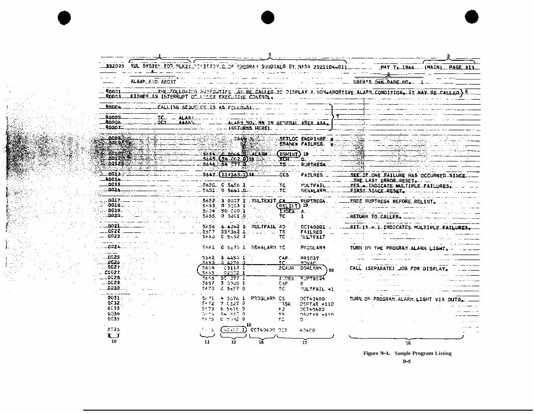
"" ..... . . . "-4- " -. "" . . . . . . . . . . " . . - " . . . . . . . - ... _" ... -E "
h .. " . . . . . . . . . . . -. . . . . . . . . . . . . . . . . . . . . . . . . . . . . . . . . . . . . . . . . . ..... . . . . . . . . . . . . . . . . . . . . . .. . . AL&PA.::D- A@ClT - . . . . . . - ..... -. ................... . . . ... - ".fLSJzE*S. an- "4 ". . . "
- - "- - "
...
cc35 . .
Of35
10 U
Figure B-1. Sample Program Listing
E 2

11. Column depicting the fixed memory address. FBANK 2 is implied when the general address is 40008 or 50008. FBANK 3 is implied when the general address is 60008 or 70008 . Any other FBANK is designated by, for example, 01, 2160 where 01 is F'BANK 1 and 2160 is the general address.
12. Column depicting the contents of the adjacent fixed memory address. The contents can be instruction o r data words. Two instruction words are explained in 13 and 14. A data word is explained in 15.
13. A typical instruction word is shown and is broken down into its parts below:
56 002 0 XCH Q (mneumonics)
Operation Code (noted as 05.6; an Exchange Instruction)
General Data Address (In this case Q )
Parity (In this case 0, because odd parity is used)
(TAKE CONTENTS OF Q AND PUT IT INTO A, AND TAKE THE CONTENTS OF A AND PUT IT INTO Q )
14. Shown below is a contraction of an instruction word as noted by the apostrophe mark.
11 ' 363 1 CCS FAILREG
To determine the operation code, general address, EBANK and Parity, the word will be converted from octal to binary:
BITS 15 14 13
BINARY NOTATION 0 0 1
OCTAL NOTATION 1
-
12 11 10
0 0 1
1
Bits 1 - 10 define the general address, 13638.
9 8 7
0 1 1
3
6 5 4
1 1 0
6
3 2 1
0 1 1
3 1
PARITY BIT
Bits 9 - 10 define the EBANK, 28.
Bits 11 - 15 define the operation code 01.08.
B-3
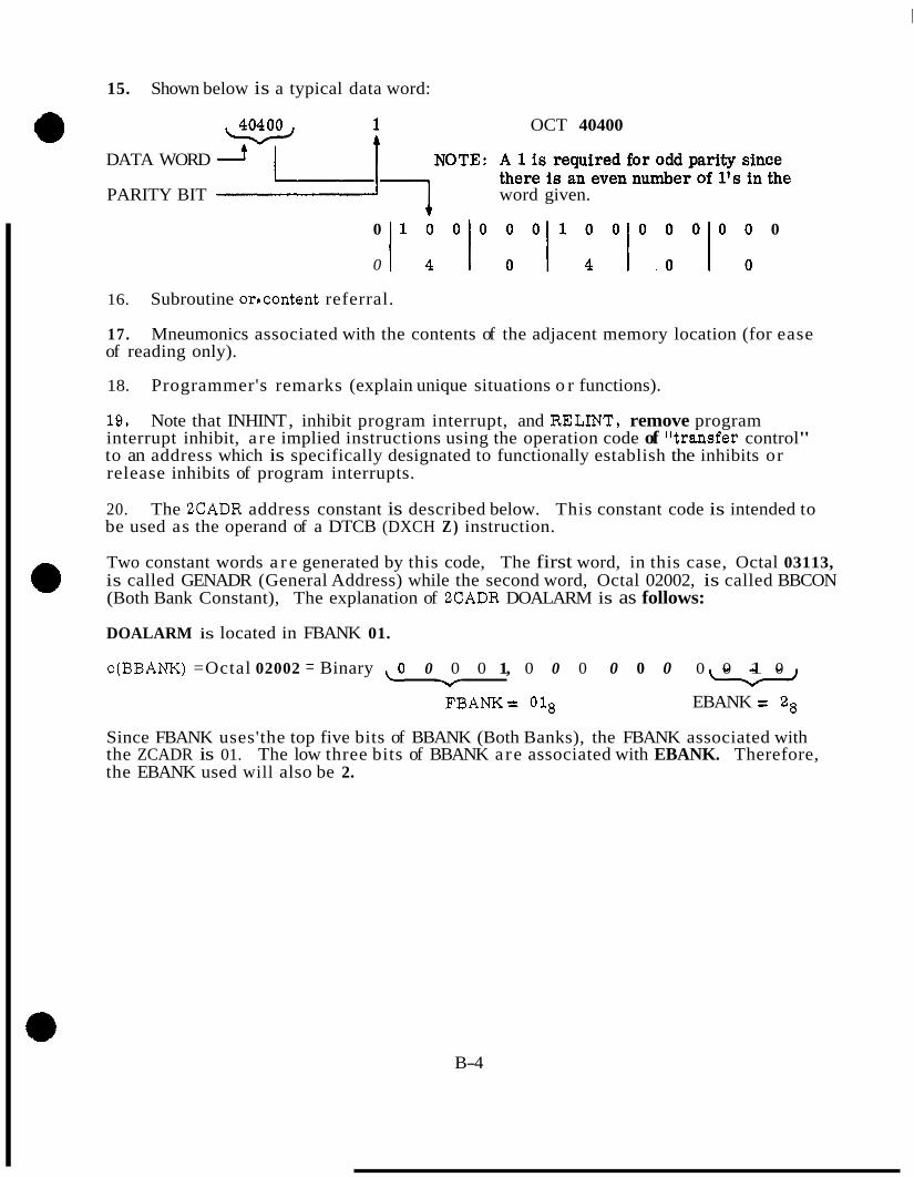
15. Shown below is a typical data word:
OCT 40400
DATA WORD
PARITY BIT word given.
0 1 0 0 0 0 0 1 0 0 0 0 0 0 0 0
0 / 4 1 0 1 4 1 . 0 1 0
16. Subroutine orrcontent referral.
17. Mneumonics associated with the contents of the adjacent memory location (for ease of reading only).
18. Programmer's remarks (explain unique situations o r functions).
19. Note that INHINT , inhibit program interrupt, and RELJNT, remove program interrupt inhibit, a re implied instructions using the operation code of Wansfer control" to an address which is specifically designated to functionally establish the inhibits or release inhibits of program interrupts.
20. The 2CADR address constant is described below. This constant code is intended to be used as the operand of a DTCB (DXCH Z ) instruction.
Two constant words a r e generated by this code, The first word, in this case, Octal 03113, is called GENADR (General Address) while the second word, Octal 02002, is called BBCON (Both Bank Constant), The explanation of 2CADR DOALARM is as follows:
DOALARM is located in FBANK 01.
c(BBANK) =Octal 02002 = Binary \ O 0 0 0 1, 0 0 0 0 0 0 0 0 1 0 I) U
FBANK = 018 EBANK = 28
Since FBANK uses'the top five bits of BBANK (Both Banks), the FBANK associated with the ZCADR is 01. The low three bits of BBANK are associated with EBANK. Therefore, the EBANK used will also be 2.
B-4
APPENDIX C
* INTERPRETNE PROGRAMMINC3
INTRODUCTION
The list-processing, algebraic interpreter is a Program Section in the CMCfs and LGC's Fixed Memory which is used to decode and execute mission Wction routines that a re stored in the computer's memory in interpretive language. Interpretive language is defined as a pseudo-algebraic language which is oriented toward the specific types of problems that must be solved on the Apollo Mission. Mission function routines can be prepared and then assembled in interpretive language wfih a considerable saving of required program-storage memory area, however the savings in program-storage is offset by the additional time required to perform a specific arithmetic operation,
The problem orientated programs are assembled by another computer program referred to as a YUL assembler. The assembled program is then wired into the fixed memory of the Apollo computer, The Interpreter Program Section converts the problem orientated program listing into the basic machine instructions, o r language, at the time on inhrpretive program is to be executed.
The organization and operation of the Interpreter Program Section and an analysis of interpretive language programming will be presented after a general discussion of multi- precision operation of the computers under program control.
C. 1 MULTI-PRECISION OPERATION
C. 1.1 MULTI-PRECISION NUMBERS. Most of the variables used in solving the cam- . plex, mathematical equations which make up the Apollo Guidance & Navigation Program require more accuracy in expression than can be obtained from 14 significant bits of binary data. Therefore, the interpretive language system for the Apollo computers is centered around multiple-precision computation. The Interpreter Program Section provides for three, multi-precision modes of operation:
a. Double Precision Mode: where the double-precision quantity x is stored at locations x and x + 1, and where the value of x is equated to [ c o + c(X+l) x 2-"].
h. Triple Precision Mode: where the triple-precision quantity u is stored at locations U, U+l, and U+2, and where the value of u is equated to c(U) + c(U +I) x 2-14 + C c(U +2) x , 2 4 7 . c. Double Precision Vector Mode: where the three, double-precision, orthogonal components r, s , and t of vector v are stored at locations V through V + 5, and where the value of the components are equated to r = [c(V) + c(V +1) x 2 - l q , s = [c(V+2) + c(V +3) x 2-14] , and t = [c(V+4) + c(V+5) x Z"4].
c-1

A s with single-precision variables in the basic machine language, the fixed, binary point for a multi-precision variable is considered to be located between bit positions 15 and 14 of the most significant 14 binary bits; and therefore, the variable is expressed entirely fractional.
C. 1.2 INTERPRETIVE ACCUMULATOR - MPAC. In order to carry out multi- precision calculations, the Interpreter Program Section is provided with a Multi-Purpose Accumulator (MPAC) which is used in a manner similar to the accumulator in the computer's Central Processor. The use of the MPAC is completely under program control. The MPAC consists of a set of seven E-Memory locations which are assigned by the Executive and which are, by definition, located in the Core Set Area for the active job that is currently being executed. Actually, the first seven locations in the Core Set Area for each job listed on the Job list can be considered to be the MPAC for that job, (See figure 2-1 Executive Core Set List), However, these locations are really used for temporary storage locations only if the job has been placed on the Job list, but not yet initiated; or, they are used to store the contents of the MPAC when the job is "put to sleep" or when the job is displaced for a higher-priority job by the Executive. The array of the seven locations of the MPAC is similar to the array for any multi- precision quantity (i. e. x, u, o r vi, except that in the Double-Precision Vector Mode, the three double-precision components are stored at 1ocationsFPAC + (MPAC + 1) x f I 4 ] , [(MPAC + 3) + (MPAC + 4) x 2-"] and[(MPAC + 5) + (MPAC + 6) x 2 -141 . , 1
and, location MPAC + 2 is not used,
C. 1 . 3 MEMORY ORGANIZATION, When a multi-precision quantity is stored in memory, the 14 significant bits stored at location K will always be the most signiflcant 14 bits of the quantity. The Interpreter Program Section automatically uses the locations which immediately follow location K (i. e. , K + 1, ---K + 5) as required to 0 store the lesser significant, 14 bit segments, A vector quantity will always have its orthogonal components stored in the order: i, j , k (i. e., i = K & K + 1, j = K + 2 & K + 3, k = K + 4 & K + 5). For this reason, whenever an E-Memory location is assigned to a particular, variable, multi-precision quantity, the next-higher-numbered location(s) must be reserved for storage of the quantity's lesser-significant, 14 bit segment@).
Most of the banks of the computer's Fixed-Switchable Memory and most of the E-Memory, including all of the E-Banks, may be used for interpretive language program sections, interpretive constants and variables. However, some limitations on usage and bank switching do exist, For interpretive considerations, Fixed-Switchable Memory can be divided into three parts, The lower part consists of Banks 04 through 17. Fixed- Fixed Memory (Banks 02 and 0 3 ) and Banks 00 and 0 1 Fixed-Switchable Memory contain the Interpreter Program Section itself, and are not available for interpretive language program sections or interpretive constants. The two upper (or higher) parts consist of the higher-order banks of Fixed-Switchable Memory (Banks 21 through 27) and the five, Fixed-Extension Channels (Banks 30 through 77) respectively. Bank 20 is not available for interpretive language program sections o r interpretive constants.
c-2

The Interpreter Program Section cannot switch Fixed-Extension Channels; it is assumed that any interpretive language program section can be contained in the first and second parts o r Fixed-Switchable Memory plus one Fixed-Extension Channel (eight banks). 0 Interpretive language program sections may be stored anywhere in the above three parts of Fixed-Switchable Memory that is available to interpretive language program sections, Any interpretive language program section that is located in the first or second part o r in any single channel of the third part of Fixed-Switchable Memory may branch to any other interpretive language program section that is not in another Fixed-Extension Channel. However, constants used by a program must be taken from the section con- taining the program.
Variables may be stored anywhere in erasable memory except the.input/output channels and registers (OO)8 through (57)s. The Interpreter Program Section cannot switch E-Banks; however, general-erasable memory from location ( 6 0 ) ~ through location (1377)s plus the current E-Bank (referred to as fllocal erasable") are together available for variable storage and temporary storage for calculated results. C. 1.4 THE PUSHLIST. The Interpreter Program Section provides a set of 38 locations in the Work Area assigned by the Executive that is known as the Pushlist. The name is derived from the term push-down list or a set of storage locations which exhibit a last-in, first-out behaviour (i. e., the last quantity entered into the list is normally the first quantity to be recalled.) Sufficient work-area locations are provided in the Pushlist to allow more than one double-precision, triple-precision, o r vector quantity to be stored. If three such quantities are stored before any quantity is recalled, the last quantity entered would be recalled first, the second quantity entered would be recalled next, and the first quantity entered would be recalled last. The push-down list that is provided by the AGC Interpreter Program Section is peculiar in its design in that any quantity stored anywhere in the list (double-precision, triple- precision, .or vector) may be read out by an indexed address operation without erasing 0 the quantity stored or changing its location with respect to any other quantity stored in the list. This peculiar capability is in addition to, and does not affect the normal capability which effectively "erases" the content of the last location used after recall to make it available for future temporary storage use.
The advantage of the Interpreter Program Section% peculiar type of push-down list is that a quantity may be formed -- for example, a double-precision multiply operation followed by a double-precision add operation -- and then stored in the Pushlist in the normal manner. %It may then be recalled as many times as is needed, without erasing it or changing its value o r location in the Pushlist as long as it is always recalled by the indexed-address method instead of the normal method. The indexed-address recall provision does not affect o r nullify the normal push-down capability (i. e., the last-in, first-out capability) of placing another quantity ?'on top of" the first quantity, and then recalling the last quantity first.
The manner in which quantities are entered into and recalled from the Pushlist will be discussed in the following section.
c- 3

C* 2 INTERPRETIVE INSTRUCTIONS
C. 2.1. ORGANIZATION O F INTERPRETIVE LANGUAGE PROGRAMMING. Interpretive language programming differs considerably in format from basic language programming. An interpretive instruction requires a 7-bit order code for expression; whereas, the basic language instruction order code requires only three to five bits. It is desirable to employ address codes for constants that allow these constants to appear in a different bank from the instruction program routine. It is also desirable to allow instruction program routines to branch to other routines anywhere in Fixed-Switchable Memory. Therefore, the interpretive address code must be a complete address code (a CADR); whereas, the basic language instruction address code gives only the sub- address within the current F-Bank.
Due to the limited CGC/LGC word length, it is not practical to pack the interpretive instruction order code and its relative address code into one word of computer memory. Interpretive instructions are packed in Interpretive Instruction Words (IIW's) with two order codes in bit positions 1 through 7 and 8 through 14, respectively. Addresses for constants and branch addresses are given a full computer memory word; whereas, the address of a variable in local erasable memory only requires 10 bits. Instructions which store the contents of an accumulator are generally the only ones whose addressing capability may be restricted to local erasable memory; therefore, these instructions contain an E-Memory address in bit positions 1 through 10, and the instruction order code in bit positions 11 through 14.
An IIW which contains two interpretive instruction order codes will normally be fol- lowed in an interpretive program listing with two Interpretive Address. Words (IAWfs) which contain the relative addresses for the two interpretive instructions. I€ the second interpretive instruction order code (bit positions 8 through 14) is a branch instruction, the second IAW below will be a branch address. Some interpretive instruc- tions such as function codes (for sine, cosine, square root, etc. functions) and some shift instructions (shift right one, shift left two, etc.) are unary in nature and require no IAW. (All function and shift instructions operate exclusively on an accumulator.)
When more than one mathematical execution is involved in solving an equation, the IIW's which program the executions, together with their relative IAW's, are formed into an Interpretive Program String. The first interpretive instruction order code in a program string will always be a LOAD Instruction to "load" the interpretive accumulator (MPAC). This instruction also sets the mode of operation (D. P . , T. p. or Vector Mode) of the Interpreter for the program string. When program control is transferred to the Interpreter, program operation extracts one IIW at a time from the Interpretive Program String, decodes the order code(s), then mates each interpretive instruction with its relative CADR. The CADR(s) is/are obtained from the IAW(s) immediately below the IIW in the program string. Each interpretive instruction is then executed by the Interpreter before another l IW is extracted from the program string. Interpretive Program Strings are normally terminated by a STORE Instruction which stores the resultant contents of the accumulator (MPAC) at some designated E-Memory storage location, The number of successive locations used to store the result is determined by the mode of operation for the program string.
c-4
c. 2 . 2 INTERPRETIVE INSTRUCTION ADDRESSING CLASSIFICATIONS. Two index registers, Xl , and X2, are provided in the Work Area that is assigned by the Executive
interpretive instruction order code specifies that a given IAW is to be indexed, the IAW will be stored complemented for Index Register 2, and stored normally if Index Register 1 is to be used. The indexed operand address is obtained by subtracting the content of the specified index register from the address specified in the IAW. In addition to the index registers, two step registers , S1 and 52, are provided for reducing the contents of the two index registers by specified "step-function1? amounts. A set of interpretive instruc- tion order codes is provided exclusively for manipulating the contents of the index registers and for counting and branching on the contents of the index registers by using the step registers.
The 7-bit order code which characterizes the interpretive instruction allows the general code set to be divided into four addressing classes. The 2 least-significant bits of the 7-bit code are used to specify the addressing class for the instruction:
1) fo r addressing modification of IAW's under Interpreter program control. When the
Class Code
00
01
11
10
Addressinp Class
Unary instructions which require no address (i. e., act only on an accumulator). Included in this class are the function order codes and some shift instructions.
Arithmetic instructions with non-indexed addresses. Address may be in any location of "local erasable" or any location of the part of Fixed-Switchable Memory from which the instruction was taken.
Arithmetic instructions with indexed addresses. Con- tent of an index register is subtracted from the given address to form the net operand address. Address lo- cation limitations of Class 01 apply. .
Branch instructions and index register instructions. This set of instructions is used to perform sequence changes and to modify the contents of an index register. Address may be any location of 1flocal erasable" o r any location in any part of locally available, Fixed-switchable Memory.
C. 2 . 3 CLASS 00 INSTRUCTIONS FUNCTION ORDER CODES AND UNARY SHIFT INSTRUCTIONS, The function order codes that are recognized by the interpreter pro- gram section include nine scales and five vector functions. A complete listing of these functions and other interpretive instructions appear in the appendix of this study guide. Each of these instructions operates on the contents of MPAC and therefore require no Interpretive Address Word in the interpretive string.
c-5
A total of thirty-two unary shift instructions are provided for the interpretive scaling adjustments that a re frequently required for fixed-point computation. These shift in- @ structions require no address because the individual order codes specify fixed, short- length shifts. The first 16, llshort-shifttt order codes provide: Scaler Shift Right, one to four places; Scaler Shift Left, one to four places; Scaler Shift Right And Round (to DP), one to four places; and, Scaler Shift Left And Round (to DP), one to four places. The remaining sixteen "short-shift!! order codes provide Vector Shift Right And Round (to DF), one to eight places; and, Vector Shift Left (without round), one to eight places.
C. 2 . 4 CLASSES 0 1 AND 11 INSTRUCTIONS, LOAD AND GENERAL SHIFT INSTRUCTIONS. These instructions form a special group of hterpretive instructions which operate only on the contents of MPAC. The instructions do, however, require either a direct address (class 01) o r an indexed address (class 11) to load the MPAC for an arithmetic o r shifting operation. Twelve store o r load instructions, seven general shift instructions, nine scaler arithmetic operations and ten vector arithmetic operations a re included in these classes of instructions.
C. 2 . 5 CLASS 10 INSTRUCTIONS, PROGRAM MECHANIZATION INSTRUCTIONS. The program mechanization instructions are used for branching, sequence changing, sub- routine linkage and for loading, storing and modifying the contents of the two index registers (Xl, X2). These instructions must be followed by an address word to indicate where to branch to etc. They do not affect the contents of MPAC. Forty instructions fall into this instruction class including fourteen used for sequence changing, branching and subrouting linkage under general interpretive language program control.
A second sub-group of fourteen instructions are used for setting, resetting, inverting, branching and testing a set of sixty-two valued indicators called Interpretive switches. These switches are located in four consecutive E-Memory locations called STATE,
tion requires an address word defining which switch is to be operated on. STATE +1, STATE +2, and STATE +3 with fifteen switches per location. Each instruc-
A third sub-group of class 10 instructions include 1010 instructions to manipulate the contents of the two index registers X1, and X2.
There are two additional program mechanization instructions with order codes that allow them to fa l l into the class 00. These instructions are STADR (recognize store code) and SSP (Set Single Precision).
A complete description of the interpretive instructions are included in the appendix.
C. 3 INTERPRETER PROGRAM OPERATION
C. 3 .1 NODAL ANALYSIS O F GENERALIZED PARENTHETICAL EXPRESSIONS. The format for the programmed solution of an equation which requires several Interpretive Program Strings and which uses the Pushlist can best be illustrated in the form of an
C-6

example. The equation to be programmed is the solution for the sum and difference roots of the familiar, second-order, quadratic equation:
a~ + b x + c = O 2
The equation for the roots is:
- b & x (root l), x (root 2) =
2a
a
An example of the interpretive programming techniques can beet be shown by a simplified flow-gram of the computer operations necessary to performed. Figure C-1 illustrates the symbols used in an Interpretive flowgram. Use of 8 temporary storage location, pushlist, is implied in this operation.
a+b ./b
Q a
t
Figure C-1. Network Mapping Symbols
c-7
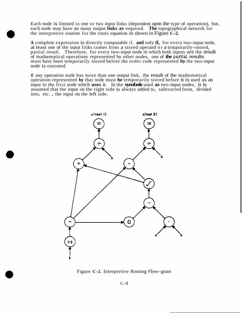
Each node is limited to one or two input links (dependent upon the type of operation), but, each node may have as many output links as required. The topographical network for the interpretive routine for the roots equation is shown in Figure C-2.
A complete expression is directly computable if, and only if, for every two-input node, at least one of the input links comes from a stored operand o r a temporarily-stored, partial result. Therefore, for every two-input node in which both inputs are the result of mathematical operations represented by other nodes, one of the partial results must have been temporarily stored before the order code represented by the two-input node is executed.
.e
If any operation node has more than one output link, the result of the mathematical operation represented by that node must be temporarily stored before it is used as an input to the first node which uses it. In the symbols used as two-input nodes, it is assumed that the input on the right side is always added to, subtracted from, divided into, etc. , the input on the left side.
Figure C-2. Interpretive Routing Flow-gram
C-8
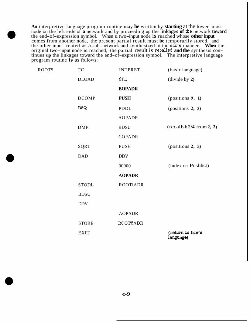
e An interpretive language program routine may be written by starting at the lower-most node on the left side of a network and by proceeding up the linkages of the network toward the end-of-expression symbol. When a two-input node is reached whose other input comes from another node, the present partial result must be temporarily stored, and the other input treated as a sub-network and synthesized in the same manner. When the original two-input node is reached, the partial result is recalled and the synthesis con- tinues up the linkages toward the end-of-expression symbol. The interpretive language program routine is as follows:
ROOTS TC INTPRET (basic language)
DLOAD SR1 (divide by 2)
BOPADR
DCOMP PUSH (positions 0 , 1)
DSQ PDDL (positions 2, 3)
AOPADR
DMP
SQRT
DAD
STODL
BDSU
DDV
STORE
EXIT
BDSU
COPADR
PUSH
DDV
00000
AOPADR
ROOTlADR
(recalls b 2/4 from 2, 3)
(positions 2, 3)
(index on Pushlist)
AOPADR
ROOTBADR
c-9

In the five Interpretive Program Strings which program the equation for the roots in double precision, the operand address for the operand (a) is assumed to be AOPADR; @ the location ROOTlADR is assumed to be the E-Memory storage location for the first root, X (root l), and the location ROOTBADR is used to store the second root, x (root 2). A special feature of the PUSH Instruction is that the pushed-down quantity is retained in the accumulator (MPAC) ; therefore, it can be temporarily stored for future use without disrupting the present computational flow. The STORE Instruction also retains the stored quantity in MPAC. The address word 00000 implicitly refers to the work-area assigned by the Executive; and, it is, by definition, Position Number 1 (DP) in the Pushlist. This is the indexed-address method of referring to the Pushlist that was described in paragraph 2.1.4. One additional feature of the PDDL and PDVL Instruc- tions is that they can be used to effectively exchange the contents of the accumulator (MPAC) with the last quantity previously entered into the Pushlist. If no operand address is provided for the load portion of these instructions, the Interpreter will extract the last quantity previously entered into the Pushlist, and then will temporarily store the present contents of MPAC in the location vacated by the quantity that was extracted for loading into MPAC. The STODL and STOVL Instructions will also extract the last quantity previously entered into the Pushlist if no operand address is provided for the load portion of the instructions.
C. 3 . 2 THE DISPATCHER ROUTINE - PROGRAM OPERATION. For the purpose of illustration, the Interpreter can be considered to be equivalent to a program-level, sequence generator. The Sequence Generator in the AGCfs Control Section consists of an SQ Decoder (command generator) and a Control Pulse Generator. The AGCIs Sequence Generator depends on the Central Processor to load an instruction order code from a programmed list of basic language instructions into the SQ Register (buffer), The Sequence Generator then decodes this order code and generates a sequence of control pulses which execute the instruction designated by the order code. The method by which
from the Sequence Generator in only two points: @ the Interpreter decodes and then executes the interpretive language instructions differs
a. The Interpreter is a program section in the AGC fs Fixed-Memory, and therefore, all interpretive decoding and execution is under basic language program control.
b, The Interpreter uses basic language program control to retrieve interpretive language order codes from memory, and therefore, it does not depend on any external source (such as the Central Processor in the analogy) to obtain each interpretive order code.
The Tnterpreter Program Section is made up of two major routines called the Dispatcher and the Executer. In the above analogy, the command generator (SQ Decoder) can be compared to the Dispatcher portion of the Interpreter. The Dispatcher Routine is made up of several minor routines and a number of subroutines. These routines decode the interpretive language order code(s) in each Interpretive Instruction Word 0, and also, decode the relative interpretive addresstes) and/or constant(s) in the relative Tnterpre- tive Address Word(s) (IAWfs). After taking care of the necessary internal f'housekeepingf' such as setting up the interpretive mode of operation, etc., the Dispatcher Routine stores the relative address in its decoded form in a location that is known to the Executer Routine. It then transfers Interpreter program control to the subroutine in the Executer that is commanded by the decoded, interpretive language order code.
c-10

e C. 3 . 2 . 1 THE INTERPRETIVE PROGRAM. The interpretive program section always uses the Interpretive Dispatcher to determine, is the word an instruction o r a store code word? what class of instruction code is it? and which of the many subroutines shall be selected? The Executer commands the specific subroutine called to be performed and returns operation to the Dispatcher. The Dispatcher operation requires entry by an instruction TC INTPRET each time an interpretive instruction string is begun.
C. 3 . 2 . 2 DISPATCHER FLOW. (see figure C-3. )
(1) Whenever the interpretive language on mode of the computer is selected the contents of register (Q) is stored in a temporary storage location LOC. Q contains the address of the instruction following TC INTPRET. The contents of FBANK is stored in BANKSET register enabling the program to return to the bank which requested INTPRET. Bit 15 of FBANK i s stored to indicate which half of fixed memory is accessable to the interpreter.
(2) The contents of the address defined in LOC is checked to determine if the contents are an instruction code pair o r an interpretive store code, For the later the operation is transferred to a store operation.
(3) If an instruction word is detected by the above test an edit operation is performed. The high seven bits of the instruction code is shifted into storage location EDOP. The low seven bits of the word is loaded into a location designated CYR. This transfer operation shifts bits 7 through 2 of the initial code to bits 6 through 1 of CYR and the original bit one of the O P code is shifted into bit 15 of CYR.
(4) Bit 15 of CYR is checked to determine if the content is a one o r zero. This is one step in determining the class of the interpretive instruction. A one in bit 15 defines a class 01 o r 11 instruction.
(5) Check the contents of bit 1 of CYR (this was originally bit 2 of the instruction OP code). If bit 1 = 1 a class 11 instruction an index operation is permitted in which the contents of the INDEX register is subtracted from the given address to form the net operand address. A TC to INDEX is commanded.
If bit 1 of CYR is 0' a class 0 1 address is defined. The address defines locations in any location in "local erasable" or any location in the half of Fixed-Switchable memory selected. A subroutine DIRADRES is selected eliminating the indexing operation.
(6) & (7) If bit 15 of CYR is a ' 0' when checked in (4) above, the contents of CYR are checked again to see if the code is all zeros o r a positive quantity. If all zeros an automatic exit is commanded. If a positive quantity is detected in CYR a TC to OPJUMP3 is commanded. Class 00 and 1 0 addresses are defined when bit 15 is ' 0' and the contents of CYR is positive.
(8) We have identified an arithmetic operation with a non-indexed address location - class 0 1 address - to this point. Now clear and subtract the contents of the address location LOC + 1 and see if bit 15 is a '1' or '0'. If the complemented contents
c-11

SAVE C(Q) IN LOC STORE FBANK AND
ADD 1 TO LOC BIT 15 TO UPDATE
1 1
I I CHECK CONTENTS O F ADDRESS IN LOC IS CONTENT AN IIW OR I AN ADDRESS CODE
(2) I I PERFORM EDIT OP- I
ERATION ON HIGH 7 BITS O F CONTENTS O F ADDRESS IN LOC. LOAD LOW 7 BITS O F CONTENTS O F ADDRESS IN LOC INTO CYR
(3
c j DOSTORE
TC AUTOMATIC
Figure C-3. Interpretive Program Flow (Sheet 1 of 14) c-12
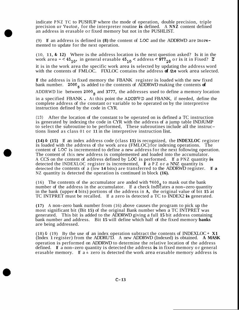
indicate P N Z TC to PUSHUP where the mode of operation, double precision, triple precision or.Vector, for the interpreter routine is defined. A N N Z content defined an address in erasable o r fixed memory but not in the PUSHLIST.
(9) If an address is defined in (8) the content of LOC and the ADDRWD are incre- mented to update for the next operation.
(10, 11, & 12) Where is the address location is the next question asked? Is it in the work area - < 4510, in general erasable 4510 < address < 9W10 o r is it in Fixed? I€ it is in the work area the specific work area is selected by updating the address word with the contents of FMLOC. FIXLOC contains the address of .the work area selected.
If the address is in fixed memory the FBANK register is loaded with the new fixed bank number. 20008 is added to the contents of ADDRWD making the contents of ADDRWD lie between 20008 and 3777, the addresses used to define a memory location in a specified FBANK . A t this point the ADDRWD and FBANK, if needed, define the complete address of the constant o r variable to be operated on by the interpretive instruction defined by the code in CYR.
(13) After the location of the constant to be operated on is defined a TC instruction is generated by indexing the code in CYR with the address of a jump table INDJUMP to select the subroutine to be performed, These subroutines include all the instruc- tions listed a s class 01 o r 11 in the interpretive instruction list.
(14) & (15) If an index address code (class 11) is recognized, the INDEXLOC register is loaded with the address of the work area (FMLOC) for indexing operations. The content of LOC is incremented to define a new address for the next following operation. The content of this new address is complemented and loaded into the accumulator. A CCS on the content of address defined by LOC is performed. If a PNZ quantity is detected the INDEXLOC register is incremented, If a P Z o r a NNZ quantity is detected the contents of a (low 14 bits) are transferred to the ADDRWD register. If a NZ quantity is detected the operation is continued in block (16).
(16) The contents of the accumulator are anded with 76008 to mask out the bank number of the address in the accumulator. If a check indicates a non-zero quantity in the bank (upper 4 bits) portions of the address in A, the original value of bit 15 at TC INTPRET must be recalled. If a zero is detected a TC to INDEX2 is generated.
(17) A non-zero bank number from (16) above causes the program to pick up the most significant bit (Bit 15) of the original Bank number when a TC INTPRET was generated. This bit is added to the ADDRWD giving a full 15 bit address containing bank number and address. Bit 15 will define which half of the fixed memory banks are being addressed.
(18) & (19) By the use of an index operation subtract the contents of INDEXLOC + X1 (Index 1 register) from the ADDRU’D. A new ADDRWD (Indexed) is obtained. A MASK operation is performed on ADDRWD to determine the relative location of the address defined. If a non-zero quantity is detected the address is in fixed memory o r general erasable memory. If a f zero is detected the work area erasable memory address is
C- 13

GI UPDATE ADDRWD
V DIRADRES,
CCS ON THE COMPLI- MENT OF THE CONTENTS O F ADDRESS DEFINED BY LOC+l
NNZ
UPDATE LOC UPDATE ADDRWD
( 9) , *
WHERE IS ADDRESS? IN FTXED
I IN GENERAL ERASABLE r FIXEDADR
UPDATE FBANK UPDATE ADDRWD TO LOCATION BETWEEN 20008 & 37778
INDJUMP+l c 1
Figure C-3. Interpretive Program Flow (Sheet 2 of 14)
C- 14
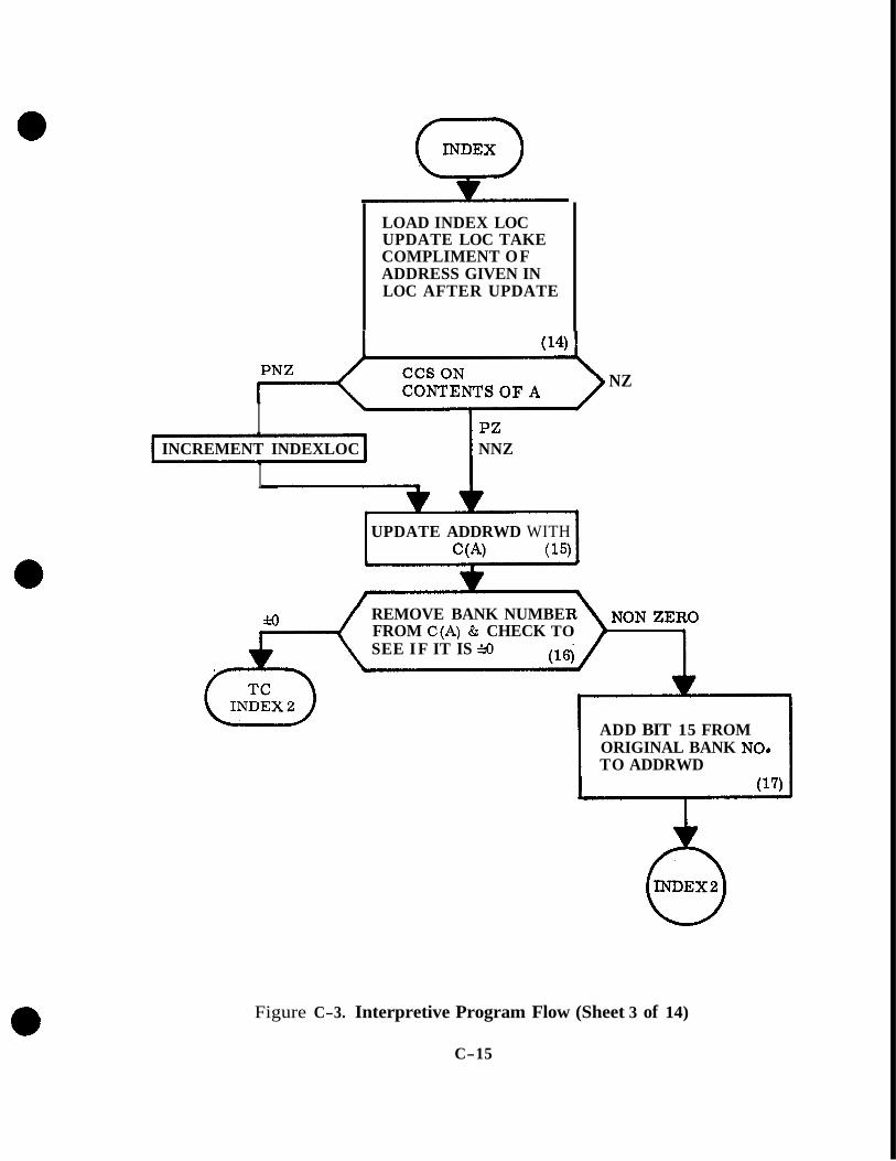
LOAD INDEX LOC UPDATE LOC TAKE COMPLIMENT OF ADDRESS GIVEN IN LOC AFTER UPDATE
NZ
I PZ INCREMENT INDEXLOC NNZ
I UPDATE ADDRWD WITH
c (A) (15)
REMOVE BANK NUMBE FROM C(A) & CHECK TO SEE I F IT IS rH)
ADD BIT 15 FROM
TO ADDRWD ORIGINAL BANK NO*
(17)
Figure C-3. Interpretive Program Flow (Sheet 3 of 14)
C-15

modified, as before, by adding the address of FMLOC (work area address) to ADDRWD to obtain the address of the specific work area to be used.
(20) & (22) If the check in block 18 indicated a NON Zero a further check is made on ADDRWD to determine if the address is in general erasable o r in fixed memory. E€ the address indicates a fixed memory location the high order bits of ADDRWD are loaded into FBANK and 20008 is added to ADDRWD and 017778 to make the contents of ADDRWD fall between 20008 and 37W8, the addresses associated with a fixed bank. A complete fixed memory location is now defined.
(21) & (23) If the address is in general erasable from above check, if in the work area (18, 19) and after defining a fixed memory location (20, 22) an index operation is performed. The contents of CYR - the applicable OP code is added to the address of INDJUMP to identify the subroutine for a specific interpretive instruction to be per- formed on the content of the address defined in blocks 18, 19, 20, and 22. Block 13 is again repeated as a TC operation.
(24) The operation which allowed a TC to OPJUMP 3 was a CCS on CYR. This operation would leave the absolute value of the contents decremented by 1 in the accumulator. This value is used to update the Fixed Bank register. The OPJUMP 3 subroutine is used whenever a class OO-Addressing code - (Unary instruction) is found in CYR.
(25, 26, & 28) Following the loading of FBANK register a CCS on CYR is again performed. If the path into OPJUMP 3 was from TC INTPRET CYR will contain a P N Z quantity however the possibility exists of entry into this subroutine from another point in the program. If a positive non-zero is found the contents of CYR is added to the address of UNAJUMP to select a subroutine falling into the UNARY instruction group (no address required perform operation on contents of MPAC, VAC, etc.). Several instructions included are: SQRT, SINE, UNIT.
If a positive zero (PZ) is found in CYR the previous CCS on CYR should have caused the program to exit. If a negative zero (NZ) is found a TC to SHORT T - short shift operation subroutine is generated.
(27) When a negative non-zero quantity is found in CYR a check is made on the MODE register. The MODE register defines the interpreter mode, double precision, triple precision or,vector. If a double or triple precision made is selected control is transferred to a short shift scalar operation subroutine SHORT T. If the vector mode is used to subroutine SHORT V - Vector Shift is selected.
(29) If the check on the contents of the address contained in LOC + 1 indicate that the content of the PUSHDOWN LIST (Block 8) is to be used as the operand for the arithmetic o r vector operation defined in CYR we end up in this routine (PUSHUP). The first operation in this routine is check the contents of CYR. If CYR contains a code 20 318, 22*, or 238 a normal usage of the contents of the PUSHDOWN list is signified. A TC to REGUP is generated. If, however, the contents of CYR are 0, 1, 2 , or 3 several possible variations in the use of PUSHLIST contents are possible. A further check on the contents of CYR is performed (Block 32).
8'
C-16

UPDATE ADDRWD & 10 BRANCH ZERO FIXED
1 ON ADDRWD AND 777008
(18)
UPDATE ADDRWD NO ADDRESS IN
(19)
h
INDEX CYR WITH INaTUMP
LOAD FBANK & MODIFY ADDRWD
(2 1) (22)
c
INDEX CYR WITH INDJUMP
(23)
I I TC TO
CODE IN C Y R
Figure C-3. Interpretive Program Flow (Sheet 4 of 14)
C- 17

0 OPJUMP3
I LOAD FBANK
I PNZ
NZ
PZ
PNZ b
Figure C-3. Interpretive Program Flow (Sheet 5 of 14)
C-18

(30) Depending on the MODE double precision, triple precision, o r vector which was determined elsewhere number of words in pushlist 2, 3, or 6 , to be used is entered into the accumulator.
(31) The accumulator contents, -2, -3, or -6 are added to PUSHLOC to define a specific address location. This same information is stored in ADDRWD to provide an address for the next operation.
(32, 33, 34, & 35) The contents of the accumulator, which will be a 7 , 6 , 5 , or 4 following the previous CCS (Block 29) are added to a constant negative 4. A check (CCS) is then made on the contents of the accumulator. The contents of the accumu- lator after the addition will be negative zero (4), positive zero (S), positive one (6), or positive two (7). Three possible types of operations are possible at this time:
a. An arithmetic operation which requires a standard type of operand regardless of the previous operation (standard operand). If this type of operation is defined a clear and subtract 2 (NOWORDS) is commanded for a double precision operation.
b. The second type of operation possible using the PUSHLIST is an operation in which the accumulator is loaded with a load code which is independent of the previous operation. Examples of these codes are VLOAD, DLOAD, TLOAD, PDDL, and PDVL. If this type of operation is selected by the OP code in CYR the accumulator, which contains a plus 1 or plus 2 is indexed with NOWORDS to select the double, triple o r vector mode of operation.
c. The third type of operation using the PUSHLIST as an address location for an operand is a reversing operation. If the last operation yielded a vector result the next operand should be a scaler. VXSC is an example of the operation requiring a reversal of this type. If this type of operation is commanded the contents of the MODE (0, -f 1) register are indexed with REVCNT to select the reversed conditions from the previous operation.
In all cases after completion of the selection of double, triple, or vector operation for selecting data from the PUSHLIST a TC to REGUP + 2 2 is commanded returning the operation to block (30) above.
(3G) In the event a store code was detected in the operation in Block (2), the type of store operation must be selected. The contents of the accumulator are transferred to storage as the ADDRESS WORD. The data in the accumulator is anded with a constant to pull out the local erasable memory locations, bits 1 through 10. The 10 bit address code is stored in the ADDRESS WORD and the complete address word (old one) is put back into the accumulator.
(37) If the store code was recognized the exact operation to be used in the storage routine must be defined. The high order bits, bits 11 through 14 of the contents of LOC + 1 are masked out, The resultant is multiplied by 0004008 to shift the contents of the accumulator from bits 11+14 to bits 1-5. This enables the programmer to use an index type operation to select a proper storage routine.
c-19

0 PUSHUP
CHECK ON THE TYPE O F OPERATION RE-
CLEAR & SUBTRACT THE NUMBER O F WORDS IN PUSHLIST TO BE USED IN AN OPERATION (30)
QUESTED BY CYR (2
CONTINUE CHECKS ON TYPE OF PUSHLIST 0 PE RATION OPERATION REQUESTED BY CYR
I
I INDEPENDENT O F LOST I
ADD THE NUMBER O F WORDS I N PUSHLIST TO BE USED TO PUSHLOC & SET ADDRWD = TO PUSH- LOC (3 1)
J
INDEX CYR WITH INDJUMP
(2 3)
TC TO INDJUMP +1 PLUS O P CODE
IN CYR
INDEX AC*CTJMULATOR WITH NO WORDS
Figure C-3. Interpretive Program Flow (Sheet 6 of 14)
c- 20

(38) The contents of the accumulator 00 to 3210 are indexed with a TC STOREJUMP to generate a store subroutine TC instruction which will in turn select one of the TC STORE commands in the STOREJUMP table.
(39) If the code is found in the high order bits of the old address word it is recog- nized as a command to update CYR with a CALLCODE. The CALLCODE register will contain a new OP code to be used in CYR in following operations.
(40, 41, 42, & 43) If the TC STOREJUMP transfers control to STORE 1 the address contained in ADDRWD is first updated with the contents of FlXLOC which contains the address of the work area selected. Block 41 identifies a work area address o r a general erasable address for storage. If a work area is defined FIXLOC is again used to update the ADDRWD. If a general erasable address is found in ADDRWD a storage operation is performed (Block 43). The storage operation will transfer the data contained in MPAC and MPAC + 1 into the erasable memory locations defined by ADDRWD and ADDRWD + 1. A double precision transfer to storage is thus performed using ADDRWD to define the location used for storage.
(44) After the initial transfer to storage of the double precision quantities a check is made to see if the quantity to be stored is a double o r triple precision quantity o r a vector quantity by looking at a MODE indicator. The MODE indicator will contain a zero for double precision, a plus one for triple precision o r a minus one for vector operations.
(45) If a plus one was found in MODE the third component of the triple precision quantity, which is located in MPAC + 2 is transferred to the erasable location defined in ADDRWD + 2. Operation is picked up in the DODLOAD subroutine. Triple pre- cision data is stored at this time.
(46) If the Vector mode of operation is detected the other two double precision components of the vector, the Y & Z components, must be stored. The 2nd and 3rd components of the vector are taken from MPAC + 3, 4 , and MPAC + 5, 6 . The contents of these four locations are transferred to the storage locations defined by ADDRWD + 2 , 3 , 4 , 5. MPAC + 2 does not contain a usable quantity as it is not used during vector mode operations.
(47) I€ the MODE indicator contained an indication of double precision o r the vector quantity is stored, a transfer control to Q is commanded. The contents of Q are the TC instruction of the next following address which commanded the STORE subroutine to be selected. The operations commanded are shown in the illustration.
(48) & (49) If a TC DODLOAD, or DOVLOAD the contents of CYR is updated with a new OP code to command a double precision o r vector load operation followed to a TC to DIRADRES. This indicates that a class 0 1 instruction address is to follow.
(50, 51, & 52) If a TC to DOVLOAD* or DODLOAD* is commanded (47 above) CYR is again updated with an OP code which will ca11 an address class 11 which indicates that an indexing register operation is permitted for an arithmetic operation.
c-2 1
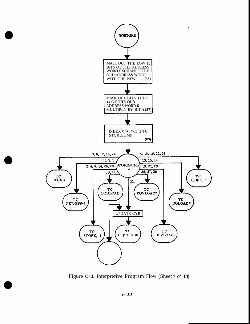
0 DOSTORE
MASK OUT THE LOW 10 BITS OF THE ADDRESS WORD EXCHANGE THE OLD ADDRESS WORD WITH THE NEW (36)
MASK OUT BITS 11 TO 14 O F THE OLD ADDRESS WORD & MULTIPLY BY BIT 6 (37)
1
INDEX C(A) WITH T C STOREJUMP
(38)
4,10,16,22,28
UPDATE CYR
Figure C-3. Interpretive Program Flow (Sheet 7 of 14)
c-22

UPDATE ADDRWD WITH FIXLOC
(40)
IS DATA TO BE
UPDATE ADDRWD
(42)
STARTS TO I
STORE CONTENTS O F MPAC, +1 IN LOCATION DEFINED BY ADDRWD, "1 (43)
Figure C-3. Interpretive Program Flow (Sheet 8 of 14)
C-23

-1 VECTOR OPERATION
+1 TRIPLE PRECISION WHAT MODE OF OPERATION?
OPERATION
PRECISION I 3 PERATION
Q VSTORE
I
1 VSTORE STORE 2nd i? 3rd COM- PONENT OF VECTOR
l
FROM MPAC, +3, +4, MPAC, +5, +6 IN LO- CATION DEFINED BY ADDRWD, +2, 3, 4, 5
(46)
LOAD C(MPAC+2) INTO LOCATION DEFINED BY ADDR-2 (45)
TRANSFER CONTROL 1 TO LOCATION DE- FINED IN THE Q REGISTER
6 DOVLOAD *
Figure C-3. Interpretive Program Flow (Sheet 9 of 14)
C-24
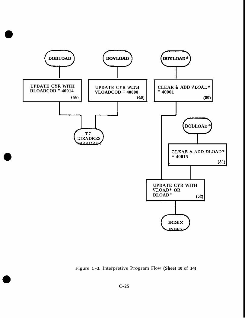
5) DODLOAD 7 DOVLOAD 9 DOVLOAD *
UPDATE CYR WITH DLOADCOD = 40014
(48)
I UPDATE CYR WITH VLOADCOD = 40000
(49) 4
0 DIRADRES
CLEAR & ADD VLOAD* = 40001
(50) J
c
I
I
DODLOAD *
I
CLEAR&ADDDLOAD* = 40015
_I (51)
UPDATE CYR WITH VLOAD* OR DLOAD * (52)
2 3 INDEX
Figure C-3. Interpretive Program Flow (Sheet 10 of 14)
C-2 5
(53, 54, 55, & 56) If a load instruction is found, as will generally be the case for a first interpretive instruction in a string, the single, double, triple precision o r vector load operation is defined. The contents of the ADDRWD plus the necessary following words, ADDRRD for single precision ADDRWD, + 1 for double precision; ADDRWD, + 1, 2 for triple precision and ADDRWD, + 1, 2 , 3 , 4 , 5 for vector operations are loaded into their appropriate location in MPAC. MPAC + 2 is not used for loading of vector quantities. In all cases the accumulator is loaded with an appropriate quantity to define interpretive MODE, 0 = double precision, + 1 = triple precision and -1 = vector. A TC to NEWMODE is commanded.
(57) Here' s where you come after you load MPAC for an operation and set up conditions describing the interpretive mode to follow. The MODE indicator is set to a minus 1, 0 o r plus 1 depending on what happened in Blocks 53, 54, 55, and 56.
(58) After the loading of the appropriate data into MPAC by the first instruction in an instruction string we have to look at the second instruction in the same IIW if there is one. The subroutine labeled DANZIG assures that the proper Fixed Banks are selected for future operations and looks at the contents of EDOP which should contain the second half of an IIU' if there was one. If an OP code was loaded in EDOP it would have been a Positive Non Zero o r a Positive Zero quantity. The CCS on a PZ quantity looks at NEWJOB to see if the job presently being done is the highest priority.
If a higher priority is detected a change job subroutine is called. If a higher priority job is not found we close the loop and go back to NEWOPS-1.
If on the check on EDOP an OP code is found we go to OPJUMP which will take the content of EDOP, decrement it by 1 and set this value into CYR and we go around again.
(59, 60, 61, & 62) For addressing class 10 instructions are located in CYR. The STOREJUMP + CYR transfer control instruction selects a subroutine for selecting a 15 bit address location. The address words are updated by the usual incrementing - method and the contents of CYR are summed with the address location MISCJUMP. The resulting command is to select a branching o r indexing routine to change the operation sequence of the computer program.
(63 ) & (64) The operations defined by the subroutine PDDL (Pushdown and Load MPAc) in Double Precision is the beginning of the EXECUTER portion of the inter- pretive program flow. In this operation the contents of the pushlist defined by the location in PUSHLOC, is transferred to MPAC, + 1. A check is made on MODE, is a double o r triple precision or the vector mode selected? Depending on the choice a subroutine for double, triple o r vector is chosen,
(65, 6 6 , & 67) If a triple precision (65) is detected in the check on MODE the third component of the data is taken from the pushlist and loaded into MPAC + 2. The MODE Switch is set to double precision. If a double precision (66) operation was detected MPAC + 2 is set to zero. If a vector operation (67) is found by looking at MODE, MPAC + 2 is set to zero and the remaining components of the vector are taken from the pushlist and loaded into MPAC + 3, 4, 5 , 6. The pushlist indicator, PUSHLOC, is decremented appropriately when data is removed from the list. The data removed from the list is no longer available from the list; it is destroyed. Upon completion of the transfer of data from the pushlist to MPAC for an operation to follow control is transferred back to DANZIG, the beginning of the interpretive
C-26
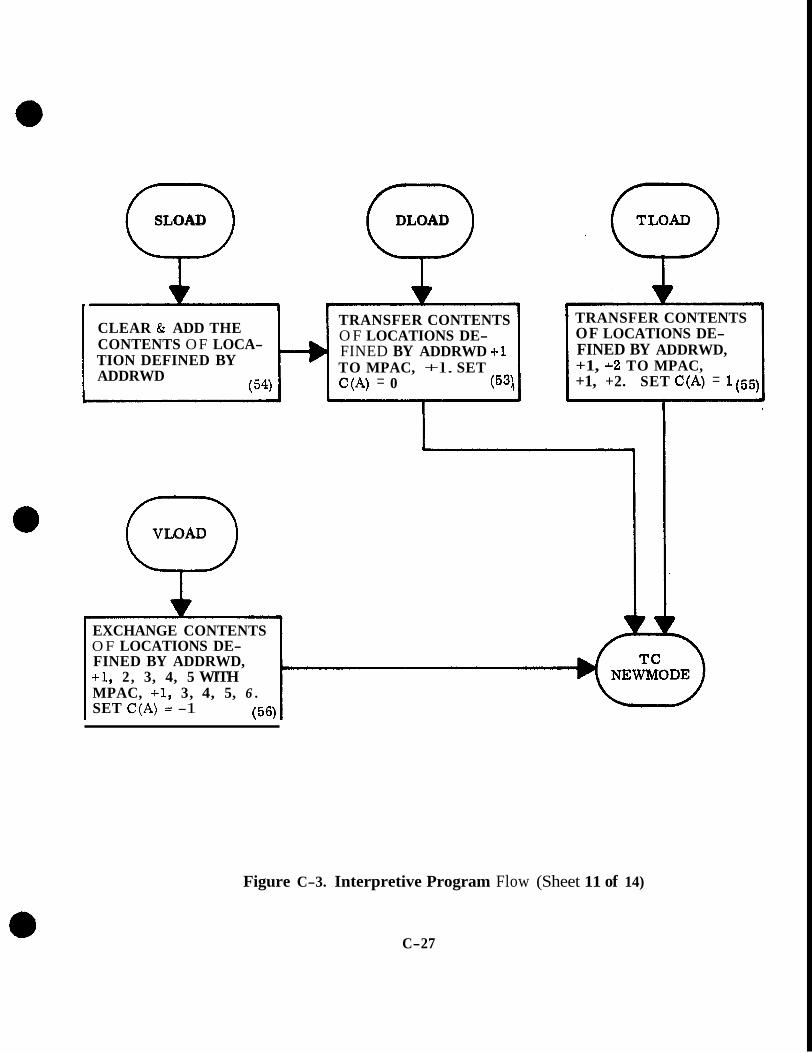
Q SLOAD Q DLOAD
++ CLEAR & ADD THE CONTENTS OF LOCA- TION DEFINED BY ADDRWD
( 54)
TRANSFER CONTENTS O F LOCATIONS DE- FINED BY ADDRWD +1 TO MPAC, +l. SET C(A) = 0 (531
Q VLOAD
TRANSFER CONTENTS OF LOCATIONS DE- FINED BY ADDRWD, +1, +2 TO MPAC, +1, +2. SET C(A) = 1(55)
EXCHANGE CONTENTS O F LOCATIONS DE- FINED BY ADDRWD, +l, 2, 3, 4, 5 WITH MPAC, +I, 3, 4, 5, 6 . SET C(A) = -1 ( 56)
Figure C-3. Interpretive Program Flow (Sheet 11 of 14)
C-27

n
0 NEWMODE
SET INTERPRETIVE MODE INDICATOR TO PROPER VALUE
DANZIG
DANZIG I PNZ CCS ON EDOP
PZ
CCS ON NEWJOB
. I pz
(-) NEWOPS-1
Figure C-3. Interpretive Program Flow (Sheet 12 of 14)
C-2 8

I J’ i
INCREMENT LOC & STORE CONTENTS O F ADDRESS DE- FINED (59)
i SELECT PROPER FBA GET O P CODE FROM
ICY” I
I > 1 1
BELWORK I N 1
UPDATE ADDRWD. TC TO GET O P CODE FROM MISCJUMP+ OP
MISCJUMP TABLE INST,
AXT AXC LXA I X C sxcl XCHX INCR T M XAD xsu BZE/GOTO BPL/BMN CALL/ITA RTB/BHIZ sw BOV(B)
CODE IN CYR
CYR OP CODE 00 0 1 02 03 04 05 06 07 10 11 12 13 14 15 16 17
Figure C-3. Interpretive Program Flow (Sheet 13 of 14) C-29

('9"") TRANSFER CONTENTS O F LOCATION DE- FINED BY ADDRWD, +1 INTO MPAC
L
DECREMENT PUSHLOC BY NUMBER OF WORDS FOR DOUBLE, TRIPLE OR VECTOR OPERA- TIONS
NNZ(-l) CCS ON MODE
(0 ) pz
ENDT PUSH ENDDPUSH ENDVPUSH
SET MODE = 0 LOAD SET MPAC +2 = 0 SET MPAC + 2 = 0 LOAD THIRD COMPONENT 2nd & 3rd COMPONENT O F TRIPLE PRECISION OF VECTOR INTO MPAC DATA INTO MPAC
I I
Figure C-3. Interpretive Program Flow (Sheet 14 of 14)
C-30

program routine to pick up the next OP code which i s stored in EDOP and we start over again. -
(2.4 SUMMARY
The interpretive section of the computer program i s used for programming convenience in the writing of problem orientated computer programs. This program motion consists of two basic parts a dispatcher and an executer. The dispatcher determines the type of inter- pretive program operation commanded by the operation code in an Interpretive Instruction Word and what type of addressing scheme i s to follow. The executer portion of the program is the specific subroutines which are selected by the dispatcher, which take an instruction such as SQUARE ROOT and perform a square root operation in the basic machine Ianguage. The executer subroutines always return the operation back to the dispatcher to select the next operation or to allow an exit from the interpretive program
The interpretive program by use of seven bit order codes and 15 bit address codes contribute a great deal to the versatility of the computer as a problem solving device.
C-31