pbn trainingfor operational ats … training study guide.pdf · this manual is the first step...
TRANSCRIPT

PBN TRAINING FOR OPERATIONAL ATS
PERSONNEL
SA PBN Implementation Project

ATNS/HO/C09/30/02/01 Page 2 of 184 14 July 2010
REVISION INDEX
Version Revision Date Reason for Change Pages
Affected
Draft 0.1 03/05/2010 New Document by Zach Froneman All
Draft 0.2 04/05/2010 Amended by Zach Froneman All
Draft 0.3 05/05/2010 Amended by Zach Froneman All
Draft 0.4 05/05/2010 Amended by Zach Froneman All
Draft 0.4.1 17/05/2010 Amended by Elsabé Wait &
Zach Froneman
All
Draft 0.4.2 21/05/2010 Amended by Zach Froneman All
Draft 0.4.3 21/05/2010 Amended by Zach Froneman All
Draft 0.4.4 21/05/2010 Amended by Elsabé Wait &
Zach Froneman
All
Draft 0.4.5 24/05/2010 Amended by Elsabé Wait &
Zach Froneman
All
Draft 0.5 25/05/2010 Amended by Elsabé Wait &
Zach Froneman
All
Draft 0.5.1 26/05/2010 Amended by Zach Froneman All
Draft 0.5.2 02/06/2010 Amended by Elsabé Wait,
Pamela Johnson & Zach Froneman
All
Draft 0.5.3 03/06/2010 Amended by Zach Froneman All
Draft 0.5.3 04/06/2010 Amended by Zach Froneman All
Draft 0.6 06/06/2010 Amended by Elsabé Wait,
Pamela Johnson & Zach Froneman
All
Draft 0.6.2 14/06/2010 Amended by Elsabé Wait,
Pamela Johnson & Zach Froneman
All
Draft 0.6.3 21/06/2010 Amended by Zach Froneman Sec. 4
Draft 0.6.4 28/06/2010 Amended by Zach Froneman Sec. 4 & 5
Draft 0.6.5 29/06/2010 Amended by Zach Froneman All
Draft 0.6.6 07/07/2010 Amended by Howard Hawk, Wayne
Lessard & Zach Froneman
All
Draft 0.6.6 14/07/2010 Amended by Zach Froneman,
formatting changes
All

ATNS/HO/C09/30/02/01 Page 3 of 184 14 July 2010
EXECUTIVE SUMMARY
The primary aim of this manual is to provide the operational ATS personnel with the required
theoretical knowledge to progress to the practical placation and use of PBN based RNAV procedures
in the daily provision of Air Traffic Services.
We will discuss the development from basic conventional navigation through to the possible
application of Performance-Based Navigation (PBN) as proposed by the International Civil Aviation
Organisation (ICAO). It also aims at providing the required reference material for the reader to
familiarise him or herself with the development, application and implications of widespread Area
Navigation (RNAV) application in a modern Air Traffic Management (ATM) System.
Recognising the current level of understanding of RNAV application, this manual will explain the flight
deck RNAV capabilities as well as the means to guarantee the navigation performance. This manual
will also explore the possible changes to the way in which ATM is provided at the moment as well as
to explain the expected benefits to the wider ATM community of increased use of the full RNAV
capabilities now available.
This manual is the first step towards the PBN training prescribed for operational Air Traffic Service
(ATS) by The ICAO. The second step will include simulation exercises that will demonstrate in a
practical manner the benefits of maximising RNAV applications.
The Body of the Document starts on Page 25
ATNS/HO/C09/30/02/01 Page 4 of 184 14 July 2010
REFERENCES
ICAO Manuals:
Doc 9613 Performance-Based Navigation Concept and Implementation Manual
Doc 9905 RNP AR Approach Design (Draft)
Doc 9849 GNSS Manual
Doc 9689 Manual on Airspace Methodology and Sep Minima
Doc 9573 Manual of Area Navigation (RNAV) Operation
Doc 9854 1ed ATM Operational Concept
Doc 9750 Global Air Navigation Plan
South African National Airspace Master Plan
ATNS ATM Roadmap.
SA PBN Implementation Roadmap
An Introduction to GNSS, Charles Jeffrey, P. Eng., NovAtel Inc, 2010.
Internet sites:
www.insidegnss.com – Engineering solutions from the GNSS community
www.spaceandtech.com – Andrews Space and Technology (AST)
www.en.wikipedia.org – Wikipedia, The Free Encyclopedia
www.igscb.jpl.nasa.gov – The International GNSS Service (IGS)
www.unoosa.org – United Nations Office for Outer Space Affairs, International Committee
on Global Navigation Satellite Systems
www.gps.gov – Global Positioning System, Serving the World
www.pnt.gov – Spaced-based Positioning Navigation & Timing
www.8051projects.info – 8051 Forum (Micro-controller projects)
www.faa.gov/air_ traffic
www.boeing.com/ commercial/aeromagazine/
www.directory.eoportal.org – Sharing Earth Observation Resources
www.gnssapplications.org – GNSS Applications and Methods
www.faa.gov – Federal Aviation Administration; GNSS Library

ATNS/HO/C09/30/02/01 Page 5 of 184 14 July 2010
TABLE OF CONTENT
REVISION INDEX ................................................................................................................................... 2
EXECUTIVE SUMMARY ........................................................................................................................ 3
REFERENCES ........................................................................................................................................ 4
TABLE OF CONTENT ............................................................................................................................ 5
ABBREVIATIONS .................................................................................................................................. 8
EXPLANATION OF TERMS ................................................................................................................. 12
1 AREA NAVIGATION (RNAV) SYSTEMS. ............................................................................... 25
1.1 Background .............................................................................................................................. 25
1.1.1 Conventional Navigation Methods and Procedures ................................................................. 26
1.1.2 RNAV Navigation Methods and Procedures ............................................................................ 29
1.1.3 WGS - 84 Geodetic Reference Datum ..................................................................................... 29
1.1.4 Historical Overview – Future Air Navigation System (FANS) .................................................. 30
1.2 Aircraft Area Navigation (RNAV) Computer System – Function .............................................. 32
1.2.1 Navigation ................................................................................................................................ 34
1.2.2 Navigation Database ................................................................................................................ 35
1.2.3 Flight Planning .......................................................................................................................... 37
1.2.4 Guidance and Control .............................................................................................................. 37
1.2.5 Display and System Control ..................................................................................................... 38
1.2.6 Manual Radio Position Updating .............................................................................................. 38
1.2.7 Automatic Radio Position Updating .......................................................................................... 38
1.3 Area Navigation (RNAV) Operations ........................................................................................ 39
1.3.1 RNAV Routes ........................................................................................................................... 39
1.3.2 RNAV Waypoint types .............................................................................................................. 40
1.4 Required Navigation Performance (RNP) – Specification ....................................................... 41
1.4.1 Functional Capabilities and Limitations .................................................................................... 41
1.4.2 RNAV System Requirements in terms of Accuracy, Integrity and continuity ........................... 43
1.5 RNAV and RNP Specific Functions ......................................................................................... 47
1.5.1 RNAV Leg types ....................................................................................................................... 47
1.5.2 Fixed Radius Paths .................................................................................................................. 49
1.5.3 Holding Pattern ......................................................................................................................... 51
1.5.4 Offset Flight Path ...................................................................................................................... 51
2 GLOBAL NAVIGATION SATELLITE SYSTEMS (GNSS) ...................................................... 52
2.1 Description of the GNSS Concept ............................................................................................ 52
2.1.1 Almanac.................................................................................................................................... 59
2.1.2 GNSS Segments ...................................................................................................................... 61
2.2 System Accuracy, Integrity, Continuity and Availability ........................................................... 64
2.2.1 Signal Performance Requirement ............................................................................................ 64
2.3 Augmentation ........................................................................................................................... 67
2.3.1 Ground-Based Augmentation System (GBAS) ........................................................................ 68
2.3.2 Aircraft-Based Augmentation System (ABAS) ......................................................................... 69
ATNS/HO/C09/30/02/01 Page 6 of 184 14 July 2010
2.3.3 Space-Based Augmentation System (SBAS) .......................................................................... 70
2.3.4 Ground-Based Regional Augmentation (GRAS) ...................................................................... 75
2.3.5 Techniques to improve GNSS receiver performance .............................................................. 75
2.3.6 GNSS Liability .......................................................................................................................... 79
2.4 Description of Receiver ............................................................................................................ 81
2.4.1 Display ...................................................................................................................................... 82
2.4.2 Functionality ............................................................................................................................. 85
2.4.3 Integrity Alerts .......................................................................................................................... 88
2.5 NAVSTAR GPS (Navigation Signal Timing and Ranging Global Positioning System)............ 90
2.6 GLONASS (Global Navigation Satellite System) ..................................................................... 93
2.7 GALILEO (The name given to the European Global Navigation Satellite System) ................. 95
2.8 Other Navigation Satellite Systems .......................................................................................... 97
2.8.1 China ........................................................................................................................................ 97
2.8.2 India .......................................................................................................................................... 99
2.8.3 Japan ...................................................................................................................................... 100
2.8.4 France .................................................................................................................................... 101
3 ALL WEATHER OPERATION ............................................................................................... 103
3.1 Conventional NAVAID Based Procedures ............................................................................. 104
3.1.1 Standard Instrument Departures (SIDs) and Standard Terminal Arrival Routes (STARs) .... 104
3.1.2 The Non-Precision Approach (NPA) ...................................................................................... 105
3.1.3 The Precision Approach (PA) ................................................................................................. 106
3.2 Continuous Descent Approach (CDA) ................................................................................... 108
3.3 Non-Conventional NAVAID Based Procedures (RNAV Approaches) ................................... 109
3.3.1 Overlay Procedures Concept ................................................................................................. 110
3.3.2 Standard Instrument Departures (SIDs) and Standard Terminal Arrival Routes (STARs) .... 111
3.3.3 Sensor Specific Area Navigation (RNAV) Procedures ........................................................... 115
3.3.4 RNP Procedures (Pre-PBN) ................................................................................................... 118
4 THE PERFORMANCE BASED NAVIGATION CONCEPT ................................................... 124
4.1 Description of Performance Based Navigation ...................................................................... 124
4.1.1 Introduction ............................................................................................................................. 124
4.1.2 Navigation Specification ......................................................................................................... 126
4.1.3 NAVAID Infrastructure ............................................................................................................ 132
4.1.4 Navigation Application ............................................................................................................ 132
4.1.5 Future Developments ............................................................................................................. 133
4.2 Airspace Concept ................................................................................................................... 141
4.2.1 Introduction ............................................................................................................................. 141
4.2.2 The Airspace Concept ............................................................................................................ 142
4.2.3 Airspace Concepts by Area of Operation ............................................................................... 143
4.3 Stakeholder Uses of Performance Based Navigation ............................................................ 146
4.3.1 Introduction ............................................................................................................................. 146
4.3.2 Airspace Planning .................................................................................................................. 147
4.3.3 Instrument Flight Procedure Design ....................................................................................... 148
4.3.4 Airworthiness and Operational Approval ................................................................................ 152
4.4 Implementation Guidance ...................................................................................................... 156

ATNS/HO/C09/30/02/01 Page 7 of 184 14 July 2010
4.4.1 Introduction to Implementation Process ................................................................................. 156
4.4.2 Process 1: Determine Requirements ..................................................................................... 157
4.4.3 Process 2: Identifying the ICAO Navigation Specification for Implementation ...................... 159
4.4.4 Process 3: Planning and Implementation ............................................................................... 161
4.4.5 Guidelines for Development of a New Navigation Specification ............................................ 166
5 CHANGES IN ATS DELIVERY DUE TO PBN IMPLEMENTATION..................................... 169
5.1 ATS Flight Plan Requirements ............................................................................................... 169
5.1.1 Conventional Navigation ........................................................................................................ 171
5.1.2 Non-Conventional Navigation ................................................................................................ 171
5.1.3 Designation of RNAV Routes ................................................................................................. 172
5.2 ATS Procedures ..................................................................................................................... 173
5.2.1 Control Procedures ................................................................................................................ 174
5.2.2 Contingency Procedures ........................................................................................................ 174
5.3 Separation Minima ................................................................................................................. 175
5.3.1 Longitudinal ............................................................................................................................ 175
5.3.2 Lateral..................................................................................................................................... 175
5.4 Mixed Equipage Environment ................................................................................................ 175
5.5 Transition Between Different Operation Environments .......................................................... 176
5.6 Phraseology ........................................................................................................................... 176
5.7 Reporting of Gross Navigational Errors ................................................................................. 176
5.8 RNAV STARs and SIDs ......................................................................................................... 177
5.8.1 Related Control Procedures ................................................................................................... 178
5.8.2 Radar Vectoring Techniques .................................................................................................. 178
5.8.3 Open and Closed STARs ....................................................................................................... 179
5.8.4 Altitude Constraints ................................................................................................................ 180
5.8.5 Descend/Climb Clearances .................................................................................................... 180
5.9 RNP Approach and Related Procedures ............................................................................... 181
5.10 Impact of Requesting a Change to Routing during a Procedure ........................................... 181
5.11 Fix/Waypoint Naming ............................................................................................................. 181
5.12 NAVAID Infrastructure Status Monitoring ............................................................................... 183
5.13 ATS System Monitoring .......................................................................................................... 183
ATNS/HO/C09/30/02/01 Page 8 of 184 14 July 2010
ABBREVIATIONS
ABAS Aircraft-based augmentation system
ACARS Aircraft Communications Addressing and Reporting System
ADS-B Automatic Dependent Surveillance — Broadcast
ADS-C Automated Dependent Surveillance — Contract
AFM Aircraft Flight Manual
AIP Aeronautical Information Publication
ANSP Air Navigation Service Provider
APV Approach Procedure with Vertical guidance
ATM Air Traffic Management
ATS Air Traffic Service(s)
Baro-VNAV Barometric Vertical NAVigation.
bps Bits per Second
C/A Code Coarse/Acquisition Code
CDGPS Canada-Wide Differential GPS
CDI Course Deviation Indicator
CDU Control and Display Unit
CFIT Controlled Flight Into Terrain
COSPAS Cosmitscheskaja Sistema Poiska Awarinitsch Sudow (Russian: space system for search of vessels in distress)
DGNSS Differential Global Navigation Satellite System
DPGS Differential Global Positioning System
DME Distance Measuring Equipment
DOP Dilution Of Precision
DR Dead Reckoning
DTED Digital Terrain Elevation Data
EASA European Aviation Safety Agency
ECAC European Civil Aviation Conference
ECEF Earth-Centred-Earth-Fixed
EGM 1996 Earth Gravitational Model (EGM96)
ESA European Space Agency
EUROCAE European Organisation for Civil Aviation Equipment
EUROCONTROL European Organisation for the Safety of Air Navigation
FAA Federal Aviation Administration
FAS Final Approach Segment
FDE Fault Detection and Exclusion
FDMA Frequency Division Multiple Access
FMS Flight Management System

ATNS/HO/C09/30/02/01 Page 9 of 184 14 July 2010
FOC Full Operational Capability
FTE Flight Technical Error
FRT Fixed Radius Transition
GAGAN GNSS Aided GEO Augmented Navigation (India)
GBAS Ground-Based Augmentation System
GEO GEOstationary orbit
GHz GigaHertz
GLONASS GLObal NAvigation Satellite System
GNSS Global Navigation Satellite System
GPS Global Positioning System
GRAS Ground-based Regional Augmentation System
GRS 1980 Geodetic Reference System (GRS80)
HEO Highly Elliptical Orbit
ICAO International Civil Aviation Organisation
IERS The International Earth Rotation and Reference Systems Service
INMARSAT International Maritime Satellite Organisation
INS Inertial Navigation System
IOV In-Orbit Validation
IRNSS Indian Regional Navigation Satellite System
IRS Inertial Reference System
IRU Inertial Reference Unit
JAA Joint Aviation Authorities
L1 The 1575.42 MHz GPS carrier frequency including C/A and P-code
L1C Future GPS L1 civilian frequency
L1F Future Galileo L1 civilian frequency
L2 The L2 civilian code transmitted at the L2 frequency (1227.6 MHz)
L5 The 1176.45 MHz 3rd
civil GPS frequency that tracks carrier at low signal-to-noise ratios
LAAS Local Area Augmentation System
LNAV Lateral NAVigation
Mb Megabit
MB Megabyte
MCDU Multifunction Control and Display Unit
MEL Minimum Equipment List
MHz MegaHertz
MNPS Minimum Navigation Performance Specification
ms millisecond
MSA Minimum Sector Altitude
MTSAT Multi-functional Transport SATellite
NAVAID NAVigation AId (also used as NAVAID)

ATNS/HO/C09/30/02/01 Page 10 of 184 14 July 2010
NAVSTAR NAVigation Satellite Timing and Ranging (synonymous with GPS)
NM Nautical Mile
NPA Non-Precision Approach
ns nanosecond
NSE Navigation System Error
PA Precision Approach
PBN Performance-Based Navigation
P-code Precision code
PDE Path Definition Error
PE-90 Parameters of the Earth 1990 (see PS90)
POH Pilot Operating Handbook
PPS Precise Positioning Service
PRN# Pseudo-Random Noise Number
PSR Primary Surveillance Radar
PS-90 Parametry Semli 1990 (see PE-90)
RAIM Receiver Autonomous Integrity Monitoring
RF Radius to fix
RNAV Area NAVigation
RNP Required Navigation Performance
RTK Real Time Kinematic
SAR Search And Rescue
SARSAT Search And Rescue Satellite Aided Tracking
SBAS Satellite-Based Augmentation System
SID Standard Instrument Departure
SSR Secondary Surveillance Radar
SNAS Satellite Navigation Augmentation System (China)
SOL Safety-Of-Life
SPS Standard Positioning Service
STAR STandard instrument ARrival
SV Space Vehicle
TLS Target Level of Safety
TSE Total System Error
UHF Ultra High Frequency
UTC Coordinated Universal Time
UTC(SU) Coordinated Universal Time (former Soviet Union, now Russia)
VDB VHF Data Broadcast
VHF Very High Frequency
VNAV Vertical NAVigation
VOR Very high frequency (VHF) Omnidirectional radio Range

ATNS/HO/C09/30/02/01 Page 11 of 184 14 July 2010
WAAS Wide Area Augmentation System
WGS World Geodetic System
WPT WayPoinT
QSSS Quasi-zenith Satellite System
ATNS/HO/C09/30/02/01 Page 12 of 184 14 July 2010
EXPLANATION OF TERMS
Absolute Accuracy. In GNSS positioning, absolute accuracy is the degree to which the position of
an object on a map conforms to its correct location on the Earth to an accepted coordinate system.
Acquisition. The process of locking onto a satellite‘s C/A code and P-code. A receiver acquires all
available satellites when it is first powered up, then acquires additional satellites as they become
available and continues tracking them until they become unavailable.
Aircraft-Based Augmentation System (ABAS). An augmentation system that augments and/or
integrates the information obtained from the other GNSS elements with navigation information
available on board the aircraft.
Note: — The most common form of ABAS is receiver autonomous integrity monitoring
(RAIM).
Aircraft Communications Addressing and Reporting System (ACARS). This is a digital data link
system for transmission of short, relatively simple messages between aircraft and ground stations via
radio or satellite. The protocol, which was designed by ARINC to replace their VHF voice service and
deployed in 1978, uses telex formats. SITA later augmented their worldwide ground data network by
adding radio stations to provide ACARS service. ACARS today operates in accordance with the
Aeronautical Telecommunications Network (ATN) protocol for Air Traffic Control communications and
by the Internet Protocol for airline communications.
Airspace concept. An airspace concept provides the outline and intended framework of operations
within an airspace. Airspace concepts are developed to satisfy explicit strategic objectives such as
improved safety, increased air traffic capacity and mitigation of environmental impact etc. Airspace
Concepts can include details of the practical organisation of the airspace and its users based on
particular CNS/ATM assumptions, e.g. ATS route structure, separation minima, route spacing and
obstacle clearance.
Air Navigation Service Provider (ANSP). An Air Navigation Service Provider is the organisation
that separates aircraft both on the ground and in flight in a dedicated block of airspace on behalf of a
state or a number of states. Air Navigation Service Providers are either government departments;
state owned companies, or privatised organisations.
Almanac. A set of orbit parameters that allows calculation of approximate GNSS satellite positions
and velocities. The almanac is used by a GNSS receiver to determine satellite visibility and as an aid
during acquisition of GNSS satellite signals.
Almanac data. A set of data which is downloaded from each satellite over the course of 12.5
minutes. It contains orbital parameter approximations for all satellites, GNSS to universal standard
time (UTC) conversion parameters, and single-frequency ionospheric model parameters.
Antipodal satellites. Antipodal satellites are satellites in the same orbit plane separated by 180° in
argument of latitude.
Anti-spoofing. Denial of the P-code by the control segment is called anti-spoofing. It is normally
replaced by encrypted Y-code.
ATNS/HO/C09/30/02/01 Page 13 of 184 14 July 2010
Approach Procedure with Vertical guidance (APV). An instrument procedure which utilises lateral
and vertical guidance but does not meet the requirements established for precision approach and
landing operations.
Area Navigation (RNAV). RNAV is a method of navigation that makes possible the operation of an
aircraft on any desired flight path within the coverage of station-referenced navigation aids or within
the limits of the capability of self-contained aids, or a combination of these.
Note: — RNAV systems are divided into two different types;
The first is the “older” more common standard system known simply as a RNAV
System.
The second and more modern type is known as a RNP system.
The fundamental difference between the two is that a RNP System is capable of on-board
navigation performance monitoring and alerting where as the “older” standard RNAV system
does not have these functions.
ATM Community. The aggregate of organisations, agencies or entities that may participate,
collaborate and cooperate in the planning, development, use, regulation, operation and maintenance
of the ATM system.
ATM System. A system that provides ATM through the collaborative integration of humans,
information, technology, facilities and services, supported by air and ground- and/or space-based
communications, navigation and surveillance.
ATS surveillance service. A term used to indicate a service provided directly by means of an ATS
surveillance system.
ATS surveillance system. A generic term meaning variously, ADS-B, PSR, SSR or any comparable
ground-based system that enables the identification of aircraft.
Note: — A comparable ground-based system is one that has been demonstrated, by
comparative assessment or other methodology, to have a level of safety and
performance equal to or better than monopulse SSR.
Baro-VNAV. A navigation system that presents to the pilot computed vertical guidance referenced to
a specified vertical path angle (VPA), nominally 3°. The computer-resolved vertical guidance is based
on barometric altitude and is specified as a VPA from reference datum height (RDH).
Base Station. A GNSS receiver that is employed as the stationary reference. It has a known position
and transmits messages for the rover receiver to use to calculate its position.
Broadcast Ephemerides. A set of parameters which describes the location of satellites with respect
to time, and which is transmitted (broadcast) from satellites.
Canada-Wide Differential Global Positioning System (CDGPS). The CDGPS is a free DGPS
service that is accessible coast-to-coast, throughout most of the continental United States, and into
the Arctic.

ATNS/HO/C09/30/02/01 Page 14 of 184 14 July 2010
Coarse Acquisition (C/A) code. A pseudo-random string of bits that is used primarily by commercial
GNSS receivers to determine the range to the transmitting GNSS satellite. The 1023 chip GPS C/A
code repeats every 1 mili-second giving a chip length of 300 m, which is very easy to lock onto.
Collaborative Decision Making (CDM). In the South African ATM context CDM will be understood
as meaning the following;
A process of collaboratively considering alternative understandings of a problem, an issue or a topic,
whilst recognising competing interests, priorities or constraints. Fundamental to this process is a
requirement to articulate in a concise and agreed upon manner the problem, issue or topic. This
process is aimed at improving the ATM system through increased information exchange among and
brings together the various parties in the ATM community. This process will result in an agreed to
application of the most appropriate action.
Control Segment. The master control station and the globally dispersed reference stations used to
manage the GNSS satellites, determine their precise orbital parameters, and synchronise their clocks.
Coordinated Universal Time (UTC). This time system uses the second-defined true angular rotation
of the Earth measured as if the Earth rotated about its Conventional Terrestrial Pole. However, UTC is
adjusted only in increments of one second. The time zone of UTC is that of Greenwich Mean Time
(GMT).
Dead Reckoning. The process of determining a vessel‘s approximate position by applying (DR) from
its last known position a vector or a series of consecutive vectors representing the run that has since
been made, using only the courses being steered, and the distance run as determined by log, engine
rpm, or calculations from speed measurements.
Differential GNSS (DGNSS). A technique to improve GNSS accuracy that uses pseudo-range errors
at a known location to improve the measurements made by other GNSS receivers within the same
general geographic area.
Dilution of Precision (DOP). A numerical value expressing the confidence factor of the position
solution based on current satellite geometry. The lower the value, the greater the confidence in the
solution. DOP can be expressed in the following forms:
GDOP: Uncertainty of all parameters (latitude, longitude, height, clock offset)
PDOP: Uncertainty of 3-D parameters (latitude, longitude, height)
HTDOP: Uncertainty of 2-D and time parameters (latitude, longitude, time)
HDOP: Uncertainty of 2-D parameters (latitude, longitude)
VDOP: Uncertainty of height parameter
TDOP: Uncertainty of clock offset time parameter
Doppler. The change in frequency of sound, light, or other wave caused by movement of its source
relative to the observer.
Theoretical Doppler: The expected Doppler frequency based on a satellite‘s motion relative
to the receiver. It is computed using the satellite‘s co-ordinates and velocity, and the
receiver‘s co-ordinates and velocity.
ATNS/HO/C09/30/02/01 Page 15 of 184 14 July 2010
Apparent Doppler: Same as Theoretical Doppler of satellite above, with clock drift correction
added.
Instantaneous Carrier: The Doppler frequency measured at the receiver, at the epoch.
Earth-Centred-Earth Fixed (ECEF). This is a co-ordinate system which has the X-axis in the Earth‘s
equatorial plane pointing to the Greenwich prime meridian, the S-axis pointing to the North Pole, and
the Y-axis in the equatorial plane 90° from the X-axis with an orientation which forms a right-handed
XYS system.
Ephemeris. A set of satellite orbit parameters that are used by a GNSS receiver to calculate precise
GNSS satellite positions and velocities. The ephemeris is used in the determination of the navigation
solution and is updated periodically by the satellite to maintain the accuracy of GNSS receivers.
Ephemeris data. The data down-linked by a GNSS satellite describing its own orbital position with
respect to time.
Epoch. Strictly a specific point in time. Typically when an observation is made.
Fault Detection and Exclusion (FDE). Fault detection and exclusion is a function performed by
some GNSS receivers. This function is designed to detect the presence of a faulty satellite signal and
to then exclude it from the position calculation.
Flight Management System (FMS). An integrated system consisting of an airborne sensor, receiver
and computer with both navigation and aircraft performance databases, which provides aircraft
performance and RNAV guidance to a display and automatic flight control system (autopilot).
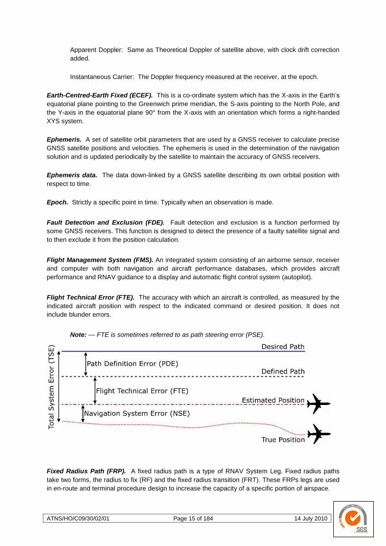
Flight Technical Error (FTE). The accuracy with which an aircraft is controlled, as measured by the
indicated aircraft position with respect to the indicated command or desired position. It does not
include blunder errors.
Note: — FTE is sometimes referred to as path steering error (PSE).
Fixed Radius Path (FRP). A fixed radius path is a type of RNAV System Leg. Fixed radius paths
take two forms, the radius to fix (RF) and the fixed radius transition (FRT). These FRPs legs are used
in en-route and terminal procedure design to increase the capacity of a specific portion of airspace.
ATNS/HO/C09/30/02/01 Page 16 of 184 14 July 2010
Fixed Radius Transition (FRT). The fixed radius transition leg may be employed when there is a
requirement for a curved path to be used during en-route procedure design. The FRT leg is defined
by radius, arc length and a fix.
RNP systems capable of ―flying‖ this leg type, are also capable of conforming to the same track-
keeping accuracy during the turn as in a straight line segments in accordance with the navigation
specification published for the portion of airspace within which this manoeuvre is required.
Bank angle limits for different aircraft types and winds aloft are taken into account in procedure
design. This turn has two possible radii, 22.5 NM for high altitude routes (above FL195) and 15
NM for low altitude routes. Using such path elements in a RNAV route enables improvement in
airspace usage through more efficient and reduced spacing between parallel routes.
Flexible Use of Airspace (FUA). Within the context of this document, FUA is understood to mean;
Airspace is no longer designated as purely "civil" or "military" airspace, but considered as one
continuum and allocated according to user requirements. This allocation will done by the ANSP and in
accordance with an agreed to CDM process. Any necessary airspace segregation is temporary and
based on real-time usage within a specific time period. Contiguous volumes of airspace are not
constrained by national boundaries.
Flight profile. The flight path of an aircraft expressed in terms of altitude, speed, range, time and
manoeuvre.
Galileo. Galileo will be the European Union‘s own global navigation satellite system, providing a
highly accurate, guaranteed global positioning service under civilian control. The fully deployed
Galileo system will consist of 30 satellites (27 operational + 3 active spares), positioned in three
circular orbits, 23 616 km above the Earth, and at an inclination of the orbital planes of 56° with
reference to the equatorial plane.
Gate to Gate. A concept where the air traffic operations of ATM community members are such that
the successive planning and operational phases of their processes are managed and can be
achieved in a seamless and coherent manner.
Geocentric. Relating to, measured from, or with respect to the centre of mass of the Earth.
Geodetic System. Geodetic systems or geodetic data are used in geodesy, navigation, surveying by
cartographers and satellite navigation systems to translate positions calculated in terms of X, Y and S
coordinate models into conventional latitude and longitude position.
Ground-Based Augmentation System (GBAS). A ground-based augmentation system is a system
that supports wide-area or regional augmentation through the use of additional satellite-broadcast
messages. Such systems are commonly composed of multiple ground stations, located at accurately-
surveyed points. The ground stations take measurements from one or more of the GNSS satellites,
the satellite signals, or other environmental factors which may impact the signal received by the
users. Using these measurements, information messages are created and sent to one or more
satellites for broadcast to the end users. Generally, GBAS networks are considered localised,
supporting receivers within 20km, and transmitting in the very high frequency (VHF) or ultra high
frequency (UHF) bands.

ATNS/HO/C09/30/02/01 Page 17 of 184 14 July 2010
Geo-stationary. A satellite orbit along the equator that results in a constant fixed position over a
particular reference point on the Earth‘s surface.
Global Navigation Satellite System (GLONASS). GLONASS is a radio satellite navigation system,
the Russian counterpart to the United States‘ GPS and European Union‘s Galileo positioning
systems. When complete, the GLONASS space segment will consist of 24 satellites in 3 orbital
planes, with eight satellites per plane. The satellites are placed into nominally circular orbits with
target inclinations of 64.8° and an orbital height of about 19 140 km, which is about 1 050 km lower
than GPS satellites.
Global Navigation Satellite Systems (GNSS). GNSS is the standard generic term for satellite
navigation systems (Sat Nav) that provide autonomous geo-spatial positioning with global coverage.
GNSS allows small electronic receivers to determine their location (longitude, latitude, and certain
receivers also altitude) to within a few meters using time signals transmitted along a line-of-sight by
radio from satellites. Receivers calculate the precise time as well as their position, which can be used
as a reference in navigation computers.
The Global Positioning System (GPS) is a space-based global navigation satellite system that
provides reliable location and time information in all weather and at all times and anywhere on or near
the Earth where there is an unobstructed line of sight to four or more GPS satellites. It is maintained
by the United States government and is freely accessible by anyone with a GPS receiver.
Ground-Based Regional Augmentation System (GRAS). Each of the terms, ground-based
augmentation system (GBAS) and ground-based regional augmentation system (GRAS) describe a
system that supports augmentation through the use of terrestrial radio messages. As with the satellite
based augmentation systems, ground-based augmentation systems are commonly composed of one
or more accurately surveyed ground stations, which take measurements concerning the GNSS, and
one or more radio transmitters, which transmit the information directly to the end user. GRAS is
applied to systems that support a larger (more than 20km), regional area, and transmit in the VHF
bands.
INMARSAT. INMARSAT plc. is a British satellite telecommunications company, offering global,
mobile services. It provides telephony and data services to users worldwide, via portable or mobile
terminals which communicate to ground stations through eleven geosynchronous telecommunications
satellites. Inmarsat's network provides communications services to a range of governments, aid
agencies, media outlets and businesses with a need to communicate in remote regions or where
there is no reliable terrestrial network.
An Inertial Navigation System (INS) is a navigation aid that uses a computer, motion sensors
(accelerometers) and rotation sensors (gyroscopes) to continuously calculate via dead reckoning the
position, orientation, and velocity (direction and speed of movement) of a moving object without the
need for external references. It is used on vehicles such as ships, aircraft, submarines, guided
missiles, and spacecraft. Other terms used to refer to inertial navigation systems or closely related
devices include inertial guidance system, inertial reference platform, inertial instrument, and many
other variations.

ATNS/HO/C09/30/02/01 Page 18 of 184 14 July 2010
Lateral Navigation (LNAV). LNAV refers to navigating over a ground track with guidance from an
electronic device which gives the pilot (or autopilot) error indications in the lateral plane only and not
in the vertical plane. In aviation lateral navigation is one of two guidance types: linear guidance and
angular guidance.
Linear guidance means that the actual position of the aircraft, i.e. the deviation left or right of the
desired ground track is available as a distance.
In angular guidance, the error indication is given in degrees of arc from the desired line relative to
a ground-based navigation device.
To provide an illustration, as the aircraft approaches the ground-based navigation device whilst
maintaining a constant angular error, the aircrafts distance from the desired ground line
decreases. In the context of aviation instrument approaches, an LNAV approach (one that uses
lateral navigation) is implied to be a approach using GNSS as the primary navigation source and
to have linear lateral guidance. A VOR based approach will have angular lateral guidance.
The FMS mode is normally called LNAV or Lateral Navigation for the lateral flight plan. LNAV
provides roll steering command to the autopilot and VNAV provides speed and pitch or altitude
targets.
L-band. L-band is a frequency range between 390 MHz and 1.55 GHz which is used for satellite
communications and for terrestrial communications between satellite equipment. L-band includes
GNSS carrier frequencies L1, L2, CDGPS and the Omni-STAR satellite broadcast signal.
Minimum Navigation Performance Specification (MNPS). A specified set of minimum navigation
performance standards which aircraft must meet in order to operate in MNPS designated airspace. In
addition, aircraft must be certified by their State of Registry for MNPS operation. The objective of
MNPS is to ensure the safe separation of aircraft and to derive maximum benefit, generally through
reduced separation standards, from the improvement in accuracy of navigation equipment developed
in the recent years.
Mixed navigation environment. An environment where different navigation specifications may be
applied within the same airspace (e.g. RNP 10 routes and RNP 4 routes in the same airspace) or
where operations using conventional navigation are allowed in the same airspace with RNAV or RNP
applications.
Multipath Errors. GNSS positioning errors caused by the intersection of the satellite signal and its
reflections.
Nanosecond. 1 x 10⁻⁹
second.
Navigation aid (NAVAID) infrastructure. NAVAID infrastructure refers to space-based and/or
ground-based navigation aids available to meet the requirements in the navigation specification.
Navigation application. The application of a navigation specification and the supporting NAVAID
infrastructure, to routes, procedures, and/or defined airspace volume, in accordance with the intended
airspace concept.
Note: — The navigation application is one element, along with communication, surveillance
and ATM procedures which meet the strategic objectives in a defined airspace
concept.

ATNS/HO/C09/30/02/01 Page 19 of 184 14 July 2010
Navigation function. The detailed capability of a navigation system (such as the execution of leg
transitions, parallel offset capabilities, holding patterns, navigation databases) required to meet an
airspace concept requirement.
Note: — Navigational functional requirements are one of the drivers for the selection of a
particular navigation specification. Navigation functionalities (functional
requirements) for each navigation specification can be found in Volume II, Parts B
and C of the Performance-Based Navigation (PBN) Manual (Doc 9613).
Navigation specification. A set of aircraft and aircrew requirements needed to support
Performance-Based Navigation operations within a defined airspace. There are two kinds of
navigation specification:
RNAV specification. A navigation specification based on area navigation that does not include the
requirement for performance monitoring and alerting, designated by the prefix RNAV, e.g. RNAV
5, RNAV 1 and
RNP specification. A navigation specification based on area navigation that includes the
requirement for performance monitoring and alerting, designated by the prefix RNP, e.g. RNP 4,
RNP APCH.
Note: — The Performance-Based Navigation (PBN) Manual (Doc 9613), Volume II, contains
detailed guidance on navigation specifications.
Navigation System Error (NSE). This is the root-sum-square (RSS) of the ground station error
contribution, the airborne receiver error and the display system contribution.
Note: — NSE is sometimes referred to as position estimation error (PEE).
Non-Precision Approach. An instrument approach procedure which utilises lateral guidance but
does not utilise vertical guidance.
Note: — Lateral and vertical guidance refers to the guidance provided either by a ground-
based navigation aid or computer-generated navigation data.
Oblate Spheroid. If an ellipse is rotated about its minor axis, the result is an oblate (flattened)
spheroid, like a lentil.
Omni-STAR. A wide-area GNSS correction service, using L-band satellite broadcast frequencies
(1525 – 1560 MHz). Data from many widely-spaced Reference Stations is used in a proprietary multi-
site solution. Omni-STAR Virtual Base Station types achieve sub-metre positioning over most land
areas worldwide while Omni-STAR High Performance (HP) types achieve 10 cm accuracy. Use of the
Omni-STAR service requires a subscription.
Path Definition Error (PDE). The distance between the defined path and the desired path at a
specific point and time.
ATNS/HO/C09/30/02/01 Page 20 of 184 14 July 2010
P-code. Precise code or protected code. A pseudo-random string of bits that is used by GPS
receivers to determine the range to the transmitting GPS satellite. P-code is replaced by an encrypted
Y-code when anti-spoofing is active. Y-code is intended to be available only to authorised (primarily
military) users.
Performance-Based Navigation (PBN). Area navigation based on performance requirements for
aircraft operating along an ATS route, on an instrument approach procedure or in a designated
airspace.
Note: — Performance requirements are expressed in navigation specifications in terms of
accuracy, integrity, continuity, availability and functionality needed for the proposed
operation in the context of a particular airspace concept.
Perigee. The point in a body‘s orbit at which it is nearest the Earth.
Precise Positioning Service (PPS). The GNSS positioning, velocity, and time service which is
available on a continuous, worldwide basis to users authorised by the US Department of Defence
(typically using P-code).
Procedural control. Air traffic control service provided by using information derived from sources
other than an ATS surveillance system.
Precision Approach. An instrument approach procedure using precision lateral and vertical
guidance with minima as determined by the aircraft approach category.
Note: — Lateral and vertical guidance refers to the guidance provided either by a ground-
based navigation aid or computer-generated navigation data.
Pseudo-random Noise Number (PRN#). A number assigned by the GPS system designers to give
a set of pseudo-random codes. Typically, a particular satellite will keep its PRN (and hence its code
assignment) indefinitely, or at least for a long period of time. It is commonly used as a way to label a
particular satellite.
Pseudo-range. The calculated range from the GNSS receiver to the satellite determined by taking
the difference between the measured satellite transmit time and the receiver time of measurement
and multiplying it by the speed of light. This contains several sources of error.
Pseudo-range measurements. Measurements made using one of the pseudo-random codes on the
GNSS signals. They provide an unambiguous measure of the range to the satellite including the effect
of the satellite and user clock biases.
PS-90. Parametri Semli 1990 (PS-90, or in English translation, Parameters of the Earth 1990, PE-90)
geodetic datum. GLONASS information is referenced to the PS-90 geodetic datum and GLONASS
co-ordinates are reconciled in some GLONASS-capable GNSS receivers through a position filter and
output to WGS-84.

ATNS/HO/C09/30/02/01 Page 21 of 184 14 July 2010
Radius to fix (RF). The radius to fix leg type may be employed when there is a requirement for a
curved path to be used during terminal or approach procedure design. The RF leg is defined by
radius, arc length and a fix.
RNP systems capable of ―flying‖ this leg type, are also capable of conforming to the same track-
keeping accuracy during the turn as in a straight line segments in accordance with the navigation
specification published for the portion of airspace within which this manoeuvre is required.
Bank angle limits for different aircraft types and winds aloft are taken into account in procedure
design. This turn has two possible radii, 22.5 NM for high altitude routes (above FL195) and 15
NM for low altitude routes. Using such path elements in a RNAV route enables improvement in
airspace usage through more efficient and reduced spacing between parallel routes.
Receiver Autonomous Integrity Monitoring (RAIM). A form of ABAS whereby a GNSS receiver
processor determines the integrity of the GNSS navigation signals using only GPS signals or GPS
signals augmented with altitude (baro-aiding). This determination is achieved by a consistency check
among redundant pseudo-range measurements. At least one additional satellite needs to be available
with the correct geometry over and above that needed for the position estimation, for the receiver to
perform the RAIM function.
Real-Time Kinematic (RTK). A type of differential positioning based on observations of a carrier
phase.
Required Navigational Performance (RNP). A statement of the navigation performance necessary
for operations within a defined Airspace.
RNAV Approach. A generic term used to describe instrument approach procedures that rely on
aircraft area navigation equipment (the Flight Navigation Computer - FNC component of the Flight
Management System - FMS) for navigation guidance. RNAV approach procedures are designated
and utilised as follows;
RNAV (GNSS). The current European Non-Precision RNAV instrument approach application.
RNAV 1. PBN SIDs and STARs and Instrument Approach Procedures up to the final approach fix.
RNAV 2. PBN SIDs and STARs and Instrument Approach Procedures up to the final approach fix.
RNP 2. Future development.
Basic-RNP 1. PBN SIDs and STARs.
Advanced-RNP 1. Future development.
RNP APCH. PBN Instrument Approach Procedure and the current RNAV (GNSS) Non-Precision
RNAV Instrument Approach Procedures. RNP APCH is defined as a RNP approach procedure
that requires a lateral TSE of +/- 1 NM in the initial, intermediate and missed approach segments
and a lateral TSE of +/- 0.3 NM in the final approach segment.
RNP AR APCH. PBN Instrument Approach Procedure. RNP AR APCH is defined as a RNP
approach procedure that requires a lateral TSE as low as +/- 0.1 NM on any segment of the
approach procedure. RNP AR APCH procedures also require that a specific vertical accuracy be
maintained as detailed in The Performance-Based Navigation (PBN) Manual (Doc 9613), Volume
II, Chapter 6.
ATNS/HO/C09/30/02/01 Page 22 of 184 14 July 2010
RNAV operations. This refers to aircraft operations where the navigation of the aircraft is achieved
using the RNAV method of navigation (in this instance the navigation function is achieved through
automated means i.e. the use of a standard RNAV system without the ability to perform on-board
navigation performance monitoring and alerting).
RNAV Route. An ATS route established for the sole use of aircraft capable of employing RNAV in
accordance with a prescribed RNAV navigation specification.
RNAV system. This refers to a flight navigation computer that enables the application of the RNAV
method of navigation through automated means without the ability to perform on-board navigation
performance monitoring and alerting. A RNAV system may be and most often is included as part of a
Flight Management System (FMS).
RNAV system Leg. The path between two waypoints.
RNP operations. This refers to aircraft operations where the navigation of the aircraft is achieved
using the RNAV method of navigation (in this instance the navigation function is achieved through
automated means i.e. the use of a RNP system and thus includes the ability to perform on-board
navigation performance monitoring and alerting).
RNP route. An ATS route established for the sole use of aircraft adhering to a prescribed RNP
navigation specification.
RNP system. This refers to a flight navigation computer that enables the application of the RNAV
method of navigation through automated means and thus includes the ability to perform on-board
navigation performance monitoring and alerting. RNP systems are only available as integral
components of Flight Management Systems (FMS).
Rover Station. The GNSS receiver which does not know its positions and needs to receive
measurements from a base station to calculate differential GNSS positions (the terms remote and
rover are interchangeable).
Safety-of-Life (SOL). The safety-of-life service will be offered to Galileo users who are highly
dependent on precision, signal quality and signal transmission reliability (typically commercial
aviation). It will offer a high level of integrity and consequently, provide the user with a very rapid
warning of any possible malfunctions. The SOL service will be transmitted in two frequency bands. On
the L1 at 1575.42 MHz and on E5a+E5b at 1207.14 MHz. Users may receive signals from two
frequency bands independently.
Satellite-Based Augmentation System (SBAS). A wide coverage augmentation system in which
the user receives augmentation information from a satellite-based transmitter.
Selected Availability (SA). The method used in the past by the US Department of Defence to
control access to the full accuracy achievable by civilian GPS equipment (generally by introducing
timing and ephemeris errors).
Selected Waypoint. The waypoint currently selected to be the point toward which the vessel is
travelling. Also called ―to‖ waypoint, destination or destination waypoint.
ATNS/HO/C09/30/02/01 Page 23 of 184 14 July 2010
Sidereal Day. A sidereal day is the rotation of the Earth relative to the equinox and is equal to one
calendar day (the mean solar day) minus approximately 4 minutes.
Spheroid. A spheroid, or ellipsoid of revolution is a quadric surface obtained by rotating an ellipse
about one of its principal axes; in other words, an ellipsoid with two equal semi-diameters.
Standard Instrument Arrival (STAR). A designated instrument flight rule arrival route linking a
significant point, normally on an ATS route, with a point from which a published instrument approach
procedure can be commenced.
Standard Instrument Departure (SID). A designated instrument flight rule departure route linking
the aerodrome or a specified runway of the aerodrome with a specified significant point, normally on a
designated ATS route, at which the en-route phase of a flight commences.
Standard Positioning Service (SPS). A positioning service made available by the US Department of
Defence which is available to all GPS civilian users on a continuous, worldwide basis (typically using
C/A code).
Space Vehicle ID (SV). Sometimes used as SVID. A unique number assigned to each satellite for
identification purposes. The ―space vehicle‖ is a GNSS satellite.
Total System Error (TSE). The difference between the true position and desired position of an
aircraft. This error is equal to the vector sum of the path steering error, path definition error and
position estimation error. In the lateral dimension, a combination of navigation system error, RNAV
computation error, display system error and FTE. In the longitudinal dimension, a combination of
navigation system error, RNAV computation error and display system error.
Trajectory. This is a description of the movement of an aircraft, both in the air and on the ground,
including position, time and, at least via calculation, speed and acceleration.
Vertical Navigation (VNAV). Vertical Navigation in aviation is a function of an autopilot which directs
vertical movement of aircraft according to a pre-programmed FMS flight path during cruise, according
to the ILS glide slope during a conventional precision approach or more recently according to a pre-
programmed FMS flight path during a RNAV approach. Guidance includes control of the pitch axis
and control of the throttle.
Waypoint. A specified geographical location used to define an ATS route.
A waypoint is defined as a geographic coordinate (in WGS84) and is identified either:
by a 5 letter unique name code, e.g. BARNA, or
if located with a ground-based NAVAID by the 3 letter ICAO identifier for that station, e.g. OTR, or
in Terminal Airspace only, by an alphanumeric name code, e.g. DF410.
World Geodetic System 1984 (WGS-84). An ellipsoid designed to fit the shape of the entire Earth
as well as possible with a single ellipsoid. It is often used as a reference on a worldwide basis, while
other ellipsoids are used locally to provide better fit to the Earth in a local region. GNSS uses the
centre of the WGS-94 ellipsoid as the centre of the GNSS ECEF reference frame.

ATNS/HO/C09/30/02/01 Page 24 of 184 14 July 2010
Y-code. An encrypted form of P-code. Satellites transmit Y-code in place of P-code when anti-
spoofing is in effect.
4D RNAV. 4D RNAV is a concept that has developed as the application of RNAV evolved. This
development progressed from 2D RNAV to 3D RNAV to 4D RNAV and may be explained as follows;
2D RNAV encompasses the application of RNAV capabilities in the horizontal plane only;
3D RNAV indicates the addition of a guidance capability in the vertical plane (providing profile
guidance) to the 2D RNAV capabilities; and
4D RNAV indicates the addition of a time function (giving time guidance) to 3D RNAV
capabilities.
4D Trajectory. A four-dimensional (x, y, z and time) trajectory of an aircraft from gate-to-gate, at the
level of fidelity required for attaining the agreed ATM System performance levels.
ATNS/HO/C09/30/02/01 Page 25 of 184 14 July 2010
1 AREA NAVIGATION (RNAV) SYSTEMS.
1.1 Background
The ability to navigate an aircraft has been a fundamental component of flying from the day the Wright
Brothers made their first flight. Since that first powered flight, flying and navigating aircraft has
developed exponentially. This chapter will discuss the development of this near mythical thing termed
aircraft navigation, aka area navigation.
The first few flights ever undertaken where made during daylight, clear of any cloud and precipitation
and with the pilot seeing where he was flying (visual navigation). Very soon the potential of
commercial air travel was identified and with this came the realisation that aircraft would have to be
flown and thus navigated by night and during adverse weather conditions. This ushered in the
concept of ―all weather operations‖.
Early public transport operation relied on radio beacons, intermittent two way communication with Air
Traffic Control (ATC) and a very basic airway infrastructure. The limited level of Air Traffic Service
(ATS) was based on what we now know as procedural control, requiring and limiting aircraft to fly
either directly to or away from ―beacons‖ (VOR or NDB ground stations). Very soon after the start of
public air transport operations, aircraft were being operated, but for takeoff and landing, entirely
without visual reference to the ground. Navigation was effected by sole reference to radio beacons
and this process came to be known as Radio Navigation. Radio Navigation enabled the early
navigators to manually plot the aircraft position, calculate ground speed and estimated time of arrival
and plot a required course to any point on their maps. This ―new‖ technique was called Area
Navigation and was based on Radio Navigation. Soon these two concepts became synonymous one
with the other and were simply referred to as RNAV. The accepted meaning of the abbreviation RNAV
being Area Navigation. Advances in technology meant that the navigation function could be
performed by a purpose built Flight Navigation Computer (FNC). The FNC would eventually be
incorporated into the aircraft systems management computer know as the Flight Management System
(FMS), thus replacing the human flight navigator.
The continuing growth in aviation increased the demands on airspace capacity and therefore
emphasised the need for optimum utilisation of available airspace. Improved operational efficiency
derived from the application of RNAV techniques resulted in the development of navigation
applications in various regions worldwide and for all phases of flight. Requirements for RNAV
applications on specific routes and/or within specific airspaces where defined. This was an attempt to
ensure that flight crews and air traffic controllers (ATCs) were aware of the on-board RNAV system
capabilities. This was not entirely successful and largely failed to achieve the anticipated financial
benefits of RNAV as was initially identified. RNAV systems evolved in a manner similar to but much
faster than conventional ground-based routes and procedures. Air Navigation Service Providers
(ANSPs) and Civil Aviation Authorities would identify a specific RNAV system, its performance would
be evaluated through a combination of analysis and flight testing and then it would be approved for a
specific procedure in a specific portion of airspace. For domestic operations, the initial RNAV systems
used very high frequency omnidirectional radio range (VOR) and distance measuring equipment
(DME) for estimating their position; for oceanic operations, Inertial Navigation Systems (INS) were
employed. These ―new‖ systems were developed, evaluated and certified. Airspace and obstacle
clearance criteria were developed based on the performance of available equipment and
specifications for requirements were based on available capabilities. In some cases, it was necessary
to identify the individual models of equipment that could be operated within the airspace concerned.
Such prescriptive requirements resulted in delays to the introduction of new RNAV system capabilities
and higher costs for maintaining appropriate certification. To avoid such prescriptive specifications of
requirements, the Performance-Based Navigation (PBN) Implementation Manual introduces an
ATNS/HO/C09/30/02/01 Page 26 of 184 14 July 2010
alternative method for defining equipage requirements by specifying the navigation performance
requirements.
1.1.1 Conventional Navigation Methods and Procedures
This new concept of all weather operations meant that some means of navigation at night and
during adverse weather condition had to be developed, i.e. navigating without any visual
reference to the ground whatsoever. The earliest developments resulted in the wide spread
application of what we now refer to as ground-based navigation aids (NAVAIDs – VORs &
NDBs). These ground-based NAVAIDs would prove to be plagued with limitations, some of
these are briefly reviewed below.
a. NAVAIDs.
Early radio navigation (area navigation aka RNAV) was accomplished with reference to either
radio beacons (NDBs, VORs and DMEs) on the ground or on-board self-contained systems
(Inertial Navigation Systems - INS). The ground-based NAVAIDs had to have airborne
counterparts, these are named as follows;
Ground-Based NAVAID Airborne Counterpart
VOR VOR
DME DME
NDB ADF
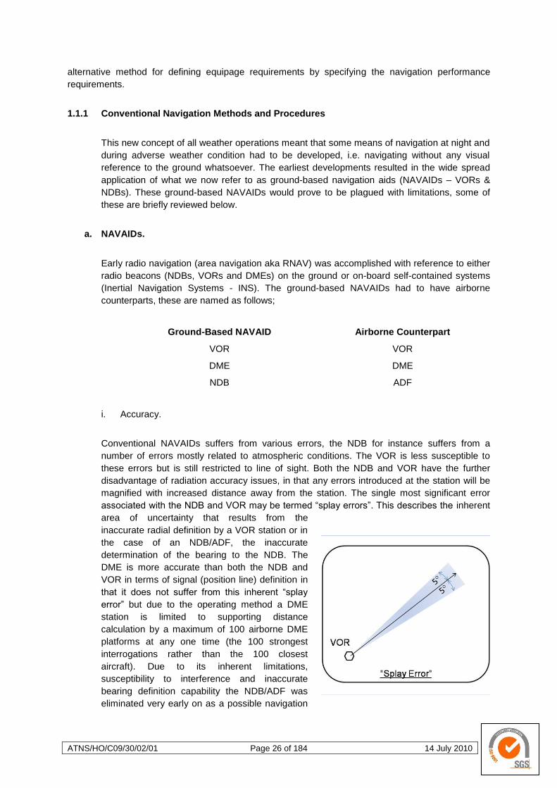
i. Accuracy.
Conventional NAVAIDs suffers from various errors, the NDB for instance suffers from a
number of errors mostly related to atmospheric conditions. The VOR is less susceptible to
these errors but is still restricted to line of sight. Both the NDB and VOR have the further
disadvantage of radiation accuracy issues, in that any errors introduced at the station will be
magnified with increased distance away from the station. The single most significant error
associated with the NDB and VOR may be termed ―splay errors‖. This describes the inherent
area of uncertainty that results from the
inaccurate radial definition by a VOR station or in
the case of an NDB/ADF, the inaccurate
determination of the bearing to the NDB. The
DME is more accurate than both the NDB and
VOR in terms of signal (position line) definition in
that it does not suffer from this inherent ―splay
error‖ but due to the operating method a DME
station is limited to supporting distance
calculation by a maximum of 100 airborne DME
platforms at any one time (the 100 strongest
interrogations rather than the 100 closest
aircraft). Due to its inherent limitations,
susceptibility to interference and inaccurate
bearing definition capability the NDB/ADF was
eliminated very early on as a possible navigation
ATNS/HO/C09/30/02/01 Page 27 of 184 14 July 2010
signal input to any FNC (now referred to as RANV system). To date multiple simultaneous
DME signal inputs to RNAV systems provide the most accurate and cost effective navigation
solution where high accuracy is required from RNAV systems.
ii. Range.
Older NDBs had very limited range while some marine beacons and more modern NDBs are
more powerful. VOR stations may be received at distances as great a 200 NM but at this
distance the lateral accuracy due to the increasing ―splay error effect‖ is much reduced. DME
stations may be used at distances as large as 200 NM and will maintain their accuracy at
maximum range (i.e. DME range arc definition accuracy).
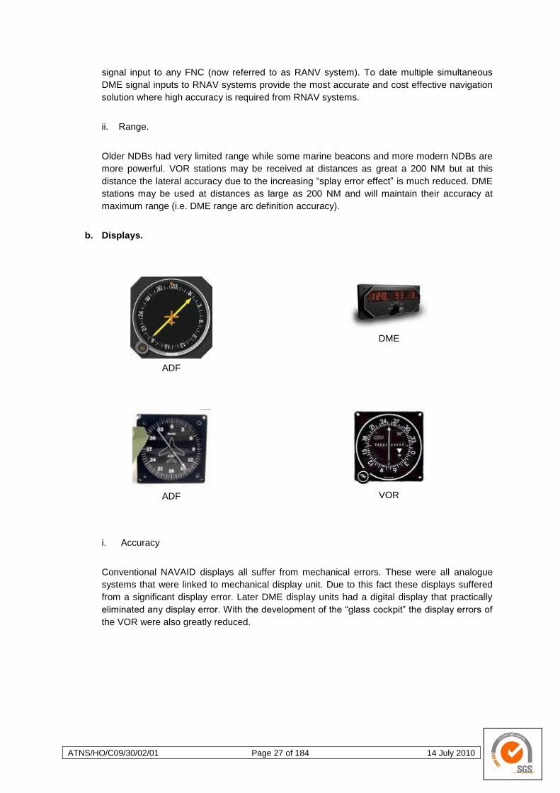
b. Displays.
ADF
DME
ADF
VOR
i. Accuracy
Conventional NAVAID displays all suffer from mechanical errors. These were all analogue
systems that were linked to mechanical display unit. Due to this fact these displays suffered
from a significant display error. Later DME display units had a digital display that practically
eliminated any display error. With the development of the ―glass cockpit‖ the display errors of
the VOR were also greatly reduced.
ATNS/HO/C09/30/02/01 Page 28 of 184 14 July 2010
c. Plotting
Initially a flight navigator would perform a manual
plot using the signals from radio beacons. These
bearings (to an NDB), radials (from a VOR) and
DME range arcs (from a DME ground station)
would be plotted. This process, though not
necessarily difficult but rather mundane and
repetitive, was prone to errors. Lack of attention
to detail by the navigator would result in an
inaccurate plot and thus the aircraft may be
allowed to drift significantly far off course before
an
effective correction was made. Again as a result
of increased operation demand and advances in
technology this manual plotting function would
ultimately be performed by a FNC. The FNC was
able to ensure a repeatable plotting performance,
both in terms of accuracy and reliability. Early
FNCs were not certified in any way but later
application of RNAV saw the introduction of
Required Navigation Performance (RNP)
accuracy as an attempt to standardise and
guarantee the accuracy and repeatability of
accurate navigation performance.
i. Position Fixing
The fundamental aim of navigation is to
accurately, reliably and consistently determine
and/or know the position of an aircraft in flight.
Using navigation signal inputs (NDB, VOR, DME
and GNSS) the accuracy of the plotting solution
is largely determined by the geometry of the plot.
Two position lines (each with an accepted
definition accuracy of 5 - the ICAO standard for
the VOR) will produce a fairly well defined
position. If the same two position line intersected
at a smaller angle, the position will be less well
defined. This position definition will reduce in
clarity as the intersecting angle of the two
position lines reduces.
ATNS/HO/C09/30/02/01 Page 29 of 184 14 July 2010
1.1.2 RNAV Navigation Methods and Procedures
a. Manual Area Navigation (RNAV).
The process performed by a flight navigator whereby the manual tuning of VOR, DME and
ADF frequencies, physical drawing of position lines from ground-based radio beacons on a
plotting chart is carried out, may be termed manual area navigation. This process enables
the navigation of an aircraft along any desired/required track within the coverage area of the
selected and tuned-in navigation radio beacons. The accuracy of this process is affected by a
number of factors and these include but are not limited to the radio beacon signal definition
accuracy and the accuracy of the manual plotting by the navigator. The basic process of
manual plotting is a fairly laborious process and thus will have a limit in terms of its
applicability with an increase in either aircraft speed and/or complexity of route.
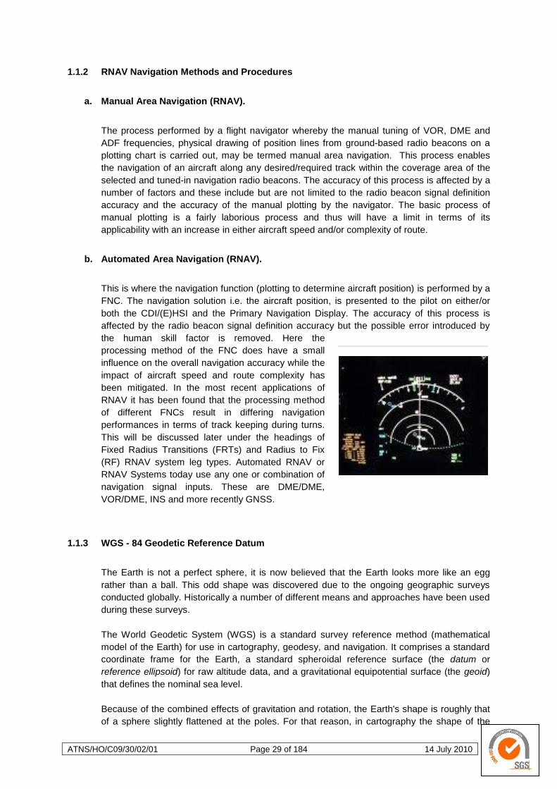
b. Automated Area Navigation (RNAV).
This is where the navigation function (plotting to determine aircraft position) is performed by a
FNC. The navigation solution i.e. the aircraft position, is presented to the pilot on either/or
both the CDI/(E)HSI and the Primary Navigation Display. The accuracy of this process is
affected by the radio beacon signal definition accuracy but the possible error introduced by
the human skill factor is removed. Here the
processing method of the FNC does have a small
influence on the overall navigation accuracy while the
impact of aircraft speed and route complexity has
been mitigated. In the most recent applications of
RNAV it has been found that the processing method
of different FNCs result in differing navigation
performances in terms of track keeping during turns.
This will be discussed later under the headings of
Fixed Radius Transitions (FRTs) and Radius to Fix
(RF) RNAV system leg types. Automated RNAV or
RNAV Systems today use any one or combination of
navigation signal inputs. These are DME/DME,
VOR/DME, INS and more recently GNSS.
1.1.3 WGS - 84 Geodetic Reference Datum
The Earth is not a perfect sphere, it is now believed that the Earth looks more like an egg
rather than a ball. This odd shape was discovered due to the ongoing geographic surveys
conducted globally. Historically a number of different means and approaches have been used
during these surveys.
The World Geodetic System (WGS) is a standard survey reference method (mathematical
model of the Earth) for use in cartography, geodesy, and navigation. It comprises a standard
coordinate frame for the Earth, a standard spheroidal reference surface (the datum or
reference ellipsoid) for raw altitude data, and a gravitational equipotential surface (the geoid)
that defines the nominal sea level.
Because of the combined effects of gravitation and rotation, the Earth's shape is roughly that
of a sphere slightly flattened at the poles. For that reason, in cartography the shape of the

ATNS/HO/C09/30/02/01 Page 30 of 184 14 July 2010
Earth is often approximated by an oblate spheroid instead of a sphere. The current World
Geodetic System model, in particular, uses a spheroid whose radius is approximately
6,378.137 km at the equator and 6,356.752 km at the poles (a difference of over 21 km). The
latest revision is WGS 84 (dating from 1984 and last revised in 2004), which will be valid up to
about 2010. Earlier schemes included WGS 72, WGS 66, and WGS 60. WGS 84 is the
reference coordinate system used by the Global Positioning System. The coordinate origin of
WGS 84 is located at the Earth's centre of mass; the error is believed to be less than 2 cm.
In WGS 84, the meridian of zero longitude is the International Earth Rotation and Reference
Systems Service (IERS) Reference Meridian. It lies 5.31 arc seconds east of the Greenwich
Prime Meridian, which corresponds to 102.5 meters (336.3 feet) at the latitude of the Royal
Observatory. As of the latest revision, the WGS 84 datum surface is a pole-flattened (oblate)
spheroid, with major (transverse) radius a = 6,378,137 m at the equator, and minor
(conjugate) radius b = 6,356,752 m at the poles (a flattening of 21.384 685 755 km, or
1/298.257 223 563 ≈ 0.335% in relative terms). The b parameter is often rounded to
6,356,752.3 m in practical applications.
The 1980 Geodetic Reference System (GRS80) posted a 6,378,137 m semi-major axis and a
1:298.257 flattening. This system was adopted at the XVII General Assembly of the
International Union of Geodesy and Geophysics (IUGG). It is essentially the basis for
geodetic positioning by the Global Positioning System and is thus also in extremely
widespread use outside the geodetic community.
Presently WGS 84 uses the 1996 Earth Gravitational Model (EGM96) geoid, revised in 2004.
The deviations of the EGM96 geoid from the WGS 84 reference ellipsoid range from about -
105 m to about +85 m. EGM96 differs from the original WGS 84 geoid, referred to as EGM84.
In the early 1980s the need for a new world geodetic system was generally recognised by the
geodetic community, also within the US Department of Defence. WGS 72 no longer provided
sufficient data, information, geographic coverage, or product accuracy for all the then current
and anticipated applications. The means for producing a new WGS were available in the form
of improved data, increased data coverage, new data types and improved surveying
techniques. GRS 80 parameters together with available Doppler, satellite laser ranging and
Very Long Baseline Interferometry (VLBI) observations constituted significant new
information. An outstanding new source of data had become available from satellite radar
altimetry. Also available was an advanced least squares method called collocation which
allowed for a consistent combination solution from different types of measurements all relative
to the Earth's gravity field, i.e. geoid, gravity anomalies, deflections, dynamic Doppler, etc.
The WGS 84 originally used the GRS 80 reference ellipsoid, but has undergone some minor
refinements in later editions since its initial publication. Most of these refinements are
important for high-precision orbital calculations for satellites but have little practical effect on
typical topographical uses.
The new World Geodetic System was called WGS 84. It is currently the reference system
being used by the Global Positioning System. It is geocentric and globally consistent within
±1 m. Current geodetic realisations of the geocentric reference system family International
Terrestrial Reference System (ITRS) maintained by the IERS are geocentric, and internally
consistent, at the few-cm level, while still being meter-level consistent with WGS 84.
1.1.4 Historical Overview – Future Air Navigation System (FANS)
Air Traffic Control's ability to monitor aircraft has always been outpaced by the growth of flight
as a mode of travel. In an effort to improve aviation communication, navigation, surveillance,
(CNS) and air traffic management (ATM) the International Civil Aviation Organisation (ICAO)
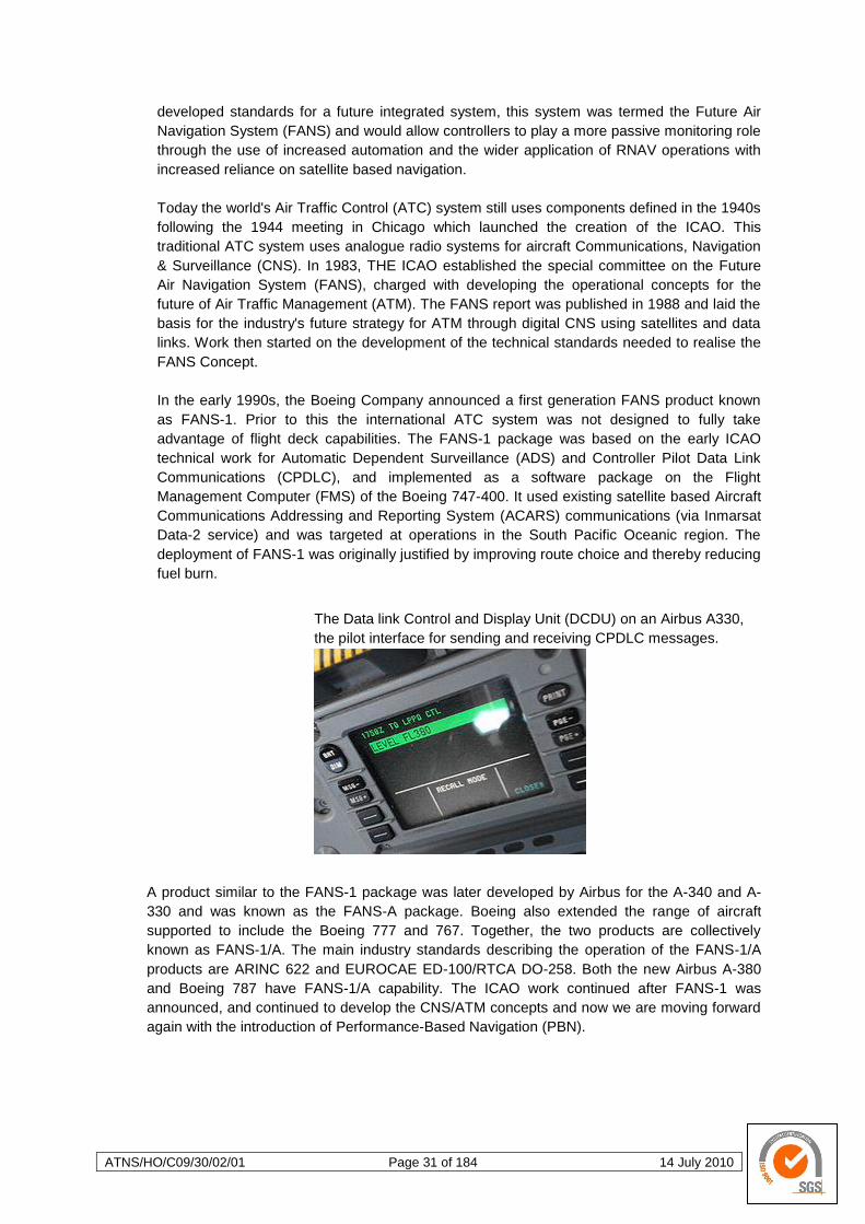
ATNS/HO/C09/30/02/01 Page 31 of 184 14 July 2010
developed standards for a future integrated system, this system was termed the Future Air
Navigation System (FANS) and would allow controllers to play a more passive monitoring role
through the use of increased automation and the wider application of RNAV operations with
increased reliance on satellite based navigation.
Today the world's Air Traffic Control (ATC) system still uses components defined in the 1940s
following the 1944 meeting in Chicago which launched the creation of the ICAO. This
traditional ATC system uses analogue radio systems for aircraft Communications, Navigation
& Surveillance (CNS). In 1983, THE ICAO established the special committee on the Future
Air Navigation System (FANS), charged with developing the operational concepts for the
future of Air Traffic Management (ATM). The FANS report was published in 1988 and laid the
basis for the industry's future strategy for ATM through digital CNS using satellites and data
links. Work then started on the development of the technical standards needed to realise the
FANS Concept.
In the early 1990s, the Boeing Company announced a first generation FANS product known
as FANS-1. Prior to this the international ATC system was not designed to fully take
advantage of flight deck capabilities. The FANS-1 package was based on the early ICAO
technical work for Automatic Dependent Surveillance (ADS) and Controller Pilot Data Link
Communications (CPDLC), and implemented as a software package on the Flight
Management Computer (FMS) of the Boeing 747-400. It used existing satellite based Aircraft
Communications Addressing and Reporting System (ACARS) communications (via Inmarsat
Data-2 service) and was targeted at operations in the South Pacific Oceanic region. The
deployment of FANS-1 was originally justified by improving route choice and thereby reducing
fuel burn.
The Data link Control and Display Unit (DCDU) on an Airbus A330,
the pilot interface for sending and receiving CPDLC messages.
A product similar to the FANS-1 package was later developed by Airbus for the A-340 and A-
330 and was known as the FANS-A package. Boeing also extended the range of aircraft
supported to include the Boeing 777 and 767. Together, the two products are collectively
known as FANS-1/A. The main industry standards describing the operation of the FANS-1/A
products are ARINC 622 and EUROCAE ED-100/RTCA DO-258. Both the new Airbus A-380
and Boeing 787 have FANS-1/A capability. The ICAO work continued after FANS-1 was
announced, and continued to develop the CNS/ATM concepts and now we are moving forward
again with the introduction of Performance-Based Navigation (PBN).
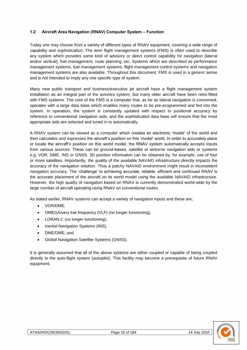
ATNS/HO/C09/30/02/01 Page 32 of 184 14 July 2010
1.2 Aircraft Area Navigation (RNAV) Computer System – Function
Today one may choose from a variety of different types of RNAV equipment, covering a wide range of
capability and sophistication. The term flight management systems (FMS) is often used to describe
any system which provides some kind of advisory or direct control capability for navigation (lateral
and/or vertical), fuel management, route planning, etc. Systems which are described as performance
management systems, fuel management systems, flight management control systems and navigation
management systems are also available. Throughout this document, FMS is used in a generic sense
and is not intended to imply any one specific type of system.
Many new public transport and business/executive jet aircraft have a flight management system
installation as an integral part of the avionics system, but many older aircraft have been retro-fitted
with FMS systems. The core of the FMS is a computer that, as far as lateral navigation is concerned,
operates with a large data base which enables many routes to be pre-programmed and fed into the
system. In operation, the system is constantly updated with respect to positional accuracy by
reference to conventional navigation aids, and the sophisticated data base will ensure that the most
appropriate aids are selected and tuned in to automatically.
A RNAV system can be viewed as a computer which creates an electronic ‗model‘ of the world and
then calculates and expresses the aircraft‘s position on this ‗model‘ world. In order to accurately place
or locate the aircraft‘s position on this world model, the RNAV system automatically accepts inputs
from various sources. These can be ground-based, satellite or airborne navigation aids or systems
e.g. VOR, DME, INS or GNSS. 3D position information can be obtained by, for example, use of four
or more satellites. Importantly, the quality of the available NAVAID infrastructure directly impacts the
accuracy of the navigation solution. Thus a patchy NAVAID environment might result in inconsistent
navigation accuracy. The ‗challenge‘ to achieving accurate, reliable, efficient and continued RNAV is
the accurate placement of the aircraft on its world model using the available NAVAID infrastructure.
However, the high quality of navigation based on RNAV is currently demonstrated world-wide by the
large number of aircraft operating using RNAV on conventional routes.
As stated earlier, RNAV systems can accept a variety of navigation inputs and these are;
VOR/DME,
OMEGA/very low frequency (VLF) (no longer functioning),
LORAN-C (no longer functioning),
Inertial Navigation Systems (INS),
DME/DME; and
Global Navigation Satellite Systems (GNSS).
It is generally assumed that all of the above systems are either coupled or capable of being coupled
directly to the auto-flight system (autopilot). This facility may become a prerequisite of future RNAV
equipment.
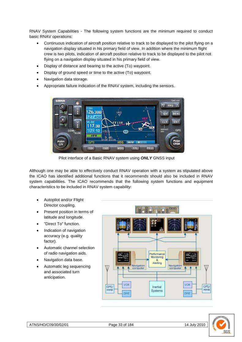
ATNS/HO/C09/30/02/01 Page 33 of 184 14 July 2010
RNAV System Capabilities - The following system functions are the minimum required to conduct
basic RNAV operations:
Continuous indication of aircraft position relative to track to be displayed to the pilot flying on a
navigation display situated in his primary field of view. In addition where the minimum flight
crew is two pilots, indication of aircraft position relative to track to be displayed to the pilot not
flying on a navigation display situated in his primary field of view.
Display of distance and bearing to the active (To) waypoint.
Display of ground speed or time to the active (To) waypoint.
Navigation data storage.
Appropriate failure indication of the RNAV system, including the sensors.
Pilot interface of a Basic RNAV system using ONLY GNSS input
Although one may be able to effectively conduct RNAV operation with a system as stipulated above
the ICAO has identified additional functions that it recommends should also be included in RNAV
system capabilities. The ICAO recommends that the following system functions and equipment
characteristics to be included in RNAV system capability:
Autopilot and/or Flight
Director coupling.
Present position in terms of
latitude and longitude.
"Direct To" function.
Indication of navigation
accuracy (e.g. quality
factor).
Automatic channel selection
of radio navigation aids.
Navigation data base.
Automatic leg sequencing
and associated turn
anticipation.
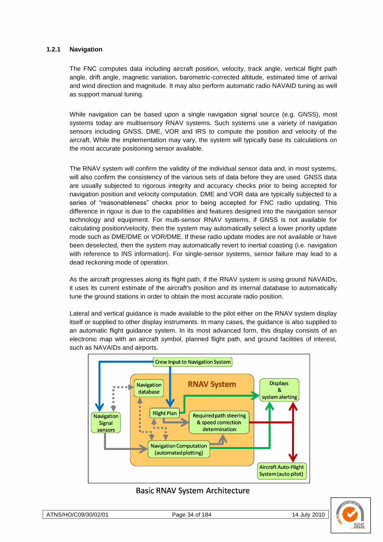
ATNS/HO/C09/30/02/01 Page 34 of 184 14 July 2010
1.2.1 Navigation
The FNC computes data including aircraft position, velocity, track angle, vertical flight path
angle, drift angle, magnetic variation, barometric-corrected altitude, estimated time of arrival
and wind direction and magnitude. It may also perform automatic radio NAVAID tuning as well
as support manual tuning.
While navigation can be based upon a single navigation signal source (e.g. GNSS), most
systems today are multisensory RNAV systems. Such systems use a variety of navigation
sensors including GNSS, DME, VOR and IRS to compute the position and velocity of the
aircraft. While the implementation may vary, the system will typically base its calculations on
the most accurate positioning sensor available.
The RNAV system will confirm the validity of the individual sensor data and, in most systems,
will also confirm the consistency of the various sets of data before they are used. GNSS data
are usually subjected to rigorous integrity and accuracy checks prior to being accepted for
navigation position and velocity computation. DME and VOR data are typically subjected to a
series of ―reasonableness‖ checks prior to being accepted for FNC radio updating. This
difference in rigour is due to the capabilities and features designed into the navigation sensor
technology and equipment. For multi-sensor RNAV systems, if GNSS is not available for
calculating position/velocity, then the system may automatically select a lower priority update
mode such as DME/DME or VOR/DME. If these radio update modes are not available or have
been deselected, then the system may automatically revert to inertial coasting (i.e. navigation
with reference to INS information). For single-sensor systems, sensor failure may lead to a
dead reckoning mode of operation.
As the aircraft progresses along its flight path, if the RNAV system is using ground NAVAIDs,
it uses its current estimate of the aircraft's position and its internal database to automatically
tune the ground stations in order to obtain the most accurate radio position.
Lateral and vertical guidance is made available to the pilot either on the RNAV system display
itself or supplied to other display instruments. In many cases, the guidance is also supplied to
an automatic flight guidance system. In its most advanced form, this display consists of an
electronic map with an aircraft symbol, planned flight path, and ground facilities of interest,
such as NAVAIDs and airports.
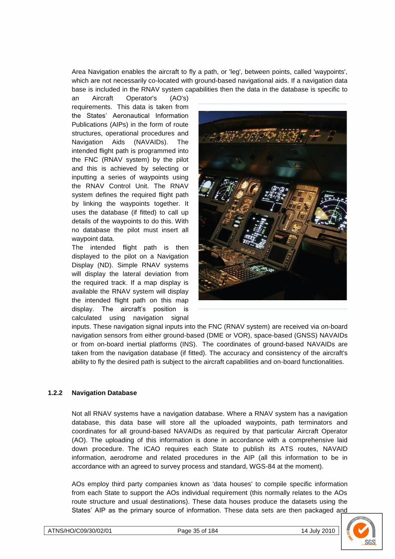
ATNS/HO/C09/30/02/01 Page 35 of 184 14 July 2010
Area Navigation enables the aircraft to fly a path, or 'leg', between points, called 'waypoints',
which are not necessarily co-located with ground-based navigational aids. If a navigation data
base is included in the RNAV system capabilities then the data in the database is specific to
an Aircraft Operator's (AO's)
requirements. This data is taken from
the States‘ Aeronautical Information
Publications (AIPs) in the form of route
structures, operational procedures and
Navigation Aids (NAVAIDs). The
intended flight path is programmed into
the FNC (RNAV system) by the pilot
and this is achieved by selecting or
inputting a series of waypoints using
the RNAV Control Unit. The RNAV
system defines the required flight path
by linking the waypoints together. It
uses the database (if fitted) to call up
details of the waypoints to do this. With
no database the pilot must insert all
waypoint data.
The intended flight path is then
displayed to the pilot on a Navigation
Display (ND). Simple RNAV systems
will display the lateral deviation from
the required track. If a map display is
available the RNAV system will display
the intended flight path on this map
display. The aircraft‘s position is
calculated using navigation signal
inputs. These navigation signal inputs into the FNC (RNAV system) are received via on-board
navigation sensors from either ground-based (DME or VOR), space-based (GNSS) NAVAIDs
or from on-board inertial platforms (INS). The coordinates of ground-based NAVAIDs are
taken from the navigation database (if fitted). The accuracy and consistency of the aircraft's
ability to fly the desired path is subject to the aircraft capabilities and on-board functionalities.
1.2.2 Navigation Database
Not all RNAV systems have a navigation database. Where a RNAV system has a navigation
database, this data base will store all the uploaded waypoints, path terminators and
coordinates for all ground-based NAVAIDs as required by that particular Aircraft Operator
(AO). The uploading of this information is done in accordance with a comprehensive laid
down procedure. The ICAO requires each State to publish its ATS routes, NAVAID
information, aerodrome and related procedures in the AIP (all this information to be in
accordance with an agreed to survey process and standard, WGS-84 at the moment).
AOs employ third party companies known as 'data houses' to compile specific information
from each State to support the AOs individual requirement (this normally relates to the AOs
route structure and usual destinations). These data houses produce the datasets using the
States‘ AIP as the primary source of information. These data sets are then packaged and
ATNS/HO/C09/30/02/01 Page 36 of 184 14 July 2010
shipped in ARINC 424 format to the Original Equipment (RNAV system) Manufacturers
(OEMs). The OEMs are known as 'data packers' and they then code and then upload the
datasets into the appropriate (target) RNAV systems. The data bases are updated and
validated in accordance with
the ICAO AIRAC
cycle. There are several
manufacturers of RNAV
systems and the formats
used by these systems are
different. Furthermore, no
two AOs will require exactly
the same information. Some
AOs will create company
routes (a pre-defined series
of waypoints) to enable
quicker uploads of specific
routes.
If the data in the dataset is
incorrect, the data in the
database will be incorrect
and the pilot may not be
aware of this. Good
airmanship dictates that the
flight path extracted from the
database be checked for
accuracy and consistency
against the chart information
before and during operation.
When using a RNAV system
with a database, the pilot will
select the ―company route‖
or the waypoints defining the
flight planned route in turn
from the database to create a route in the FNC (RNAV system). The pilot is unable to change
the navigation data in the database. This is a system design characteristic built into the
system to avoid risk of data corruption in the uploaded dataset. Most RNAV systems available
today include the ability to access a navigation database containing the waypoints, routes,
speeds and altitudes for published instrument flight procedures.
For RNAV systems without a database, the pilot is required to manually insert the waypoints
(key in the coordinates of each waypoint required to define the route). Systems with this
functionality will be limited in the navigation specifications that the aircraft can meet.
ATNS/HO/C09/30/02/01 Page 37 of 184 14 July 2010
1.2.3 Flight Planning
The flight planning function creates and assembles the lateral and vertical flight plan used by
the guidance function. A key aspect of the flight plan is the specification of flight plan
waypoints using latitude and longitude, without reference to the location of any ground
navigation aids.
More advanced RNAV systems include a capability for performance management where
aerodynamic and propulsion models are used to compute vertical flight profiles matched to
the aircraft and able to satisfy the constraints imposed by air traffic control. A performance
management function can be complex, utilising fuel flow, total fuel, flap position, engine data
and limits, altitude, airspeed, Mach, temperature, vertical speed, progress along the flight plan
and pilot inputs.
RNAV systems routinely provide flight progress information for the waypoints en-route, for
terminal and approach procedures, and the origin and destination. The information includes
estimated time of arrival, and distance-to-go which are both useful in tactical and planning
coordination with ATC
Manual or automated notification of an aircraft‘s qualification to operate along an ATS route,
on a procedure or in a particular portion of airspace is provided to ATC via the Flight Plan.
Flight Plan procedures are addressed in Procedures for Air Navigation Services — Air Traffic
Management (PANS-ATM) (Doc 4444).
1.2.4 Guidance and Control
A RNAV system provides lateral guidance, and in many cases, vertical guidance as well. The
lateral guidance function compares the aircraft‘s position generated by the navigation function
with the desired lateral flight path and then generates steering commands used to fly the
aircraft along the desired path. Geodesic or great circle paths joining the flight plan waypoints,
typically known as ―legs‖, and circular transition arcs between these legs are calculated by the
RNAV system. The flight path error is computed by comparing the aircraft‘s present position
and direction with the reference path. Roll steering commands to track the reference path are
based upon the path error. These steering commands are output to a flight guidance system,
which either controls the aircraft directly or generates commands for the flight director. The
vertical guidance function, where included, is used to control the aircraft along the vertical
profile within constraints imposed by the flight plan. The outputs of the vertical guidance
function are typically pitch commands to a display and/or flight guidance system, and thrust or
speed commands to displays and/or an auto-thrust function.
The difference between the required (ATS defined) and defined (RNAV system) paths, and
especially the ability to ―follow‖ required (ATS Defined) fixed path turns, depend on but is not
limited to:
the accuracy of the initial AIP navigation data as supplied by the State,
the coding accuracy of the dataset by the data packers,
the accuracy and quality of the navigation signals inputs,
the accuracy of the on-board navigation sensors,
the capabilities, functionalities and processing methodology of the RNAV system,
and/or,
the manual/Flight Director/autopilot control accuracy of the aircraft.
ATNS/HO/C09/30/02/01 Page 38 of 184 14 July 2010
1.2.5 Display and System Control
Display and system controls provide the means for system initialisation, flight planning, path
deviations, progress monitoring, active guidance control and presentation of navigation data
for flight crew situational awareness.
Garmin 530
RNAV system using GNSS, VOR, DME
and ILS input.
Garmin 430 RNAV
system using GNSS, VOR, DME and ILS
input.
FMS
Primary Navigation Display
In complex RNAV systems control is via FMS key pad and in basic systems via the CDU.
1.2.6 Manual Radio Position Updating
In older RNAV systems the INS position is programmed in by a flight crew member, this takes
time and is vulnerable to input errors. This position update is normally done during or just
prior to engine start-up. The INS position may also require manual position updating by a
crew member and if so, this type of system is limited in its application.
1.2.7 Automatic Radio Position Updating
More modern systems will update the INS position automatically using aircraft position
entered into the FMS by the crew during FMS initialisation, by conventional NAVAIDs, GBAS
or GRAS.
ATNS/HO/C09/30/02/01 Page 39 of 184 14 July 2010
1.3 Area Navigation (RNAV) Operations
In South Africa RNAV operations have been successfully implemented for the en-route phase
of flight between the three major city pairs as well as between Johannesburg and the major
coastal cities. We are now at the start of the process to expand this RNAV application into the
TMAs and the PBN implementation project will be the vehicle that will enable this expansion.
1.3.1 RNAV Routes
Volume II of the PBN Manual addresses the different Navigation Specifications which are
suited to one or more phases of flight.
a. EN-ROUTE:
Oceanic/Remote Continental
Continental
b. TERMINAL AIRSPACE:
Arrival/Departures
Approach:
o standard (RNP APCH) with or without vertical guidance, which everyone can fly, or
o demanding (RNP AR APCH) requiring specific approval, functionality and training.
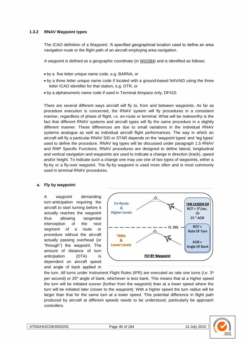
ATNS/HO/C09/30/02/01 Page 40 of 184 14 July 2010
1.3.2 RNAV Waypoint types
The ICAO definition of a Waypoint: ‗A specified geographical location used to define an area
navigation route or the flight path of an aircraft employing area navigation.
A waypoint is defined as a geographic coordinate (in WGS84) and is identified as follows;
by a five letter unique name code, e.g. BARNA, or
by a three letter unique name code if located with a ground-based NAVAID using the three
letter ICAO identifier for that station, e.g. OTR, or
by a alphanumeric name code if used in Terminal Airspace only, DF410.
There are several different ways aircraft will fly to, from and between waypoints. As far as
procedure execution is concerned, the RNAV system will fly procedures in a consistent
manner, regardless of phase of flight, i.e. en-route or terminal. What will be noteworthy is the
fact that different RNAV systems and aircraft types will fly the same procedure in a slightly
different manner. These differences are due to small variations in the individual RNAV
systems analogue as well as individual aircraft flight performances. The way in which an
aircraft will fly a particular RNAV SID or STAR depends on the ‗waypoint types‘ and ‗leg types‘
used to define the procedure. RNAV leg types will be discussed under paragraph 1.5 RNAV
and RNP Specific Functions. RNAV procedures are designed to define lateral, longitudinal
and vertical navigation and waypoints are used to indicate a change in direction (track), speed
and/or height. To indicate such a change one may use one of two types of waypoints, either a
fly-by or a fly-over waypoint. The fly-by waypoint is used more often and is most commonly
used in terminal RNAV procedures.
a. Fly by waypoint:
A waypoint demanding
turn anticipation requiring the
aircraft to start turning before it
actually reaches the waypoint
thus allowing tangential
interception of the next
segment of a route or
procedure without the aircraft
actually passing overhead (or
―through‖) the waypoint. The
amount of distance of turn
anticipation (DTA) is
dependent on aircraft speed
and angle of back applied in
the turn. All turns under Instrument Flight Rules (IFR) are executed as rate one turns (i.e. 3
per second) or 25 angle of bank, whichever is less bank. This means that at a higher speed
the turn will be initiated sooner (further from the waypoint) than at a lower speed where the
turn will be initiated later (closer to the waypoint). With a higher speed the turn radius will be
larger than that for the same turn at a lower speed. This potential difference in flight path
produced by aircraft at different speeds needs to be understood, particularly be approach
controllers.
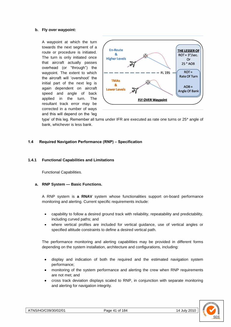
ATNS/HO/C09/30/02/01 Page 41 of 184 14 July 2010
b. Fly over waypoint:
A waypoint at which the turn
towards the next segment of a
route or procedure is initiated.
The turn is only initiated once
that aircraft actually passes
overhead (or ―through‖) the
waypoint. The extent to which
the aircraft will ‗overshoot‘ the
initial part of the next leg is
again dependent on aircraft
speed and angle of back
applied in the turn. The
resultant track error may be
corrected in a number of ways
and this will depend on the ‗leg
type‘ of this leg. Remember all turns under IFR are executed as rate one turns or 25 angle of
bank, whichever is less bank.
1.4 Required Navigation Performance (RNP) – Specification
1.4.1 Functional Capabilities and Limitations
Functional Capabilities.
a. RNP System — Basic Functions.
A RNP system is a RNAV system whose functionalities support on-board performance
monitoring and alerting. Current specific requirements include:
capability to follow a desired ground track with reliability, repeatability and predictability,
including curved paths; and
where vertical profiles are included for vertical guidance, use of vertical angles or
specified altitude constraints to define a desired vertical path.
The performance monitoring and alerting capabilities may be provided in different forms
depending on the system installation, architecture and configurations, including:
display and indication of both the required and the estimated navigation system
performance;
monitoring of the system performance and alerting the crew when RNP requirements
are not met; and
cross track deviation displays scaled to RNP, in conjunction with separate monitoring
and alerting for navigation integrity.
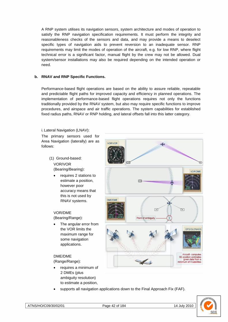
ATNS/HO/C09/30/02/01 Page 42 of 184 14 July 2010
A RNP system utilises its navigation sensors, system architecture and modes of operation to
satisfy the RNP navigation specification requirements. It must perform the integrity and
reasonableness checks of the sensors and data, and may provide a means to deselect
specific types of navigation aids to prevent reversion to an inadequate sensor. RNP
requirements may limit the modes of operation of the aircraft, e.g. for low RNP, where flight
technical error is a significant factor, manual flight by the crew may not be allowed. Dual
system/sensor installations may also be required depending on the intended operation or
need.
b. RNAV and RNP Specific Functions.
Performance-based flight operations are based on the ability to assure reliable, repeatable
and predictable flight paths for improved capacity and efficiency in planned operations. The
implementation of performance-based flight operations requires not only the functions
traditionally provided by the RNAV system, but also may require specific functions to improve
procedures, and airspace and air traffic operations. The system capabilities for established
fixed radius paths, RNAV or RNP holding, and lateral offsets fall into this latter category.
i. Lateral Navigation (LNAV):
The primary sensors used for
Area Navigation (laterally) are as
follows:
(1) Ground-based:
VOR/VOR
(Bearing/Bearing):
requires 2 stations to
estimate a position,
however poor
accuracy means that
this is not used by
RNAV systems.
VOR/DME
(Bearing/Range):
The angular error from
the VOR limits the
maximum range for
some navigation
applications.
DME/DME
(Range/Range):
requires a minimum of
2 DMEs (plus
ambiguity resolution)
to estimate a position,
supports all navigation applications down to the Final Approach Fix (FAF).
ATNS/HO/C09/30/02/01 Page 43 of 184 14 July 2010
(2) Space -based:
GPS and possibly GLONASS (once it becomes fully operational again):
a 3D position solution is calculated by estimating the range from 4 satellites.
ii. Vertical Navigation (VNAV):
(although briefly mentioned here, VNAV will be discussed in more detail under All Weather
Operations, Sensor Specific RNAV Procedures, Para 3.3.3.a, page 114)
There are 2 systems identified to support vertical navigation:
Barometric Altimetry - BARO VNAV:
Barometric Altimetry provides readings based on atmospheric pressure
(temperature dependant). The approach path will become shallower in colder
temperatures and steeper in higher temperatures.
Geometric Altimetry:
Geometric Altimetry is provided by GNSS. However, vertical accuracy of raw GPS is
insufficient for aviation applications. Therefore, other systems have been developed
to overcome this.
c. RNAV System Limitations.
There are also potential disadvantages to using RNAV in the terminal area:
Controllers will need to provide services to both RNAV and non-RNAV aircraft within
the same airspace.
RNAV databases and equipment are not fully standardised, and there is no firm
guidance on how the information is processed by aircraft systems. Tracks may be
flown slightly differently due to equipment, pilot technique or airline policies. However,
these track differences should not be significant enough to appear as deviations from
the published procedure.
Initially, controllers may be uncertain of the expected aircraft behaviour during a
RNAV turn, which may result in unnecessary vectors.
A common factor in each case is that RNAV procedures in the terminal area are relatively
new. Over time the number of RNAV operations will increase. Good procedure design,
effective training, and experience with terminal RNAV will increase pilot and controller
confidence in RNAV procedures.
1.4.2 RNAV System Requirements in terms of Accuracy, Integrity and continuity
a. RNAV Accuracy.
The precision with which a RNAV procedure is flown depends on the navigation source and
on the aircraft onboard equipment and database. Even though a standard format exists (i.e.,
ARINC 424), the coding of a RNAV SID or STAR into a database (or the interpretation of that
coding) may vary slightly. Differences in the databases along with variations in aircraft
performance may result in slightly different tracks being flown by RNAV capable aircraft on
the same procedure. This will be most apparent during turns and where fly-over waypoints

ATNS/HO/C09/30/02/01 Page 44 of 184 14 July 2010
are used. Tracking of a defined path by a RNAV capable aircraft is as accurate as, or better
than, that of aircraft flying conventional routes. In fact RNAV is often used to fly conventional
en route and terminal procedures
PBN operations require (lateral)
accuracy, integrity, continuity,
and availability of aircraft
systems together with particular
RNAV computer functionalities
to meet specific requirements.
These requirements are defined
for a particular Navigation
Application in the associated
Navigation Specification.
The lateral track accuracy is
defined by:
the path that has been
defined by the RNAV
system,
the navigation sensor used to estimate the position, and
the ability of the pilot and system to fly the defined path.
If the pilot or system is unable to maintain the defined path, this is known as the Flight
Technical Error (FTE). The performance limits for the FTE are laid down by the ICAO for each
RNP Specification. Position estimation accuracy is related to the type of navigation sensor
used; each sensor has its own error value,
called the ‗Navigation Sensor Error‘ (NSE).
It is also linked to the ‗dilution of precision'
(DOP). DOP is dependent upon the
relative angle the signals subtend at the
aircraft (angle of cut) and can be
considered the uncertainty in position
estimation.
Some sensors are better suited to RNAV
(PBN) operations than others:
NDB: is not an input to RNAV systems.
VOR: at long range is the least accurate of
the ground-based NAVAIDs used in Area
Navigation, it is too inaccurate for the more
demanding lateral track accuracy
requirements.
DME: providing there are sufficient stations
with appropriate geometry, supports most
Navigation Applications up to a simple
approach the accuracy of a DME/DME
position estimation is too poor when the
DOP of the signals from a pair of stations subtend less than 30° and more than 150°.
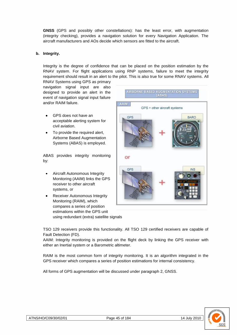
ATNS/HO/C09/30/02/01 Page 45 of 184 14 July 2010
GNSS (GPS and possibly other constellations): has the least error, with augmentation
(integrity checking), provides a navigation solution for every Navigation Application. The
aircraft manufacturers and AOs decide which sensors are fitted to the aircraft.
b. Integrity.
Integrity is the degree of confidence that can be placed on the position estimation by the
RNAV system. For flight applications using RNP systems, failure to meet the integrity
requirement should result in an alert to the pilot. This is also true for some RNAV systems. All
RNAV Systems using GPS as primary
navigation signal input are also
designed to provide an alert in the
event of navigation signal input failure
and/or RAIM failure.
GPS does not have an
acceptable alerting system for
civil aviation.
To provide the required alert,
Airborne Based Augmentation
Systems (ABAS) is employed.
ABAS provides integrity monitoring
by:
Aircraft Autonomous Integrity
Monitoring (AAIM) links the GPS
receiver to other aircraft
systems, or
Receiver Autonomous Integrity
Monitoring (RAIM), which
compares a series of position
estimations within the GPS unit
using redundant (extra) satellite signals
TSO 129 receivers provide this functionality. All TSO 129 certified receivers are capable of
Fault Detection (FD).
AAIM: Integrity monitoring is provided on the flight deck by linking the GPS receiver with
either an Inertial system or a Barometric altimeter.
RAIM is the most common form of integrity monitoring. It is an algorithm integrated in the
GPS receiver which compares a series of position estimations for internal consistency.
All forms of GPS augmentation will be discussed under paragraph 2, GNSS.
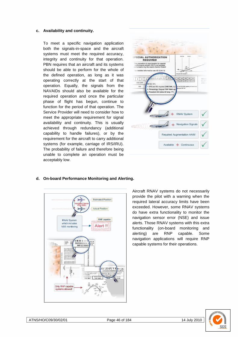
ATNS/HO/C09/30/02/01 Page 46 of 184 14 July 2010
c. Availability and continuity.
To meet a specific navigation application
both the signals-in-space and the aircraft
systems must meet the required accuracy,
integrity and continuity for that operation.
PBN requires that an aircraft and its systems
should be able to perform for the whole of
the defined operation, as long as it was
operating correctly at the start of that
operation. Equally, the signals from the
NAVAIDs should also be available for the
required operation and once the particular
phase of flight has begun, continue to
function for the period of that operation. The
Service Provider will need to consider how to
meet the appropriate requirement for signal
availability and continuity. This is usually
achieved through redundancy (additional
capability to handle failures), or by the
requirement for the aircraft to carry additional
systems (for example, carriage of IRS/IRU).
The probability of failure and therefore being
unable to complete an operation must be
acceptably low.
d. On-board Performance Monitoring and Alerting.
Aircraft RNAV systems do not necessarily
provide the pilot with a warning when the
required lateral accuracy limits have been
exceeded. However, some RNAV systems
do have extra functionality to monitor the
navigation sensor error (NSE) and issue
alerts. Those RNAV systems with this extra
functionality (on-board monitoring and
alerting) are RNP capable. Some
navigation applications will require RNP
capable systems for their operations.
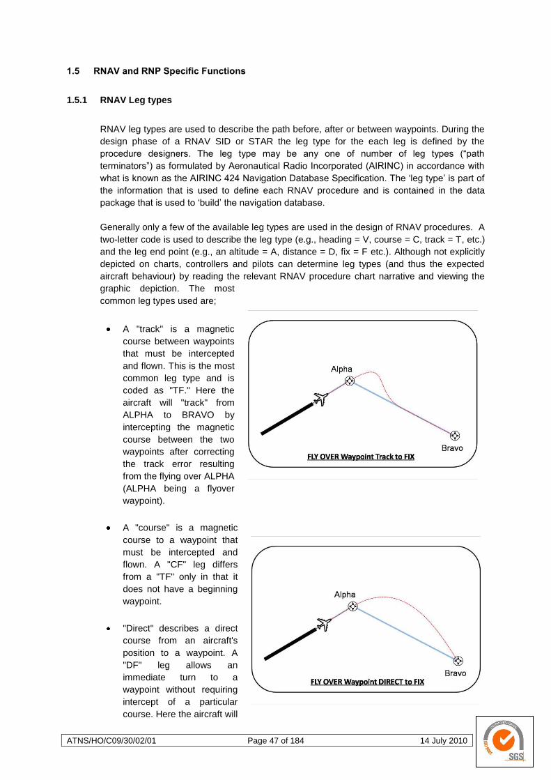
ATNS/HO/C09/30/02/01 Page 47 of 184 14 July 2010
1.5 RNAV and RNP Specific Functions
1.5.1 RNAV Leg types
RNAV leg types are used to describe the path before, after or between waypoints. During the
design phase of a RNAV SID or STAR the leg type for the each leg is defined by the
procedure designers. The leg type may be any one of number of leg types (―path
terminators‖) as formulated by Aeronautical Radio Incorporated (AIRINC) in accordance with
what is known as the AIRINC 424 Navigation Database Specification. The ‗leg type‘ is part of
the information that is used to define each RNAV procedure and is contained in the data
package that is used to ‗build‘ the navigation database.
Generally only a few of the available leg types are used in the design of RNAV procedures. A
two-letter code is used to describe the leg type (e.g., heading = V, course = C, track = T, etc.)
and the leg end point (e.g., an altitude = A, distance = D, fix = F etc.). Although not explicitly
depicted on charts, controllers and pilots can determine leg types (and thus the expected
aircraft behaviour) by reading the relevant RNAV procedure chart narrative and viewing the
graphic depiction. The most
common leg types used are;
A "track" is a magnetic
course between waypoints
that must be intercepted
and flown. This is the most
common leg type and is
coded as "TF." Here the
aircraft will "track" from
ALPHA to BRAVO by
intercepting the magnetic
course between the two
waypoints after correcting
the track error resulting
from the flying over ALPHA
(ALPHA being a flyover
waypoint).
A "course" is a magnetic
course to a waypoint that
must be intercepted and
flown. A "CF" leg differs
from a "TF" only in that it
does not have a beginning
waypoint.
"Direct" describes a direct
course from an aircraft's
position to a waypoint. A
"DF" leg allows an
immediate turn to a
waypoint without requiring
intercept of a particular
course. Here the aircraft will

ATNS/HO/C09/30/02/01 Page 48 of 184 14 July 2010
proceed "direct" to BRAVO after crossing the fly-over waypoint ALPHA.
A "heading" is a magnetic heading to be flown. Heading legs are subject to wind drift. A
"VA" leg is a heading to an altitude and a "VM" is a heading to a "manual termination."
The "VA" leg is often used as the first leg of a RNAV departure. The "VM" leg is most
often used to end a RNAV STAR on, for example, a downwind leg heading.
Below we see the combination of a VA, CF, and TF that has been used to create the initial
portion of a RNAV SID.
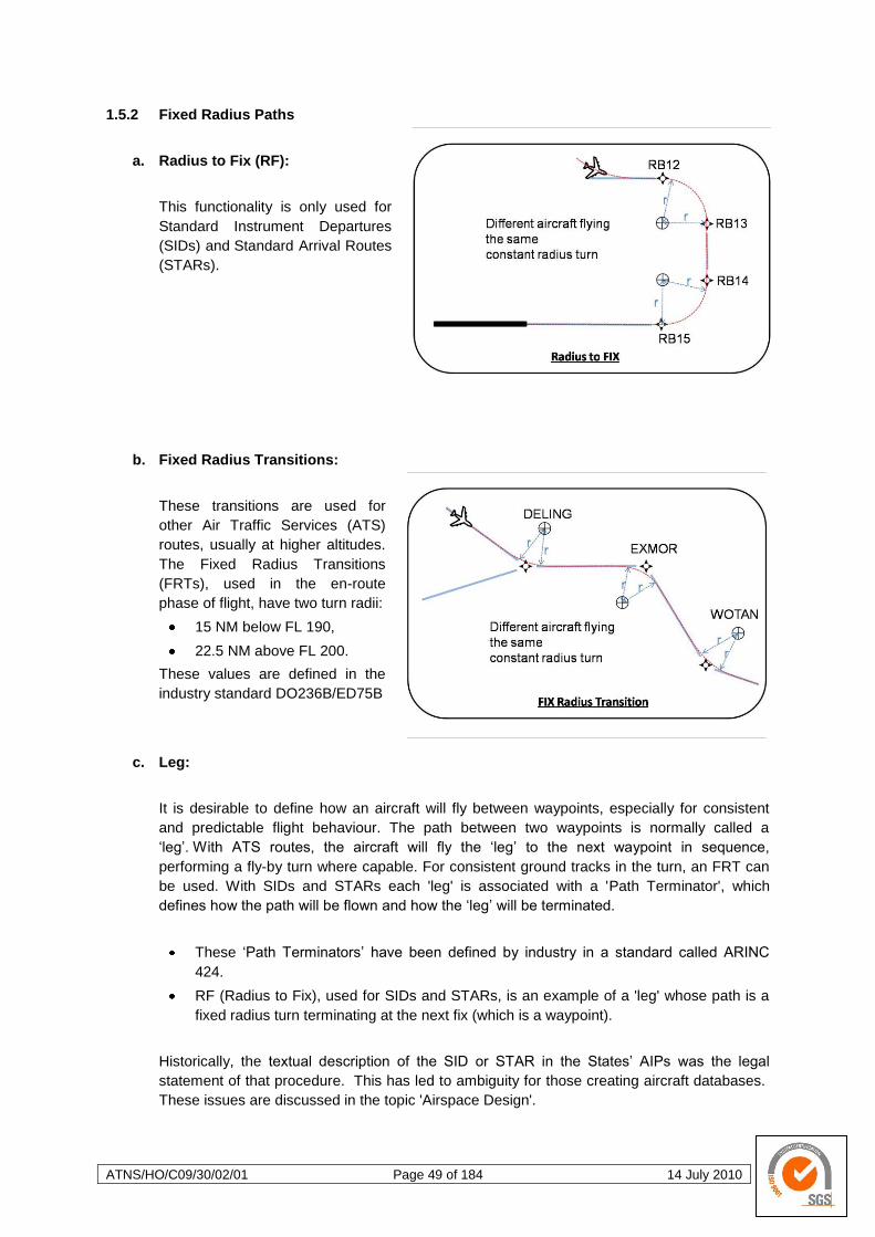
ATNS/HO/C09/30/02/01 Page 49 of 184 14 July 2010
1.5.2 Fixed Radius Paths
a. Radius to Fix (RF):
This functionality is only used for
Standard Instrument Departures
(SIDs) and Standard Arrival Routes
(STARs).
b. Fixed Radius Transitions:
These transitions are used for
other Air Traffic Services (ATS)
routes, usually at higher altitudes.
The Fixed Radius Transitions
(FRTs), used in the en-route
phase of flight, have two turn radii:
15 NM below FL 190,
22.5 NM above FL 200.
These values are defined in the
industry standard DO236B/ED75B
c. Leg:
It is desirable to define how an aircraft will fly between waypoints, especially for consistent
and predictable flight behaviour. The path between two waypoints is normally called a
‗leg‘. With ATS routes, the aircraft will fly the ‗leg‘ to the next waypoint in sequence,
performing a fly-by turn where capable. For consistent ground tracks in the turn, an FRT can
be used. With SIDs and STARs each 'leg' is associated with a 'Path Terminator', which
defines how the path will be flown and how the ‗leg‘ will be terminated.
These ‗Path Terminators‘ have been defined by industry in a standard called ARINC
424.
RF (Radius to Fix), used for SIDs and STARs, is an example of a 'leg' whose path is a
fixed radius turn terminating at the next fix (which is a waypoint).
Historically, the textual description of the SID or STAR in the States‘ AIPs was the legal
statement of that procedure. This has led to ambiguity for those creating aircraft databases.
These issues are discussed in the topic 'Airspace Design'.
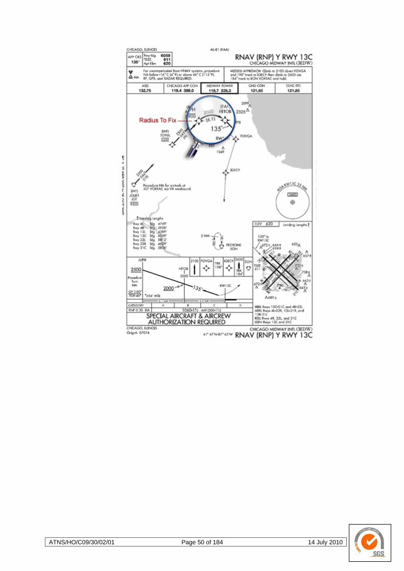
ATNS/HO/C09/30/02/01 Page 50 of 184 14 July 2010
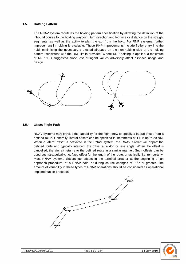
ATNS/HO/C09/30/02/01 Page 51 of 184 14 July 2010
1.5.3 Holding Pattern
The RNAV system facilitates the holding pattern specification by allowing the definition of the
inbound course to the holding waypoint, turn direction and leg time or distance on the straight
segments, as well as the ability to plan the exit from the hold. For RNP systems, further
improvement in holding is available. These RNP improvements include fly-by entry into the
hold, minimising the necessary protected airspace on the non-holding side of the holding
pattern, consistent with the RNP limits provided. Where RNP holding is applied, a maximum
of RNP 1 is suggested since less stringent values adversely affect airspace usage and
design.
1.5.4 Offset Flight Path
RNAV systems may provide the capability for the flight crew to specify a lateral offset from a
defined route. Generally, lateral offsets can be specified in increments of 1 NM up to 20 NM.
When a lateral offset is activated in the RNAV system, the RNAV aircraft will depart the
defined route and typically intercept the offset at a 45⁰ or less angle. When the offset is
cancelled, the aircraft returns to the defined route in a similar manner. Such offsets can be
used both strategically, i.e. fixed offset for the length of the route, or tactically, i.e. temporarily.
Most RNAV systems discontinue offsets in the terminal area or at the beginning of an
approach procedure, at a RNAV hold, or during course changes of 90⁰s or greater. The
amount of variability in these types of RNAV operations should be considered as operational
implementation proceeds.
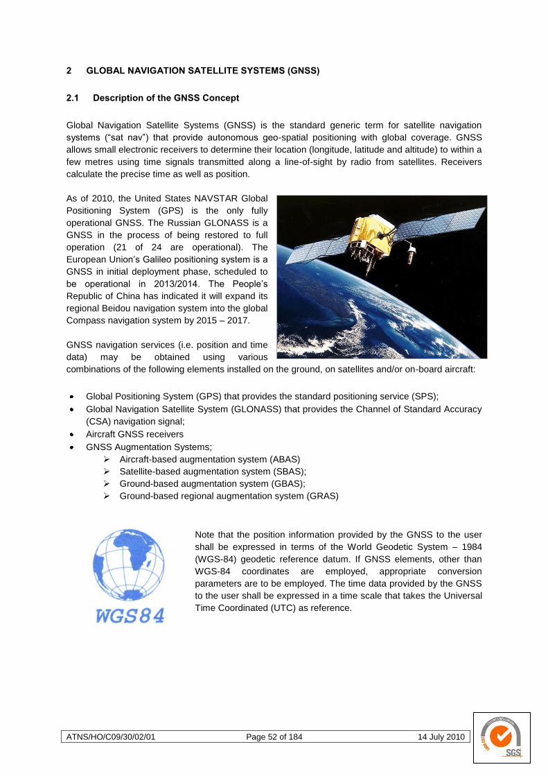
ATNS/HO/C09/30/02/01 Page 52 of 184 14 July 2010
2 GLOBAL NAVIGATION SATELLITE SYSTEMS (GNSS)
2.1 Description of the GNSS Concept
Global Navigation Satellite Systems (GNSS) is the standard generic term for satellite navigation
systems (―sat nav‖) that provide autonomous geo-spatial positioning with global coverage. GNSS
allows small electronic receivers to determine their location (longitude, latitude and altitude) to within a
few metres using time signals transmitted along a line-of-sight by radio from satellites. Receivers
calculate the precise time as well as position.
As of 2010, the United States NAVSTAR Global
Positioning System (GPS) is the only fully
operational GNSS. The Russian GLONASS is a
GNSS in the process of being restored to full
operation (21 of 24 are operational). The
European Union‘s Galileo positioning system is a
GNSS in initial deployment phase, scheduled to
be operational in 2013/2014. The People‘s
Republic of China has indicated it will expand its
regional Beidou navigation system into the global
Compass navigation system by 2015 – 2017.
GNSS navigation services (i.e. position and time
data) may be obtained using various
combinations of the following elements installed on the ground, on satellites and/or on-board aircraft:
Global Positioning System (GPS) that provides the standard positioning service (SPS);
Global Navigation Satellite System (GLONASS) that provides the Channel of Standard Accuracy
(CSA) navigation signal;
Aircraft GNSS receivers
GNSS Augmentation Systems;
Aircraft-based augmentation system (ABAS)
Satellite-based augmentation system (SBAS);
Ground-based augmentation system (GBAS);
Ground-based regional augmentation system (GRAS)
Note that the position information provided by the GNSS to the user
shall be expressed in terms of the World Geodetic System – 1984
(WGS-84) geodetic reference datum. If GNSS elements, other than
WGS-84 coordinates are employed, appropriate conversion
parameters are to be employed. The time data provided by the GNSS
to the user shall be expressed in a time scale that takes the Universal
Time Coordinated (UTC) as reference.
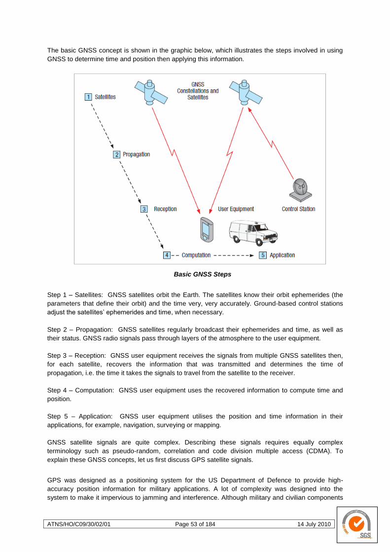
ATNS/HO/C09/30/02/01 Page 53 of 184 14 July 2010
The basic GNSS concept is shown in the graphic below, which illustrates the steps involved in using
GNSS to determine time and position then applying this information.
Basic GNSS Steps
Step 1 – Satellites: GNSS satellites orbit the Earth. The satellites know their orbit ephemerides (the
parameters that define their orbit) and the time very, very accurately. Ground-based control stations
adjust the satellites‘ ephemerides and time, when necessary.
Step 2 – Propagation: GNSS satellites regularly broadcast their ephemerides and time, as well as
their status. GNSS radio signals pass through layers of the atmosphere to the user equipment.
Step 3 – Reception: GNSS user equipment receives the signals from multiple GNSS satellites then,
for each satellite, recovers the information that was transmitted and determines the time of
propagation, i.e. the time it takes the signals to travel from the satellite to the receiver.
Step 4 – Computation: GNSS user equipment uses the recovered information to compute time and
position.
Step 5 – Application: GNSS user equipment utilises the position and time information in their
applications, for example, navigation, surveying or mapping.
GNSS satellite signals are quite complex. Describing these signals requires equally complex
terminology such as pseudo-random, correlation and code division multiple access (CDMA). To
explain these GNSS concepts, let us first discuss GPS satellite signals.
GPS was designed as a positioning system for the US Department of Defence to provide high-
accuracy position information for military applications. A lot of complexity was designed into the
system to make it impervious to jamming and interference. Although military and civilian components
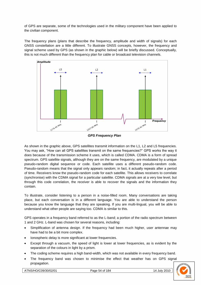
ATNS/HO/C09/30/02/01 Page 54 of 184 14 July 2010
of GPS are separate, some of the technologies used in the military component have been applied to
the civilian component.
The frequency plans (plans that describe the frequency, amplitude and width of signals) for each
GNSS constellation are a little different. To illustrate GNSS concepts, however, the frequency and
signal scheme used by GPS (as shown in the graphic below) will be briefly discussed. Conceptually,
this is not much different than the frequency plan for cable or broadcast television channels.
GPS Frequency Plan
As shown in the graphic above, GPS satellites transmit information on the L1, L2 and L5 frequencies.
You may ask, ―How can all GPS satellites transmit on the same frequencies?‖ GPS works the way it
does because of the transmission scheme it uses, which is called CDMA. CDMA is a form of spread
spectrum. GPS satellite signals, although they are on the same frequency, are modulated by a unique
pseudo-random digital sequence or code. Each satellite uses a different pseudo-random code.
Pseudo-random means that the signal only appears random; in fact, it actually repeats after a period
of time. Receivers know the pseudo-random code for each satellite. This allows receivers to correlate
(synchronise) with the CDMA signal for a particular satellite. CDMA signals are at a very low level, but
through this code correlation, the receiver is able to recover the signals and the information they
contain.
To illustrate, consider listening to a person in a noise-filled room. Many conversations are taking
place, but each conversation is in a different language. You are able to understand the person
because you know the language that they are speaking. If you are multi-lingual, you will be able to
understand what other people are saying too. CDMA is similar to this.
GPS operates in a frequency band referred to as the L-band; a portion of the radio spectrum between
1 and 2 GHz. L-band was chosen for several reasons, including:
Simplification of antenna design. If the frequency had been much higher, user antennae may
have had to be a bit more complex.
Ionospheric delay is more significant at lower frequencies.
Except through a vacuum, the speed of light is lower at lower frequencies, as is evident by the
separation of the colours in light by a prism.
The coding scheme requires a high band-width, which was not available in every frequency band.
The frequency band was chosen to minimise the effect that weather has on GPS signal
propagation.

ATNS/HO/C09/30/02/01 Page 55 of 184 14 July 2010
GPS Navigation Message
The P(Y) code is for military use. It provides better interference rejection than the C/A code, which
makes military GPS more robust than civilian GPS. The L2 frequency transmits the P(Y) code and on
newer GPS satellites, it also transmits the C/A code (referred to as L2C), providing a second publicly
available code for civilian users.
While the GPS transmission scheme is complex, it was chosen for many good reasons:
GPS receivers can recover very weak signals using very small antennae. This keeps the receiver
cost low.
Multi-frequency operation allows for ionospheric compensation, since ionospheric delays vary
with frequency.
The GPS is resistant to jamming and interference.
Security. Signals accessed and used by military applications are not accessible by civilians.
Other global navigation satellites systems are conceptually similar to GPS, but there are slight
differences (will be discussed at a later stage).
Why does time play such an important role in GNSS? It is because the time it takes a GNSS signal to
travel from satellites to receivers is used to determine distances (ranges) to satellites. Accuracy is
required because radio waves travel at the speed of light. In one microsecond (a millionth of a
second), light travels 300 m. In a nanosecond (a billionth of a second), light travels 30 cm. Small
errors in time can therefore result in large errors in position.
How does GNSS positioning actually work? For each satellite being tracked, the receiver calculates
how long the satellite signal took to reach it, as follows:
Propagation time = Time signal reached receiver – Time signal left satellite
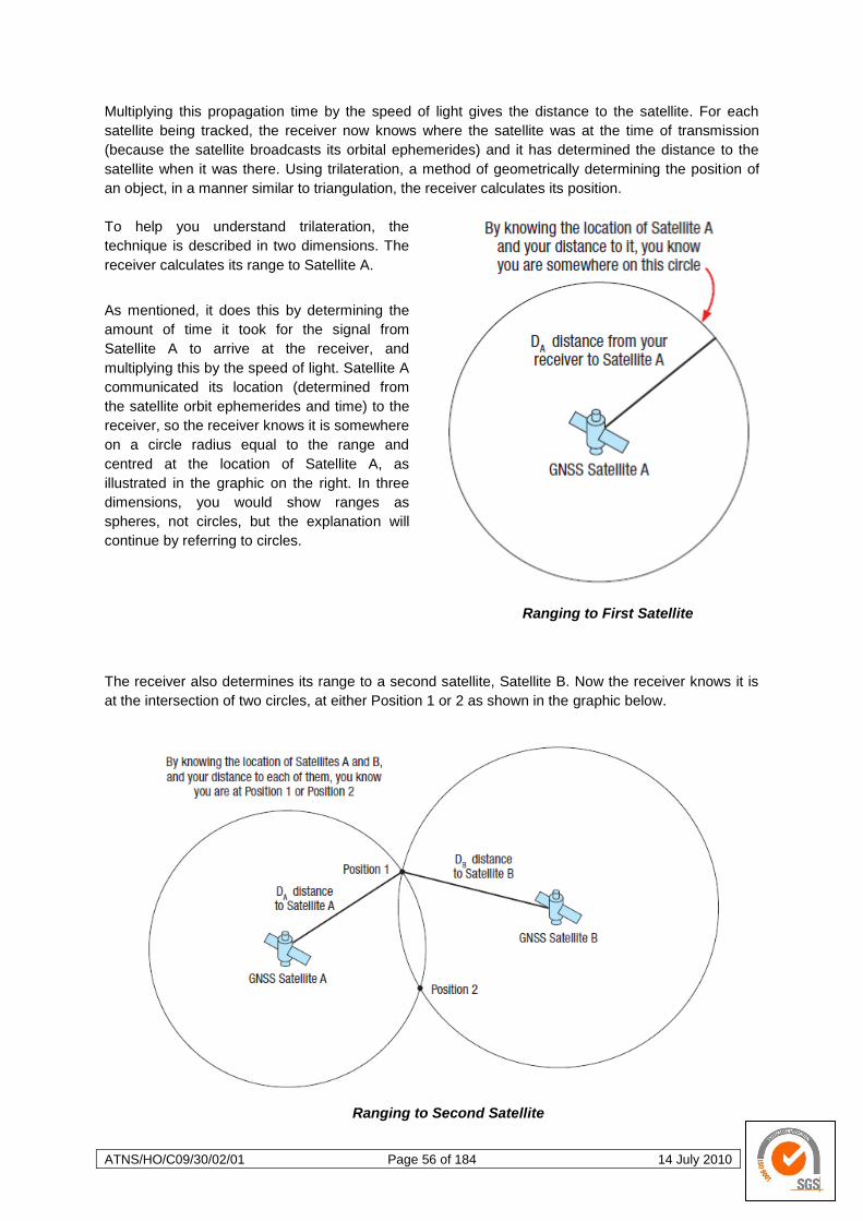
ATNS/HO/C09/30/02/01 Page 56 of 184 14 July 2010
Multiplying this propagation time by the speed of light gives the distance to the satellite. For each
satellite being tracked, the receiver now knows where the satellite was at the time of transmission
(because the satellite broadcasts its orbital ephemerides) and it has determined the distance to the
satellite when it was there. Using trilateration, a method of geometrically determining the position of
an object, in a manner similar to triangulation, the receiver calculates its position.
To help you understand trilateration, the
technique is described in two dimensions. The
receiver calculates its range to Satellite A.
As mentioned, it does this by determining the
amount of time it took for the signal from
Satellite A to arrive at the receiver, and
multiplying this by the speed of light. Satellite A
communicated its location (determined from
the satellite orbit ephemerides and time) to the
receiver, so the receiver knows it is somewhere
on a circle radius equal to the range and
centred at the location of Satellite A, as
illustrated in the graphic on the right. In three
dimensions, you would show ranges as
spheres, not circles, but the explanation will
continue by referring to circles.
Ranging to First Satellite
The receiver also determines its range to a second satellite, Satellite B. Now the receiver knows it is
at the intersection of two circles, at either Position 1 or 2 as shown in the graphic below.
Ranging to Second Satellite
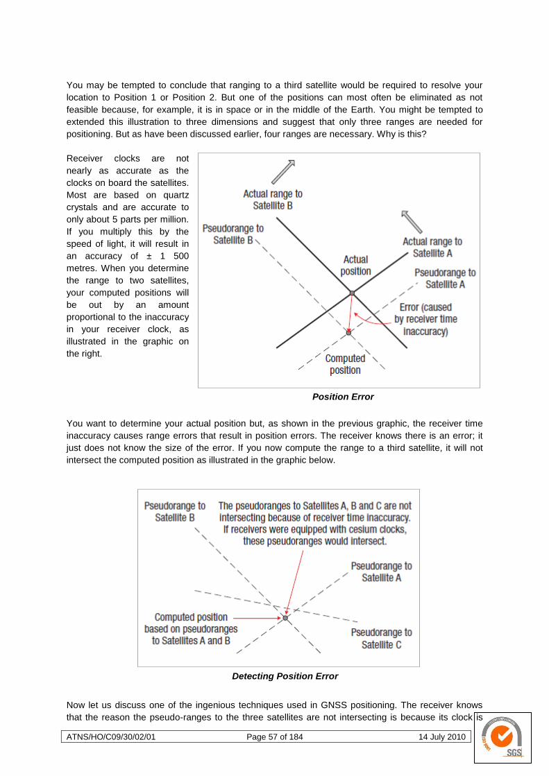
ATNS/HO/C09/30/02/01 Page 57 of 184 14 July 2010
You may be tempted to conclude that ranging to a third satellite would be required to resolve your
location to Position 1 or Position 2. But one of the positions can most often be eliminated as not
feasible because, for example, it is in space or in the middle of the Earth. You might be tempted to
extended this illustration to three dimensions and suggest that only three ranges are needed for
positioning. But as have been discussed earlier, four ranges are necessary. Why is this?
Receiver clocks are not
nearly as accurate as the
clocks on board the satellites.
Most are based on quartz
crystals and are accurate to
only about 5 parts per million.
If you multiply this by the
speed of light, it will result in
an accuracy of ± 1 500
metres. When you determine
the range to two satellites,
your computed positions will
be out by an amount
proportional to the inaccuracy
in your receiver clock, as
illustrated in the graphic on
the right.
Position Error
You want to determine your actual position but, as shown in the previous graphic, the receiver time
inaccuracy causes range errors that result in position errors. The receiver knows there is an error; it
just does not know the size of the error. If you now compute the range to a third satellite, it will not
intersect the computed position as illustrated in the graphic below.
Detecting Position Error
Now let us discuss one of the ingenious techniques used in GNSS positioning. The receiver knows
that the reason the pseudo-ranges to the three satellites are not intersecting is because its clock is
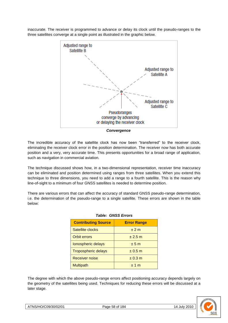
ATNS/HO/C09/30/02/01 Page 58 of 184 14 July 2010
inaccurate. The receiver is programmed to advance or delay its clock until the pseudo-ranges to the
three satellites converge at a single point as illustrated in the graphic below.
Convergence
The incredible accuracy of the satellite clock has now been ―transferred‖ to the receiver clock,
eliminating the receiver clock error in the position determination. The receiver now has both accurate
position and a very, very accurate time. This presents opportunities for a broad range of application,
such as navigation in commercial aviation.
The technique discussed shows how, in a two-dimensional representation, receiver time inaccuracy
can be eliminated and position determined using ranges from three satellites. When you extend this
technique to three dimensions, you need to add a range to a fourth satellite. This is the reason why
line-of-sight to a minimum of four GNSS satellites is needed to determine position.
There are various errors that can affect the accuracy of standard GNSS pseudo-range determination,
i.e. the determination of the pseudo-range to a single satellite. These errors are shown in the table
below:
Table: GNSS Errors
Contributing Source Error Range
Satellite clocks ± 2 m
Orbit errors ± 2.5 m
Ionospheric delays ± 5 m
Tropospheric delays ± 0.5 m
Receiver noise ± 0.3 m
Multipath ± 1 m
The degree with which the above pseudo-range errors affect positioning accuracy depends largely on
the geometry of the satellites being used. Techniques for reducing these errors will be discussed at a
later stage.

ATNS/HO/C09/30/02/01 Page 59 of 184 14 July 2010
Once the receiver has determined its position and time, this information is passed to and used by the
user application, such as a flight management system.
Various GNSS Receivers
2.1.1 Almanac
The almanac consists of coarse orbit and status information for each satellite in the GNSS
constellation, an ionospheric model, and information to relate satellite-derived time to
Coordinated Universal Time (UTC). In order to fully comprehend the role of the almanac it is
necessary to first describe the radio signals (navigation message) sent by a satellite.
GNSS Navigation Message
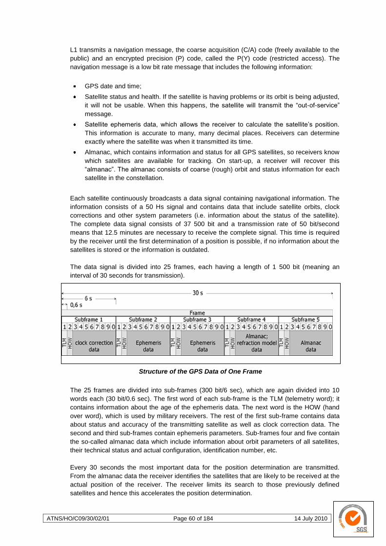
ATNS/HO/C09/30/02/01 Page 60 of 184 14 July 2010
L1 transmits a navigation message, the coarse acquisition (C/A) code (freely available to the
public) and an encrypted precision (P) code, called the P(Y) code (restricted access). The
navigation message is a low bit rate message that includes the following information:
GPS date and time;
Satellite status and health. If the satellite is having problems or its orbit is being adjusted,
it will not be usable. When this happens, the satellite will transmit the ―out-of-service‖
message.
Satellite ephemeris data, which allows the receiver to calculate the satellite‘s position.
This information is accurate to many, many decimal places. Receivers can determine
exactly where the satellite was when it transmitted its time.
Almanac, which contains information and status for all GPS satellites, so receivers know
which satellites are available for tracking. On start-up, a receiver will recover this
―almanac‖. The almanac consists of coarse (rough) orbit and status information for each
satellite in the constellation.
Each satellite continuously broadcasts a data signal containing navigational information. The
information consists of a 50 Hs signal and contains data that include satellite orbits, clock
corrections and other system parameters (i.e. information about the status of the satellite).
The complete data signal consists of 37 500 bit and a transmission rate of 50 bit/second
means that 12.5 minutes are necessary to receive the complete signal. This time is required
by the receiver until the first determination of a position is possible, if no information about the
satellites is stored or the information is outdated.
The data signal is divided into 25 frames, each having a length of 1 500 bit (meaning an
interval of 30 seconds for transmission).
Structure of the GPS Data of One Frame
The 25 frames are divided into sub-frames (300 bit/6 sec), which are again divided into 10
words each (30 bit/0.6 sec). The first word of each sub-frame is the TLM (telemetry word); it
contains information about the age of the ephemeris data. The next word is the HOW (hand
over word), which is used by military receivers. The rest of the first sub-frame contains data
about status and accuracy of the transmitting satellite as well as clock correction data. The
second and third sub-frames contain ephemeris parameters. Sub-frames four and five contain
the so-called almanac data which include information about orbit parameters of all satellites,
their technical status and actual configuration, identification number, etc.
Every 30 seconds the most important data for the position determination are transmitted.
From the almanac data the receiver identifies the satellites that are likely to be received at the
actual position of the receiver. The receiver limits its search to those previously defined
satellites and hence this accelerates the position determination.

ATNS/HO/C09/30/02/01 Page 61 of 184 14 July 2010
As mentioned earlier, the data signal contains a correction parameter for the satellite‘s clocks.
Why is this necessary if the atomic clocks are absolutely precise? Each satellite carries
several atomic clocks and has very accurate time. However, the atomic clocks of the
individual satellites are not synchronised to the GPS reference time, but run independently of
each other (periodic adjustments are made to align the timing of these clocks). Therefore,
correction data for the clocks of each satellite are required. Furthermore, the GPS reference
time is different from the UTC time. UTC is synchronised with the rotation of the Earth by
means of leap seconds.
A typical reason why satellites are marked as defective is the necessity for an orbit correction.
In such a case the satellite is marked as defective, once the satellite is stabilised in its new
orbit, the defective marking is removed.
When ephemeris and almanac data are stored in the receiver, the ―age‖ of the data will
influence how long the receiver needs to calculate the first position determination. If the
receiver has not had any contact with the satellites for an extended period of time, the first
position determination will take longer. If the contact has only been interrupted for a short time
(e.g. the aircraft was on the hardstand for a quick turn-around), the position determination is
restarted instantly. Establishing GNSS position calculation using visible satellites with good
geometry is known as reacquisition (or reacquire).
If position and time are known and the almanac and ephemeris data are up-to-date, the
system is able to reacquire the satellites almost instantaneously; this is referred to as a hot
start. This is the case when the receiver is turned on at approximately the same position
where it was turned off and within 2 – 6 hours after the last position determination. In this
case a position fix can be obtained within approximately 15 seconds (this may happen during
a quick turn-around or a short stop).
If the almanac data are available and the time of the receiver is correct but the ephemeris
data are outdated, the reacquisition will take a bit longer and this is referred to as a warm
start. In this case it takes about 45 seconds to actualise the ephemeris data and obtain a
position fix. Ephemeris data are outdated when more than 2 – 6 hours have elapsed since the
last data reception from the satellites in view. The more new satellites have come into view
since the last position determination, the longer the warm start takes.
If neither ephemeris nor almanac data and the last position are known, the acquisition
process is started with no known information; this is referred to as a cold start. The first step
then is that all the almanac data have to be collected from the satellites; this procedure takes
up to 12.5 minutes. This happens when the receiver was switched off for several hours, was
stored without batteries or was moved approximately 300 km or more since the last position
fix.
In the last case no almanac data have to be collected, but as the ―wrong‖ satellites are in
view, the receiver has to screen all the satellite data until it finds the information for the
satellites that are in view. For many receivers, the duration of a cold start can be shortened
when the date and approximate position are entered manually.
2.1.2 GNSS Segments
The GNSS consists of three major components or ―segments‖: the space segment, the
control segment and the user segment. These are illustrated in the graphic below.
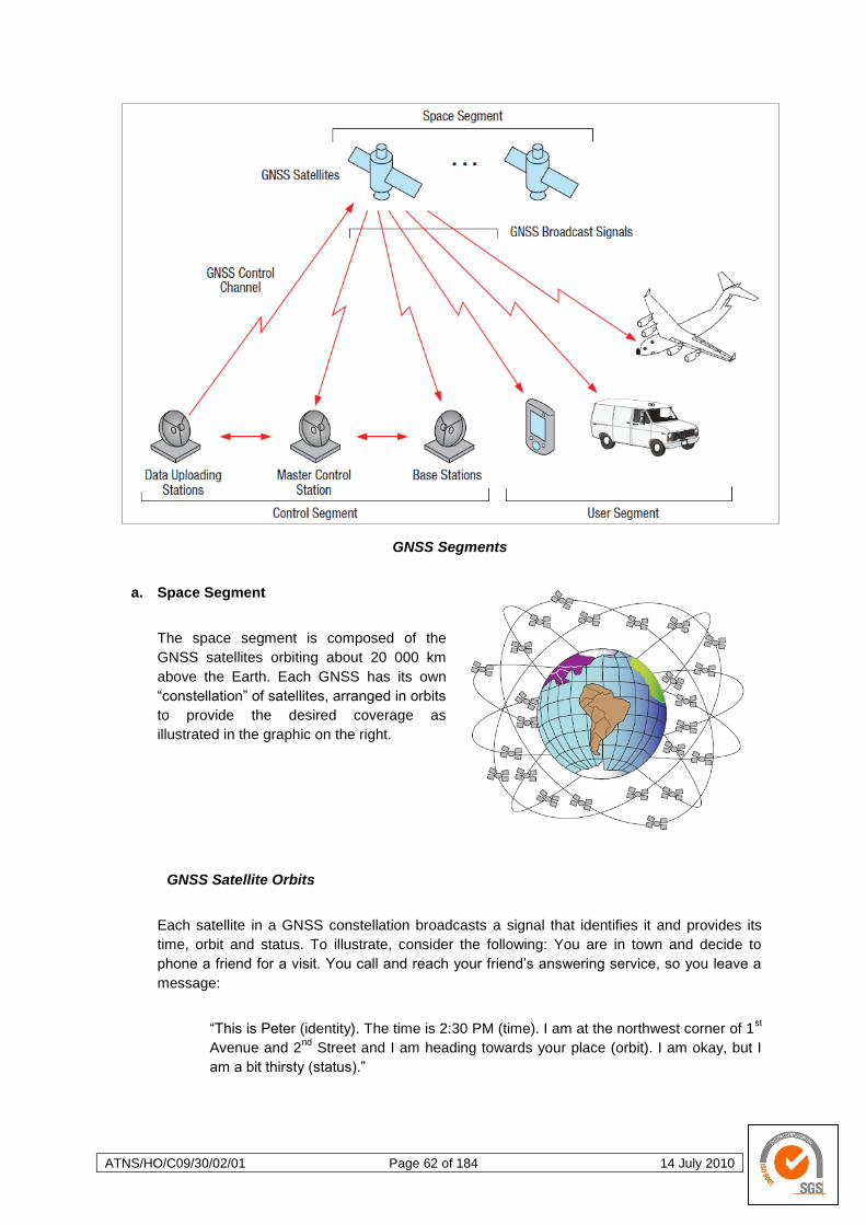
ATNS/HO/C09/30/02/01 Page 62 of 184 14 July 2010
GNSS Segments
a. Space Segment
The space segment is composed of the
GNSS satellites orbiting about 20 000 km
above the Earth. Each GNSS has its own
―constellation‖ of satellites, arranged in orbits
to provide the desired coverage as
illustrated in the graphic on the right.
GNSS Satellite Orbits
Each satellite in a GNSS constellation broadcasts a signal that identifies it and provides its
time, orbit and status. To illustrate, consider the following: You are in town and decide to
phone a friend for a visit. You call and reach your friend‘s answering service, so you leave a
message:
―This is Peter (identity). The time is 2:30 PM (time). I am at the northwest corner of 1st
Avenue and 2nd
Street and I am heading towards your place (orbit). I am okay, but I
am a bit thirsty (status).‖
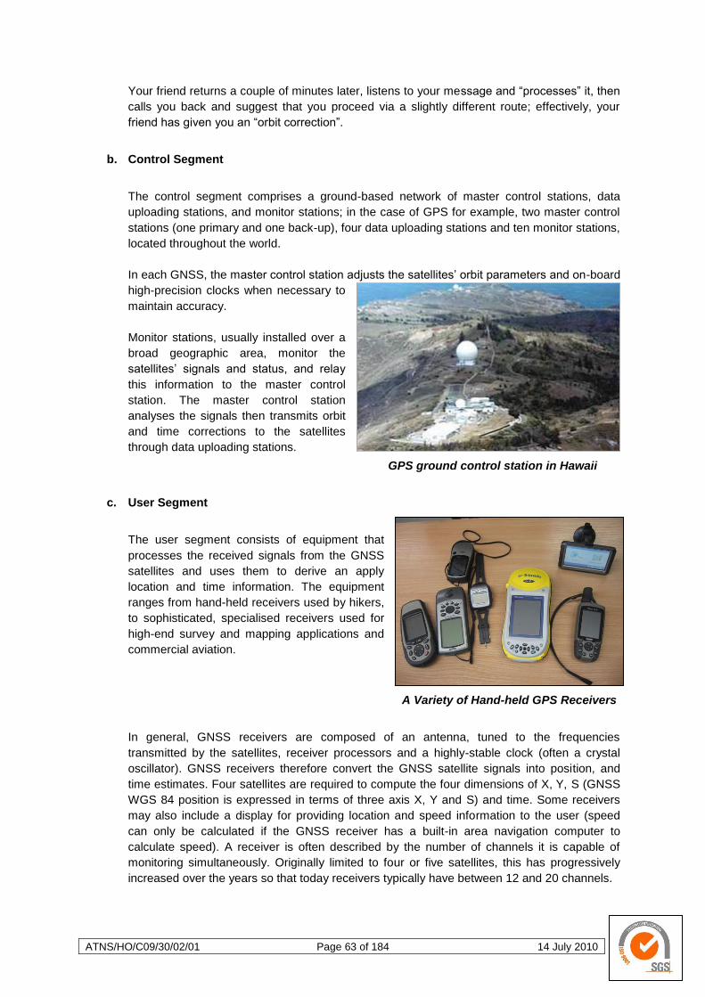
ATNS/HO/C09/30/02/01 Page 63 of 184 14 July 2010
Your friend returns a couple of minutes later, listens to your message and ―processes‖ it, then
calls you back and suggest that you proceed via a slightly different route; effectively, your
friend has given you an ―orbit correction‖.
b. Control Segment
The control segment comprises a ground-based network of master control stations, data
uploading stations, and monitor stations; in the case of GPS for example, two master control
stations (one primary and one back-up), four data uploading stations and ten monitor stations,
located throughout the world.
In each GNSS, the master control station adjusts the satellites‘ orbit parameters and on-board
high-precision clocks when necessary to
maintain accuracy.
Monitor stations, usually installed over a
broad geographic area, monitor the
satellites‘ signals and status, and relay
this information to the master control
station. The master control station
analyses the signals then transmits orbit
and time corrections to the satellites
through data uploading stations.
GPS ground control station in Hawaii
c. User Segment
The user segment consists of equipment that
processes the received signals from the GNSS
satellites and uses them to derive an apply
location and time information. The equipment
ranges from hand-held receivers used by hikers,
to sophisticated, specialised receivers used for
high-end survey and mapping applications and
commercial aviation.
A Variety of Hand-held GPS Receivers
In general, GNSS receivers are composed of an antenna, tuned to the frequencies
transmitted by the satellites, receiver processors and a highly-stable clock (often a crystal
oscillator). GNSS receivers therefore convert the GNSS satellite signals into position, and
time estimates. Four satellites are required to compute the four dimensions of X, Y, S (GNSS
WGS 84 position is expressed in terms of three axis X, Y and S) and time. Some receivers
may also include a display for providing location and speed information to the user (speed
can only be calculated if the GNSS receiver has a built-in area navigation computer to
calculate speed). A receiver is often described by the number of channels it is capable of
monitoring simultaneously. Originally limited to four or five satellites, this has progressively
increased over the years so that today receivers typically have between 12 and 20 channels.
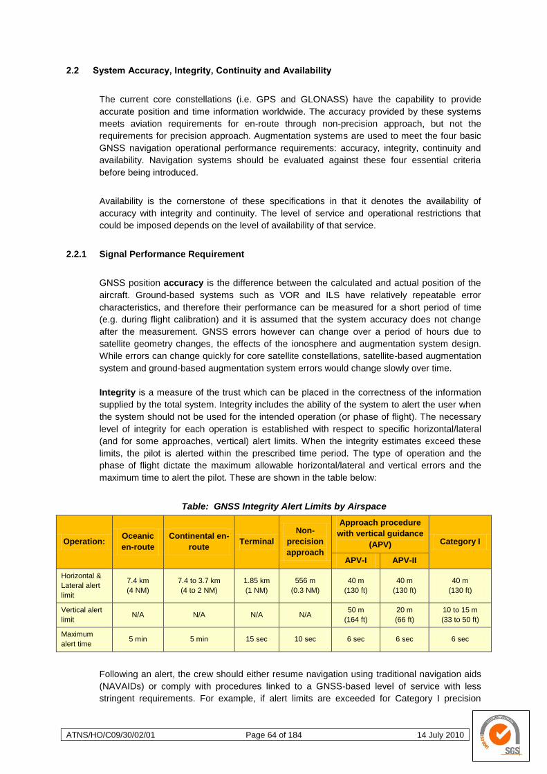
ATNS/HO/C09/30/02/01 Page 64 of 184 14 July 2010
2.2 System Accuracy, Integrity, Continuity and Availability
The current core constellations (i.e. GPS and GLONASS) have the capability to provide
accurate position and time information worldwide. The accuracy provided by these systems
meets aviation requirements for en-route through non-precision approach, but not the
requirements for precision approach. Augmentation systems are used to meet the four basic
GNSS navigation operational performance requirements: accuracy, integrity, continuity and
availability. Navigation systems should be evaluated against these four essential criteria
before being introduced.
Availability is the cornerstone of these specifications in that it denotes the availability of
accuracy with integrity and continuity. The level of service and operational restrictions that
could be imposed depends on the level of availability of that service.
2.2.1 Signal Performance Requirement
GNSS position accuracy is the difference between the calculated and actual position of the
aircraft. Ground-based systems such as VOR and ILS have relatively repeatable error
characteristics, and therefore their performance can be measured for a short period of time
(e.g. during flight calibration) and it is assumed that the system accuracy does not change
after the measurement. GNSS errors however can change over a period of hours due to
satellite geometry changes, the effects of the ionosphere and augmentation system design.
While errors can change quickly for core satellite constellations, satellite-based augmentation
system and ground-based augmentation system errors would change slowly over time.
Integrity is a measure of the trust which can be placed in the correctness of the information
supplied by the total system. Integrity includes the ability of the system to alert the user when
the system should not be used for the intended operation (or phase of flight). The necessary
level of integrity for each operation is established with respect to specific horizontal/lateral
(and for some approaches, vertical) alert limits. When the integrity estimates exceed these
limits, the pilot is alerted within the prescribed time period. The type of operation and the
phase of flight dictate the maximum allowable horizontal/lateral and vertical errors and the
maximum time to alert the pilot. These are shown in the table below:
Table: GNSS Integrity Alert Limits by Airspace
Operation: Oceanic
en-route
Continental en-
route Terminal
Non-
precision
approach
Approach procedure
with vertical guidance
(APV) Category I
APV-I APV-II
Horizontal &
Lateral alert
limit
7.4 km
(4 NM)
7.4 to 3.7 km
(4 to 2 NM)
1.85 km
(1 NM)
556 m
(0.3 NM)
40 m
(130 ft)
40 m
(130 ft)
40 m
(130 ft)
Vertical alert
limit N/A N/A N/A N/A
50 m
(164 ft)
20 m
(66 ft)
10 to 15 m
(33 to 50 ft)
Maximum
alert time 5 min 5 min 15 sec 10 sec 6 sec 6 sec 6 sec
Following an alert, the crew should either resume navigation using traditional navigation aids
(NAVAIDs) or comply with procedures linked to a GNSS-based level of service with less
stringent requirements. For example, if alert limits are exceeded for Category I precision

ATNS/HO/C09/30/02/01 Page 65 of 184 14 July 2010
approach, before the aircraft crosses the final approach fix, the crew could restrict descend to
a decision altitude associated with APV operation.
Continuity is the capability of the system to perform its function without unscheduled
interruptions during the intended operation. This is expressed as a probability. For example,
there should be a high probability that the service remains available throughout a full
instrument approach procedure. Continuity requirements vary from a lower value for low
traffic density en-route airspace to a higher value for areas with high traffic density and
airspace complexity, where a failure could affect a large number of aircraft. Where there is a
high degree of reliance on the system for navigation, mitigation against failure may be
achieved through the use of alternative (most often conventional) navigation means or
through the use of air traffic control surveillance (most often radar monitoring) and
intervention to ensure that separation is maintained.
For approach and landing operations, each aircraft can be considered individually. The results
of a disruption of service would normally relate only to the risks associated with a missed
approach. For non-precision, APV and Category I approaches, missed approach is
considered a normal operation, since it occurs whenever the aircraft descends to the
minimum altitude for the approach and the pilot is unable to continue with visual reference.
This is therefore an operational efficiency issue, not a safety issue.
The availability of a service is the portion of time during which the system is simultaneously
delivering the required accuracy, integrity and continuity. The availability of GNSS is
complicated by the movement of satellites relative to a coverage area and by the potentially
long time it takes to restore a satellite in the event of a failure. The level of availability for a
certain airspace at a certain time should be determined through design, analysis and
modelling, rather than through measurement. The availability specifications (i.e. signal-in-
space performance requirements) in the table below, present a range of values valid for all
phases of flight. When establishing the availability requirements for GNSS, the desired level
of service to be supported is considered. Availability should be directly proportional to the
reliance on a GNSS element used in support of a particular phase of flight.
Table: Signal-in-space Performance Requirements
Typical
Operation
Accuracy
Horizontal
95%
(Notes 1 and 3)
Accuracy
Vertical
95%
(Notes 1 and 3)
Integrity
(Note 2)
Time-to-
alert
(Note 3)
Continuity
(Note 4)
Availability
(Note 5)
En-route 3.7 km
(2.0 NM)
N/A 1 – 1 x 10⁻⁷/h 5 min 1 – 1 x 10
-4/h
to 1 – 1 x 10⁻⁸/h
0.99 to
0.99999
En-route,
Terminal
0.74 km
(0.4 NM)
N/A 1 – 1 x 10⁻⁷/h 15 sec 1 – 1 x 10
-4/h
to 1 – 1 x 10⁻⁸/h
0.99 to
0.99999
Initial approach,
Intermediate
approach,
Non-precision
approach (NPA),
Departure
220 m
(720 ft)
N/A 1 – 1 x 10⁻⁷/h 10 sec 1 – 1 x 10
-4/h
to 1 – 1 x 10⁻⁸/h
0.99 to
0.99999
Approach
operations with
vertical guidance
(APV-I)
16.0 m
(52 ft)
20 m
(66 ft)
1 – 2 x 10⁻⁷/h
in any
approach
10 sec 1 – 8 x 10⁻⁶/h per
15 sec
0.99 to
0.99999
Approach
operations with
vertical guidance
(APV-II)
16.0 m
(52 ft)
8 m
(26 ft)
1 – 2 x 10⁻⁷/h
in any
approach
6 sec 1 – 8 x 10⁻⁶/h per
15 sec
0.99 to
0.99999
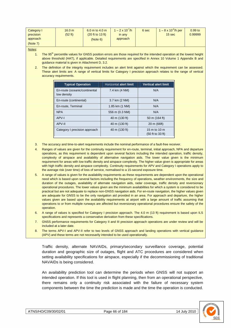
ATNS/HO/C09/30/02/01 Page 66 of 184 14 July 2010
Category I
precision
approach
(Note 7)
16.0 m
(52 ft)
6.0 m to 4.0 m
(20 ft to 13 ft)
(Note 6)
1 – 2 x 10⁻⁷/h
in any
approach
6 sec 1 – 8 x 10⁻⁶/h per
15 sec
0.99 to
0.99999
Notes:
1. The 95th percentile values for GNSS position errors are those required for the intended operation at the lowest height
above threshold (HAT), if applicable. Detailed requirements are specified in Annex 10 Volume 1 Appendix B and
guidance material is given in Attachment D, 3.2.
2. The definition of the integrity requirement includes an alert limit against which the requirement can be assessed.
These alert limits are: A range of vertical limits for Category I precision approach relates to the range of vertical
accuracy requirements.
3. The accuracy and time-to-alert requirements include the nominal performance of a fault-free receiver.
4. Ranges of values are given for the continuity requirement for en-route, terminal, initial approach, NPA and departure
operations, as this requirement is dependent upon several factors including the intended operation, traffic density,
complexity of airspace and availability of alternative navigation aids. The lower value given is the minimum
requirement for areas with low traffic density and airspace complexity. The higher value given is appropriate for areas
with high traffic density and airspace complexity. Continuity requirements for APV and Category I operations apply to
the average risk (over time) of loss of service, normalised to a 15-second exposure time.
5. A range of values is given for the availability requirements as these requirements are dependent upon the operational
need which is based upon several factors including the frequency of operations, weather environments, the size and
duration of the outages, availability of alternate navigation aids, radar coverage, traffic density and reversionary
operational procedures. The lower values given are the minimum availabilities for which a system is considered to be
practical but are not adequate to replace non-GNSS navigation aids. For en-route navigation, the higher values given
are adequate for GNSS to be the only navigation aid provided in an area. For approach and departure, the higher
values given are based upon the availability requirements at airport with a large amount of traffic assuming that
operations to or from multiple runways are affected but reversionary operational procedures ensure the safety of the
operation.
6. A range of values is specified for Category I precision approach. The 4.0 m (13 ft) requirement is based upon ILS
specifications and represents a conservative derivation from these specifications.
7. GNSS performance requirements for Category II and III precision approach operations are under review and will be
included at a later date.
8. The terms APV-I and APV-II refer to two levels of GNSS approach and landing operations with vertical guidance
(APV) and these terms are not necessarily intended to be used operationally.
Traffic density, alternate NAVAIDs, primary/secondary surveillance coverage, potential
duration and geographic size of outages, flight and ATC procedures are considered when
setting availability specifications for airspace, especially if the decommissioning of traditional
NAVAIDs is being considered.
An availability prediction tool can determine the periods when GNSS will not support an
intended operation. If this tool is used in flight planning, then from an operational perspective,
there remains only a continuity risk associated with the failure of necessary system
components between the time the prediction is made and the time the operation is conducted.
Typical Operation Horizontal alert limit Vertical alert limit
En-route (oceanic/continental
low density
7.4 km (4 NM) N/A
En-route (continental) 3.7 km (2 NM) N/A
En-route, Terminal 1.85 km (1 NM) N/A
NPA 556 m (0.3 NM) N/A
APV-I 40 m (130 ft) 50 m (164 ft)
APV-II 40 m (130 ft) 20 m (66ft)
Category I precision approach 40 m (130 ft) 15 m to 10 m
(50 ft to 33 ft)
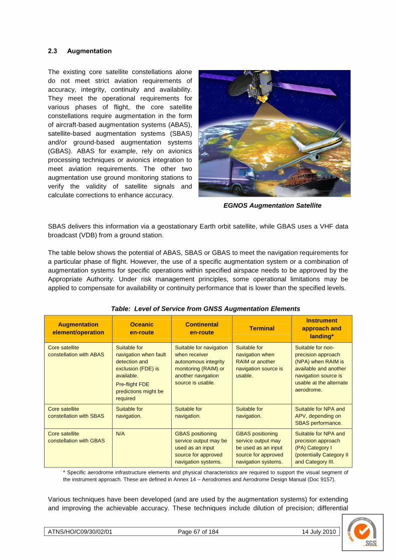
ATNS/HO/C09/30/02/01 Page 67 of 184 14 July 2010
2.3 Augmentation
The existing core satellite constellations alone
do not meet strict aviation requirements of
accuracy, integrity, continuity and availability.
They meet the operational requirements for
various phases of flight, the core satellite
constellations require augmentation in the form
of aircraft-based augmentation systems (ABAS),
satellite-based augmentation systems (SBAS)
and/or ground-based augmentation systems
(GBAS). ABAS for example, rely on avionics
processing techniques or avionics integration to
meet aviation requirements. The other two
augmentation use ground monitoring stations to
verify the validity of satellite signals and
calculate corrections to enhance accuracy.
EGNOS Augmentation Satellite
SBAS delivers this information via a geostationary Earth orbit satellite, while GBAS uses a VHF data
broadcast (VDB) from a ground station.
The table below shows the potential of ABAS, SBAS or GBAS to meet the navigation requirements for
a particular phase of flight. However, the use of a specific augmentation system or a combination of
augmentation systems for specific operations within specified airspace needs to be approved by the
Appropriate Authority. Under risk management principles, some operational limitations may be
applied to compensate for availability or continuity performance that is lower than the specified levels.
Table: Level of Service from GNSS Augmentation Elements
Augmentation
element/operation
Oceanic
en-route
Continental
en-route Terminal
Instrument
approach and
landing*
Core satellite
constellation with ABAS
Suitable for
navigation when fault
detection and
exclusion (FDE) is
available.
Pre-flight FDE
predictions might be
required
Suitable for navigation
when receiver
autonomous integrity
monitoring (RAIM) or
another navigation
source is usable.
Suitable for
navigation when
RAIM or another
navigation source is
usable.
Suitable for non-
precision approach
(NPA) when RAIM is
available and another
navigation source is
usable at the alternate
aerodrome.
Core satellite
constellation with SBAS
Suitable for
navigation.
Suitable for
navigation.
Suitable for
navigation.
Suitable for NPA and
APV, depending on
SBAS performance.
Core satellite
constellation with GBAS
N/A GBAS positioning
service output may be
used as an input
source for approved
navigation systems.
GBAS positioning
service output may
be used as an input
source for approved
navigation systems.
Suitable for NPA and
precision approach
(PA) Category I
(potentially Category II
and Category III.
* Specific aerodrome infrastructure elements and physical characteristics are required to support the visual segment of
the instrument approach. These are defined in Annex 14 – Aerodromes and Aerodrome Design Manual (Doc 9157).
Various techniques have been developed (and are used by the augmentation systems) for extending
and improving the achievable accuracy. These techniques include dilution of precision; differential
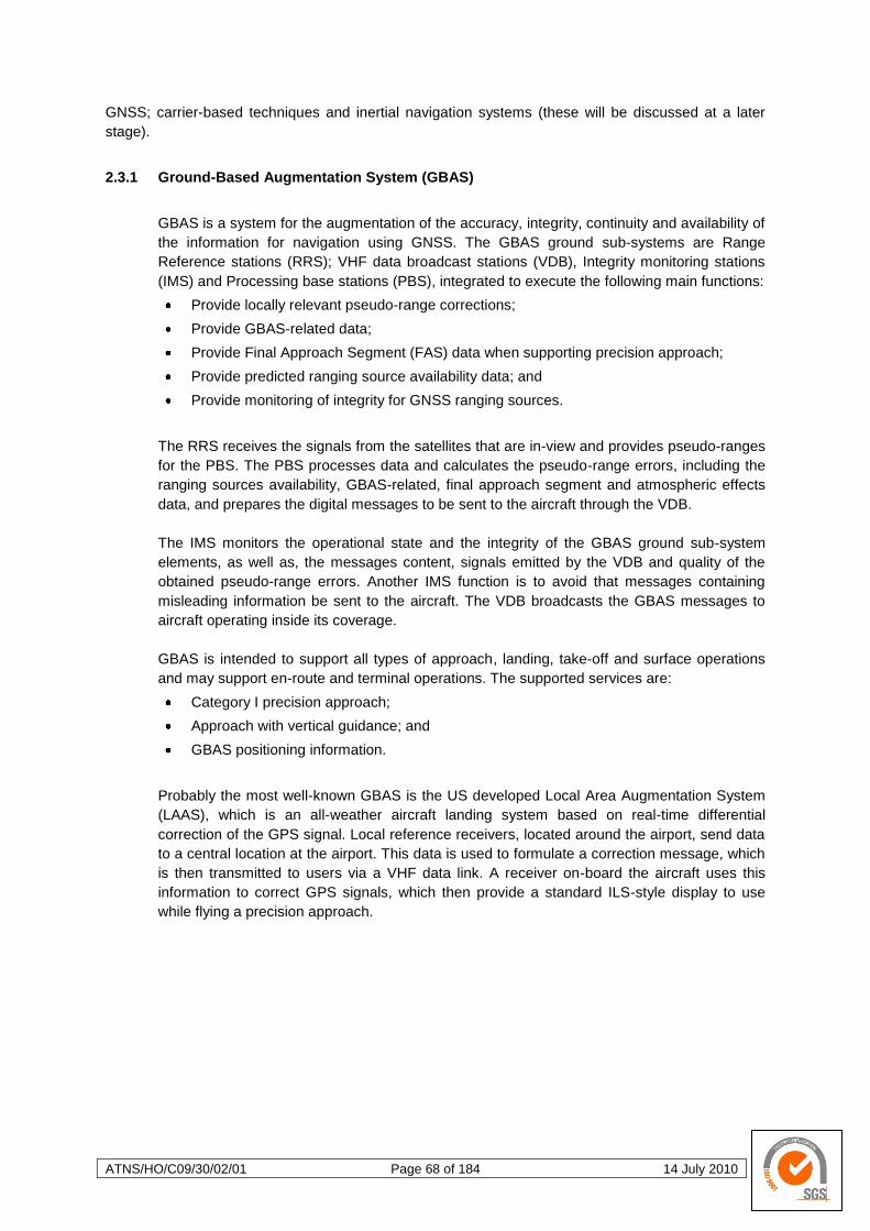
ATNS/HO/C09/30/02/01 Page 68 of 184 14 July 2010
GNSS; carrier-based techniques and inertial navigation systems (these will be discussed at a later
stage).
2.3.1 Ground-Based Augmentation System (GBAS)
GBAS is a system for the augmentation of the accuracy, integrity, continuity and availability of
the information for navigation using GNSS. The GBAS ground sub-systems are Range
Reference stations (RRS); VHF data broadcast stations (VDB), Integrity monitoring stations
(IMS) and Processing base stations (PBS), integrated to execute the following main functions:
Provide locally relevant pseudo-range corrections;
Provide GBAS-related data;
Provide Final Approach Segment (FAS) data when supporting precision approach;
Provide predicted ranging source availability data; and
Provide monitoring of integrity for GNSS ranging sources.
The RRS receives the signals from the satellites that are in-view and provides pseudo-ranges
for the PBS. The PBS processes data and calculates the pseudo-range errors, including the
ranging sources availability, GBAS-related, final approach segment and atmospheric effects
data, and prepares the digital messages to be sent to the aircraft through the VDB.
The IMS monitors the operational state and the integrity of the GBAS ground sub-system
elements, as well as, the messages content, signals emitted by the VDB and quality of the
obtained pseudo-range errors. Another IMS function is to avoid that messages containing
misleading information be sent to the aircraft. The VDB broadcasts the GBAS messages to
aircraft operating inside its coverage.
GBAS is intended to support all types of approach, landing, take-off and surface operations
and may support en-route and terminal operations. The supported services are:
Category I precision approach;
Approach with vertical guidance; and
GBAS positioning information.
Probably the most well-known GBAS is the US developed Local Area Augmentation System
(LAAS), which is an all-weather aircraft landing system based on real-time differential
correction of the GPS signal. Local reference receivers, located around the airport, send data
to a central location at the airport. This data is used to formulate a correction message, which
is then transmitted to users via a VHF data link. A receiver on-board the aircraft uses this
information to correct GPS signals, which then provide a standard ILS-style display to use
while flying a precision approach.
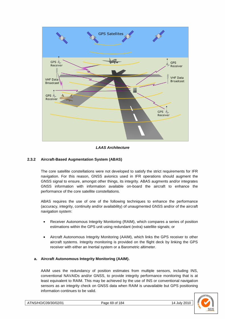
ATNS/HO/C09/30/02/01 Page 69 of 184 14 July 2010
LAAS Architecture
2.3.2 Aircraft-Based Augmentation System (ABAS)
The core satellite constellations were not developed to satisfy the strict requirements for IFR
navigation. For this reason, GNSS avionics used in IFR operations should augment the
GNSS signal to ensure, amongst other things, its integrity. ABAS augments and/or integrates
GNSS information with information available on-board the aircraft to enhance the
performance of the core satellite constellations.
ABAS requires the use of one of the following techniques to enhance the performance
(accuracy, integrity, continuity and/or availability) of unaugmented GNSS and/or of the aircraft
navigation system:
Receiver Autonomous Integrity Monitoring (RAIM), which compares a series of position
estimations within the GPS unit using redundant (extra) satellite signals; or
Aircraft Autonomous Integrity Monitoring (AAIM), which links the GPS receiver to other
aircraft systems. Integrity monitoring is provided on the flight deck by linking the GPS
receiver with either an Inertial system or a Barometric altimeter.
a. Aircraft Autonomous Integrity Monitoring (AAIM).
AAIM uses the redundancy of position estimates from multiple sensors, including INS,
conventional NAVAIDs and/or GNSS, to provide integrity performance monitoring that is at
least equivalent to RAIM. This may be achieved by the use of INS or conventional navigation
sensors as an integrity check on GNSS data when RAIM is unavailable but GPS positioning
information continues to be valid.
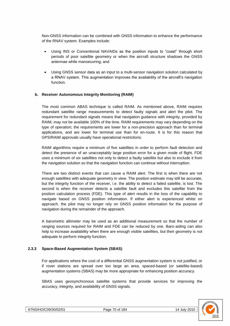
ATNS/HO/C09/30/02/01 Page 70 of 184 14 July 2010
Non-GNSS information can be combined with GNSS information to enhance the performance
of the RNAV system. Examples include:
Using INS or Conventional NAVAIDs as the position inputs to ―coast‖ through short
periods of poor satellite geometry or when the aircraft structure shadows the GNSS
antennae while manoeuvring; and
Using GNSS sensor data as an input to a multi-sensor navigation solution calculated by
a RNAV system. This augmentation improves the availability of the aircraft‘s navigation
function.
b. Receiver Autonomous Integrity Monitoring (RAIM)
The most common ABAS technique is called RAIM. As mentioned above, RAIM requires
redundant satellite range measurements to detect faulty signals and alert the pilot. The
requirement for redundant signals means that navigation guidance with integrity, provided by
RAIM, may not be available 100% of the time. RAIM requirements may vary depending on the
type of operation; the requirements are lower for a non-precision approach than for terminal
applications, and are lower for terminal use than for en-route. It is for this reason that
GPS/RAIM approvals usually have operational restrictions.
RAIM algorithms require a minimum of five satellites in order to perform fault detection and
detect the presence of an unacceptably large position error for a given mode of flight. FDE
uses a minimum of six satellites not only to detect a faulty satellite but also to exclude it from
the navigation solution so that the navigation function can continue without interruption.
There are two distinct events that can cause a RAIM alert. The first is when there are not
enough satellites with adequate geometry in view. The position estimate may still be accurate,
but the integrity function of the receiver, i.e. the ability to detect a failed satellite, is lost. The
second is when the receiver detects a satellite fault and excludes this satellite from the
position calculation process (FDE). This type of alert results in the loss of the capability to
navigate based on GNSS position information. If either alert is experienced whilst on
approach, the pilot may no longer rely on GNSS position information for the purpose of
navigation during the remainder of the approach.
A barometric altimeter may be used as an additional measurement so that the number of
ranging sources required for RAIM and FDE can be reduced by one. Baro-aiding can also
help to increase availability when there are enough visible satellites, but their geometry is not
adequate to perform integrity function.
2.3.3 Space-Based Augmentation System (SBAS)
For applications where the cost of a differential GNSS augmentation system is not justified, or
if rover stations are spread over too large an area, spaced-based (or satellite-based)
augmentation systems (SBAS) may be more appropriate for enhancing position accuracy.
SBAS uses geosynchronous satellite systems that provide services for improving the
accuracy, integrity, and availability of GNSS signals.
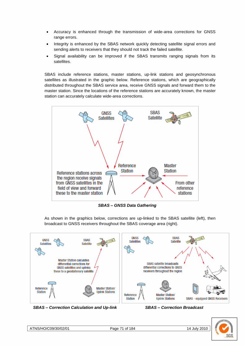
ATNS/HO/C09/30/02/01 Page 71 of 184 14 July 2010
Accuracy is enhanced through the transmission of wide-area corrections for GNSS
range errors.
Integrity is enhanced by the SBAS network quickly detecting satellite signal errors and
sending alerts to receivers that they should not track the failed satellite.
Signal availability can be improved if the SBAS transmits ranging signals from its
satellites.
SBAS include reference stations, master stations, up-link stations and geosynchronous
satellites as illustrated in the graphic below. Reference stations, which are geographically
distributed throughout the SBAS service area, receive GNSS signals and forward them to the
master station. Since the locations of the reference stations are accurately known, the master
station can accurately calculate wide-area corrections.
SBAS – GNSS Data Gathering
As shown in the graphics below, corrections are up-linked to the SBAS satellite (left), then
broadcast to GNSS receivers throughout the SBAS coverage area (right).
SBAS – Correction Calculation and Up-link SBAS – Correction Broadcast
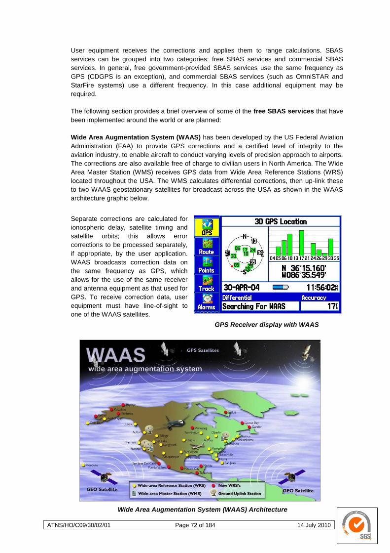
ATNS/HO/C09/30/02/01 Page 72 of 184 14 July 2010
User equipment receives the corrections and applies them to range calculations. SBAS
services can be grouped into two categories: free SBAS services and commercial SBAS
services. In general, free government-provided SBAS services use the same frequency as
GPS (CDGPS is an exception), and commercial SBAS services (such as OmniSTAR and
StarFire systems) use a different frequency. In this case additional equipment may be
required.
The following section provides a brief overview of some of the free SBAS services that have
been implemented around the world or are planned:
Wide Area Augmentation System (WAAS) has been developed by the US Federal Aviation
Administration (FAA) to provide GPS corrections and a certified level of integrity to the
aviation industry, to enable aircraft to conduct varying levels of precision approach to airports.
The corrections are also available free of charge to civilian users in North America. The Wide
Area Master Station (WMS) receives GPS data from Wide Area Reference Stations (WRS)
located throughout the USA. The WMS calculates differential corrections, then up-link these
to two WAAS geostationary satellites for broadcast across the USA as shown in the WAAS
architecture graphic below.
Separate corrections are calculated for
ionospheric delay, satellite timing and
satellite orbits; this allows error
corrections to be processed separately,
if appropriate, by the user application.
WAAS broadcasts correction data on
the same frequency as GPS, which
allows for the use of the same receiver
and antenna equipment as that used for
GPS. To receive correction data, user
equipment must have line-of-sight to
one of the WAAS satellites.
GPS Receiver display with WAAS
Wide Area Augmentation System (WAAS) Architecture
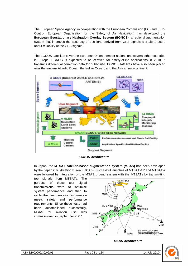
ATNS/HO/C09/30/02/01 Page 73 of 184 14 July 2010
The European Space Agency, in co-operation with the European Commission (EC) and Euro-
Control (European Organisation for the Safety of Air Navigation) has developed the
European Geostationary Navigation Overlay System (EGNOS), a regional augmentation
system that improves the accuracy of positions derived from GPS signals and alerts users
about reliability of the GPS signals.
The EGNOS satellites cover the European Union member nations and several other countries
in Europe. EGNOS is expected to be certified for safety-of-life applications in 2010. It
transmits differential correction data for public use. EGNOS satellites have also been placed
over the eastern Atlantic Ocean, the Indian Ocean, and the African mid-continent.
EGNOS Architecture
In Japan, the MTSAT satellite-based augmentation system (MSAS) has been developed
by the Japan Civil Aviation Bureau (JCAB). Successful launches of MTSAT-1R and MTSAT-2
were followed by integration of the MSAS ground system with the MTSATs by transmitting
test signals from MTSATs. The
purpose of these test signal
transmissions were to optimise
system performance and then to
verify that augmentation information
meets safety and performance
requirements. Since those tests had
been accomplished successfully,
MSAS for aviation use was
commissioned in September 2007.
MSAS Architecture
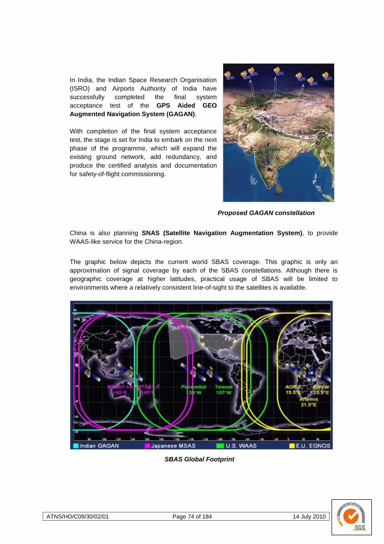
ATNS/HO/C09/30/02/01 Page 74 of 184 14 July 2010
In India, the Indian Space Research Organisation
(ISRO) and Airports Authority of India have
successfully completed the final system
acceptance test of the GPS Aided GEO
Augmented Navigation System (GAGAN).
With completion of the final system acceptance
test, the stage is set for India to embark on the next
phase of the programme, which will expand the
existing ground network, add redundancy, and
produce the certified analysis and documentation
for safety-of-flight commissioning.
Proposed GAGAN constellation
China is also planning SNAS (Satellite Navigation Augmentation System), to provide
WAAS-like service for the China-region.
The graphic below depicts the current world SBAS coverage. This graphic is only an
approximation of signal coverage by each of the SBAS constellations. Although there is
geographic coverage at higher latitudes, practical usage of SBAS will be limited to
environments where a relatively consistent line-of-sight to the satellites is available.
SBAS Global Footprint
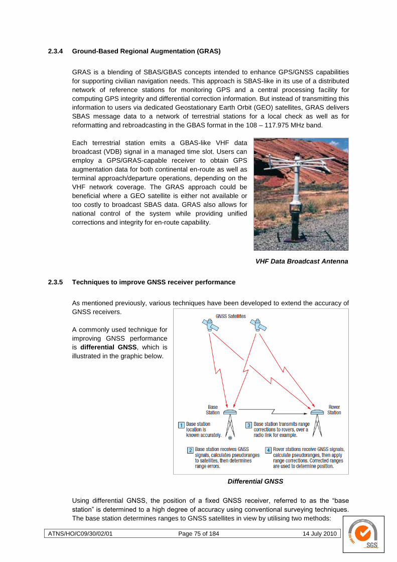
ATNS/HO/C09/30/02/01 Page 75 of 184 14 July 2010
2.3.4 Ground-Based Regional Augmentation (GRAS)
GRAS is a blending of SBAS/GBAS concepts intended to enhance GPS/GNSS capabilities
for supporting civilian navigation needs. This approach is SBAS-like in its use of a distributed
network of reference stations for monitoring GPS and a central processing facility for
computing GPS integrity and differential correction information. But instead of transmitting this
information to users via dedicated Geostationary Earth Orbit (GEO) satellites, GRAS delivers
SBAS message data to a network of terrestrial stations for a local check as well as for
reformatting and rebroadcasting in the GBAS format in the 108 – 117.975 MHz band.
Each terrestrial station emits a GBAS-like VHF data
broadcast (VDB) signal in a managed time slot. Users can
employ a GPS/GRAS-capable receiver to obtain GPS
augmentation data for both continental en-route as well as
terminal approach/departure operations, depending on the
VHF network coverage. The GRAS approach could be
beneficial where a GEO satellite is either not available or
too costly to broadcast SBAS data. GRAS also allows for
national control of the system while providing unified
corrections and integrity for en-route capability.
VHF Data Broadcast Antenna
2.3.5 Techniques to improve GNSS receiver performance
As mentioned previously, various techniques have been developed to extend the accuracy of
GNSS receivers.
A commonly used technique for
improving GNSS performance
is differential GNSS, which is
illustrated in the graphic below.
Differential GNSS
Using differential GNSS, the position of a fixed GNSS receiver, referred to as the ―base
station‖ is determined to a high degree of accuracy using conventional surveying techniques.
The base station determines ranges to GNSS satellites in view by utilising two methods:
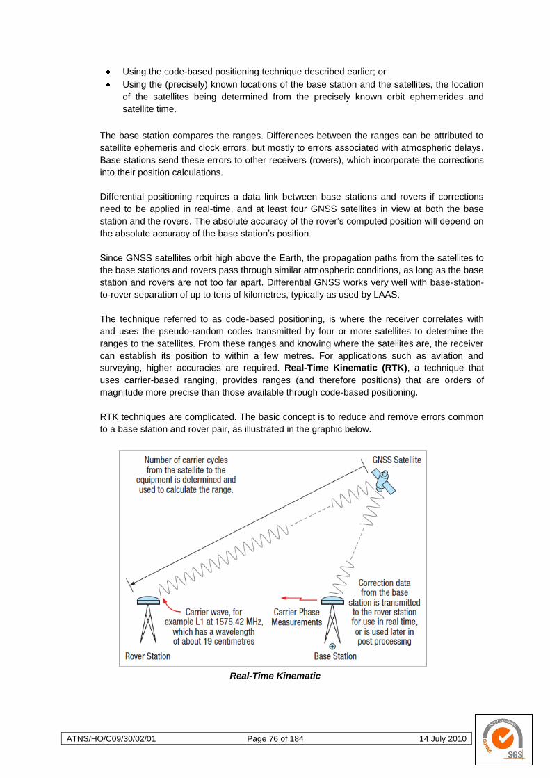
ATNS/HO/C09/30/02/01 Page 76 of 184 14 July 2010
Using the code-based positioning technique described earlier; or
Using the (precisely) known locations of the base station and the satellites, the location
of the satellites being determined from the precisely known orbit ephemerides and
satellite time.
The base station compares the ranges. Differences between the ranges can be attributed to
satellite ephemeris and clock errors, but mostly to errors associated with atmospheric delays.
Base stations send these errors to other receivers (rovers), which incorporate the corrections
into their position calculations.
Differential positioning requires a data link between base stations and rovers if corrections
need to be applied in real-time, and at least four GNSS satellites in view at both the base
station and the rovers. The absolute accuracy of the rover‘s computed position will depend on
the absolute accuracy of the base station‘s position.
Since GNSS satellites orbit high above the Earth, the propagation paths from the satellites to
the base stations and rovers pass through similar atmospheric conditions, as long as the base
station and rovers are not too far apart. Differential GNSS works very well with base-station-
to-rover separation of up to tens of kilometres, typically as used by LAAS.
The technique referred to as code-based positioning, is where the receiver correlates with
and uses the pseudo-random codes transmitted by four or more satellites to determine the
ranges to the satellites. From these ranges and knowing where the satellites are, the receiver
can establish its position to within a few metres. For applications such as aviation and
surveying, higher accuracies are required. Real-Time Kinematic (RTK), a technique that
uses carrier-based ranging, provides ranges (and therefore positions) that are orders of
magnitude more precise than those available through code-based positioning.
RTK techniques are complicated. The basic concept is to reduce and remove errors common
to a base station and rover pair, as illustrated in the graphic below.
Real-Time Kinematic
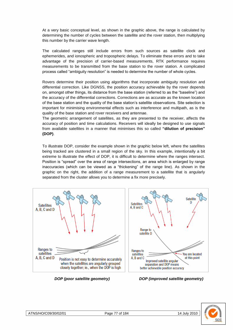
ATNS/HO/C09/30/02/01 Page 77 of 184 14 July 2010
At a very basic conceptual level, as shown in the graphic above, the range is calculated by
determining the number of cycles between the satellite and the rover station, then multiplying
this number by the carrier wave length.
The calculated ranges still include errors from such sources as satellite clock and
ephemerides, and ionospheric and tropospheric delays. To eliminate these errors and to take
advantage of the precision of carrier-based measurements, RTK performance requires
measurements to be transmitted from the base station to the rover station. A complicated
process called ―ambiguity resolution‖ is needed to determine the number of whole cycles.
Rovers determine their position using algorithms that incorporate ambiguity resolution and
differential correction. Like DGNSS, the position accuracy achievable by the rover depends
on, amongst other things, its distance from the base station (referred to as the ―baseline‖) and
the accuracy of the differential corrections. Corrections are as accurate as the known location
of the base station and the quality of the base station‘s satellite observations. Site selection is
important for minimising environmental effects such as interference and multipath, as is the
quality of the base station and rover receivers and antennae.
The geometric arrangement of satellites, as they are presented to the receiver, affects the
accuracy of position and time calculations. Receivers will ideally be designed to use signals
from available satellites in a manner that minimises this so called ―dilution of precision‖
(DOP).
To illustrate DOP, consider the example shown in the graphic below left, where the satellites
being tracked are clustered in a small region of the sky. In this example, intentionally a bit
extreme to illustrate the effect of DOP, it is difficult to determine where the ranges intersect.
Position is ―spread‖ over the area of range intersections, an area which is enlarged by range
inaccuracies (which can be viewed as a ―thickening‖ of the range line). As shown in the
graphic on the right, the addition of a range measurement to a satellite that is angularly
separated from the cluster allows you to determine a fix more precisely.
DOP (poor satellite geometry) DOP (improved satellite geometry)
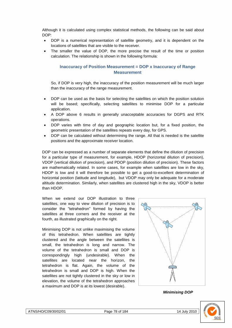
ATNS/HO/C09/30/02/01 Page 78 of 184 14 July 2010
Although it is calculated using complex statistical methods, the following can be said about
DOP:
DOP is a numerical representation of satellite geometry, and it is dependent on the
locations of satellites that are visible to the receiver.
The smaller the value of DOP, the more precise the result of the time or position
calculation. The relationship is shown in the following formula:
Inaccuracy of Position Measurement = DOP x Inaccuracy of Range
Measurement
So, if DOP is very high, the inaccuracy of the position measurement will be much larger
than the inaccuracy of the range measurement.
DOP can be used as the basis for selecting the satellites on which the position solution
will be based; specifically, selecting satellites to minimise DOP for a particular
application.
A DOP above 6 results in generally unacceptable accuracies for DGPS and RTK
operations.
DOP varies with time of day and geographic location but, for a fixed position, the
geometric presentation of the satellites repeats every day, for GPS.
DOP can be calculated without determining the range. All that is needed is the satellite
positions and the approximate receiver location.
DOP can be expressed as a number of separate elements that define the dilution of precision
for a particular type of measurement, for example, HDOP (horizontal dilution of precision),
VDOP (vertical dilution of precision), and PDOP (position dilution of precision). These factors
are mathematically related. In some cases, for example when satellites are low in the sky,
HDOP is low and it will therefore be possible to get a good-to-excellent determination of
horizontal position (latitude and longitude), but VDOP may only be adequate for a moderate
altitude determination. Similarly, when satellites are clustered high in the sky, VDOP is better
than HDOP.
When we extend our DOP illustration to three
satellites, one way to view dilution of precision is to
consider the ―tetrahedron‖ formed by having the
satellites at three corners and the receiver at the
fourth, as illustrated graphically on the right.
Minimising DOP is not unlike maximising the volume
of this tetrahedron. When satellites are tightly
clustered and the angle between the satellites is
small, the tetrahedron is long and narrow. The
volume of the tetrahedron is small and DOP is
correspondingly high (undesirable). When the
satellites are located near the horizon, the
tetrahedron is flat. Again, the volume of the
tetrahedron is small and DOP is high. When the
satellites are not tightly clustered in the sky or low in
elevation, the volume of the tetrahedron approaches
a maximum and DOP is at its lowest (desirable).
Minimising DOP

ATNS/HO/C09/30/02/01 Page 79 of 184 14 July 2010
Northrop-Grumman LN-100R
Embedded INS/GPS
In Canada and other countries at high latitude, GNSS satellites are lower in the sky, and
achieving optimal DOP for some applications, particularly where good VDOP is required, is
sometimes a challenge.
When there were fewer GNSS satellites, achieving good DOP was sometimes difficult. These
difficulties are being reduced with more GNSS constellations and satellites coming on line
every year. Applications where the available satellites are low on the horizon or angularly
clustered may still expose the user to the pitfalls of
DOP. If you know your application will have
obstructed conditions, you may want to use a mission
planning tool in assist in your flight planning.
As discussed, GNSS use signals from orbiting
satellites to compute position, time and velocity.
GNSS navigation has excellent accuracy provided
the antenna has good visibility to the satellites. When
the line-of-sight to the satellites is blocked by
obstructions such as severe cloud cover, navigation
becomes unreliable or impossible. Inertial
Navigation System (INS) use rotation and
acceleration information from an Inertial
Measurement Unit (IMU) to compute accurate
position over time. An INS can also solve the attitude (roll, pitch and heading) of a vessel and
is not reliant on any external measurement to compute solution. In the absence of external
reference, however, the INS solution drifts over time due to accumulating errors in the IMU
data. When combined, the two techniques (GNSS and INS) enhance each other to provide a
powerful navigation solution.
The degree with which the GNSS and INS technologies are integrated varies with product
implementation. For example, in tightly coupled solutions, GNSS observations are used
directly by the inertial solution to take advantage of available GNSS data, even when only a
few satellites are visible (for instance, to reset or adjust the position being input by the INS).
Tightly coupled solutions allow feedback of the inertial solution into the GNSS receiver to
improve GNSS performance, for example, signal acquisition and convergence time. To
summarise, combining GNSS and INS technologies significantly increases opportunities for
application development by overcoming the limitations of the individual technologies.
2.3.6 GNSS Liability
In the development of GNSS, liability relating to signal accuracy and continuity is an issue that
is often raised; however, there is currently no satisfactory solution to this problem (see note
on the next page). Even in regulatory agencies there seems to be confusion about the status
of GNSS, but they accept the partial certification of GNSS products and related services. The
facts are that GNSS is in use in Civil Aviation today and aircraft are being supplied with
related installations and certified to ―near CAT I‖ levels. However, the use of GNSS in Public
Transport Operations still raises concern, largely because of the potential consequences of a
GNSS failure. Despite this, liability still appears relatively low on the agenda, since it is widely
assumed that these issues will be resolved when ―appropriate‖ institutional arrangements are
put in place by the ICAO. Yet, whether this is a realistic expectation seems very unclear.
ATNS/HO/C09/30/02/01 Page 80 of 184 14 July 2010
Note: — The liability issues regarding signal accuracy and continuity is currently addressed
through augmentation requirements. This is seen as the only effective means of
addressing this issue.
GNSS raises technical, commercial, political, military, institutional and legal issues. There are
many factors that must be taken into account in order to navigate through the potential
minefield that lies in the path of user airliner, airports, ATM providers, manufacturers and
individual States as they make strategic decisions that will affect their businesses in
generations to come.
Issues such as liability, certification, etc. are not just
purely altruistic considerations. GNSS is not a system
designed solely or specifically for civil aviation. GNSS
has many wide ranging applications across all
industry sectors and its applications are not just
limited to navigation. Indeed, no Civil Aviation
Authority or group of CAAs could muster even a tiny
fraction of the resources that are required to launch a
GNSS. The list of applications and the value of these
applications is so great, that the civil aviation market
is actually small by comparison, but still very large. This is one of the keys to the problem:
GNSS is a generic service of huge commercial significance.
The ICAO generally requires its members to accept the certification given by other States to
its own navigation services and that the ICAO members accept the certification given by a
member State to its registered aircraft and licensed crew.
The ICAO is setting standards for both GNSS and GNSS-based services. These standards
naturally assumed a GPS-like service. Thus the ICAO is essentially ―retro-fitting‖ standards to
an existing service (and assuming some upgrading of those services). Theoretically speaking,
the ICAO‘s role is simply to set safety and interoperability standards. In reality, the ICAO‘s
actual role in GNSS standardisation is a little anomalous, as it appears to be taking a lead (in
defining standards) when so many other sectors have a possibly greater interest. This is, in
part, based on the assumption that aviation is the most demanding user in safety.
Indeed, many have assumed that GNSS would somehow be ―approved‖ by the ICAO;
however, this UN Institution has no power or precedent for giving any approval that would be
legally effective. The ICAO is more a forum for agreeing common standards and settling
relations on civil aviation matters between its members. It is not an Agency with any
delegated power to carry out approvals; these are the sovereign responsibilities of the
member States. In reality, the ICAO concentrates on the interoperability of GNSS (to prevent
divergent satellite navigation systems) and the safety of augmentation systems (provided by
civil aviation).
However, legal liability has to be assured in some way to protect the interests of the civil
community in the event of a serious GNSS failure. Conversely, steps would also have to be
taken to protect a GNSS provider from hostile legal measures following a major accident or
disaster linked to its services.
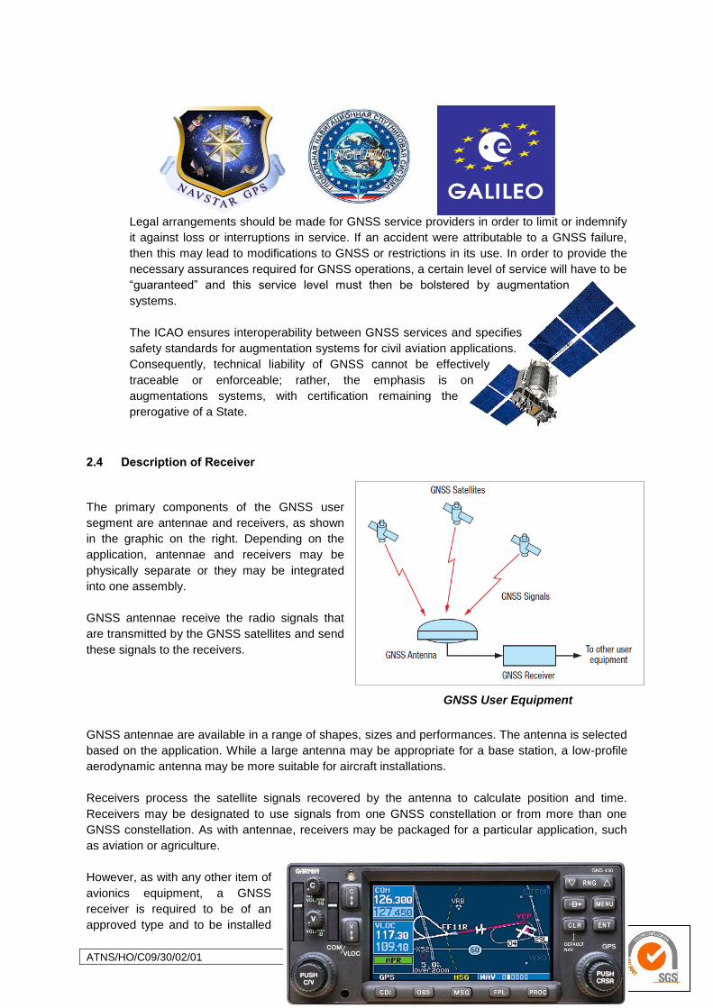
ATNS/HO/C09/30/02/01 Page 81 of 184 14 July 2010
Legal arrangements should be made for GNSS service providers in order to limit or indemnify
it against loss or interruptions in service. If an accident were attributable to a GNSS failure,
then this may lead to modifications to GNSS or restrictions in its use. In order to provide the
necessary assurances required for GNSS operations, a certain level of service will have to be
―guaranteed‖ and this service level must then be bolstered by augmentation
systems.
The ICAO ensures interoperability between GNSS services and specifies
safety standards for augmentation systems for civil aviation applications.
Consequently, technical liability of GNSS cannot be effectively
traceable or enforceable; rather, the emphasis is on
augmentations systems, with certification remaining the
prerogative of a State.
2.4 Description of Receiver
The primary components of the GNSS user
segment are antennae and receivers, as shown
in the graphic on the right. Depending on the
application, antennae and receivers may be
physically separate or they may be integrated
into one assembly.
GNSS antennae receive the radio signals that
are transmitted by the GNSS satellites and send
these signals to the receivers.
GNSS User Equipment
GNSS antennae are available in a range of shapes, sizes and performances. The antenna is selected
based on the application. While a large antenna may be appropriate for a base station, a low-profile
aerodynamic antenna may be more suitable for aircraft installations.
Receivers process the satellite signals recovered by the antenna to calculate position and time.
Receivers may be designated to use signals from one GNSS constellation or from more than one
GNSS constellation. As with antennae, receivers may be packaged for a particular application, such
as aviation or agriculture.
However, as with any other item of
avionics equipment, a GNSS
receiver is required to be of an
approved type and to be installed
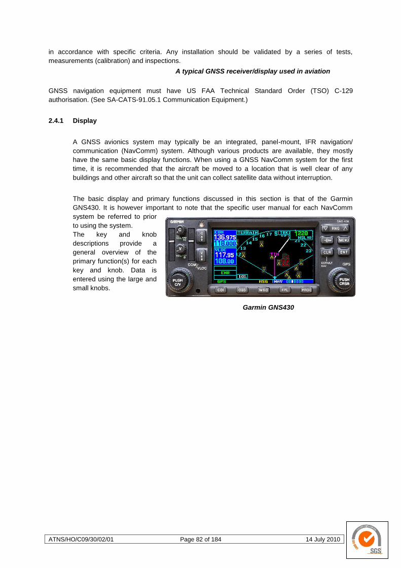
ATNS/HO/C09/30/02/01 Page 82 of 184 14 July 2010
in accordance with specific criteria. Any installation should be validated by a series of tests,
measurements (calibration) and inspections.
A typical GNSS receiver/display used in aviation
GNSS navigation equipment must have US FAA Technical Standard Order (TSO) C-129
authorisation. (See SA-CATS-91.05.1 Communication Equipment.)
2.4.1 Display
A GNSS avionics system may typically be an integrated, panel-mount, IFR navigation/
communication (NavComm) system. Although various products are available, they mostly
have the same basic display functions. When using a GNSS NavComm system for the first
time, it is recommended that the aircraft be moved to a location that is well clear of any
buildings and other aircraft so that the unit can collect satellite data without interruption.
The basic display and primary functions discussed in this section is that of the Garmin
GNS430. It is however important to note that the specific user manual for each NavComm
system be referred to prior
to using the system.
The key and knob
descriptions provide a
general overview of the
primary function(s) for each
key and knob. Data is
entered using the large and
small knobs.
Garmin GNS430
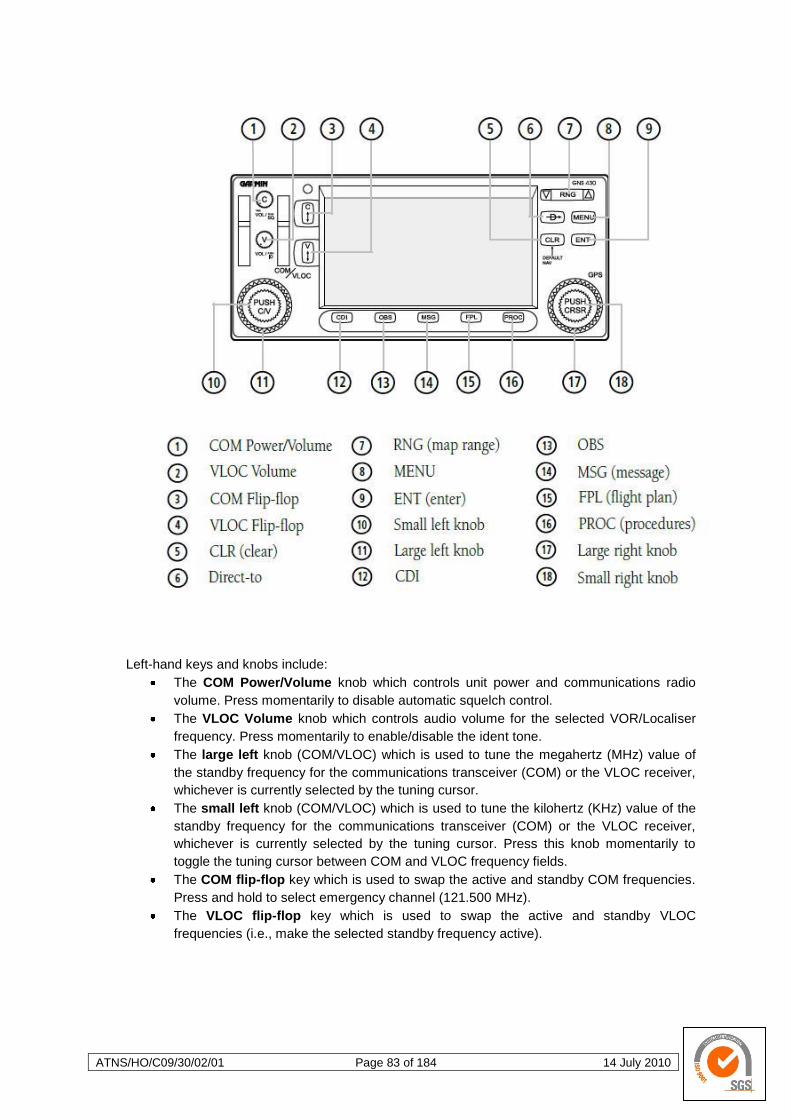
ATNS/HO/C09/30/02/01 Page 83 of 184 14 July 2010
Left-hand keys and knobs include:
The COM Power/Volume knob which controls unit power and communications radio
volume. Press momentarily to disable automatic squelch control.
The VLOC Volume knob which controls audio volume for the selected VOR/Localiser
frequency. Press momentarily to enable/disable the ident tone.
The large left knob (COM/VLOC) which is used to tune the megahertz (MHz) value of
the standby frequency for the communications transceiver (COM) or the VLOC receiver,
whichever is currently selected by the tuning cursor.
The small left knob (COM/VLOC) which is used to tune the kilohertz (KHz) value of the
standby frequency for the communications transceiver (COM) or the VLOC receiver,
whichever is currently selected by the tuning cursor. Press this knob momentarily to
toggle the tuning cursor between COM and VLOC frequency fields.
The COM flip-flop key which is used to swap the active and standby COM frequencies.
Press and hold to select emergency channel (121.500 MHz).
The VLOC flip-flop key which is used to swap the active and standby VLOC
frequencies (i.e., make the selected standby frequency active).
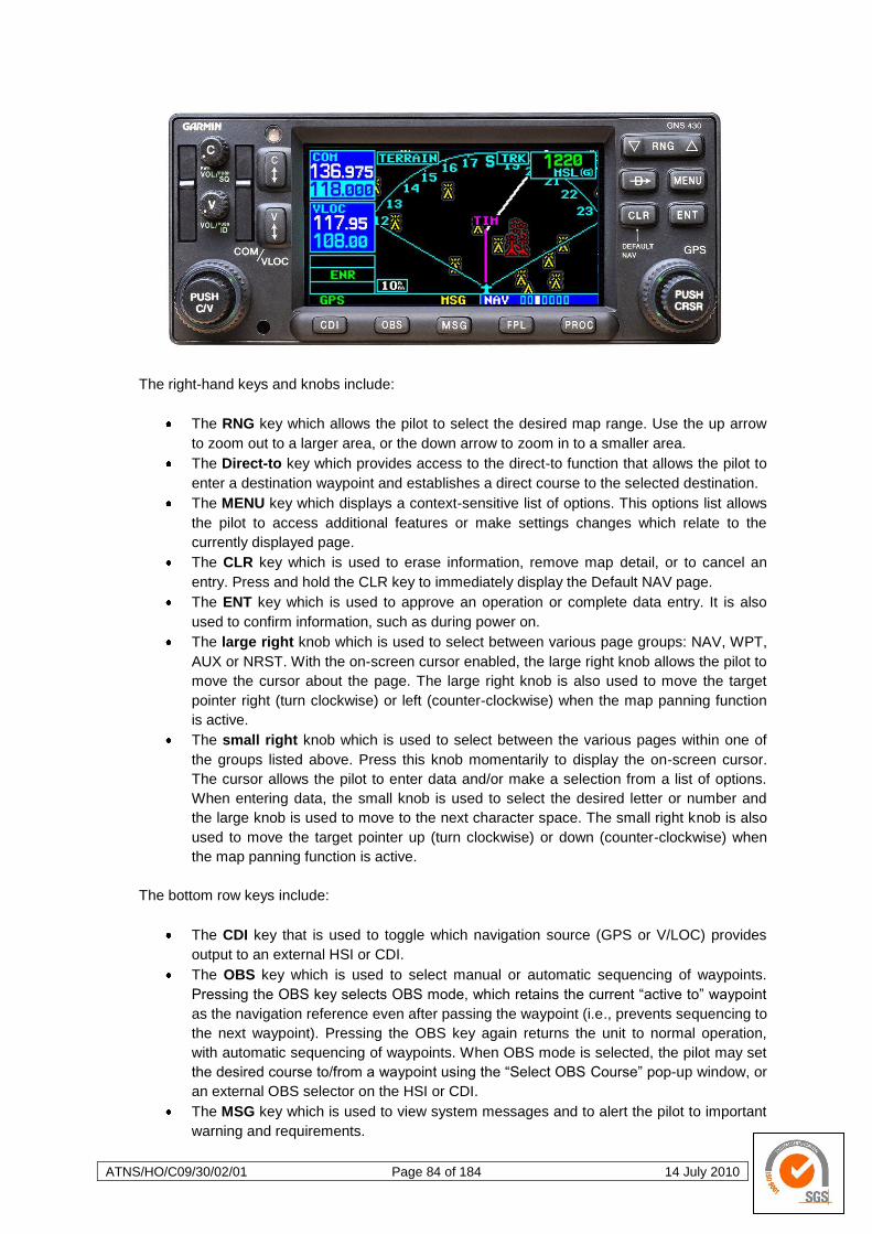
ATNS/HO/C09/30/02/01 Page 84 of 184 14 July 2010
The right-hand keys and knobs include:
The RNG key which allows the pilot to select the desired map range. Use the up arrow
to zoom out to a larger area, or the down arrow to zoom in to a smaller area.
The Direct-to key which provides access to the direct-to function that allows the pilot to
enter a destination waypoint and establishes a direct course to the selected destination.
The MENU key which displays a context-sensitive list of options. This options list allows
the pilot to access additional features or make settings changes which relate to the
currently displayed page.
The CLR key which is used to erase information, remove map detail, or to cancel an
entry. Press and hold the CLR key to immediately display the Default NAV page.
The ENT key which is used to approve an operation or complete data entry. It is also
used to confirm information, such as during power on.
The large right knob which is used to select between various page groups: NAV, WPT,
AUX or NRST. With the on-screen cursor enabled, the large right knob allows the pilot to
move the cursor about the page. The large right knob is also used to move the target
pointer right (turn clockwise) or left (counter-clockwise) when the map panning function
is active.
The small right knob which is used to select between the various pages within one of
the groups listed above. Press this knob momentarily to display the on-screen cursor.
The cursor allows the pilot to enter data and/or make a selection from a list of options.
When entering data, the small knob is used to select the desired letter or number and
the large knob is used to move to the next character space. The small right knob is also
used to move the target pointer up (turn clockwise) or down (counter-clockwise) when
the map panning function is active.
The bottom row keys include:
The CDI key that is used to toggle which navigation source (GPS or V/LOC) provides
output to an external HSI or CDI.
The OBS key which is used to select manual or automatic sequencing of waypoints.
Pressing the OBS key selects OBS mode, which retains the current ―active to‖ waypoint
as the navigation reference even after passing the waypoint (i.e., prevents sequencing to
the next waypoint). Pressing the OBS key again returns the unit to normal operation,
with automatic sequencing of waypoints. When OBS mode is selected, the pilot may set
the desired course to/from a waypoint using the ―Select OBS Course‖ pop-up window, or
an external OBS selector on the HSI or CDI.
The MSG key which is used to view system messages and to alert the pilot to important
warning and requirements.
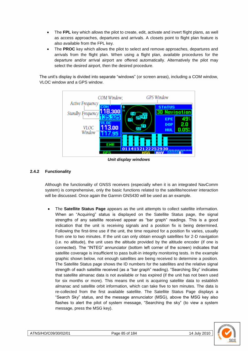
ATNS/HO/C09/30/02/01 Page 85 of 184 14 July 2010
The FPL key which allows the pilot to create, edit, activate and invert flight plans, as well
as access approaches, departures and arrivals. A closets point to flight plan feature is
also available from the FPL key.
The PROC key which allows the pilot to select and remove approaches, departures and
arrivals from the flight plan. When using a flight plan, available procedures for the
departure and/or arrival airport are offered automatically. Alternatively the pilot may
select the desired airport, then the desired procedure.
The unit‘s display is divided into separate ―windows‖ (or screen areas), including a COM window,
VLOC window and a GPS window.
Unit display windows
2.4.2 Functionality
Although the functionality of GNSS receivers (especially when it is an integrated NavComm
system) is comprehensive, only the basic functions related to the satellite/receiver interaction
will be discussed. Once again the Garmin GNS430 will be used as an example.
The Satellite Status Page appears as the unit attempts to collect satellite information.
When an ―Acquiring‖ status is displayed on the Satellite Status page, the signal
strengths of any satellite received appear as ―bar graph‖ readings. This is a good
indication that the unit is receiving signals and a position fix is being determined.
Following the first-time use if the unit, the time required for a position fix varies, usually
from one to two minutes. If the unit can only obtain enough satellites for 2-D navigation
(i.e. no altitude), the unit uses the altitude provided by the altitude encoder (if one is
connected). The ―INTEG‖ annunciator (bottom left corner of the screen) indicates that
satellite coverage is insufficient to pass built-in integrity monitoring tests. In the example
graphic shown below, not enough satellites are being received to determine a position.
The Satellite Status page shows the ID numbers for the satellites and the relative signal
strength of each satellite received (as a ―bar graph‖ reading). ―Searching Sky‖ indicates
that satellite almanac data is not available or has expired (if the unit has not been used
for six months or more). This means the unit is acquiring satellite data to establish
almanac and satellite orbit information, which can take five to ten minutes. The data is
re-collected from the first available satellite. The Satellite Status Page displays a
―Search Sky‖ status, and the message annunciator (MSG), above the MSG key also
flashes to alert the pilot of system message, ―Searching the sky‖ (to view a system
message, press the MSG key).

ATNS/HO/C09/30/02/01 Page 86 of 184 14 July 2010
Satellite Status Page Message
Page
The Satellite Status Page also provides a visual reference of GPS receiver functions,
including current satellite coverage, GPS receiver status and position accuracy. This
page is also helpful in troubleshooting weak (or missing) signal levels due to poor
satellite coverage or installation problems.
Satellite Status Page Annotations
As the GPS receiver locks onto satellites, a signal bar appears for each satellite in view,
with the appropriate satellite number underneath each bar. The progress of satellite
acquisition is shown in three stages:
No signal strength bar – the receiver is looking for the satellites indicated;
Hollow signal strength bars – the receiver has found the satellite(s) and is collecting
data;
Solid signal strength bars – the receiver has collected the necessary data and the
satellite(s) is ready for use.
Chequered signal strength bars – Excluded satellites.
The sky view display (at top left corner of the page) shows which satellites are currently in
view, and where they are. The outer circle of the sky view represents the horizon (with north
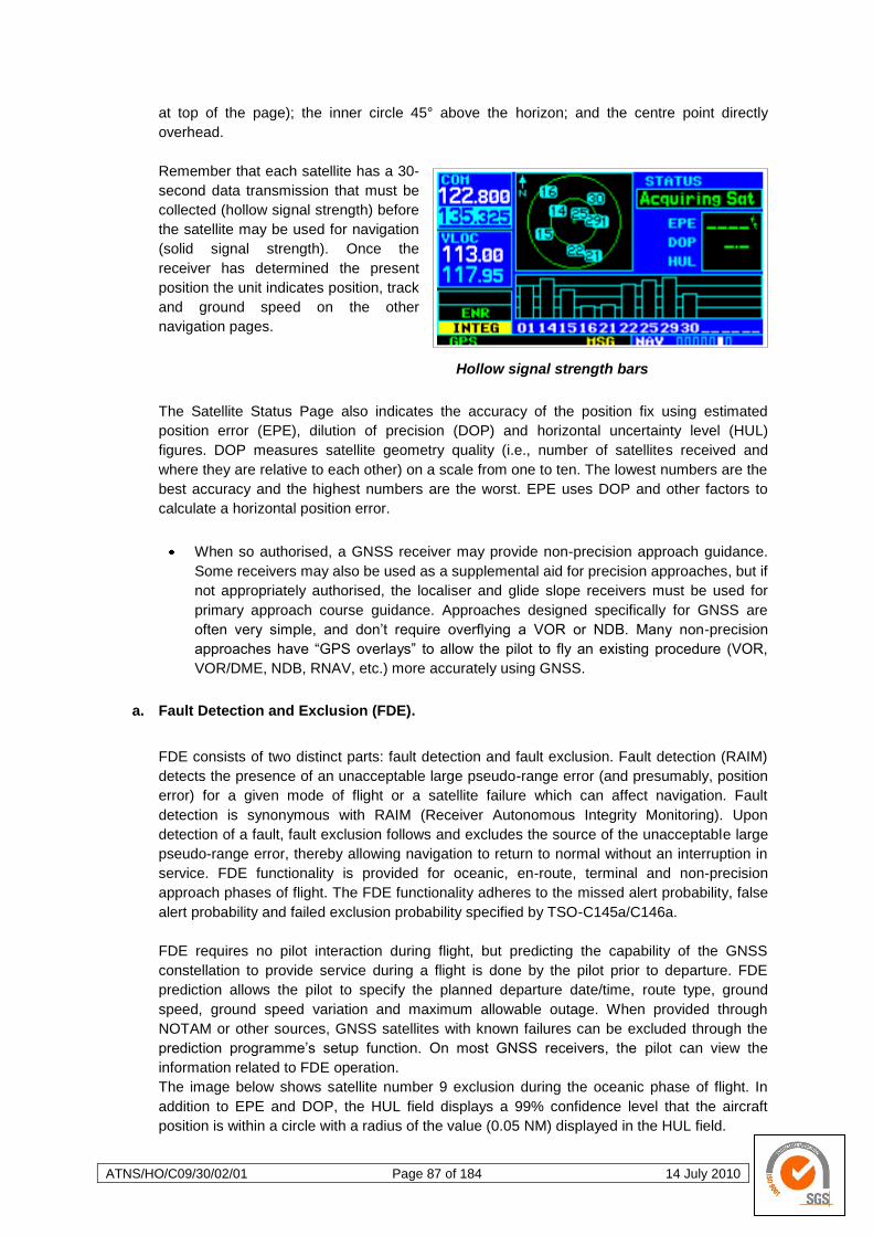
ATNS/HO/C09/30/02/01 Page 87 of 184 14 July 2010
at top of the page); the inner circle 45° above the horizon; and the centre point directly
overhead.
Remember that each satellite has a 30-
second data transmission that must be
collected (hollow signal strength) before
the satellite may be used for navigation
(solid signal strength). Once the
receiver has determined the present
position the unit indicates position, track
and ground speed on the other
navigation pages.
Hollow signal strength bars
The Satellite Status Page also indicates the accuracy of the position fix using estimated
position error (EPE), dilution of precision (DOP) and horizontal uncertainty level (HUL)
figures. DOP measures satellite geometry quality (i.e., number of satellites received and
where they are relative to each other) on a scale from one to ten. The lowest numbers are the
best accuracy and the highest numbers are the worst. EPE uses DOP and other factors to
calculate a horizontal position error.
When so authorised, a GNSS receiver may provide non-precision approach guidance.
Some receivers may also be used as a supplemental aid for precision approaches, but if
not appropriately authorised, the localiser and glide slope receivers must be used for
primary approach course guidance. Approaches designed specifically for GNSS are
often very simple, and don‘t require overflying a VOR or NDB. Many non-precision
approaches have ―GPS overlays‖ to allow the pilot to fly an existing procedure (VOR,
VOR/DME, NDB, RNAV, etc.) more accurately using GNSS.
a. Fault Detection and Exclusion (FDE).
FDE consists of two distinct parts: fault detection and fault exclusion. Fault detection (RAIM)
detects the presence of an unacceptable large pseudo-range error (and presumably, position
error) for a given mode of flight or a satellite failure which can affect navigation. Fault
detection is synonymous with RAIM (Receiver Autonomous Integrity Monitoring). Upon
detection of a fault, fault exclusion follows and excludes the source of the unacceptable large
pseudo-range error, thereby allowing navigation to return to normal without an interruption in
service. FDE functionality is provided for oceanic, en-route, terminal and non-precision
approach phases of flight. The FDE functionality adheres to the missed alert probability, false
alert probability and failed exclusion probability specified by TSO-C145a/C146a.
FDE requires no pilot interaction during flight, but predicting the capability of the GNSS
constellation to provide service during a flight is done by the pilot prior to departure. FDE
prediction allows the pilot to specify the planned departure date/time, route type, ground
speed, ground speed variation and maximum allowable outage. When provided through
NOTAM or other sources, GNSS satellites with known failures can be excluded through the
prediction programme‘s setup function. On most GNSS receivers, the pilot can view the
information related to FDE operation.
The image below shows satellite number 9 exclusion during the oceanic phase of flight. In
addition to EPE and DOP, the HUL field displays a 99% confidence level that the aircraft
position is within a circle with a radius of the value (0.05 NM) displayed in the HUL field.
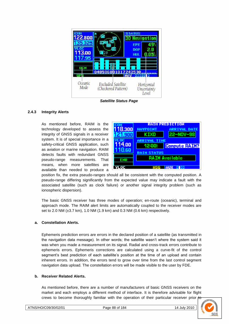
ATNS/HO/C09/30/02/01 Page 88 of 184 14 July 2010
Satellite Status Page
2.4.3 Integrity Alerts
As mentioned before, RAIM is the
technology developed to assess the
integrity of GNSS signals in a receiver
system. It is of special importance in a
safety-critical GNSS application, such
as aviation or marine navigation. RAIM
detects faults with redundant GNSS
pseudo-range measurements. That
means, when more satellites are
available than needed to produce a
position fix, the extra pseudo-ranges should all be consistent with the computed position. A
pseudo-range differing significantly from the expected value may indicate a fault with the
associated satellite (such as clock failure) or another signal integrity problem (such as
ionospheric dispersion).
The basic GNSS receiver has three modes of operation; en-route (oceanic), terminal and
approach mode. The RAIM alert limits are automatically coupled to the receiver modes are
set to 2.0 NM (±3.7 km), 1.0 NM (1.9 km) and 0.3 NM (0.6 km) respectively.
a. Constellation Alerts.
Ephemeris prediction errors are errors in the declared position of a satellite (as transmitted in
the navigation data message). In other words; the satellite wasn‘t where the system said it
was when you made a measurement on its signal. Radial and cross-track errors contribute to
ephemeris errors. Ephemeris corrections are calculated using a curve-fit of the control
segment‘s best prediction of each satellite‘s position at the time of an upload and contain
inherent errors. In addition, the errors tend to grow over time from the last control segment
navigation data upload. The constellation errors will be made visible to the user by FDE.
b. Receiver Related Alerts.
As mentioned before, there are a number of manufacturers of basic GNSS receivers on the
market and each employs a different method of interface. It is therefore advisable for flight
crews to become thoroughly familiar with the operation of their particular receiver prior to
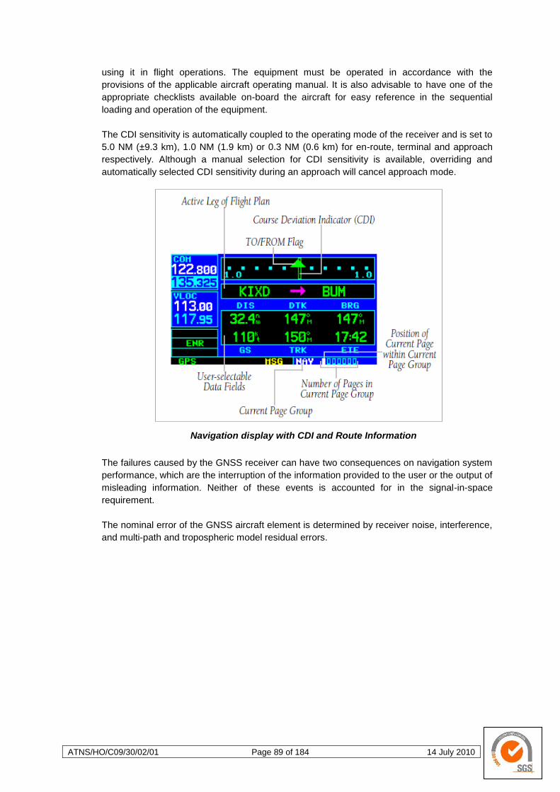
ATNS/HO/C09/30/02/01 Page 89 of 184 14 July 2010
using it in flight operations. The equipment must be operated in accordance with the
provisions of the applicable aircraft operating manual. It is also advisable to have one of the
appropriate checklists available on-board the aircraft for easy reference in the sequential
loading and operation of the equipment.
The CDI sensitivity is automatically coupled to the operating mode of the receiver and is set to
5.0 NM (±9.3 km), 1.0 NM (1.9 km) or 0.3 NM (0.6 km) for en-route, terminal and approach
respectively. Although a manual selection for CDI sensitivity is available, overriding and
automatically selected CDI sensitivity during an approach will cancel approach mode.
Navigation display with CDI and Route Information
The failures caused by the GNSS receiver can have two consequences on navigation system
performance, which are the interruption of the information provided to the user or the output of
misleading information. Neither of these events is accounted for in the signal-in-space
requirement.
The nominal error of the GNSS aircraft element is determined by receiver noise, interference,
and multi-path and tropospheric model residual errors.
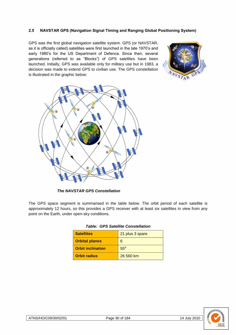
ATNS/HO/C09/30/02/01 Page 90 of 184 14 July 2010
2.5 NAVSTAR GPS (Navigation Signal Timing and Ranging Global Positioning System)
GPS was the first global navigation satellite system. GPS (or NAVSTAR,
as it is officially called) satellites were first launched in the late 1970‘s and
early 1980‘s for the US Department of Defence. Since then, several
generations (referred to as ―Blocks‖) of GPS satellites have been
launched. Initially, GPS was available only for military use but in 1983, a
decision was made to extend GPS to civilian use. The GPS constellation
is illustrated in the graphic below:
The NAVSTAR GPS Constellation
The GPS space segment is summarised in the table below. The orbit period of each satellite is
approximately 12 hours, so this provides a GPS receiver with at least six satellites in view from any
point on the Earth, under open-sky conditions.
Table: GPS Satellite Constellation
Satellites 21 plus 3 spare
Orbital planes 6
Orbit inclination 55⁰
Orbit radius 26 560 km
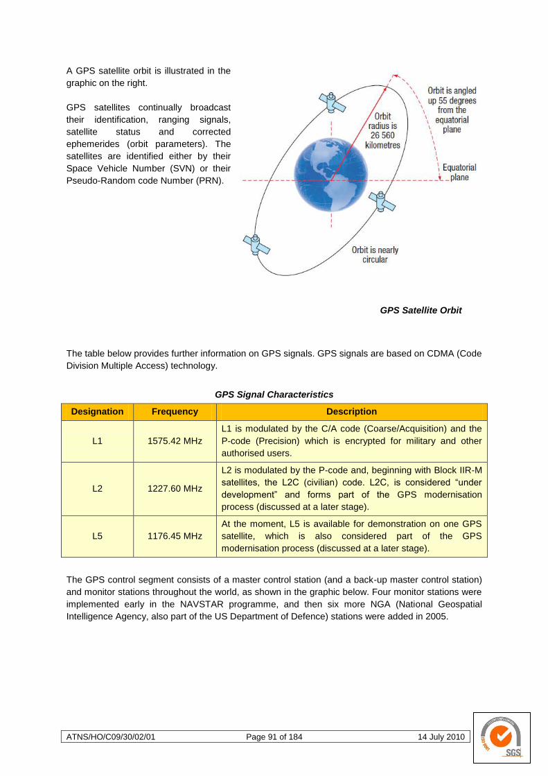
ATNS/HO/C09/30/02/01 Page 91 of 184 14 July 2010
A GPS satellite orbit is illustrated in the
graphic on the right.
GPS satellites continually broadcast
their identification, ranging signals,
satellite status and corrected
ephemerides (orbit parameters). The
satellites are identified either by their
Space Vehicle Number (SVN) or their
Pseudo-Random code Number (PRN).
GPS Satellite Orbit
The table below provides further information on GPS signals. GPS signals are based on CDMA (Code
Division Multiple Access) technology.
GPS Signal Characteristics
Designation Frequency Description
L1 1575.42 MHz
L1 is modulated by the C/A code (Coarse/Acquisition) and the
P-code (Precision) which is encrypted for military and other
authorised users.
L2 1227.60 MHz
L2 is modulated by the P-code and, beginning with Block IIR-M
satellites, the L2C (civilian) code. L2C, is considered ―under
development‖ and forms part of the GPS modernisation
process (discussed at a later stage).
L5 1176.45 MHz
At the moment, L5 is available for demonstration on one GPS
satellite, which is also considered part of the GPS
modernisation process (discussed at a later stage).
The GPS control segment consists of a master control station (and a back-up master control station)
and monitor stations throughout the world, as shown in the graphic below. Four monitor stations were
implemented early in the NAVSTAR programme, and then six more NGA (National Geospatial
Intelligence Agency, also part of the US Department of Defence) stations were added in 2005.

ATNS/HO/C09/30/02/01 Page 92 of 184 14 July 2010
The monitor stations track the satellites via their broadcast signals, which contain satellite ephemeris
data, ranging signals, clock data and almanac data. These signals are passed to the master control
station where the ephemerides are re-calculated. The resulting ephemeride and timing corrections are
transmitted back up to the satellites through data up-loading stations.
GPS Control Segment
GPS reached Fully Operational Capability in 1995. In 2000, a project was initiated to modernise the
GPS space and ground segments, to take advantage of new technologies and user requirements.
Space segment modernisation has included new signals, as well as improvements in atomic clock
accuracy, satellite signal strength and reliability. Control segment modernisation includes improved
ionospheric and tropospheric modelling and in-orbit accuracy, and additional monitoring stations. User
requirement has also evolved, to take advantage of space and control segments improvement.
The latest generation of GPS satellites has the capability to transmit a new civilian signal, designated
L2C. Once operational, L2C will ensure the accessibility of two civilian codes. L2C will be easier for
the user segment to track and it will provide improved navigation accuracy. It will also provide the
ability to directly measure and remove ionospheric delay error for a particular satellite, using the
civilian signals on both L1 and L2.
The US has started implementing a third civil GPS frequency (L5) at 1176.45 MHz. The first
NAVSTAR GPS satellite to transmit L5, on a demonstration basis, was launched in 2009. The
benefits of the L5 signal include meeting the requirements for critical safety-of-life applications such
as that needed for civil aviation, and providing improved ionospheric correction, signal redundancy,
improved signal accuracy and improved interference rejection.
In addition to the new L2C and L5 signals, GPS satellite modernisation includes a new military signal
and an improved L1C which will be backward compatible with L1 and which will provide greater
civilian interoperability with Galileo.
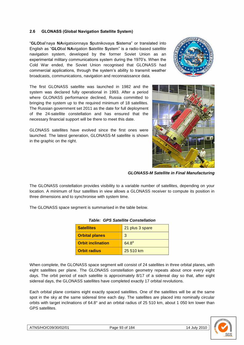
ATNS/HO/C09/30/02/01 Page 93 of 184 14 July 2010
2.6 GLONASS (Global Navigation Satellite System)
―GLObal‘naya NAvigatsionnaya Sputnikovaya Sistema‖ or translated into
English as ―GLObal NAvigation Satellite System‖ is a radio-based satellite
navigation system, developed by the former Soviet Union as an
experimental military communications system during the 1970‘s. When the
Cold War ended, the Soviet Union recognised that GLONASS had
commercial applications, through the system‘s ability to transmit weather
broadcasts, communications, navigation and reconnaissance data.
The first GLONASS satellite was launched in 1982 and the
system was declared fully operational in 1993. After a period
where GLONASS performance declined, Russia committed to
bringing the system up to the required minimum of 18 satellites.
The Russian government set 2011 as the date for full deployment
of the 24-satellite constellation and has ensured that the
necessary financial support will be there to meet this date.
GLONASS satellites have evolved since the first ones were
launched. The latest generation, GLONASS-M satellite is shown
in the graphic on the right.
GLONASS-M Satellite in Final Manufacturing
The GLONASS constellation provides visibility to a variable number of satellites, depending on your
location. A minimum of four satellites in view allows a GLONASS receiver to compute its position in
three dimensions and to synchronise with system time.
The GLONASS space segment is summarised in the table below.
Table: GPS Satellite Constellation
Satellites 21 plus 3 spare
Orbital planes 3
Orbit inclination 64.8⁰
Orbit radius 25 510 km
When complete, the GLONASS space segment will consist of 24 satellites in three orbital planes, with
eight satellites per plane. The GLONASS constellation geometry repeats about once every eight
days. The orbit period of each satellite is approximately 8/17 of a sidereal day so that, after eight
sidereal days, the GLONASS satellites have completed exactly 17 orbital revolutions.
Each orbital plane contains eight exactly spaced satellites. One of the satellites will be at the same
spot in the sky at the same sidereal time each day. The satellites are placed into nominally circular
orbits with target inclinations of 64.8° and an orbital radius of 25 510 km, about 1 050 km lower than
GPS satellites.
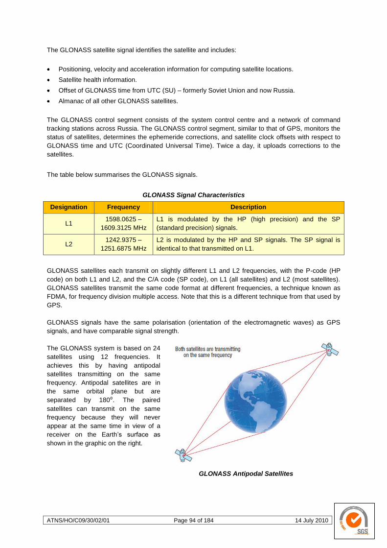
ATNS/HO/C09/30/02/01 Page 94 of 184 14 July 2010
The GLONASS satellite signal identifies the satellite and includes:
Positioning, velocity and acceleration information for computing satellite locations.
Satellite health information.
Offset of GLONASS time from UTC (SU) – formerly Soviet Union and now Russia.
Almanac of all other GLONASS satellites.
The GLONASS control segment consists of the system control centre and a network of command
tracking stations across Russia. The GLONASS control segment, similar to that of GPS, monitors the
status of satellites, determines the ephemeride corrections, and satellite clock offsets with respect to
GLONASS time and UTC (Coordinated Universal Time). Twice a day, it uploads corrections to the
satellites.
The table below summarises the GLONASS signals.
GLONASS Signal Characteristics
Designation Frequency Description
L1 1598.0625 –
1609.3125 MHz
L1 is modulated by the HP (high precision) and the SP
(standard precision) signals.
L2 1242.9375 –
1251.6875 MHz
L2 is modulated by the HP and SP signals. The SP signal is
identical to that transmitted on L1.
GLONASS satellites each transmit on slightly different L1 and L2 frequencies, with the P-code (HP
code) on both L1 and L2, and the C/A code (SP code), on L1 (all satellites) and L2 (most satellites).
GLONASS satellites transmit the same code format at different frequencies, a technique known as
FDMA, for frequency division multiple access. Note that this is a different technique from that used by
GPS.
GLONASS signals have the same polarisation (orientation of the electromagnetic waves) as GPS
signals, and have comparable signal strength.
The GLONASS system is based on 24
satellites using 12 frequencies. It
achieves this by having antipodal
satellites transmitting on the same
frequency. Antipodal satellites are in
the same orbital plane but are
separated by 180⁰. The paired
satellites can transmit on the same
frequency because they will never
appear at the same time in view of a
receiver on the Earth‘s surface as
shown in the graphic on the right.
GLONASS Antipodal Satellites

ATNS/HO/C09/30/02/01 Page 95 of 184 14 July 2010
The use of GLONASS in addition to GPS, results in there being a larger number of satellites in the
field of view, which has the following benefits:
Reduced signal acquisition time;
Improved position and time accuracy;
Reduction of problems caused by obstructions such
as buildings and foliage;
Improved spatial distribution of visible satellites,
resulting in improved dilution of precision (discussed
at a later stage).
To determine a position in GPS-only mode, a receiver
must track a minimum of four satellites. In combined
GPS/GLONASS mode, the receiver must track five
satellites, at least one of which must be a GLONASS
satellite so that the receiver can determine the
GPS/GLONASS time offset. With the availability of
combined GPS/GLONASS receivers, users have access
to a satellite combined system with over 40 satellites.
Performance in urban canyons and other locations with
restricted visibility improves as more satellites are
accessible by the receiver.
Combined GPS/GLONASS receiver
2.7 GALILEO (The name given to the European Global Navigation Satellite System)
Galileo, Europe‘s planned global navigation satellite system, will provide a
highly accurate and guaranteed global positioning system under civilian
control. The United States and European Union have been co-operating
since 2004 to ensure that GPS and Galileo are compatible and
interoperable at the user level.
By offering dual frequencies as standard, Galileo will deliver real-
time positioning accuracy down to the metre range, previously
not achievable by a publicly available system. Galileo will
guarantee availability of service under all but the most extreme
circumstances and it will inform users within seconds of a failure
of any satellite. This will make it suitable for applications where
safety is crucial, such as in air and ground transport.
The first experimental Galileo satellite (GIOVE-A), part of the
Galileo System Test Bed (GSTB) was launched in December
2005. The purpose of this experimental satellite is to characterise
critical Galileo technologies, which are already in development
under European Space Agency (ESA) contracts.
Preparing to launch the Soyuz-FG rocket with the Galileo satellite

ATNS/HO/C09/30/02/01 Page 96 of 184 14 July 2010
Four operational satellites are planned to be launched in the 2010-2012 time frame to validate the
basic Galileo space and ground segment. Once this In-Orbit Validation (IOV) phase has been
completed, the remaining satellites will be launched, with plans to reach Full Operational Capability
(FOC) likely sometime after 2013.
The Galileo space segment is summarised in the table below.
Table: GPS Satellite Constellation
Satellites 27 operational and 3 active spares
Orbital planes 3
Orbit inclination 56⁰
Orbit radius 23 616 km
Once the constellation is operational, Galileo navigational signals will provide coverage at all latitudes.
The large number of satellites, together with the optimisation of the constellation and the availability of
the three active spare satellites, will ensure that the loss of one satellite has no discernable effect on
the user segment.
Two Galileo Control Centres (GCC), which are to be located in Europe, will control the satellites. Data
recovered by a global network of twenty Galileo Sensor Stations (GSS) will be sent to the GCC
through a redundant communications network. The GCC will use data from the sensor stations to
compute integrity information and to synchronise satellite time with ground station clocks. Control
centres will communicate with the satellites through up-link stations, which will be installed around the
world.
Galileo will provide a global Search and Rescue (SAR) function, based on the operational search and
rescue satellite-aided Cospas-Sarsat system. To do this, each Galileo satellite will be equipped with a
transponder that will transfer distress signals to the Rescue Co-ordination Centre (RCC), which will
then initiate the rescue operation. At the same time, the system will provide a signal to the user,
informing them that their situation has been detected and that help is underway. This latter feature is
new and is considered a major upgrade over existing systems, which do not provide user feedback.
Five Galileo services are proposed, as summarised in the table below.
Table: Galileo Services
Service Description
Free Open Service (OS)
Provides positioning, navigation and precise timing service. It will be
available for use by any person with a Galileo receiver. No
authorisation will be required to access this service. Galileo is
expected to be similar to GPS in this respect.
High reliable Commercial
Service (CS)
Service providers can provide added-value services, for which they
can charge the end customer. The CS signal will contain data relating
to these additional commercial services.
Safety-of-Life Service
(SOL)
Improves on OS by providing timely warnings to users when it fails to
meet certain margins of accuracy. A service guarantee will likely be
provided for this service.
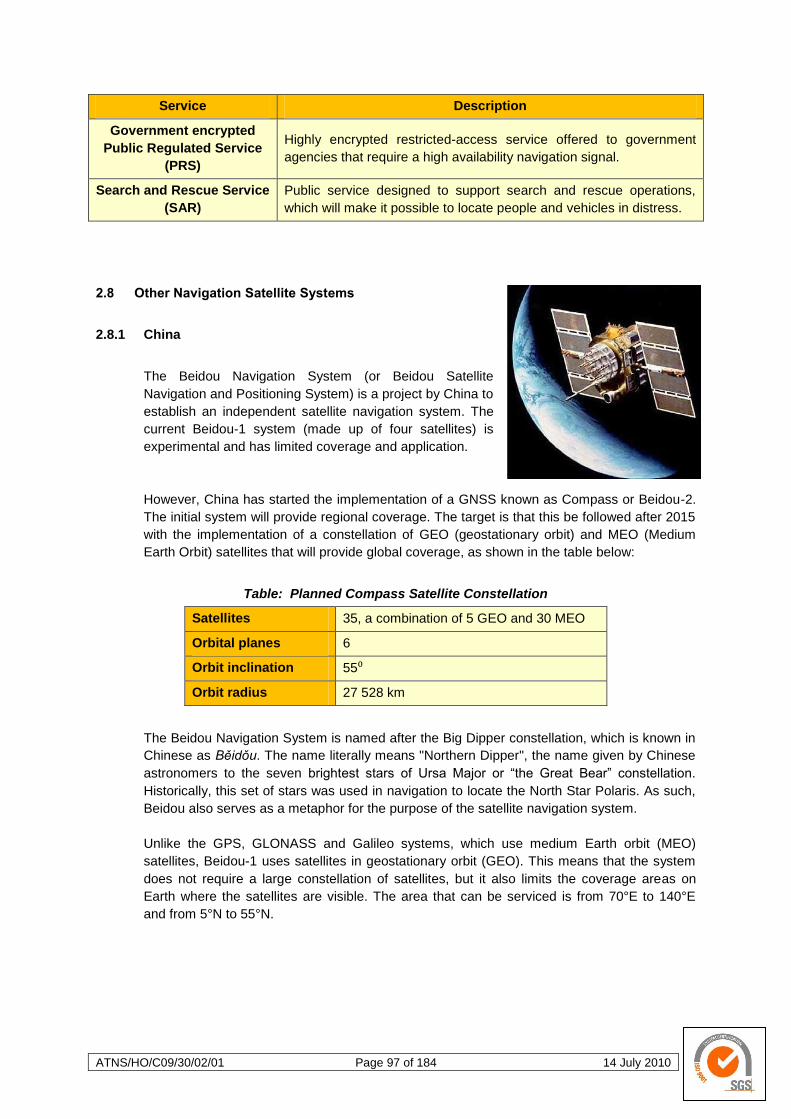
ATNS/HO/C09/30/02/01 Page 97 of 184 14 July 2010
Service Description
Government encrypted
Public Regulated Service
(PRS)
Highly encrypted restricted-access service offered to government
agencies that require a high availability navigation signal.
Search and Rescue Service
(SAR)
Public service designed to support search and rescue operations,
which will make it possible to locate people and vehicles in distress.
2.8 Other Navigation Satellite Systems
2.8.1 China
The Beidou Navigation System (or Beidou Satellite
Navigation and Positioning System) is a project by China to
establish an independent satellite navigation system. The
current Beidou-1 system (made up of four satellites) is
experimental and has limited coverage and application.
However, China has started the implementation of a GNSS known as Compass or Beidou-2.
The initial system will provide regional coverage. The target is that this be followed after 2015
with the implementation of a constellation of GEO (geostationary orbit) and MEO (Medium
Earth Orbit) satellites that will provide global coverage, as shown in the table below:
Table: Planned Compass Satellite Constellation
Satellites 35, a combination of 5 GEO and 30 MEO
Orbital planes 6
Orbit inclination 55⁰
Orbit radius 27 528 km
The Beidou Navigation System is named after the Big Dipper constellation, which is known in
Chinese as Běidǒu. The name literally means "Northern Dipper", the name given by Chinese
astronomers to the seven brightest stars of Ursa Major or ―the Great Bear‖ constellation.
Historically, this set of stars was used in navigation to locate the North Star Polaris. As such,
Beidou also serves as a metaphor for the purpose of the satellite navigation system.
Unlike the GPS, GLONASS and Galileo systems, which use medium Earth orbit (MEO)
satellites, Beidou-1 uses satellites in geostationary orbit (GEO). This means that the system
does not require a large constellation of satellites, but it also limits the coverage areas on
Earth where the satellites are visible. The area that can be serviced is from 70°E to 140°E
and from 5°N to 55°N.

ATNS/HO/C09/30/02/01 Page 98 of 184 14 July 2010
Coverage Polygon of Beidou-1
As mentioned above, the Beidou-1 satellites (1A, 1B, 1C and 1D), were designed as
experimental satellites. The new system (Compass or Beidou-2) will be a constellation of 35
satellites, which include five geostationary orbit satellites, for backward compatibility with
Beidou-1, and 30 medium Earth orbit satellites, that will offer complete coverage of the globe.
There will be two levels of service provided; free service for those in China, and licensed
service for the military:
The free service will have a 10-metre location-tracking accuracy, will synchronise clocks
with an accuracy of 50 ns, and measure speeds within 0.2 m/s.
The licensed service will be more accurate than the free service, can be used for
communication, and will supply information about the status to the users.
Three satellites for Compass have been launched in 2007, 2009 and also early in 2010. In the
next few years, China plans to continue setting up the system for global operation from 2017
with 30 satellites. Regional operation within Asia Pacific would be completed with more than
10 satellites in late 2012.
Table: Beidou-1 and Compass Satellites
Date Launcher Satellite Orbit Usable
31/10/2000 LM-3A Beidou-1A GEO 140°E Unclear
21/12/2000 LM-3A Beidou-1B GEO 80°E Unclear
25/05/2003 LM-3A Beidou-1C GEO 110.5°E Unclear
03/02/2007 LM-3A Beidou-1D De-orbited No
14/04/2007 LM-3A Compass-M1 MEO 21 500 km Yes
15/04/2009 LM-3C Compass-G2 GEO drifting No
17/01/2010 LM-3C Compass-G1 GEO 144.5°E Yes
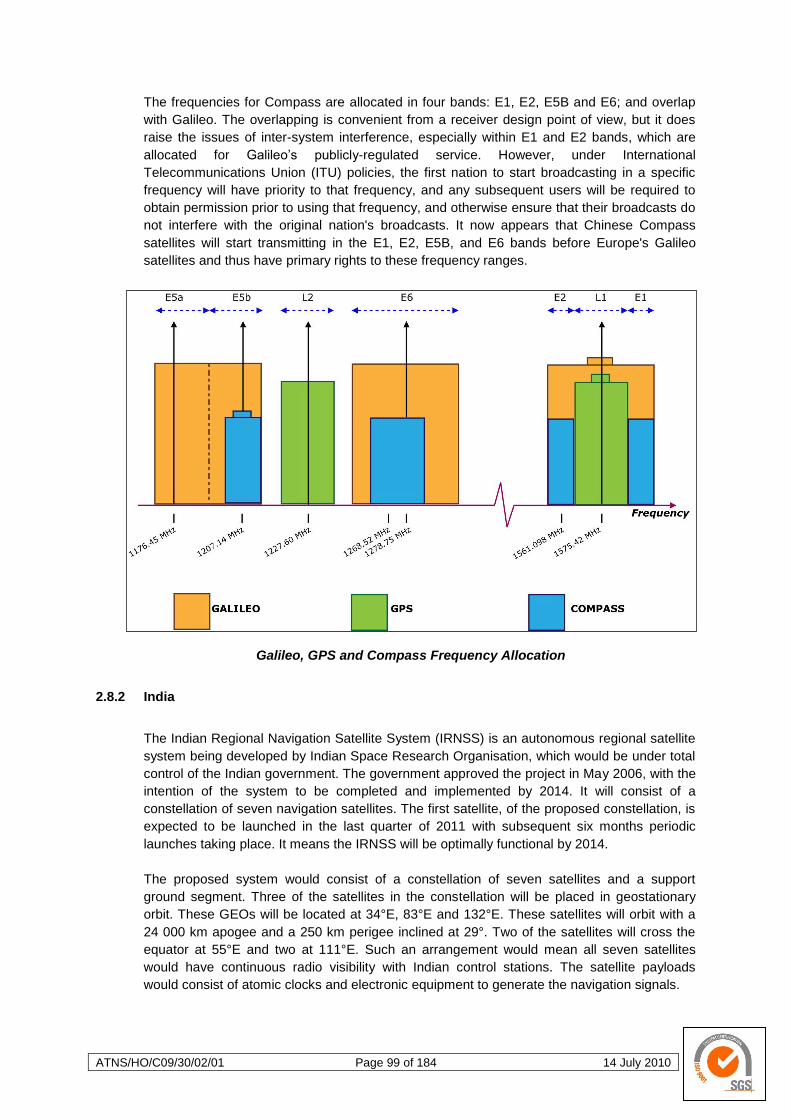
ATNS/HO/C09/30/02/01 Page 99 of 184 14 July 2010
The frequencies for Compass are allocated in four bands: E1, E2, E5B and E6; and overlap
with Galileo. The overlapping is convenient from a receiver design point of view, but it does
raise the issues of inter-system interference, especially within E1 and E2 bands, which are
allocated for Galileo‘s publicly-regulated service. However, under International
Telecommunications Union (ITU) policies, the first nation to start broadcasting in a specific
frequency will have priority to that frequency, and any subsequent users will be required to
obtain permission prior to using that frequency, and otherwise ensure that their broadcasts do
not interfere with the original nation's broadcasts. It now appears that Chinese Compass
satellites will start transmitting in the E1, E2, E5B, and E6 bands before Europe's Galileo
satellites and thus have primary rights to these frequency ranges.
Galileo, GPS and Compass Frequency Allocation
2.8.2 India
The Indian Regional Navigation Satellite System (IRNSS) is an autonomous regional satellite
system being developed by Indian Space Research Organisation, which would be under total
control of the Indian government. The government approved the project in May 2006, with the
intention of the system to be completed and implemented by 2014. It will consist of a
constellation of seven navigation satellites. The first satellite, of the proposed constellation, is
expected to be launched in the last quarter of 2011 with subsequent six months periodic
launches taking place. It means the IRNSS will be optimally functional by 2014.
The proposed system would consist of a constellation of seven satellites and a support
ground segment. Three of the satellites in the constellation will be placed in geostationary
orbit. These GEOs will be located at 34°E, 83°E and 132°E. These satellites will orbit with a
24 000 km apogee and a 250 km perigee inclined at 29°. Two of the satellites will cross the
equator at 55°E and two at 111°E. Such an arrangement would mean all seven satellites
would have continuous radio visibility with Indian control stations. The satellite payloads
would consist of atomic clocks and electronic equipment to generate the navigation signals.
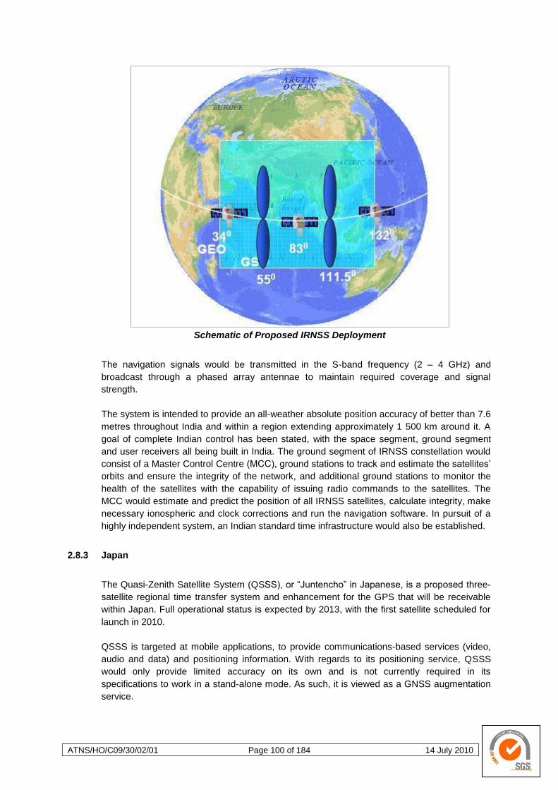
ATNS/HO/C09/30/02/01 Page 100 of 184 14 July 2010
Schematic of Proposed IRNSS Deployment
The navigation signals would be transmitted in the S-band frequency (2 – 4 GHz) and
broadcast through a phased array antennae to maintain required coverage and signal
strength.
The system is intended to provide an all-weather absolute position accuracy of better than 7.6
metres throughout India and within a region extending approximately 1 500 km around it. A
goal of complete Indian control has been stated, with the space segment, ground segment
and user receivers all being built in India. The ground segment of IRNSS constellation would
consist of a Master Control Centre (MCC), ground stations to track and estimate the satellites‘
orbits and ensure the integrity of the network, and additional ground stations to monitor the
health of the satellites with the capability of issuing radio commands to the satellites. The
MCC would estimate and predict the position of all IRNSS satellites, calculate integrity, make
necessary ionospheric and clock corrections and run the navigation software. In pursuit of a
highly independent system, an Indian standard time infrastructure would also be established.
2.8.3 Japan
The Quasi-Zenith Satellite System (QSSS), or ―Juntencho‖ in Japanese, is a proposed three-
satellite regional time transfer system and enhancement for the GPS that will be receivable
within Japan. Full operational status is expected by 2013, with the first satellite scheduled for
launch in 2010.
QSSS is targeted at mobile applications, to provide communications-based services (video,
audio and data) and positioning information. With regards to its positioning service, QSSS
would only provide limited accuracy on its own and is not currently required in its
specifications to work in a stand-alone mode. As such, it is viewed as a GNSS augmentation
service.
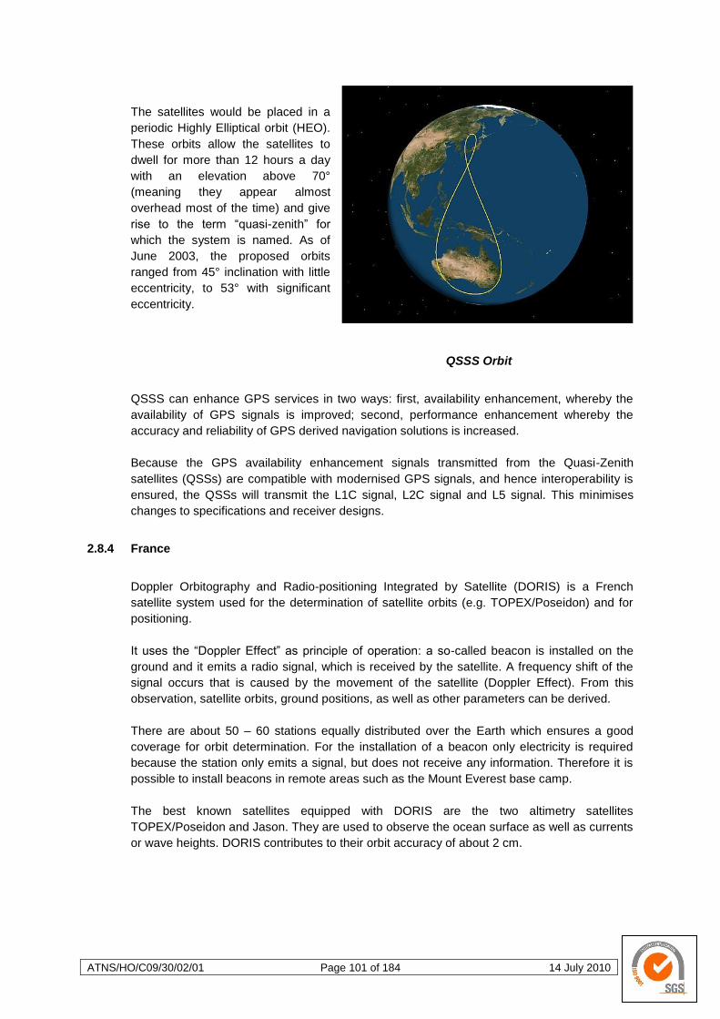
ATNS/HO/C09/30/02/01 Page 101 of 184 14 July 2010
The satellites would be placed in a
periodic Highly Elliptical orbit (HEO).
These orbits allow the satellites to
dwell for more than 12 hours a day
with an elevation above 70°
(meaning they appear almost
overhead most of the time) and give
rise to the term ―quasi-zenith‖ for
which the system is named. As of
June 2003, the proposed orbits
ranged from 45° inclination with little
eccentricity, to 53° with significant
eccentricity.
QSSS Orbit
QSSS can enhance GPS services in two ways: first, availability enhancement, whereby the
availability of GPS signals is improved; second, performance enhancement whereby the
accuracy and reliability of GPS derived navigation solutions is increased.
Because the GPS availability enhancement signals transmitted from the Quasi-Zenith
satellites (QSSs) are compatible with modernised GPS signals, and hence interoperability is
ensured, the QSSs will transmit the L1C signal, L2C signal and L5 signal. This minimises
changes to specifications and receiver designs.
2.8.4 France
Doppler Orbitography and Radio-positioning Integrated by Satellite (DORIS) is a French
satellite system used for the determination of satellite orbits (e.g. TOPEX/Poseidon) and for
positioning.
It uses the ―Doppler Effect‖ as principle of operation: a so-called beacon is installed on the
ground and it emits a radio signal, which is received by the satellite. A frequency shift of the
signal occurs that is caused by the movement of the satellite (Doppler Effect). From this
observation, satellite orbits, ground positions, as well as other parameters can be derived.
There are about 50 – 60 stations equally distributed over the Earth which ensures a good
coverage for orbit determination. For the installation of a beacon only electricity is required
because the station only emits a signal, but does not receive any information. Therefore it is
possible to install beacons in remote areas such as the Mount Everest base camp.
The best known satellites equipped with DORIS are the two altimetry satellites
TOPEX/Poseidon and Jason. They are used to observe the ocean surface as well as currents
or wave heights. DORIS contributes to their orbit accuracy of about 2 cm.
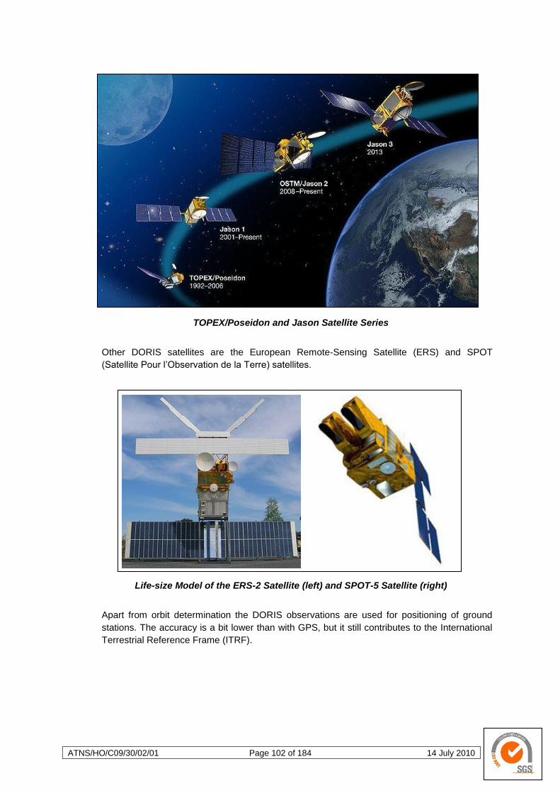
ATNS/HO/C09/30/02/01 Page 102 of 184 14 July 2010
TOPEX/Poseidon and Jason Satellite Series
Other DORIS satellites are the European Remote-Sensing Satellite (ERS) and SPOT
(Satellite Pour l‘Observation de la Terre) satellites.
Life-size Model of the ERS-2 Satellite (left) and SPOT-5 Satellite (right)
Apart from orbit determination the DORIS observations are used for positioning of ground
stations. The accuracy is a bit lower than with GPS, but it still contributes to the International
Terrestrial Reference Frame (ITRF).

ATNS/HO/C09/30/02/01 Page 103 of 184 14 July 2010
3 ALL WEATHER OPERATION
All weather operations refers to the practice of instrument flying (IF) and the associated procedures as
applied during flight under instrument flight rules (IFR). An instrument approach or instrument
approach procedure (IAP) is a type of air navigation that allows a pilot to fly an aircraft to a position
from which a landing may be effected under reduced visibility conditions (known as instrument
meteorological conditions or IMC), or to reach visual conditions permitting a visual approach and
subsequent landing. IAPs fall into one of two categories. Firstly and also the more commonly used is
the pilot interpreted approach procedure (ILS, VOR and NDB approaches). Secondly and used
infrequently by civilian commercial operators is the ATC interpreted approach procedure (surveillance
radar approach – SRA, ground controlled approach – GCA and the oldest of them all the VDF cloud
brake procedures). Pilot interpreted approaches are classified as either precision or non-precision,
depending on the accuracy and capabilities of the navigational aids (NAVAIDs) used. Precision
approaches utilise both lateral (localiser) and vertical (glide slope) information. Non-precision
approaches provide lateral course information only.
The publications depicting instrument approach procedures are called Terminal Procedures, but are
commonly referred to by pilots as "approach plates". These documents graphically depict the specific
procedure to be followed by a pilot for a particular type of approach to a given runway. They depict
prescribed altitudes and headings to be flown, as well as obstacles, terrain, and potentially conflicting
airspace. In addition, they also list missed approach procedures and commonly-used radio
frequencies.
Instrument approaches are generally designed such that a pilot of an aircraft in instrument
meteorological conditions (IMC), by the means of radio, GNSS or INS navigation with no assistance
from air traffic control, can navigate to the airport, hold in the vicinity of the airport if required, then fly
to a position from where sufficient visual reference of the runway may be established to allow landing
to be made, or execute a missed approach if the required visual contact with the aerodrome and/or
runway periphery is not established. The whole of the approach is defined and published in this way
so that instrument approaches may be completed procedurally at airports where air traffic control
does not use radar or in the case of radar failure.
Instrument approaches generally involve five phases of flight:
Arrival: where the pilot navigates to the
Initial Approach Fix (IAF: a NAVAID or
reporting point), and where holding can
take place.
Initial Approach: the phase of flight after
the IAF, where the pilot commences the
navigation of the aircraft to the Final
Approach Fix (FAF), a position aligned
with the runway, from where a safe
controlled descent back towards the
airport can be initiated.
Intermediate Approach: an additional
phase in more complex approaches that
may be required to navigate to the FAF.
Final approach: between 4 and 12 NMs of straight flight descending at a set rate (usually an angle
of between 2.5 and 6⁰).
Missed Approach: an optional phase; should the required visual reference for landing not have
been obtained at the end of the final approach, this allows the pilot to climb the aircraft to a safe
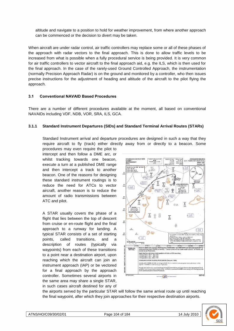
ATNS/HO/C09/30/02/01 Page 104 of 184 14 July 2010
altitude and navigate to a position to hold for weather improvement, from where another approach
can be commenced or the decision to divert may be taken.
When aircraft are under radar control, air traffic controllers may replace some or all of these phases of
the approach with radar vectors to the final approach. This is done to allow traffic levels to be
increased from what is possible when a fully procedural service is being provided. It is very common
for air traffic controllers to vector aircraft to the final approach aid, e.g. the ILS, which is then used for
the final approach. In the case of the rarely-used Ground Controlled Approach, the instrumentation
(normally Precision Approach Radar) is on the ground and monitored by a controller, who then issues
precise instructions for the adjustment of heading and altitude of the aircraft to the pilot flying the
approach.
3.1 Conventional NAVAID Based Procedures
There are a number of different procedures available at the moment, all based on conventional
NAVAIDs including VDF, NDB, VOR, SRA, ILS, GCA.
3.1.1 Standard Instrument Departures (SIDs) and Standard Terminal Arrival Routes (STARs)
Standard Instrument arrival and departure procedures are designed in such a way that they
require aircraft to fly (track) either directly away from or directly to a beacon. Some
procedures may even require the pilot to
intercept and then follow a DME arc, or
whilst tracking towards one beacon,
execute a turn at a published DME range
and then intercept a track to another
beacon. One of the reasons for designing
these standard instrument routings is to
reduce the need for ATCs to vector
aircraft, another reason is to reduce the
amount of radio transmissions between
ATC and pilot.
A STAR usually covers the phase of a
flight that lies between the top of descent
from cruise or en-route flight and the final
approach to a runway for landing. A
typical STAR consists of a set of starting
points, called transitions, and a
description of routes (typically via
waypoints) from each of these transitions
to a point near a destination airport, upon
reaching which the aircraft can join an
instrument approach (IAP) or be vectored
for a final approach by the approach
controller. Sometimes several airports in
the same area may share a single STAR,
in such cases aircraft destined for any of
the airports served by the particular STAR will follow the same arrival route up until reaching
the final waypoint, after which they join approaches for their respective destination airports.
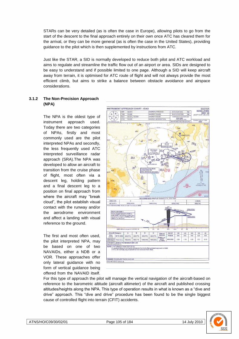
ATNS/HO/C09/30/02/01 Page 105 of 184 14 July 2010
STARs can be very detailed (as is often the case in Europe), allowing pilots to go from the
start of the descent to the final approach entirely on their own once ATC has cleared them for
the arrival, or they can be more general (as is often the case in the United States), providing
guidance to the pilot which is then supplemented by instructions from ATC.
Just like the STAR, a SID is normally developed to reduce both pilot and ATC workload and
aims to regulate and streamline the traffic flow out of an airport or area. SIDs are designed to
be easy to understand and if possible limited to one page. Although a SID will keep aircraft
away from terrain, it is optimised for ATC route of flight and will not always provide the most
efficient climb, but aims to strike a balance between obstacle avoidance and airspace
considerations.
3.1.2 The Non-Precision Approach
(NPA)
The NPA is the oldest type of
instrument approach used.
Today there are two categories
of NPAs, firstly and most
commonly used are the pilot
interpreted NPAs and secondly,
the less frequently used ATC
interpreted surveillance radar
approach (SRA).The NPA was
developed to allow an aircraft to
transition from the cruise phase
of flight, most often via a
descent leg, holding pattern
and a final descent leg to a
position on final approach from
where the aircraft may ―break
cloud‖, the pilot establish visual
contact with the runway and/or
the aerodrome environment
and affect a landing with visual
reference to the ground.
The first and most often used,
the pilot interpreted NPA, may
be based on one of two
NAVAIDs, either a NDB or a
VOR. These approaches offer
only lateral guidance with no
form of vertical guidance being
offered from the NAVAID itself.
For this type of approach the pilot will manage the vertical navigation of the aircraft-based on
reference to the barometric altitude (aircraft altimeter) of the aircraft and published crossing
altitudes/heights along the NPA. This type of operation results in what is known as a ―dive and
drive‖ approach. This ―dive and drive‖ procedure has been found to be the single biggest
cause of controlled flight into terrain (CFIT) accidents.
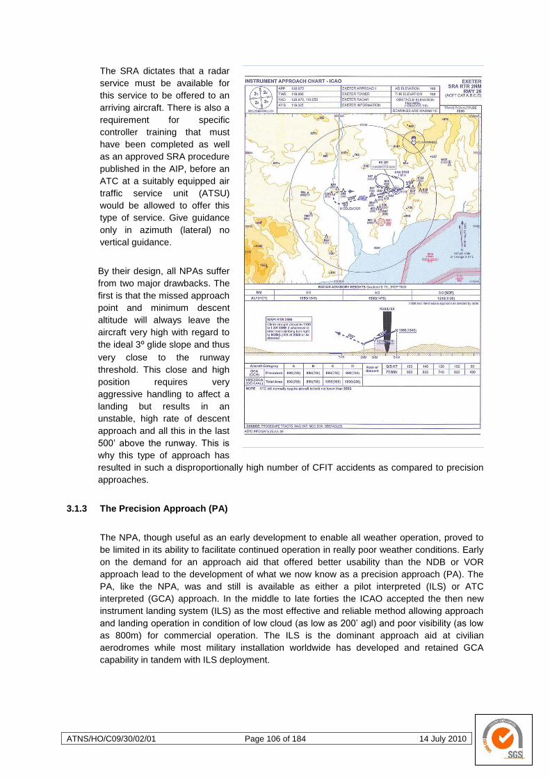
ATNS/HO/C09/30/02/01 Page 106 of 184 14 July 2010
The SRA dictates that a radar
service must be available for
this service to be offered to an
arriving aircraft. There is also a
requirement for specific
controller training that must
have been completed as well
as an approved SRA procedure
published in the AIP, before an
ATC at a suitably equipped air
traffic service unit (ATSU)
would be allowed to offer this
type of service. Give guidance
only in azimuth (lateral) no
vertical guidance.
By their design, all NPAs suffer
from two major drawbacks. The
first is that the missed approach
point and minimum descent
altitude will always leave the
aircraft very high with regard to
the ideal 3⁰ glide slope and thus
very close to the runway
threshold. This close and high
position requires very
aggressive handling to affect a
landing but results in an
unstable, high rate of descent
approach and all this in the last
500‘ above the runway. This is
why this type of approach has
resulted in such a disproportionally high number of CFIT accidents as compared to precision
approaches.
3.1.3 The Precision Approach (PA)
The NPA, though useful as an early development to enable all weather operation, proved to
be limited in its ability to facilitate continued operation in really poor weather conditions. Early
on the demand for an approach aid that offered better usability than the NDB or VOR
approach lead to the development of what we now know as a precision approach (PA). The
PA, like the NPA, was and still is available as either a pilot interpreted (ILS) or ATC
interpreted (GCA) approach. In the middle to late forties the ICAO accepted the then new
instrument landing system (ILS) as the most effective and reliable method allowing approach
and landing operation in condition of low cloud (as low as 200‘ agl) and poor visibility (as low
as 800m) for commercial operation. The ILS is the dominant approach aid at civilian
aerodromes while most military installation worldwide has developed and retained GCA
capability in tandem with ILS deployment.
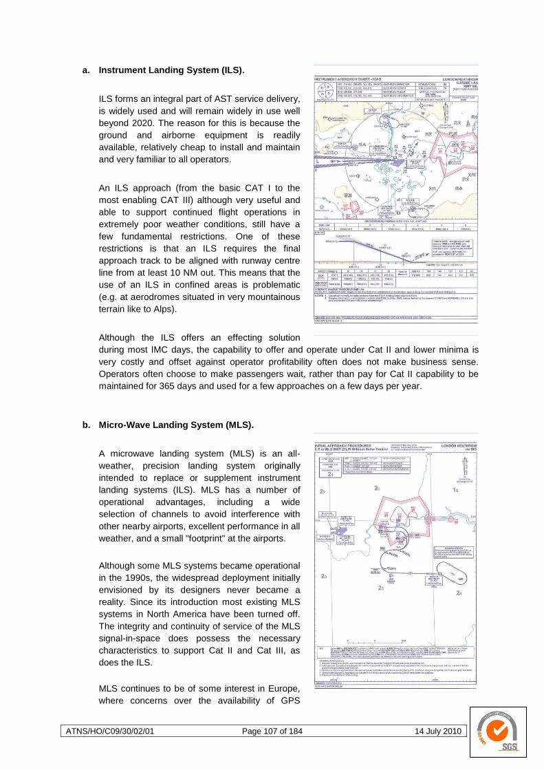
ATNS/HO/C09/30/02/01 Page 107 of 184 14 July 2010
a. Instrument Landing System (ILS).
ILS forms an integral part of AST service delivery,
is widely used and will remain widely in use well
beyond 2020. The reason for this is because the
ground and airborne equipment is readily
available, relatively cheap to install and maintain
and very familiar to all operators.
An ILS approach (from the basic CAT I to the
most enabling CAT III) although very useful and
able to support continued flight operations in
extremely poor weather conditions, still have a
few fundamental restrictions. One of these
restrictions is that an ILS requires the final
approach track to be aligned with runway centre
line from at least 10 NM out. This means that the
use of an ILS in confined areas is problematic
(e.g. at aerodromes situated in very mountainous
terrain like to Alps).
Although the ILS offers an effecting solution
during most IMC days, the capability to offer and operate under Cat II and lower minima is
very costly and offset against operator profitability often does not make business sense.
Operators often choose to make passengers wait, rather than pay for Cat II capability to be
maintained for 365 days and used for a few approaches on a few days per year.
b. Micro-Wave Landing System (MLS).
A microwave landing system (MLS) is an all-
weather, precision landing system originally
intended to replace or supplement instrument
landing systems (ILS). MLS has a number of
operational advantages, including a wide
selection of channels to avoid interference with
other nearby airports, excellent performance in all
weather, and a small "footprint" at the airports.
Although some MLS systems became operational
in the 1990s, the widespread deployment initially
envisioned by its designers never became a
reality. Since its introduction most existing MLS
systems in North America have been turned off.
The integrity and continuity of service of the MLS
signal-in-space does possess the necessary
characteristics to support Cat II and Cat III, as
does the ILS.
MLS continues to be of some interest in Europe,
where concerns over the availability of GPS
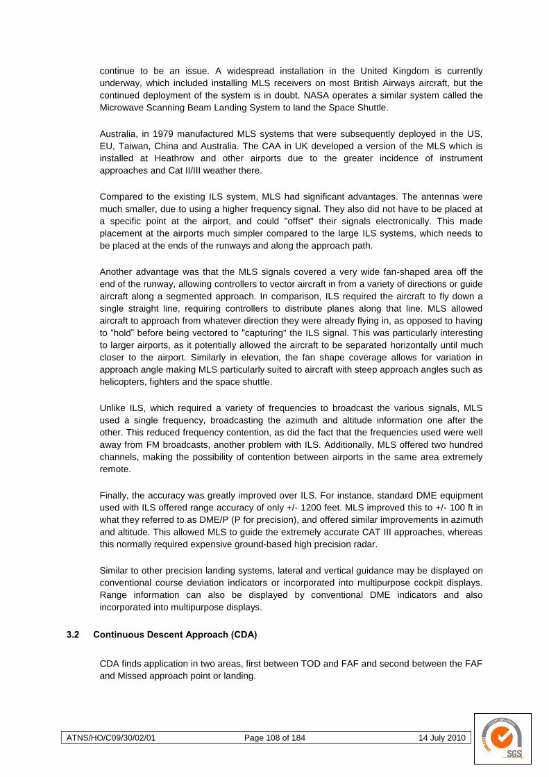
ATNS/HO/C09/30/02/01 Page 108 of 184 14 July 2010
continue to be an issue. A widespread installation in the United Kingdom is currently
underway, which included installing MLS receivers on most British Airways aircraft, but the
continued deployment of the system is in doubt. NASA operates a similar system called the
Microwave Scanning Beam Landing System to land the Space Shuttle.
Australia, in 1979 manufactured MLS systems that were subsequently deployed in the US,
EU, Taiwan, China and Australia. The CAA in UK developed a version of the MLS which is
installed at Heathrow and other airports due to the greater incidence of instrument
approaches and Cat II/III weather there.
Compared to the existing ILS system, MLS had significant advantages. The antennas were
much smaller, due to using a higher frequency signal. They also did not have to be placed at
a specific point at the airport, and could "offset" their signals electronically. This made
placement at the airports much simpler compared to the large ILS systems, which needs to
be placed at the ends of the runways and along the approach path.
Another advantage was that the MLS signals covered a very wide fan-shaped area off the
end of the runway, allowing controllers to vector aircraft in from a variety of directions or guide
aircraft along a segmented approach. In comparison, ILS required the aircraft to fly down a
single straight line, requiring controllers to distribute planes along that line. MLS allowed
aircraft to approach from whatever direction they were already flying in, as opposed to having
to ―hold‖ before being vectored to "capturing" the ILS signal. This was particularly interesting
to larger airports, as it potentially allowed the aircraft to be separated horizontally until much
closer to the airport. Similarly in elevation, the fan shape coverage allows for variation in
approach angle making MLS particularly suited to aircraft with steep approach angles such as
helicopters, fighters and the space shuttle.
Unlike ILS, which required a variety of frequencies to broadcast the various signals, MLS
used a single frequency, broadcasting the azimuth and altitude information one after the
other. This reduced frequency contention, as did the fact that the frequencies used were well
away from FM broadcasts, another problem with ILS. Additionally, MLS offered two hundred
channels, making the possibility of contention between airports in the same area extremely
remote.
Finally, the accuracy was greatly improved over ILS. For instance, standard DME equipment
used with ILS offered range accuracy of only +/- 1200 feet. MLS improved this to +/- 100 ft in
what they referred to as DME/P (P for precision), and offered similar improvements in azimuth
and altitude. This allowed MLS to guide the extremely accurate CAT III approaches, whereas
this normally required expensive ground-based high precision radar.
Similar to other precision landing systems, lateral and vertical guidance may be displayed on
conventional course deviation indicators or incorporated into multipurpose cockpit displays.
Range information can also be displayed by conventional DME indicators and also
incorporated into multipurpose displays.
3.2 Continuous Descent Approach (CDA)
CDA finds application in two areas, first between TOD and FAF and second between the FAF
and Missed approach point or landing.
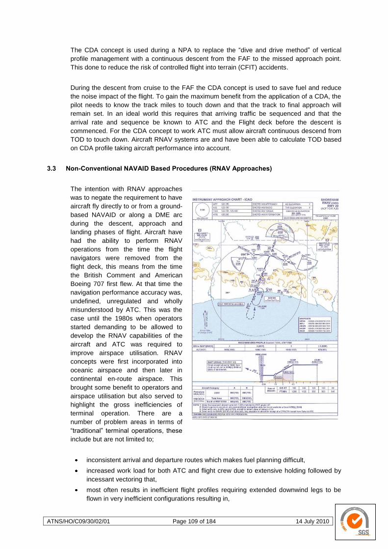
ATNS/HO/C09/30/02/01 Page 109 of 184 14 July 2010
The CDA concept is used during a NPA to replace the ―dive and drive method‖ of vertical
profile management with a continuous descent from the FAF to the missed approach point.
This done to reduce the risk of controlled flight into terrain (CFIT) accidents.
During the descent from cruise to the FAF the CDA concept is used to save fuel and reduce
the noise impact of the flight. To gain the maximum benefit from the application of a CDA, the
pilot needs to know the track miles to touch down and that the track to final approach will
remain set. In an ideal world this requires that arriving traffic be sequenced and that the
arrival rate and sequence be known to ATC and the Flight deck before the descent is
commenced. For the CDA concept to work ATC must allow aircraft continuous descend from
TOD to touch down. Aircraft RNAV systems are and have been able to calculate TOD based
on CDA profile taking aircraft performance into account.
3.3 Non-Conventional NAVAID Based Procedures (RNAV Approaches)
The intention with RNAV approaches
was to negate the requirement to have
aircraft fly directly to or from a ground-
based NAVAID or along a DME arc
during the descent, approach and
landing phases of flight. Aircraft have
had the ability to perform RNAV
operations from the time the flight
navigators were removed from the
flight deck, this means from the time
the British Comment and American
Boeing 707 first flew. At that time the
navigation performance accuracy was,
undefined, unregulated and wholly
misunderstood by ATC. This was the
case until the 1980s when operators
started demanding to be allowed to
develop the RNAV capabilities of the
aircraft and ATC was required to
improve airspace utilisation. RNAV
concepts were first incorporated into
oceanic airspace and then later in
continental en-route airspace. This
brought some benefit to operators and
airspace utilisation but also served to
highlight the gross inefficiencies of
terminal operation. There are a
number of problem areas in terms of
―traditional‖ terminal operations, these
include but are not limited to;
inconsistent arrival and departure routes which makes fuel planning difficult,
increased work load for both ATC and flight crew due to extensive holding followed by
incessant vectoring that,
most often results in inefficient flight profiles requiring extended downwind legs to be
flown in very inefficient configurations resulting in,

ATNS/HO/C09/30/02/01 Page 110 of 184 14 July 2010
high fuel burns,
extensive noise and environmental pollution and
adding to airspace congestion.
3.3.1 Overlay Procedures Concept
Early attempts to improve terminal operations resulted in ―overlay‖ RNAV procedures being
developed that would initially ―shadow‖ conventional terminal procedures. These overlay
RNAV procedures brought no benefit or improvement to the situation and appeared to be a
waste of time and effort. The reason why no benefit was gained from this was because these
new procedures differed from the conventional procedures only in as much as the definition of
the waypoints was changed from using conventional ground-based beacons to using ―RNAV
waypoints‖. The drive to develop and implement these overlay RNAV procedures had a few
fundamental flaws that meant these overlay procedures would never be able to realise the
anticipated benefits. To ultimately realise the expected benefits from terminal RNAV
procedures the terminal operational concept needed to change completely. The RNAV
operation itself needed to be clearly regulated to ensure accuracy, integrity and continuity, the
airspace concept needed to clearly define the navigation specification and the ATM system
needed to be redefined to allow for and effectively incorporate automated flow management
capabilities. One of the fundamental RNAV capabilities that was never employed effectively
was the required time of arrival (RTA) capability. The RTA capability combined with the ability
of the RNAV system to calculate TOD based on the CDA concept means that the flight deck
system is now and has been able for a long time to calculate the most efficient descend
profile while being able to fly any published RNAV STAR.
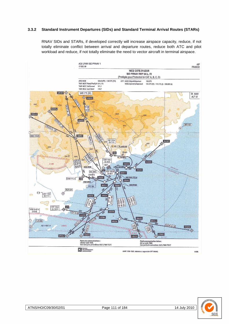
ATNS/HO/C09/30/02/01 Page 111 of 184 14 July 2010
3.3.2 Standard Instrument Departures (SIDs) and Standard Terminal Arrival Routes (STARs)
RNAV SIDs and STARs, if developed correctly will increase airspace capacity, reduce, if not
totally eliminate conflict between arrival and departure routes, reduce both ATC and pilot
workload and reduce, if not totally eliminate the need to vector aircraft in terminal airspace.
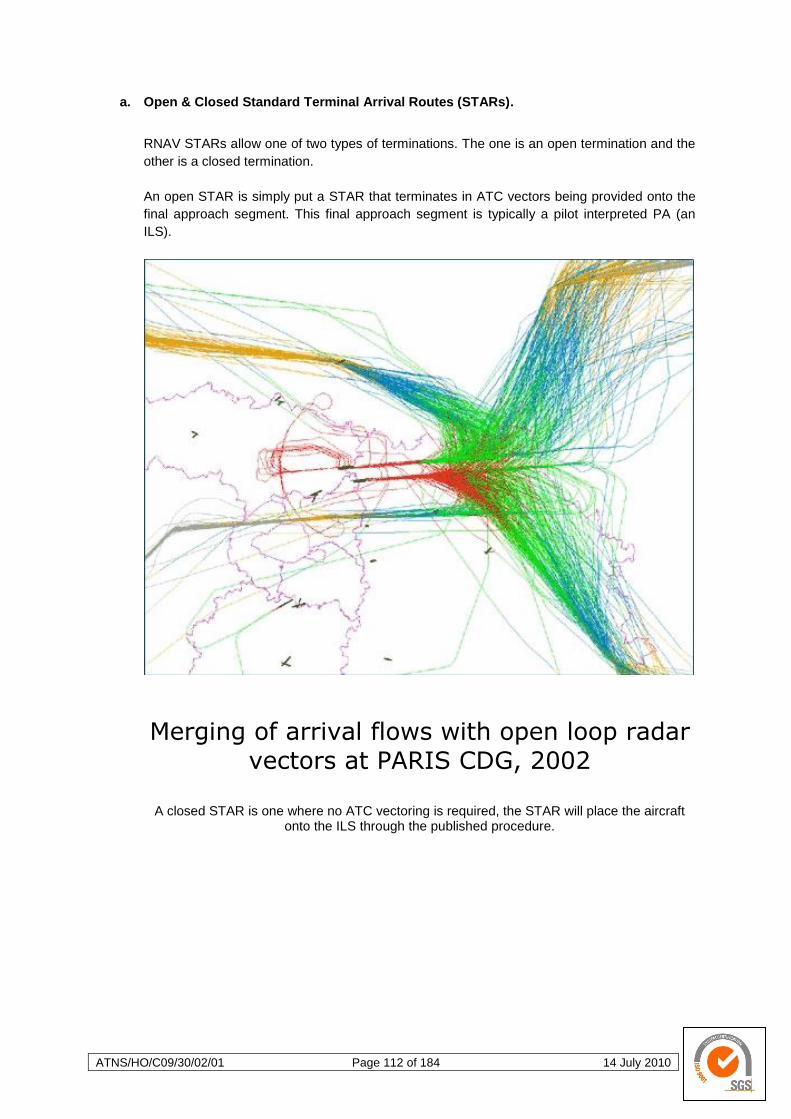
ATNS/HO/C09/30/02/01 Page 112 of 184 14 July 2010
a. Open & Closed Standard Terminal Arrival Routes (STARs).
RNAV STARs allow one of two types of terminations. The one is an open termination and the
other is a closed termination.
An open STAR is simply put a STAR that terminates in ATC vectors being provided onto the
final approach segment. This final approach segment is typically a pilot interpreted PA (an
ILS).
Merging of arrival flows with open loop radar vectors at PARIS CDG, 2002
A closed STAR is one where no ATC vectoring is required, the STAR will place the aircraft
onto the ILS through the published procedure.
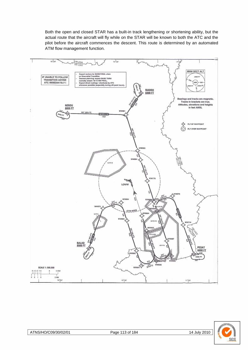
ATNS/HO/C09/30/02/01 Page 113 of 184 14 July 2010
Both the open and closed STAR has a built-in track lengthening or shortening ability, but the
actual route that the aircraft will fly while on the STAR will be known to both the ATC and the
pilot before the aircraft commences the descent. This route is determined by an automated
ATM flow management function.
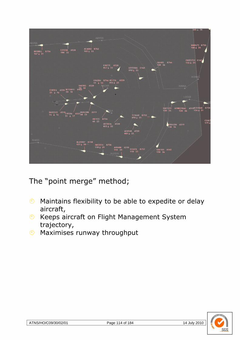
ATNS/HO/C09/30/02/01 Page 114 of 184 14 July 2010
The “point merge” method;
Maintains flexibility to be able to expedite or delay
aircraft,
Keeps aircraft on Flight Management System
trajectory,
Maximises runway throughput

ATNS/HO/C09/30/02/01 Page 115 of 184 14 July 2010
3.3.3 Sensor Specific Area Navigation (RNAV) Procedures
a. RNAV 5 (in Europe referred to and applied as Basic-RNAV aka B-RNAV).
B-RNAV requires aircraft conformance to a track keeping accuracy of ± 5 NM for at least 95%
of flight time to ensure that the capacity gains are achieved whilst meeting the required safety
targets. B-RNAV can be achieved using inputs from VOR/DME, DME/DME or GPS. (INS may
be used for up to 2 hours after the last radio beacon or on-ground update. B-RNAV
requirements became mandatory in ECAC airspace on 23 April 1998 on the entire ATS route
network above FL 95. B-RNAV is already being used on selected routes into and out of
terminal airspace in some States.
i. What is B-RNAV?
RNAV is a method of navigation which permits aircraft operations on any desired flight path
within the coverage of station referenced navigation aids or within the limits of the capability of
self-contained aids, or a combination of these. Airborne RNAV equipment automatically
determines aircraft position by processing data from one or more sensors and guides the
aircraft in accordance with appropriate routing instructions. Position can be displayed to the
pilot in various ways, most practically in terms of the aircraft position relative to the pre-
computed desired track. Most RNAV equipment can employ any lateral displacement of the
aircraft from the desired track to generate track guidance signals to the auto-pilot. With other
less sophisticated RNAV equipment manual corrective action is taken by the pilot.
B(asic)-RNAV defines European RNAV operations which satisfy a required track keeping
accuracy of ± 5 NM for at least 95% of the flight time. This level of navigation accuracy is
comparable with that which can be achieved by conventional navigation techniques on ATC
routes defined by VOR/DME, when VORs are less than 100 NM apart. For the determination
of aircraft position suitable input data can be derived from the following navigation sources:
DME/DME
VOR/DME (within 62 NM VOR range)
INS (with radio beacon updating or limited to 2 hours use after last on-ground position
update)
LORAN C (with use limitations)
GPS (with use limitations)
For ECAC airspace the primary sources of navigation information are VOR/DME, DME/DME
and GPS. The availability and continuity of VOR and DME coverage have been calculated for
most of Europe and they are considered to be capable of meeting the requirements of the en-
route phase of operations.
ATNS/HO/C09/30/02/01 Page 116 of 184 14 July 2010
ii. What does B-RNAV offer?
B-RNAV operations in ECAC airspace provides a number of advantages over the
conventional ground-based navigation, whilst maintaining existing safety standards. These
advantages and their related benefits include:
(1) improved management in the flow of traffic by repositioning of intersections;
(2) more efficient use of available airspace, by means of a more flexible ATS route
structure and the application of the Flexible Use of Airspace (FUA) Concept,
permitting the establishment of:
more direct routes (dual or parallel) to accommodate a greater flow of en-route
traffic;
bypass routes for aircraft overflying high-density terminal areas;
alternative or contingency routes on either a planned or an ad hoc basis;
establishment of optimum locations for holding patterns;
optimised feeder routes;
(3) reduction in flight distances resulting in fuel savings;
(4) reduction in the number of ground navigation facilities.
All these are easily achievable. One of the main objectives of the initial application of RNAV
should be to ensure that full use is made of the existing on board RNAV systems. Many
RNAV systems have been fitted for some time and are capable of performance better than
RNP 5 accuracy. Simulations demonstrated that capacity gains up to 30% could be achieved
only by a uniform application of B-RNAV, in parallel with the revised ATS route network and
the implementation of FUA concept.
iii. Where and how could B-RNAV be implemented?
If implemented in terminal airspace the requirement will be that VOR/DME remains available
for reversionary navigation. VOR/DME must also remain available for reversionary navigation
on ATS routes in the lower airspace.
iv. Where has B-RNAV been implemented?
B-RNAV has been implemented throughout the entire ATS Route Network in the ECAC area
since 23 April 1998. B-RNAV applies to all IFR flights operating in the public transport
category, in conformity with the ICAO procedures. In some cases B-RNAV has also been
implemented on certain SIDs and STARs provided that:
(1) The B-RNAV portion of the route is above Minimum Sector Altitude/Minimum Flight
Altitude/Minimum Radar Vectoring Altitude (as appropriate), has been developed in
accordance with established PANS-OPS criteria for en-route operations and
conforms to B-RNAV en-route design principles.
(2) The initial portion of departure procedures is non-RNAV up to a conventional fix
beyond which the B-RNAV procedure is provided in accordance with the criteria
given above.
(3) The B-RNAV portion of an arrival route terminates at a conventional fix in
accordance with the criteria given above and the arrival is completed by an
alternative final approach procedure (most often the conventional ILS), also
appropriately approved.

ATNS/HO/C09/30/02/01 Page 117 of 184 14 July 2010
(4) Due regard has been taken, during the design process, of the users operating
procedures. The National Authorities may designate domestic routes in the lower
airspace, which can be used by aircraft which are not B-RNAV capable. Each State
should publish appropriate mandatory carriage requirements identifying the airspace
within which the mandate prevails. National Administrations are required to publish
the coverage of their navigation aids, to notify the status of these aids and to ensure
that the co-ordinates of all aids and waypoints are referenced to the WGS-84
geodetic reference system. Manufacturers, operators and database providers are
responsible for ensuring that RNAV systems operate in accordance with the WGS-84
system. The specific procedures for B-RNAV operations are incorporated in the
ICAO Doc 7030/4 Ed. 1997.
b. Lateral Navigation (LNAV).
LNAV refers to navigating over a ground
track with guidance from an electronic
device which gives the pilot (or autopilot)
error indications in the lateral direction
only and not in the vertical direction. In
aviation lateral navigation is of two
guidance types: linear guidance and
angular guidance. Linear means that the
left and right deviations of the aircraft are
available as a distance of the aircraft from
the desired ground track to its actual
position on either side of the desired track.
In angular guidance, the error indication is given in degrees of angle from the desired line
relative to a ground-based navigation device. To provide an illustration, as the aircraft
approaches the ground device with a constant angular error, its distance to the desired
ground line decreases. In the context of aviation instrument approaches, an LNAV approach
(one that uses lateral navigation) is implied to be a GNSS navigation signal based approach
and to have linear lateral guidance. A VOR based approach will have angular lateral
guidance.
The approach minimas for
LNAV approaches are higher
than that of ILS approaches
and higher than those for
RNAV approaches that
incorporate vertical
guidance. An aircraft
executing an LNAV
instrument approach must
descend incrementally rather
than follow a fixed glide
slope. A LNAV approach is a
type of 'non-precision'
approach. In a precision
approach there is electronic
vertical (slope) guidance down to a decision altitude (DA). In the case of the non-precision
approach, the aircraft can descend only to the minimum descent altitude or MDA. An MDA
segment is flown until the airport is in sight and the pilot can land. If the airport is not in sight
ATNS/HO/C09/30/02/01 Page 118 of 184 14 July 2010
by the time the pilot reaches a missed approach point (MAP) on the MDA, a missed approach
must be initiated.
The RNAV implementation of the non-precision LNAV approach (using GNSS as navigation
signal source) may only be flown if satellite configuration at the time of the approach will
support the accuracy requirement that will allow a full scale course deviation indication of 0.3
nautical miles (about 1800 feet to the left and right or 3600 feet total) from the final approach
fix and extending uninterrupted through to the missed approach point. If this sensitivity is not
available or is lost, the pilot will be notified by the on-board receiver (via RAIM checking) and
must initiate a missed approach or continue with an alternate type of approach using an
alternate navigation reference (typically conventional NAVAIDs).
c. Barometric Vertical Navigation (Baro-VNAV) and Approach with Vertical Guidance
(APV).
VNAV in aviation is a function of autopilot which directs vertical movement of aircraft either
according to a pre-programmed FMS flight plan during cruise or according to ILS glide slope
during an approach. Vertical guidance is given with reference to barometric altitude.
VNAV in the sense that the FMS directs altitude according to a flight plan was first introduced
on B757 and B767 in 1982, while Autoland (using ILS guidance) has been available since
mid-20th century. In the USA Localiser performance with vertical guidance (LPV) are the
highest precision GPS (WAAS enabled) instrument approach procedures currently available
without specialised aircrew training requirements, such as required navigation performance
(RNP). Landing minima are similar to those in an instrument landing system (ILS), that is, a
decision altitude of 200 feet and visibility of 1/2 mile. Examples in the USA (from Garmin) are
the GNS 480, GNS 430W, 530W, and the Garmin G1000. LPV is designed to provide 16
meter horizontal accuracy and 20 meter vertical accuracy 95 percent of the time. Actual
performance has exceeded these levels. WAAS has never been observed to have a vertical
error greater than 12 meters in its operational history.
As of January 15, 2009 the Federal Aviation Administration has published 1,445 LPV
approaches at 793 airports. This is greater than the number of published Category I ILS
procedures.
3.3.4 RNP Procedures (Pre-PBN)
a. Baro-VNAV and APV.
The baro-VNAV navigation system presents the pilot with estimated vertical guidance
referenced to a specified vertical path angle (VPA), nominally of 3º. The computed vertical
guide is based on the barometric altitude and is specified as a VPA from the reference datum
height (RDH). The calculated vertical path is stored in RNAV/RNP system navigation data
base as part of the instrument flight procedure specification. For other flight phases,
barometric VNAV offers vertical guidance path information that can be defined by vertical
angles or altitudes at the procedure fixes. It should be noted that vertical navigation can be
performed without VNAV guidance in the initial and intermediate segments of an instrument
procedure. It is anticipated that aircraft authorised to conduct RNP authorisation required

ATNS/HO/C09/30/02/01 Page 119 of 184 14 July 2010
GN
SS
Lan
din
g S
yste
m
approach (RNP AR APCH) operations would also be considered eligible for the baro-VNAV
operations
NAVAID infrastructure. The procedure design does not have unique infrastructure
requirements. This criterion is based upon the use of barometric altimetry by an airborne
RNAV/RNP system whose performance capability supports the required operation. The
procedure design will have to take into account the functional capabilities required as
prescribed by the ICAO.
b. GNSS Landing System (GLS).
The aviation industry has been developing
a positioning and landing system based
on a GNSS. These efforts culminated in
late 2001, when the ICAO approved an
international standard for a landing system
based on RNAV using local correction of
GNSS data to a level that would support
instrument approaches. This work by the
ICAO resulted in the ICAO Standards and
Recommended Practices (SARPS) that
define the characteristics of a GBAS. The
GBAS service provides a correction signal
that can be used by suitably equipped
aircraft as the basis of a GNSS landing
system (GLS). The initial SARPS by the
ICAO supports an approach service. Future refinements should lead to full low-visibility
service (i.e., takeoff, approach, and landing) and low visibility taxi operations.
i. Elements of the GLS
The GLS consists of three major elements;
a GNSS that supports worldwide navigation position fixing,
a GBAS facility at each equipped airport that provides local navigation satellite
correction signals, and
avionics in each aircraft that process and provide guidance and control based on the
satellite and GBAS signals (fig.1).
The GLS uses a GNSS for the basic positioning service. The GPS constellation already is in
place and improvements are planned over the coming decades. The Galileo constellation was
scheduled to be available in 2008, but is not yet fully operational.
A GBAS service is used for local augmentation of the basic GNSS positioning at or near the
relevant airport via a GBAS radio transmitter facility. The GBAS corrections are transmitted
from a ground station and can be received by nearby aircraft via a VHF Data Broadcast
(VDB) data link.
As far as the development of avionics is concerned, Boeing aircraft that are currently being
produced contain Multi-Mode Receivers (MMR) that supports conventional ILS and basic
GPS operations. For the GLS application the aircraft systems only use satellite information
that is supported by correction data received from the GBAS. When the aircraft are relatively
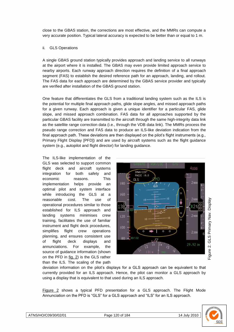
ATNS/HO/C09/30/02/01 Page 120 of 184 14 July 2010
Fig
ure
2. G
LS
Prim
ary
Nav. D
isp
lay
close to the GBAS station, the corrections are most effective, and the MMRs can compute a
very accurate position. Typical lateral accuracy is expected to be better than or equal to 1 m.
ii. GLS Operations
A single GBAS ground station typically provides approach and landing service to all runways
at the airport where it is installed. The GBAS may even provide limited approach service to
nearby airports. Each runway approach direction requires the definition of a final approach
segment (FAS) to establish the desired reference path for an approach, landing, and rollout.
The FAS data for each approach are determined by the GBAS service provider and typically
are verified after installation of the GBAS ground station.
One feature that differentiates the GLS from a traditional landing system such as the ILS is
the potential for multiple final approach paths, glide slope angles, and missed approach paths
for a given runway. Each approach is given a unique identifier for a particular FAS, glide
slope, and missed approach combination. FAS data for all approaches supported by the
particular GBAS facility are transmitted to the aircraft through the same high-integrity data link
as the satellite range correction data (i.e., through the VDB data link). The MMRs process the
pseudo range correction and FAS data to produce an ILS-like deviation indication from the
final approach path. These deviations are then displayed on the pilot‘s flight instruments (e.g.,
Primary Flight Display [PFD]) and are used by aircraft systems such as the flight guidance
system (e.g., autopilot and flight director) for landing guidance.
The ILS-like implementation of the
GLS was selected to support common
flight deck and aircraft systems
integration for both safety and
economic reasons. This
implementation helps provide an
optimal pilot and system interface
while introducing the GLS at a
reasonable cost. The use of
operational procedures similar to those
established for ILS approach and
landing systems minimises crew
training, facilitates the use of familiar
instrument and flight deck procedures,
simplifies flight crew operations
planning, and ensures consistent use
of flight deck displays and
annunciations. For example, the
source of guidance information (shown
on the PFD in fig. 2) is the GLS rather
than the ILS. The scaling of the path
deviation information on the pilot‘s displays for a GLS approach can be equivalent to that
currently provided for an ILS approach. Hence, the pilot can monitor a GLS approach by
using a display that is equivalent to that used during an ILS approach.
Figure 2 shows a typical PFD presentation for a GLS approach. The Flight Mode
Annunciation on the PFD is ―GLS‖ for a GLS approach and ―ILS‖ for an ILS approach.
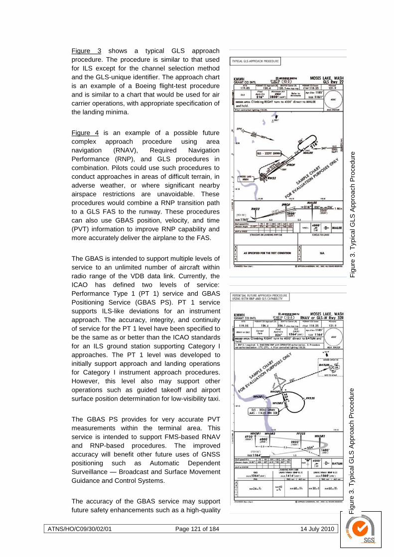
ATNS/HO/C09/30/02/01 Page 121 of 184 14 July 2010
Fig
ure
3. T
ypic
al G
LS
Appro
ach P
rocedure
F
igure
3. T
ypic
al G
LS
Appro
ach P
rocedure
Figure 3 shows a typical GLS approach
procedure. The procedure is similar to that used
for ILS except for the channel selection method
and the GLS-unique identifier. The approach chart
is an example of a Boeing flight-test procedure
and is similar to a chart that would be used for air
carrier operations, with appropriate specification of
the landing minima.
Figure 4 is an example of a possible future
complex approach procedure using area
navigation (RNAV), Required Navigation
Performance (RNP), and GLS procedures in
combination. Pilots could use such procedures to
conduct approaches in areas of difficult terrain, in
adverse weather, or where significant nearby
airspace restrictions are unavoidable. These
procedures would combine a RNP transition path
to a GLS FAS to the runway. These procedures
can also use GBAS position, velocity, and time
(PVT) information to improve RNP capability and
more accurately deliver the airplane to the FAS.
The GBAS is intended to support multiple levels of
service to an unlimited number of aircraft within
radio range of the VDB data link. Currently, the
ICAO has defined two levels of service:
Performance Type 1 (PT 1) service and GBAS
Positioning Service (GBAS PS). PT 1 service
supports ILS-like deviations for an instrument
approach. The accuracy, integrity, and continuity
of service for the PT 1 level have been specified to
be the same as or better than the ICAO standards
for an ILS ground station supporting Category I
approaches. The PT 1 level was developed to
initially support approach and landing operations
for Category I instrument approach procedures.
However, this level also may support other
operations such as guided takeoff and airport
surface position determination for low-visibility taxi.
The GBAS PS provides for very accurate PVT
measurements within the terminal area. This
service is intended to support FMS-based RNAV
and RNP-based procedures. The improved
accuracy will benefit other future uses of GNSS
positioning such as Automatic Dependent
Surveillance — Broadcast and Surface Movement
Guidance and Control Systems.
The accuracy of the GBAS service may support
future safety enhancements such as a high-quality
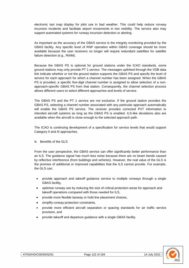
ATNS/HO/C09/30/02/01 Page 122 of 184 14 July 2010
electronic taxi map display for pilot use in bad weather. This could help reduce runway
incursion incidents and facilitate airport movements in low visibility. The service also may
support automated systems for runway incursion detection or alerting.
As important as the accuracy of the GBAS service is the integrity monitoring provided by the
GBAS facility. Any specific level of RNP operation within GBAS coverage should be more
available because the user receivers no longer will require redundant satellites for satellite
failure detection (e.g., RAIM).
Because the GBAS PS is optional for ground stations under the ICAO standards, some
ground stations may only provide PT 1 service. The messages uplinked through the VDB data
link indicate whether or not the ground station supports the GBAS PS and specify the level of
service for each approach for which a channel number has been assigned. When the GBAS
PS is provided, a specific five-digit channel number is assigned to allow selection of a non-
approach-specific GBAS PS from that station. Consequently, the channel selection process
allows different users to select different approaches and levels of service.
The GBAS PS and the PT 1 service are not exclusive. If the ground station provides the
GBAS PS, selecting a channel number associated with any particular approach automatically
will enable the GBAS PS service. The receiver provides corrected PVT information to
intended aircraft systems as long as the GBAS PS is enabled. ILS-like deviations also are
available when the aircraft is close enough to the selected approach path.
The ICAO is continuing development of a specification for service levels that would support
Category II and III approaches.
iii. Benefits of the GLS
From the user perspective, the GBAS service can offer significantly better performance than
an ILS. The guidance signal has much less noise because there are no beam bends caused
by reflective interference (from buildings and vehicles). However, the real value of the GLS is
the promise of additional or improved capabilities that the ILS cannot provide. For example,
the GLS can;
provide approach and takeoff guidance service to multiple runways through a single
GBAS facility,
optimise runway use by reducing the size of critical protection areas for approach and
takeoff operations compared with those needed for ILS,
provide more flexible taxiway or hold line placement choices,
simplify runway protection constraints,
provide more efficient aircraft separation or spacing standards for air traffic service
provision, and
provide takeoff and departure guidance with a single GBAS facility.
ATNS/HO/C09/30/02/01 Page 123 of 184 14 July 2010
From the service provider perspective, the GBAS can potentially provide several significant
advantages over the ILS.
First, significant cost savings may be realised because a single system may be able to
support all runways at an airport.
Operational constraints often occur with the ILS when an Air Traffic Service provider
needs to switch a commonly used ILS frequency to serve a different runway direction.
This is not an issue with the GBAS because ample channels are available for
assignment to each approach. In addition, because the GBAS serves all runway ends
with a single VHF frequency, the limited navigation frequency spectrum is used much
more efficiently. In fact, a GBAS may even be able to support a significant level of
instrument approach and departure operations at other nearby airports.
The placement of GBAS ground stations is considerably simpler than for the ILS
because GBAS service accuracy is not degraded by any radio frequency propagation
effects in the VHF band. Unlike the ILS, which requires level ground and clear areas on
the runway, the siting of a GBAS VHF transmitter can be more flexible than ILS. GBAS
receivers do not need to be placed near a runway in a specific geometry, as is the case
with the ILS or MLS. Hence, this virtually eliminates the requirements for critical
protection areas or restricted areas to protect against signal interference on runways
and nearby taxiways.
Finally, the GBAS should have less frequent and less costly flight inspection
requirements than the ILS because the role of flight inspection for GBAS is different.
Traditional flight inspection, if needed at all, primarily would apply only during the initial
installation and ground station commissioning. This flight inspection would verify the
suitability of the various approach path (FAS) definitions and ensure that the GBAS-to-
runway geometry definitions are correct. Because verifying the coverage of the VDB
data link principally is a continuity of service issue rather than an accuracy or integrity
issue, it typically would not require periodic inspection.
GBAS systems capable of supporting Category II and III operations internationally are
envisioned. Airborne system elements that would be necessary for the enhanced GLS
capability (e.g., MMR and GLS automatic landing provisions) already are well on the way to
certification or operational authorisation. Airborne systems and flight deck displays eventually
will evolve to take full advantage of the linear characteristic of the GLS over the angular
aspects of the ILS.
iv. GLS Operations in the US
Flight-test and operational experience with the GLS has been excellent. Many GLS-guided
approaches and landings have been conducted successfully at a variety of airports and under
various runway conditions.
Both automatic landings and landings using head-up displays have been accomplished safely
through landing rollout, in both routine and non-normal conditions.
On the pilot‘s flight displays, the GLS has been unusually steady and smooth when compared
with the current ILS systems even when critical areas necessary for the ILS approaches were
unprotected during the GLS approaches.
ATNS/HO/C09/30/02/01 Page 124 of 184 14 July 2010
4 THE PERFORMANCE BASED NAVIGATION CONCEPT
4.1 Description of Performance Based Navigation
4.1.1 Introduction
The continuing growth of aviation places increased demands on airspace capacity thereby
emphasising the need for optimum utilisation of available airspace. Improved operational efficiency
derived from the application of area navigation (RNAV) has resulted in the development of different
RNAV applications in various regions of the world and for all phases of flight. These airborne
applications could potentially be expanded to provide guidance for ground movement operations.
RNAV systems evolved in a manner similar to air routes and procedures based on conventional
ground-based NAVAIDS. Historically a specific RNAV system would be identified and its performance
would then be evaluated through a combination of analysis and flight testing. For domestic
operations, the initial RNAV systems used VOR and DME as navigation signal source to calculate
position, for oceanic operations various types of inertial navigation systems (INS) were employed.
These ―new‖ systems were each developed, evaluated and certified separately. Airspace and
obstacle clearance criteria were developed based on the performance of the available equipment. In
some cases, the individual model and make of equipment that could be operated within the airspace
concerned was specifically identified. Such prescriptive requirements resulted in delays to the
introduction of new RNAV system capabilities and higher costs for maintaining appropriate
certification. To avoid such prescriptive requirements, the ICAO developed an alternative method for
defining equipage requirements by specifying the performance requirements. This is termed
Performance-Based Navigation (PBN).
Requirements for navigation applications on specific routes or within a specific airspace must be
defined and regulated in a clear and concise manner by the appropriate authority. This will enable
compliance by air operators with specific airspace requirements, including navigation specifications
that must be developed to allow the maximum benefit possible by the wide spread application of
RNAV procedures.
a. General.
The PBN concept specifies that aircraft RNAV system performance requirements be defined
in terms of accuracy, integrity, availability, continuity and functionality required for the
proposed operations in the context of a particular airspace concept, when supported by the
appropriate navigation infrastructure. The PBN concept represents a shift from sensor-based
to Performance-Based Navigation. Performance requirements are identified in navigation
specifications, which also identify the choice of navigation sensors and equipment that may
be used to meet the performance requirements. The ICAO defined navigation specifications
provide specific implementation guidance for States and operators in order to facilitate global
harmonization.
The PBN concept suggests that during PBN implementation the first step would be to define
and then publish generic navigation requirements based on specific operational requirements.
Operators then evaluate equipment options in respect of available technology and navigation
infrastructure. The operator is thus free to select the most cost-effective option in terms of
equipment to meet the published requirements for operation in a particular airspace.
Technology can evolve over time without requiring published procedures to be revisited,
provided that the required navigation performance is provided by the RNAV system (or RNP
system).
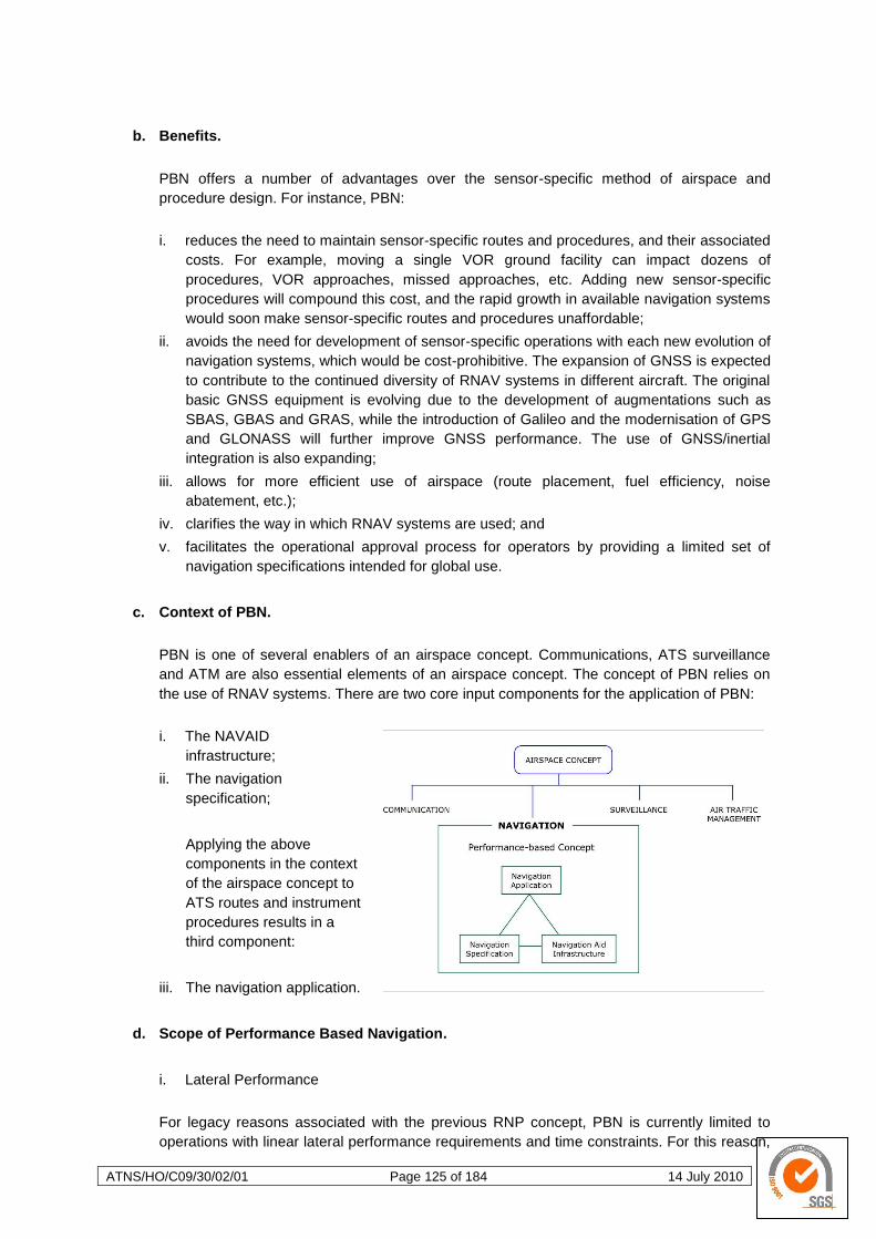
ATNS/HO/C09/30/02/01 Page 125 of 184 14 July 2010
b. Benefits.
PBN offers a number of advantages over the sensor-specific method of airspace and
procedure design. For instance, PBN:
i. reduces the need to maintain sensor-specific routes and procedures, and their associated
costs. For example, moving a single VOR ground facility can impact dozens of
procedures, VOR approaches, missed approaches, etc. Adding new sensor-specific
procedures will compound this cost, and the rapid growth in available navigation systems
would soon make sensor-specific routes and procedures unaffordable;
ii. avoids the need for development of sensor-specific operations with each new evolution of
navigation systems, which would be cost-prohibitive. The expansion of GNSS is expected
to contribute to the continued diversity of RNAV systems in different aircraft. The original
basic GNSS equipment is evolving due to the development of augmentations such as
SBAS, GBAS and GRAS, while the introduction of Galileo and the modernisation of GPS
and GLONASS will further improve GNSS performance. The use of GNSS/inertial
integration is also expanding;
iii. allows for more efficient use of airspace (route placement, fuel efficiency, noise
abatement, etc.);
iv. clarifies the way in which RNAV systems are used; and
v. facilitates the operational approval process for operators by providing a limited set of
navigation specifications intended for global use.
c. Context of PBN.
PBN is one of several enablers of an airspace concept. Communications, ATS surveillance
and ATM are also essential elements of an airspace concept. The concept of PBN relies on
the use of RNAV systems. There are two core input components for the application of PBN:
i. The NAVAID
infrastructure;
ii. The navigation
specification;
Applying the above
components in the context
of the airspace concept to
ATS routes and instrument
procedures results in a
third component:
iii. The navigation application.
d. Scope of Performance Based Navigation.
i. Lateral Performance
For legacy reasons associated with the previous RNP concept, PBN is currently limited to
operations with linear lateral performance requirements and time constraints. For this reason,
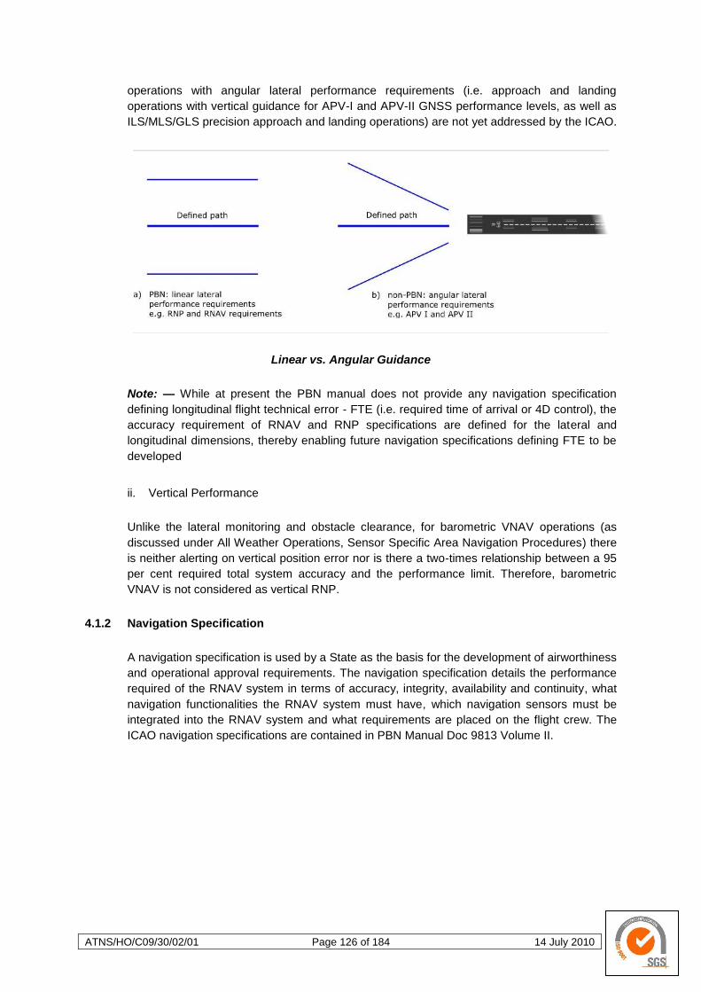
ATNS/HO/C09/30/02/01 Page 126 of 184 14 July 2010
operations with angular lateral performance requirements (i.e. approach and landing
operations with vertical guidance for APV-I and APV-II GNSS performance levels, as well as
ILS/MLS/GLS precision approach and landing operations) are not yet addressed by the ICAO.
Linear vs. Angular Guidance
Note: — While at present the PBN manual does not provide any navigation specification
defining longitudinal flight technical error - FTE (i.e. required time of arrival or 4D control), the
accuracy requirement of RNAV and RNP specifications are defined for the lateral and
longitudinal dimensions, thereby enabling future navigation specifications defining FTE to be
developed
ii. Vertical Performance
Unlike the lateral monitoring and obstacle clearance, for barometric VNAV operations (as
discussed under All Weather Operations, Sensor Specific Area Navigation Procedures) there
is neither alerting on vertical position error nor is there a two-times relationship between a 95
per cent required total system accuracy and the performance limit. Therefore, barometric
VNAV is not considered as vertical RNP.
4.1.2 Navigation Specification
A navigation specification is used by a State as the basis for the development of airworthiness
and operational approval requirements. The navigation specification details the performance
required of the RNAV system in terms of accuracy, integrity, availability and continuity, what
navigation functionalities the RNAV system must have, which navigation sensors must be
integrated into the RNAV system and what requirements are placed on the flight crew. The
ICAO navigation specifications are contained in PBN Manual Doc 9813 Volume II.
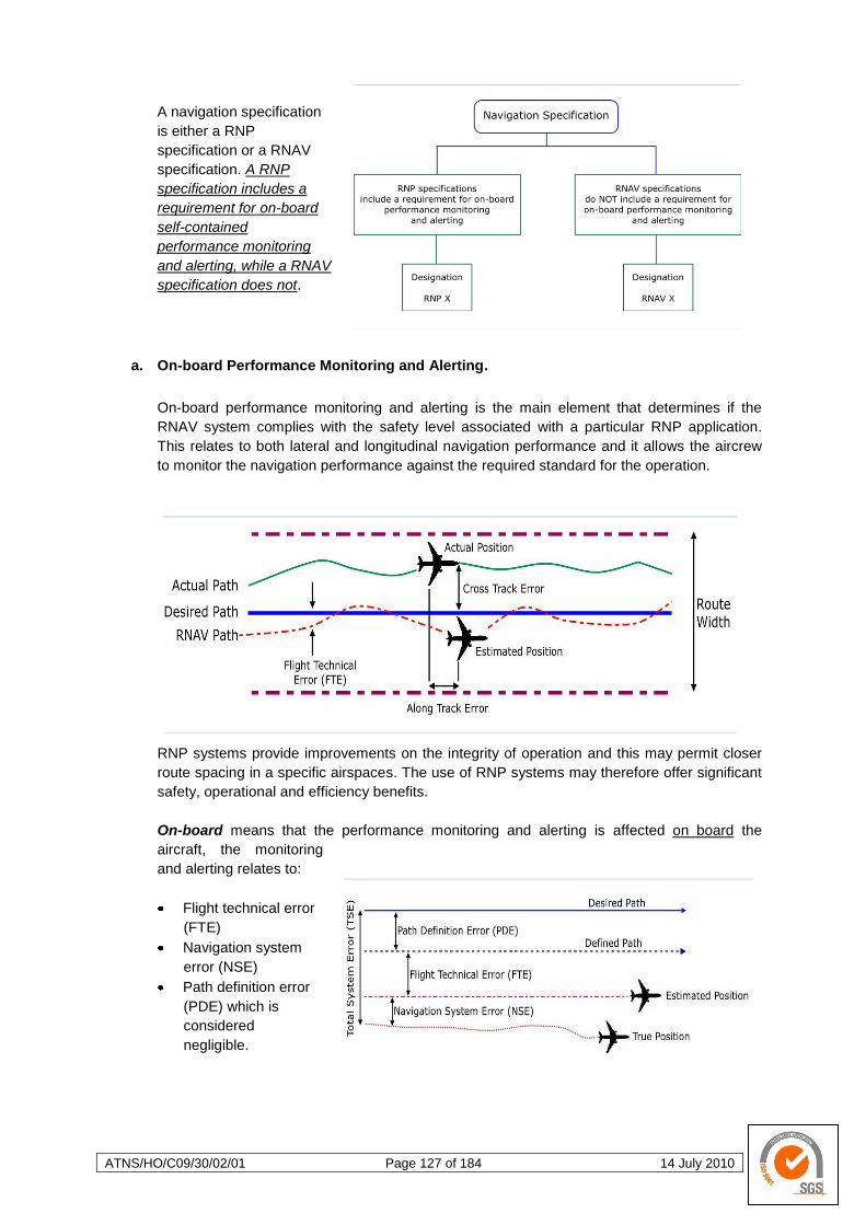
ATNS/HO/C09/30/02/01 Page 127 of 184 14 July 2010
A navigation specification
is either a RNP
specification or a RNAV
specification. A RNP
specification includes a
requirement for on-board
self-contained
performance monitoring
and alerting, while a RNAV
specification does not.
a. On-board Performance Monitoring and Alerting.
On-board performance monitoring and alerting is the main element that determines if the
RNAV system complies with the safety level associated with a particular RNP application.
This relates to both lateral and longitudinal navigation performance and it allows the aircrew
to monitor the navigation performance against the required standard for the operation.
RNP systems provide improvements on the integrity of operation and this may permit closer
route spacing in a specific airspaces. The use of RNP systems may therefore offer significant
safety, operational and efficiency benefits.
On-board means that the performance monitoring and alerting is affected on board the
aircraft, the monitoring
and alerting relates to:
Flight technical error
(FTE)
Navigation system
error (NSE)
Path definition error
(PDE) which is
considered
negligible.
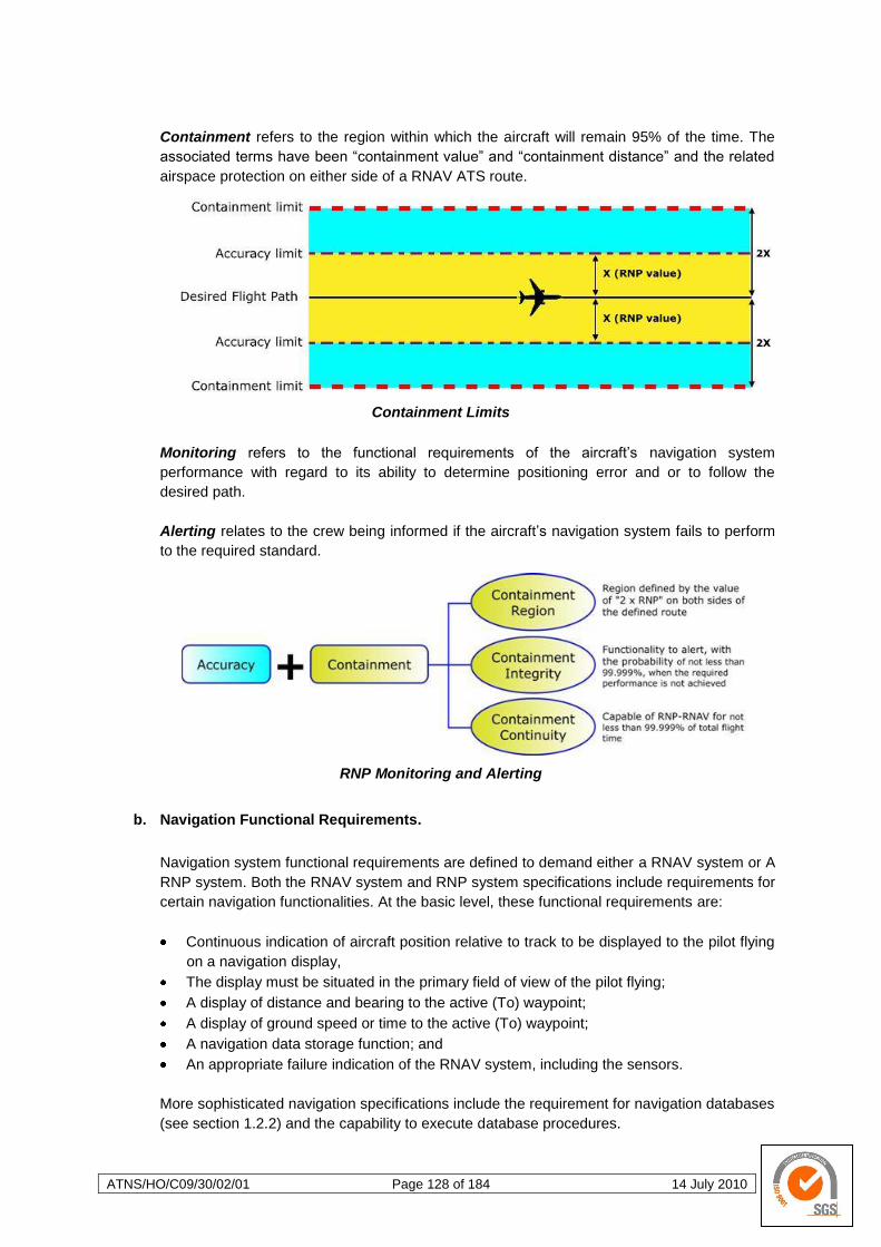
ATNS/HO/C09/30/02/01 Page 128 of 184 14 July 2010
Containment refers to the region within which the aircraft will remain 95% of the time. The
associated terms have been ―containment value‖ and ―containment distance‖ and the related
airspace protection on either side of a RNAV ATS route.
Containment Limits
Monitoring refers to the functional requirements of the aircraft‘s navigation system
performance with regard to its ability to determine positioning error and or to follow the
desired path.
Alerting relates to the crew being informed if the aircraft‘s navigation system fails to perform
to the required standard.
RNP Monitoring and Alerting
b. Navigation Functional Requirements.
Navigation system functional requirements are defined to demand either a RNAV system or A
RNP system. Both the RNAV system and RNP system specifications include requirements for
certain navigation functionalities. At the basic level, these functional requirements are:
Continuous indication of aircraft position relative to track to be displayed to the pilot flying
on a navigation display,
The display must be situated in the primary field of view of the pilot flying;
A display of distance and bearing to the active (To) waypoint;
A display of ground speed or time to the active (To) waypoint;
A navigation data storage function; and
An appropriate failure indication of the RNAV system, including the sensors.
More sophisticated navigation specifications include the requirement for navigation databases
(see section 1.2.2) and the capability to execute database procedures.
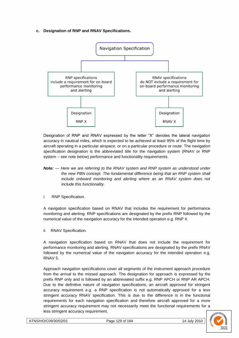
ATNS/HO/C09/30/02/01 Page 129 of 184 14 July 2010
c. Designation of RNP and RNAV Specifications.
Designation of RNP and RNAV expressed by the letter ―X‖ denotes the lateral navigation
accuracy in nautical miles, which is expected to be achieved at least 95% of the flight time by
aircraft operating in a particular airspace, or on a particular procedure or route. The navigation
specification designation is the abbreviated title for the navigation system (RNAV or RNP
system – see note below) performance and functionality requirements.
Note: — Here we are referring to the RNAV system and RNP system as understood under
the new PBN concept. The fundamental difference being that an RNP system shall
include onboard monitoring and alerting where as an RNAV system does not
include this functionality.
i. RNP Specification.
A navigation specification based on RNAV that includes the requirement for performance
monitoring and alerting. RNP specifications are designated by the prefix RNP followed by the
numerical value of the navigation accuracy for the intended operation e.g. RNP 4.
ii. RNAV Specification.
A navigation specification based on RNAV that does not include the requirement for
performance monitoring and alerting. RNAV specifications are designated by the prefix RNAV
followed by the numerical value of the navigation accuracy for the intended operation e.g.
RNAV 5.
Approach navigation specifications cover all segments of the instrument approach procedure
from the arrival to the missed approach. The designation for approach is expressed by the
prefix RNP only and is followed by an abbreviated suffix e.g. RNP APCH or RNP AR APCH.
Due to the definitive nature of navigation specifications, an aircraft approved for stringent
accuracy requirement e.g. a RNP specification is not automatically approved for a less
stringent accuracy RNAV specification. This is due to the difference is in the functional
requirements for each navigation specification and therefore aircraft approved for a more
stringent accuracy requirement may not necessarily meet the functional requirements for a
less stringent accuracy requirement.
ATNS/HO/C09/30/02/01 Page 130 of 184 14 July 2010
d. RNP Concept vs. RNAV.
i. Oceanic, Remote Continental, En-Route and Terminal Operations
For oceanic, remote continental, en-route and terminal operations, a RNP specification is
designated as RNP X, e.g. RNP 4. A RNAV specification is designated as RNAV X, e.g.
RNAV 1. If two navigation specifications share the same value for X, they may be
distinguished by use of a prefix, e.g. Advanced-RNP 1 and Basic-RNP 1.
For both RNP and RNAV designations, the expression ―X‖ (where stated) refers to the lateral
navigation accuracy in nautical miles, which is expected to be achieved at least 95 per cent of
the flight time by the population of aircraft operating within the airspace, route or procedure.
ii. Approach
Approach navigation specifications cover all segments of the instrument approach. RNP
specifications are designated using RNP as a prefix and an abbreviated textual suffix, e.g.
RNP APCH or RNP AR APCH. There are no RNAV approach specifications.
(1) PBN Procedures
(2) Basic-RNP 1
(3) Advanced - RNP 1 (Future development)
(4) RNP 2 (Future development)
(5) RNP APCH
(6) RNP AR APCH
iii. Understanding RNAV and RNP Designations
In cases where navigation accuracy is used as part of the designation of a navigation
specification, it should be noted that navigation accuracy is only one of the many performance
requirements included in a navigation specification.
Because specific performance requirements are defined for each navigation specification, an
aircraft approved for RNP specifications is not automatically approved for all RNAV
specifications. Similarly, an aircraft approved for RNP or RNAV specification having a
stringent accuracy requirement (e.g. RNP 0.3 specification) is not automatically approved for
a navigation specification having a less stringent accuracy requirement (e.g. RNP 4).
It may seem logical, for example, that an aircraft approved for Basic-RNP 1 be automatically
approved for RNP 4, however, this is not the case. Aircraft approved to the more stringent
accuracy requirements may not necessarily meet some of the functional requirements of the
navigation specification having a less stringent accuracy requirement.
iv. Flight Planning of RNAV and RNP Designations
Manual or automated notification of an aircraft‘s qualification to operate along an ATS route,
on a procedure or in a particular portion of airspace is provided to ATC via the Flight Plan.
Flight Plan procedures are addressed in Procedures for Air Navigation Services — Air Traffic
Management (PANS-ATM) (Doc 4444).
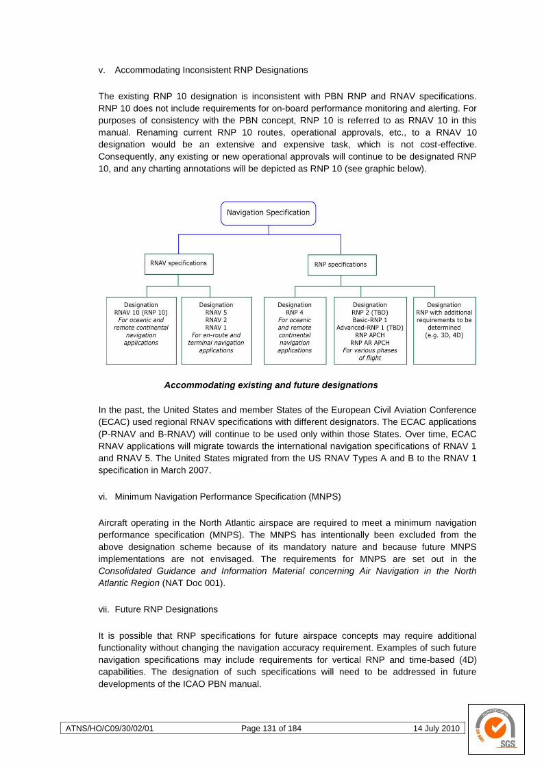
ATNS/HO/C09/30/02/01 Page 131 of 184 14 July 2010
v. Accommodating Inconsistent RNP Designations
The existing RNP 10 designation is inconsistent with PBN RNP and RNAV specifications.
RNP 10 does not include requirements for on-board performance monitoring and alerting. For
purposes of consistency with the PBN concept, RNP 10 is referred to as RNAV 10 in this
manual. Renaming current RNP 10 routes, operational approvals, etc., to a RNAV 10
designation would be an extensive and expensive task, which is not cost-effective.
Consequently, any existing or new operational approvals will continue to be designated RNP
10, and any charting annotations will be depicted as RNP 10 (see graphic below).
Accommodating existing and future designations
In the past, the United States and member States of the European Civil Aviation Conference
(ECAC) used regional RNAV specifications with different designators. The ECAC applications
(P-RNAV and B-RNAV) will continue to be used only within those States. Over time, ECAC
RNAV applications will migrate towards the international navigation specifications of RNAV 1
and RNAV 5. The United States migrated from the US RNAV Types A and B to the RNAV 1
specification in March 2007.
vi. Minimum Navigation Performance Specification (MNPS)
Aircraft operating in the North Atlantic airspace are required to meet a minimum navigation
performance specification (MNPS). The MNPS has intentionally been excluded from the
above designation scheme because of its mandatory nature and because future MNPS
implementations are not envisaged. The requirements for MNPS are set out in the
Consolidated Guidance and Information Material concerning Air Navigation in the North
Atlantic Region (NAT Doc 001).
vii. Future RNP Designations
It is possible that RNP specifications for future airspace concepts may require additional
functionality without changing the navigation accuracy requirement. Examples of such future
navigation specifications may include requirements for vertical RNP and time-based (4D)
capabilities. The designation of such specifications will need to be addressed in future
developments of the ICAO PBN manual.
ATNS/HO/C09/30/02/01 Page 132 of 184 14 July 2010
4.1.3 NAVAID Infrastructure
NAVAID Infrastructure comprises the NAVAIDs that support or provide the position
capabilities and is referred to as ground- or space-based NAVAIDS. NAVAIDS are
categorised as follows:
Ground-based NAVAIDs include DME and VOR, or
Space-based NAVAIDs include GNSS elements.
4.1.4 Navigation Application
This is the application of a navigation specification and associated NAVAID infrastructure to
ATS routes, instrument approach procedures and/or defined airspace volume in accordance
with the airspace concept, i.e. the concept of matching the navigation specification against the
navigation aid infrastructure. Navigation application includes RNAV or RNP SIDs and STARs,
RNAV or RNP ATS routes and RNP approach procedures. The designator of a Navigation
Application matches the corresponding Navigation Specification, i.e.
A RNP application is supported by RNP specifications, and
A RNAV application is supported by RNAV specifications.
Navigation Applications indicating the designation of the required Navigation Specification
plus any established limitation imposed for the particular Navigation Application will be
outlined on the relevant instrument procedure charts and AIPs.
Application of navigation specification by flight phase:
Navigation
Specification
Flight Phase
En-route
Oceanic/remote
En-route
Continental
Arrival
Approach
Departure Initial Intermediate Final Missed
RNAV 10 10
RNAV 5 5 5
RNAV 2 2 2 2
RNAV 1 1 1 1b 1
RNP4 4
Basic-RNP1 1a,c 1a 1a 1a,b 1a,c
RNPAPCH 1 1 0.3 1
a. The navigation application is limited to use on STARs and SIDs only.
b. The area of application can only be used after the initial climb of a missed approach phase.
c. Beyond 30 NM from the airport reference point (ARP), the accuracy value for alerting becomes 2 NM.
ATNS/HO/C09/30/02/01 Page 133 of 184 14 July 2010
4.1.5 Future Developments
Under PBN, Navigation Applications will progress from 2D to 3D/4D. Consequently, on-board
performance monitoring and alerting is still to be developed in the vertical plane (vertical
RNP) and ongoing work is aimed at harmonising longitudinal and linear performance
requirements. It is also possible that angular performance requirements associated with
approach and landing may be included in the scope of PBN in the future. Similarly,
specifications to support helicopter-specific navigation applications and holding functional
requirements may also be included.
Operators are preparing for the application of trajectory-based operations (TBO), i.e. 3D and
4D RNAV operations. TBO presents lateral and vertical flight profile for aircraft that are
specific, but highly flexible and adaptable to operational needs. These types of operations
allow for ―real time‖ flight profile changes depending on the navigation accuracy required. This
type of operation also allows for the definition of climb and descent points as well as time of
arrival definition to meet the prevailing ATS requirement. The availability of this level of
navigation capability from takeoff to landing will ensure navigation accuracy along a route,
procedure or airspace both laterally and vertically.
As more reliance is placed on GNSS, the development of airspace concepts will increasingly
need to ensure the coherent integration of navigation, communication and ATS surveillance
enablers. Future ATM developments will allow different States to employ the most cost
effective and relevant navigation specifications. See the following example;
An example of different States employing different NAVAID solutions
to achieve a similar result.
The RNAV 1 specification in Volume II of this manual shows that any of the following
navigation sensors can meet its performance requirements: GNSS or DME/DME/IRU or
DME/DME. Sensors needed to satisfy the performance requirements for a RNAV 1
specification in a particular State are not only dependent on the aircraft on-board capability.
A limited DME infrastructure or GNSS policy considerations may lead the authorities to
impose specific navigation sensor requirements for a RNAV 1 specification in that State. As
such, State A‘s AIP could stipulate GNSS as a requirement for its RNAV 1 specification
because State A only has GNSS available in its navaid infrastructure. State B‘s AIP could
require DME/DME/IRU for its RNAV 1 specification (policy decision to not allow GNSS).
Each of these navigation specifications would be implemented as a RNAV 1 application.
However, aircraft equipped only with GNSS and approved for the RNAV 1 specification in
State A would not be approved to operate in State B.
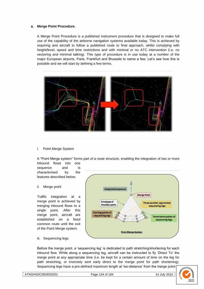
ATNS/HO/C09/30/02/01 Page 134 of 184 14 July 2010
a. Merge Point Procedure.
A Merge Point Procedure is a published instrument procedure that is designed to make full
use of the capability of the airborne navigation systems available today. This is achieved by
requiring and aircraft to follow a published route to final approach, whilst complying with
height/level, speed and time restrictions and with minimal or no ATC intervention (i.e. no
vectoring and minimal talking). This type of procedure is in use today at a number of the
major European airports, Paris, Frankfurt and Brussels to name a few. Let‘s see how this is
possible and we will start by defining a few terms.
i. Point Merge System
A ―Point Merge system‖ forms part of a route structure, enabling the integration of two or more
inbound flows into one
sequence and is
characterised by the
features described below.
ii. Merge point
Traffic integration at a
merge point is achieved by
merging inbound flows to a
single point. After this
merge point, aircraft are
established on a fixed
common route until the exit
of the Point Merge system.
iii. Sequencing legs
Before the merge point, a ‗sequencing leg‘ is dedicated to path stretching/shortening for each
inbound flow. While along a sequencing leg, aircraft can be instructed to fly ‗Direct To‘ the
merge point at any appropriate time (i.e. be kept for a certain amount of time on the leg for
path stretching, or inversely sent early direct to the merge point for path shortening).
Sequencing legs have a pre-defined maximum length at ‗iso-distance‘ from the merge point
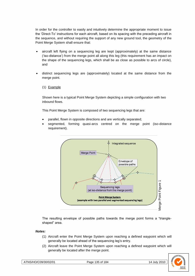
ATNS/HO/C09/30/02/01 Page 135 of 184 14 July 2010
Merg
e P
oin
t F
igure
1
In order for the controller to easily and intuitively determine the appropriate moment to issue
the ‗Direct-To‘ instructions for each aircraft, based on its spacing with the preceding aircraft in
the sequence, and without requiring the support of any new ground tool, the geometry of the
Point Merge System shall ensure that:
aircraft left flying on a sequencing leg are kept (approximately) at the same distance
(‗iso-distance‘) from the merge point all along this leg (this requirement has an impact on
the shape of the sequencing legs, which shall be as close as possible to arcs of circle),
and
distinct sequencing legs are (approximately) located at the same distance from the
merge point.
(1) Example
Shown here is a typical Point Merge System depicting a simple configuration with two
inbound flows.
This Point Merge System is composed of two sequencing legs that are:
parallel, flown in opposite directions and are vertically separated;
segmented, forming quasi-arcs centred on the merge point (iso-distance
requirement).
The resulting envelope of possible paths towards the merge point forms a ―triangle-
shaped‖ area.
Notes:
(1) Aircraft enter the Point Merge System upon reaching a defined waypoint which will
generally be located ahead of the sequencing leg‘s entry.
(2) Aircraft leave the Point Merge System upon reaching a defined waypoint which will
generally be located after the merge point.
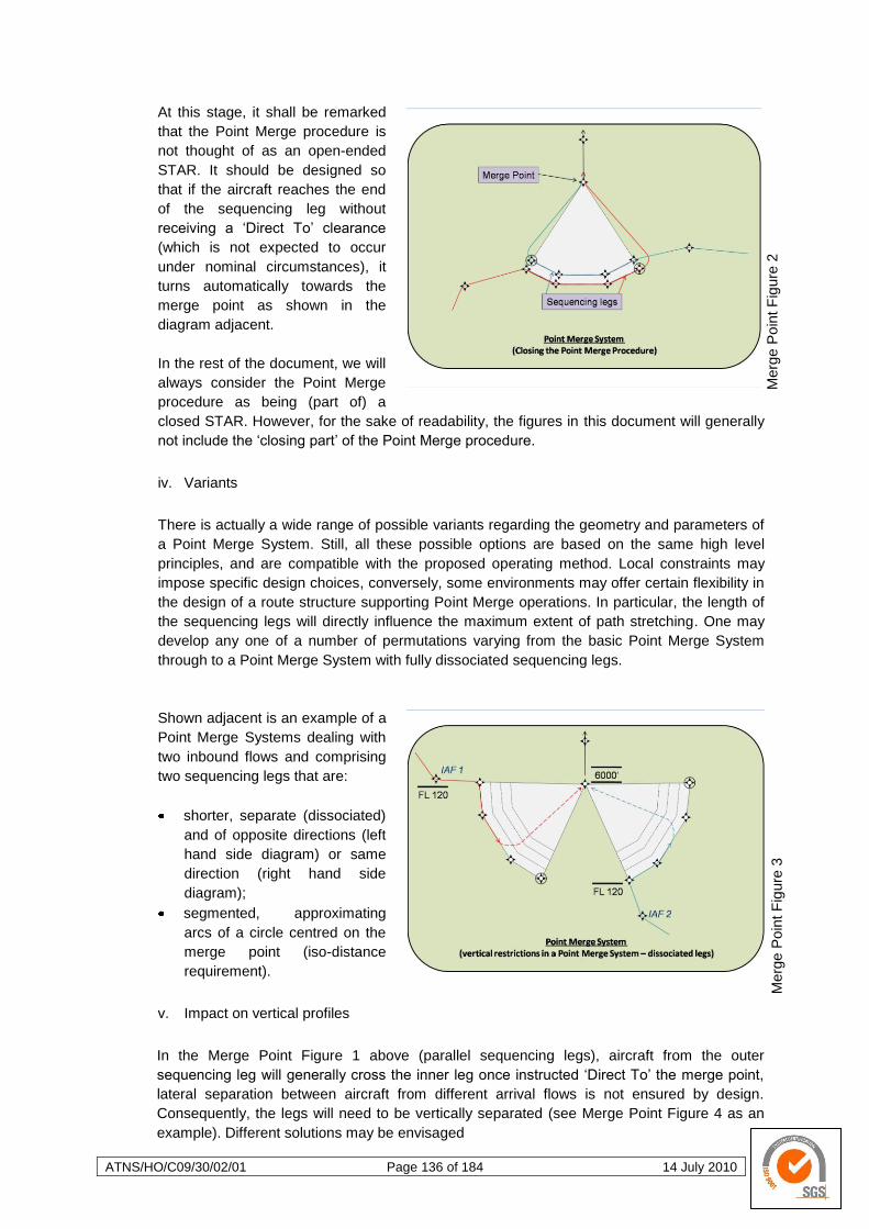
ATNS/HO/C09/30/02/01 Page 136 of 184 14 July 2010
Merg
e P
oin
t F
igure
3
Merg
e P
oin
t F
igure
2
At this stage, it shall be remarked
that the Point Merge procedure is
not thought of as an open-ended
STAR. It should be designed so
that if the aircraft reaches the end
of the sequencing leg without
receiving a ‗Direct To‘ clearance
(which is not expected to occur
under nominal circumstances), it
turns automatically towards the
merge point as shown in the
diagram adjacent.
In the rest of the document, we will
always consider the Point Merge
procedure as being (part of) a
closed STAR. However, for the sake of readability, the figures in this document will generally
not include the ‗closing part‘ of the Point Merge procedure.
iv. Variants
There is actually a wide range of possible variants regarding the geometry and parameters of
a Point Merge System. Still, all these possible options are based on the same high level
principles, and are compatible with the proposed operating method. Local constraints may
impose specific design choices, conversely, some environments may offer certain flexibility in
the design of a route structure supporting Point Merge operations. In particular, the length of
the sequencing legs will directly influence the maximum extent of path stretching. One may
develop any one of a number of permutations varying from the basic Point Merge System
through to a Point Merge System with fully dissociated sequencing legs.
Shown adjacent is an example of a
Point Merge Systems dealing with
two inbound flows and comprising
two sequencing legs that are:
shorter, separate (dissociated)
and of opposite directions (left
hand side diagram) or same
direction (right hand side
diagram);
segmented, approximating
arcs of a circle centred on the
merge point (iso-distance
requirement).
v. Impact on vertical profiles
In the Merge Point Figure 1 above (parallel sequencing legs), aircraft from the outer
sequencing leg will generally cross the inner leg once instructed ‗Direct To‘ the merge point,
lateral separation between aircraft from different arrival flows is not ensured by design.
Consequently, the legs will need to be vertically separated (see Merge Point Figure 4 as an
example). Different solutions may be envisaged
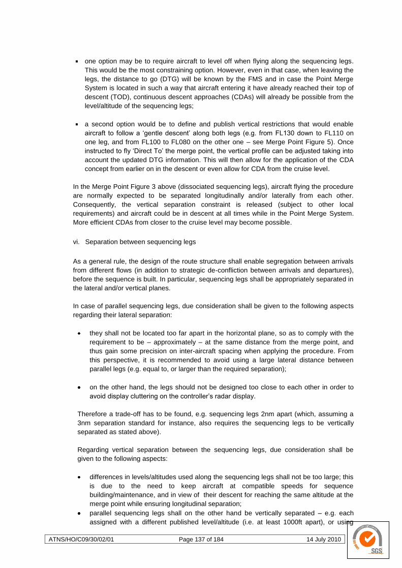
ATNS/HO/C09/30/02/01 Page 137 of 184 14 July 2010
one option may be to require aircraft to level off when flying along the sequencing legs.
This would be the most constraining option. However, even in that case, when leaving the
legs, the distance to go (DTG) will be known by the FMS and in case the Point Merge
System is located in such a way that aircraft entering it have already reached their top of
descent (TOD), continuous descent approaches (CDAs) will already be possible from the
level/altitude of the sequencing legs;
a second option would be to define and publish vertical restrictions that would enable
aircraft to follow a ‗gentle descent‘ along both legs (e.g. from FL130 down to FL110 on
one leg, and from FL100 to FL080 on the other one – see Merge Point Figure 5). Once
instructed to fly ‗Direct To‘ the merge point, the vertical profile can be adjusted taking into
account the updated DTG information. This will then allow for the application of the CDA
concept from earlier on in the descent or even allow for CDA from the cruise level.
In the Merge Point Figure 3 above (dissociated sequencing legs), aircraft flying the procedure
are normally expected to be separated longitudinally and/or laterally from each other.
Consequently, the vertical separation constraint is released (subject to other local
requirements) and aircraft could be in descent at all times while in the Point Merge System.
More efficient CDAs from closer to the cruise level may become possible.
vi. Separation between sequencing legs
As a general rule, the design of the route structure shall enable segregation between arrivals
from different flows (in addition to strategic de-confliction between arrivals and departures),
before the sequence is built. In particular, sequencing legs shall be appropriately separated in
the lateral and/or vertical planes.
In case of parallel sequencing legs, due consideration shall be given to the following aspects
regarding their lateral separation:
they shall not be located too far apart in the horizontal plane, so as to comply with the
requirement to be – approximately – at the same distance from the merge point, and
thus gain some precision on inter-aircraft spacing when applying the procedure. From
this perspective, it is recommended to avoid using a large lateral distance between
parallel legs (e.g. equal to, or larger than the required separation);
on the other hand, the legs should not be designed too close to each other in order to
avoid display cluttering on the controller‘s radar display.
Therefore a trade-off has to be found, e.g. sequencing legs 2nm apart (which, assuming a
3nm separation standard for instance, also requires the sequencing legs to be vertically
separated as stated above).
Regarding vertical separation between the sequencing legs, due consideration shall be
given to the following aspects:
differences in levels/altitudes used along the sequencing legs shall not be too large; this
is due to the need to keep aircraft at compatible speeds for sequence
building/maintenance, and in view of their descent for reaching the same altitude at the
merge point while ensuring longitudinal separation;
parallel sequencing legs shall on the other hand be vertically separated – e.g. each
assigned with a different published level/altitude (i.e. at least 1000ft apart), or using
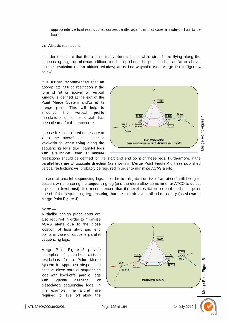
ATNS/HO/C09/30/02/01 Page 138 of 184 14 July 2010
Merg
e P
oin
t F
igure
5
Merg
e P
oin
t F
igure
4
appropriate vertical restrictions; consequently, again, in that case a trade-off has to be
found.
vii. Altitude restrictions
In order to ensure that there is no inadvertent descent while aircraft are flying along the
sequencing leg, the minimum altitude for the leg should be published as an ‗at or above‘
altitude restriction (or an altitude window) at its last waypoint (see Merge Point Figure 4
below).
It is further recommended that an
appropriate altitude restriction in the
form of ‗at or above‘ or vertical
window is defined at the exit of the
Point Merge System and/or at its
merge point. This will help to
influence the vertical profile
calculations once the aircraft has
been cleared for the procedure.
In case it is considered necessary to
keep the aircraft at a specific
level/altitude when flying along the
sequencing legs (e.g. parallel legs
with levelling-off), then ‗at‘ altitude
restrictions should be defined for the start and end point of these legs. Furthermore, if the
parallel legs are of opposite direction (as shown in Merge Point Figure 4), these published
vertical restrictions will probably be required in order to minimise ACAS alerts.
In case of parallel sequencing legs, in order to mitigate the risk of an aircraft still being in
descent whilst entering the sequencing leg (and therefore allow some time for ATCO to detect
a potential level bust), it is recommended that the level restriction be published on a point
ahead of the sequencing leg, ensuring that the aircraft levels off prior to entry (as shown in
Merge Point Figure 4).
Note: —
A similar design precautions are
also required in order to minimise
ACAS alerts due to the close
location of legs start and end
points in case of opposite parallel
sequencing legs.
Merge Point Figure 5 provide
examples of published altitude
restrictions for a Point Merge
System in Approach airspace, in
case of close parallel sequencing
legs with level-offs, parallel legs
with ‗gentle descent‘, or
dissociated sequencing legs. In
this example, the aircraft are
required to level off along the
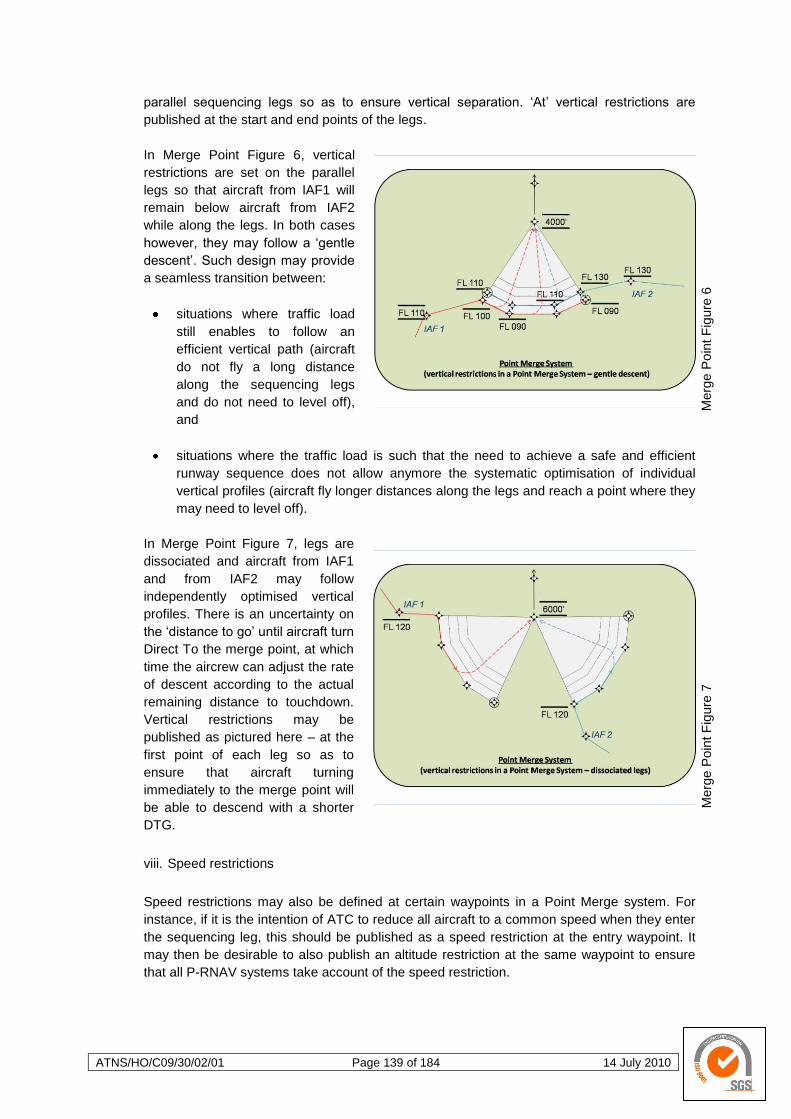
ATNS/HO/C09/30/02/01 Page 139 of 184 14 July 2010
Merg
e P
oin
t F
igure
7
Merg
e P
oin
t F
igure
6
parallel sequencing legs so as to ensure vertical separation. ‗At‘ vertical restrictions are
published at the start and end points of the legs.
In Merge Point Figure 6, vertical
restrictions are set on the parallel
legs so that aircraft from IAF1 will
remain below aircraft from IAF2
while along the legs. In both cases
however, they may follow a ‗gentle
descent‘. Such design may provide
a seamless transition between:
situations where traffic load
still enables to follow an
efficient vertical path (aircraft
do not fly a long distance
along the sequencing legs
and do not need to level off),
and
situations where the traffic load is such that the need to achieve a safe and efficient
runway sequence does not allow anymore the systematic optimisation of individual
vertical profiles (aircraft fly longer distances along the legs and reach a point where they
may need to level off).
In Merge Point Figure 7, legs are
dissociated and aircraft from IAF1
and from IAF2 may follow
independently optimised vertical
profiles. There is an uncertainty on
the ‗distance to go‘ until aircraft turn
Direct To the merge point, at which
time the aircrew can adjust the rate
of descent according to the actual
remaining distance to touchdown.
Vertical restrictions may be
published as pictured here – at the
first point of each leg so as to
ensure that aircraft turning
immediately to the merge point will
be able to descend with a shorter
DTG.
viii. Speed restrictions
Speed restrictions may also be defined at certain waypoints in a Point Merge system. For
instance, if it is the intention of ATC to reduce all aircraft to a common speed when they enter
the sequencing leg, this should be published as a speed restriction at the entry waypoint. It
may then be desirable to also publish an altitude restriction at the same waypoint to ensure
that all P-RNAV systems take account of the speed restriction.
ATNS/HO/C09/30/02/01 Page 140 of 184 14 July 2010
ix. Other charting aspects
Waypoints in a Point Merge System (including the merging point) should be fly-by waypoints,
with the exception of the last point at the end of the sequencing leg in the ‗closing part‘ of the
procedure which should be a fly-over waypoint.
The waypoint names in a Point Merge System shall conform to naming conventions such as
those published for RNAV waypoints. Waypoints on the sequencing legs could be identified
using the alphanumeric naming conventions. The merge point should be considered as a
strategic waypoint to ATC, and thus be named using 5 letter globally unique pronounceable
ICAO Name codes.
The Point Merge procedure should be detailed in the AIP, or in a supporting AIC. The charts
should not be cluttered with detailed notes about the concept apart from a note stating ‗Point
Merge procedures in operation, expect clearance direct to merge points (WPT NAMES) once
past IAF. CDA profiles to be followed once inbound to the merge point‘, or a similar
statement.

ATNS/HO/C09/30/02/01 Page 141 of 184 14 July 2010
4.2 Airspace Concept
4.2.1 Introduction
An airspace concept may be viewed as
a general vision or a master plan for a
particular airspace. Based on particular
principles, an airspace concept is
geared towards specific objectives.
Airspace concepts need to include a
certain level of detail if changes are to
be introduced within a particular portion
of airspace. Details could explain, for
example, airspace organization and
management and the roles to be
played by various stakeholders and
airspace users. Airspace concepts may
also describe the different roles and
responsibilities, mechanisms used and the relationships between people and machines.
Strategic objectives drive the general vision of the airspace concept. These objectives are usually
identified by airspace users, air traffic management (ATM), airports as well as environmental and
government policy. It is the function of the airspace concept and the concept of operations to respond
to these requirements. The strategic objectives which most commonly drive airspace concepts are
safety, capacity, efficiency, access and the environment. As Examples 1 and 2 below suggest,
strategic objectives can result in changes being introduced to the airspace concept.
Example 1
Safety: The design of RNP instrument approach procedures could be a way of
increasing safety (by reducing Controlled Flights into Terrain (CFIT).
Capacity: Planning the addition of an extra runway at an airport to increase capacity will
trigger a change to the airspace concept (new approaches to SIDs and STAR
required).
Efficiency: A user requirement to optimise flight profiles on departure and arrival could
make flights more efficient in terms of fuel burn.
Environment: Requirements for reduced emissions, noise preferential routes or continuous
descent arrivals/approaches (CDA), are environmental motivators for change.
Access: A requirement to provide an approach with lower minima than supported by
conventional procedures, to ensure continued access to the airport during
bad weather, may result in the development and publication of a RNP
approach to that runway.

ATNS/HO/C09/30/02/01 Page 142 of 184 14 July 2010
Example 2
Although GNSS is associated primarily with navigation, GNSS is also the backbone of ADS-B
surveillance applications. As such, GNSS positioning and track-keeping functions are no
longer ―confined‖ to being a navigation enabler to an airspace concept. GNSS, in this case, is
also an ATS surveillance enabler. The same is true of data-link communications: data are
used by an ATS surveillance system (for example, in ADS-B and navigation).
4.2.2 The Airspace Concept
a. Airspace Concepts and Navigation Applications.
The cascade effect from strategic objectives to the airspace concept places requirements on the
various ―enablers‖ such as communication, navigation, ATS surveillance, air traffic management
and flight operations. The navigation functional requirements within a Performance-Based
Navigation context need to be identified. These navigation functionalities are formalised in a
navigation specification which, together with a navigation aid infrastructure, supports a particular
navigation application. As part of an airspace concept, navigation applications also have a
relationship to communication, ATS surveillance, ATM, ATC tools and flight operations, which are
also inherent in the airspace concept.
Relationship: Performance-Based Navigation and Airspace Concept
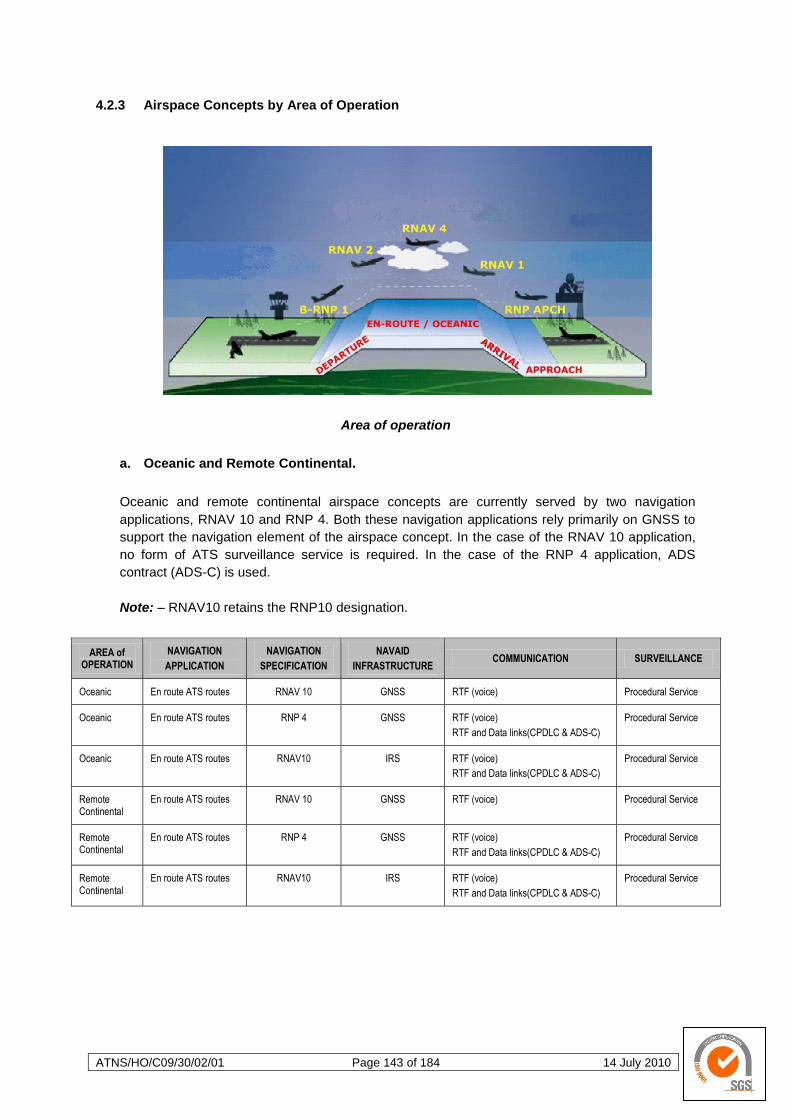
ATNS/HO/C09/30/02/01 Page 143 of 184 14 July 2010
4.2.3 Airspace Concepts by Area of Operation
Area of operation
a. Oceanic and Remote Continental.
Oceanic and remote continental airspace concepts are currently served by two navigation
applications, RNAV 10 and RNP 4. Both these navigation applications rely primarily on GNSS to
support the navigation element of the airspace concept. In the case of the RNAV 10 application,
no form of ATS surveillance service is required. In the case of the RNP 4 application, ADS
contract (ADS-C) is used.
Note: – RNAV10 retains the RNP10 designation.
AREA of OPERATION
NAVIGATION
APPLICATION
NAVIGATION
SPECIFICATION
NAVAID
INFRASTRUCTURE COMMUNICATION SURVEILLANCE
Oceanic En route ATS routes RNAV 10 GNSS RTF (voice) Procedural Service
Oceanic En route ATS routes RNP 4 GNSS RTF (voice)
RTF and Data links(CPDLC & ADS-C)
Procedural Service
Oceanic En route ATS routes RNAV10 IRS RTF (voice)
RTF and Data links(CPDLC & ADS-C)
Procedural Service
Remote Continental
En route ATS routes RNAV 10 GNSS RTF (voice) Procedural Service
Remote Continental
En route ATS routes RNP 4 GNSS RTF (voice)
RTF and Data links(CPDLC & ADS-C)
Procedural Service
Remote Continental
En route ATS routes RNAV10 IRS RTF (voice)
RTF and Data links(CPDLC & ADS-C)
Procedural Service
ATNS/HO/C09/30/02/01 Page 144 of 184 14 July 2010
b. Continental En-Route.
Continental en-route airspace concepts are currently supported by RNAV applications. RNAV 5 is
used in the Middle East (MID) and European (EUR) Regions. It is designated as B-RNAV (Basic
RNAV in Europe and RNP 5 in the Middle East. In the United States, a RNAV 2 application
supports an en-route continental airspace concept. At present, continental RNAV applications
support airspace concepts which include radar surveillance and direct controller pilot
communication (voice).
AREA of OPERATION
NAVIGATION
APPLICATION
NAVIGATION
SPECIFICATION
NAVAID
INFRASTRUCTURE COMMUNICATION SURVEILLANCE
Continental
En-route
En route ATS routes
RNAV 5 GNSS
DME/DME
VOR/DME
RTF (voice) ATS Surveillance Service
Continental
En-route
En route ATS routes
RNP 1 GNSS
DME/DME
RTF (voice)
Procedural Service
Continental
En-route
En route ATS routes
RNAV 2 no IRS
RNAV 1 with IRS
RNAV 1 no IRS but adequate DME
GNSS
DME/DME
RTF (voice)
Procedural Service
Continental
En-route
En route ATS routes
None available GNSS
DME/DME
RTF (voice)
Procedural Service
c. Terminal Airspace: Arrival and Departure.
Existing terminal airspace concepts, which include arrival and departure, are supported by RNAV
applications. These are currently used in the European (EUR) Region and the United States. The
European terminal airspace RNAV application is known as Precision RNAV (P-RNAV). As
indicate in the PBN Manual Doc. 9813 Volume II, although the RNAV 1 specification shares a
common navigation accuracy with P-RNAV, this regional navigation specification does not satisfy
the full requirements of the RNAV 1 specification shown in Volume II. As of the publication of this
manual, the United States terminal airspace application formerly known as US RNAV Type B has
been aligned with the PBN concept and is now called RNAV 1. Basic-RNP 1 has been developed
primarily for application in non-radar, low-density terminal airspace. In future, more RNP
applications are expected to be developed for both en-route and terminal airspace.
AREA of OPERATION
NAVIGATION
APPLICATION
NAVIGATION
SPECIFICATION
NAVAID
INFRASTRUCTURE COMMUNICATION SURVEILLANCE
Terminal SIDs and STARS
RNAV 2 no IRS
RNAV 1 with IRS
RNAV 1 no IRS but adequate DME
GNSS
DME/DME
RTF (voice)
ATS Surveillance Service
Terminal SIDs and STARS
Basic - RNP 1 GNSS
RTF (voice)
Procedural Service
Terminal SIDs and STARS
Basic - RNP 1
RNAV 1 with GNSS only
GNSS
DME/DME
RTF (voice)
ATS Surveillance Service
ATNS/HO/C09/30/02/01 Page 145 of 184 14 July 2010
d. Approach.
Approach concepts cover all segments of the instrument approach, i.e. initial, intermediate, final
and missed approach. They will increasingly call for RNP specifications requiring a navigation
accuracy of 0.3 NM to 0.1 NM or lower. Typically, three sorts of RNP applications are
characteristic of this phase of flight: new procedures to runways never served by an instrument
procedure, procedures either replacing or serving as backup to existing instrument procedures
based on different technologies, and procedures developed to enhance airport access in
demanding environments. The relevant RNP specifications covered in the PBN Manual Doc. 9813
Volume II are RNP APCH and RNP AR APCH.
AREA of OPERATION
NAVIGATION
APPLICATION
NAVIGATION
SPECIFICATION
NAVAID
INFRASTRUCTURE COMMUNICATION SURVEILLANCE
Approach Approach RNP APCH GNSS
RTF (voice)
ATS Surveillance Service
Approach Approach RNP APCH GNSS
RTF (voice)
Procedural* Service
Approach Approach RNP AR APCH GNSS
RTF (voice)
Procedural ** Service
Approach Approach RNP AR APCH GNSS
RTF (voice)
ATS ** Surveillance Service
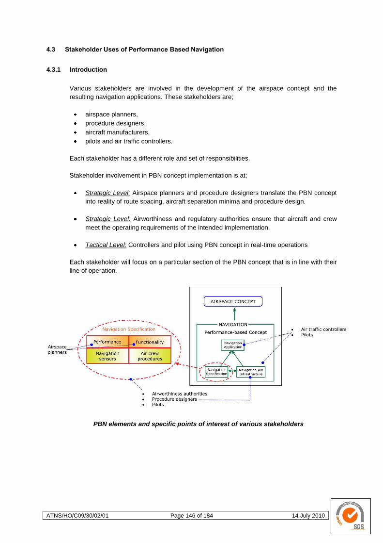
ATNS/HO/C09/30/02/01 Page 146 of 184 14 July 2010
4.3 Stakeholder Uses of Performance Based Navigation
4.3.1 Introduction
Various stakeholders are involved in the development of the airspace concept and the
resulting navigation applications. These stakeholders are;
airspace planners,
procedure designers,
aircraft manufacturers,
pilots and air traffic controllers.
Each stakeholder has a different role and set of responsibilities.
Stakeholder involvement in PBN concept implementation is at;
Strategic Level: Airspace planners and procedure designers translate the PBN concept
into reality of route spacing, aircraft separation minima and procedure design.
Strategic Level: Airworthiness and regulatory authorities ensure that aircraft and crew
meet the operating requirements of the intended implementation.
Tactical Level: Controllers and pilot using PBN concept in real-time operations
Each stakeholder will focus on a particular section of the PBN concept that is in line with their
line of operation.
PBN elements and specific points of interest of various stakeholders
ATNS/HO/C09/30/02/01 Page 147 of 184 14 July 2010
4.3.2 Airspace Planning
The two major elements of airspace planning are determination of separation minima to be
applied and route spacing for use by aircraft. The Manual on Airspace Planning Methodology
for the Determination of separation Minima (Doc 9689) is a key reference document planners
should consult.
Separation minima and route spacing can generally be described as being a function of three
factors:
Navigation performance based on the PBN concept.
Aircraft‘s exposure to risk i.e. the route configuration, traffic density and operational
error.
The mitigation measures which are available to reduce risk i.e. communication,
surveillance which also include ATC procedures and other necessary tools.
Generic model used to determine separation and ATS route spacing
Aircraft-to-aircraft separation and ATS route spacing are not exactly the same. As such, the
degree of complexity of the ―equation‖ depicted graphically in the figures above depends on
whether separation between two aircraft or route spacing criteria is being determined.
Aircraft-to-aircraft separation, for example, is usually applied between two aircraft and as a
consequence, the traffic density part of the risk is usually considered to be a single aircraft
pair.
For route spacing purposes, this is not the case: the traffic density is determined by the
volume of air traffic operating along the spaced ATS routes. This means that if aircraft in
a particular portion of airspace are all capable of the same navigation performance, one
could expect the separation minima between a single aircraft pair to be less than the
spacing required for parallel ATS routes.
The complexity of determining route spacing and separation minima is affected by the
availability of an ATS surveillance service and the type of communication used. If an
ATS surveillance service is available, this means that the risk can be mitigated by
including requirements for ATC intervention.
ATNS/HO/C09/30/02/01 Page 148 of 184 14 July 2010
a. Impact of PBN on airspace planning.
When separation minima and route spacing are determined using a conventional sensor-
based approach, the navigation performance data used to determine the separation minima
or route spacing depend on the accuracy of the raw data from specific navigation aids such
as VOR, DME or NDB. In contrast, PBN requires a RNAV system that integrates raw
navigation data to provide a positioning and navigation solution. In determining separation
minima and route spacing in a PBN context, this integrated navigation performance ―output‖ is
used.
It needs to be remembered that the navigation performance required from the RNAV system
is part of the navigation specification. To determine separation minima and route spacing,
airspace planners fully exploit that part of the navigation specification which prescribes the
performance required from the RNAV system. Airspace planners also make use of the
required performance, namely, accuracy, integrity, availability and continuity to determine
route spacing and separation minima.
RNAV specifications and RNP specifications are applied in this process. It is expected, for
example, that the separation minima and route spacing derived from a RNP 1 specification
will be smaller than those derived from a RNAV 1 specification, though the extent of this
improvement has yet to be assessed.
In procedurally controlled airspace, separation minima and route spacing based on RNP
specifications are expected to provide a greater benefit than those based on RNAV
specifications. This is because the on-board performance monitoring and alerting function
could alleviate the absence of ATS surveillance service by providing an alternative means of
risk mitigation.
4.3.3 Instrument Flight Procedure Design
Instrument flight procedure design includes the construction of routes, which include arrivals,
departures and approach procedures. These procedures consist of a series of predetermined
manoeuvres to be conducted solely by reference to flight instruments with specified protection
from obstacles.
States are responsible for ensuring that all published instrument flight procedures in their
airspace can be flown safely by the relevant aircraft. Safety is not only accomplished by
application of the technical criteria in the PANS-OPS (Doc 8168) and associated provisions,
but also requires measures that control the quality of the process used to apply that criteria,
which may include;
regulation,
air traffic monitoring,
ground validation and flight validation.
These measures must ensure the quality and safety of the procedure design product through
review, verification, coordination, and validation at appropriate points in the process, so that
corrections can be made at the earliest opportunity in the process.
The following paragraphs regarding instrument flight procedure design describe conventional
procedure design and sensor-dependent RNAV procedure design, their disadvantages and
the issues that led up to PBN.
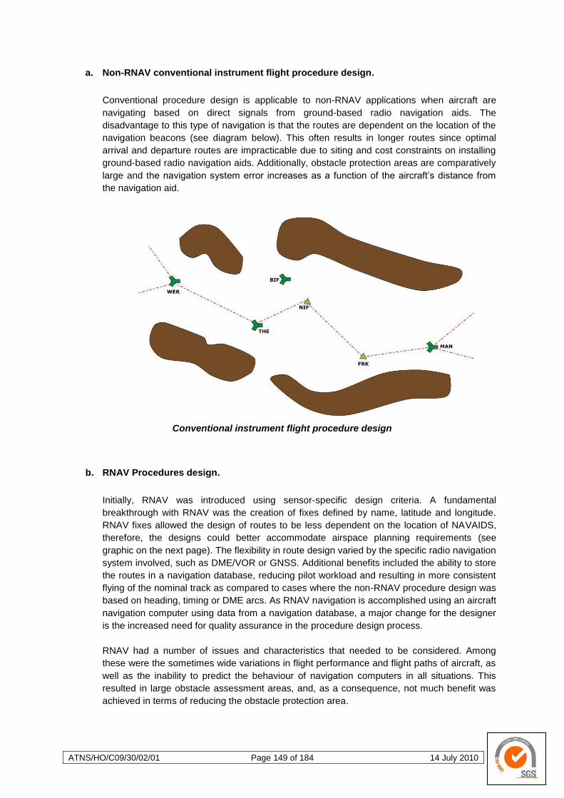
ATNS/HO/C09/30/02/01 Page 149 of 184 14 July 2010
a. Non-RNAV conventional instrument flight procedure design.
Conventional procedure design is applicable to non-RNAV applications when aircraft are
navigating based on direct signals from ground-based radio navigation aids. The
disadvantage to this type of navigation is that the routes are dependent on the location of the
navigation beacons (see diagram below). This often results in longer routes since optimal
arrival and departure routes are impracticable due to siting and cost constraints on installing
ground-based radio navigation aids. Additionally, obstacle protection areas are comparatively
large and the navigation system error increases as a function of the aircraft‘s distance from
the navigation aid.
Conventional instrument flight procedure design
b. RNAV Procedures design.
Initially, RNAV was introduced using sensor-specific design criteria. A fundamental
breakthrough with RNAV was the creation of fixes defined by name, latitude and longitude.
RNAV fixes allowed the design of routes to be less dependent on the location of NAVAIDS,
therefore, the designs could better accommodate airspace planning requirements (see
graphic on the next page). The flexibility in route design varied by the specific radio navigation
system involved, such as DME/VOR or GNSS. Additional benefits included the ability to store
the routes in a navigation database, reducing pilot workload and resulting in more consistent
flying of the nominal track as compared to cases where the non-RNAV procedure design was
based on heading, timing or DME arcs. As RNAV navigation is accomplished using an aircraft
navigation computer using data from a navigation database, a major change for the designer
is the increased need for quality assurance in the procedure design process.
RNAV had a number of issues and characteristics that needed to be considered. Among
these were the sometimes wide variations in flight performance and flight paths of aircraft, as
well as the inability to predict the behaviour of navigation computers in all situations. This
resulted in large obstacle assessment areas, and, as a consequence, not much benefit was
achieved in terms of reducing the obstacle protection area.
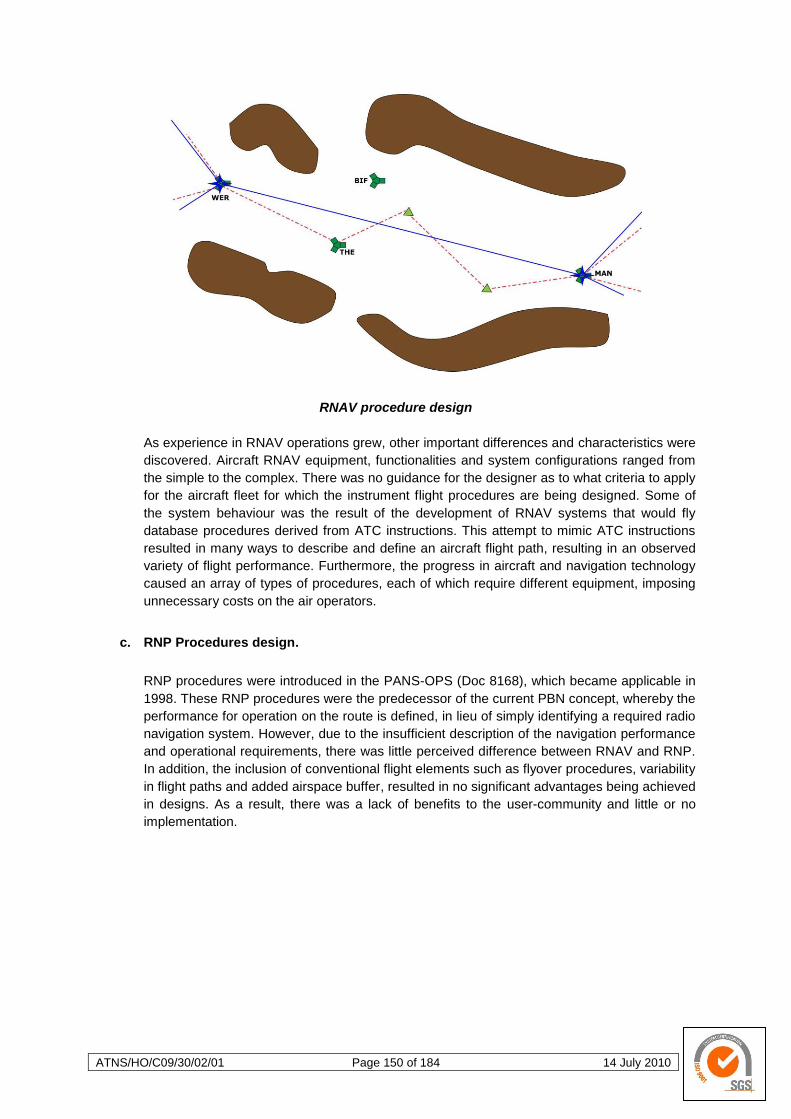
ATNS/HO/C09/30/02/01 Page 150 of 184 14 July 2010
RNAV procedure design
As experience in RNAV operations grew, other important differences and characteristics were
discovered. Aircraft RNAV equipment, functionalities and system configurations ranged from
the simple to the complex. There was no guidance for the designer as to what criteria to apply
for the aircraft fleet for which the instrument flight procedures are being designed. Some of
the system behaviour was the result of the development of RNAV systems that would fly
database procedures derived from ATC instructions. This attempt to mimic ATC instructions
resulted in many ways to describe and define an aircraft flight path, resulting in an observed
variety of flight performance. Furthermore, the progress in aircraft and navigation technology
caused an array of types of procedures, each of which require different equipment, imposing
unnecessary costs on the air operators.
c. RNP Procedures design.
RNP procedures were introduced in the PANS-OPS (Doc 8168), which became applicable in
1998. These RNP procedures were the predecessor of the current PBN concept, whereby the
performance for operation on the route is defined, in lieu of simply identifying a required radio
navigation system. However, due to the insufficient description of the navigation performance
and operational requirements, there was little perceived difference between RNAV and RNP.
In addition, the inclusion of conventional flight elements such as flyover procedures, variability
in flight paths and added airspace buffer, resulted in no significant advantages being achieved
in designs. As a result, there was a lack of benefits to the user-community and little or no
implementation.
ATNS/HO/C09/30/02/01 Page 151 of 184 14 July 2010
d. PBN Procedures design.
Area navigation using PBN is a performance-based operation in which the navigation
performance characteristics of the aircraft are well specified and the problems described
above for the original RNAV and RNP criteria can be resolved. The performance-based
descriptions address various aircraft characteristics that were causing variations in flight
trajectories, leading to more repeatable, reliable and predictable flight tracking, as well as
smaller obstacle assessment areas. Examples of RNP APPROACH (RNP APCH) and RNP
AUTHORISATION REQUIRED APPROACH (RNP AR APCH) are shown in the figures below.
Examples of RNP APCH (left) and RNP AR APCH (right) procedures design
Note: — The fundamental advantage of the RNP AR APCH over the RNP APCH is the fact
that AR procedures may be designed to allow operations closer to obstructions
(most often high ground) and thus increase access to obstacle rich aerodrome
environments.
The main change for the designers will be that they will not be designing for a specific sensor
but according to a navigation specification (e.g. RNAV 1). The selection of the appropriate
navigation specification is based on the airspace requirements, the available NAVAID
infrastructure, and the equipage and operational capability of aircraft expected to use the
route. For example, where an airspace requirement is for RNAV-1 or RNAV-2, the available
navigation infrastructure would have to be basic GNSS or DME/DME, and aircraft would be
required to utilise either to conduct operations. Volume II of the ICAO PBN Manual (ICAO Doc
9613) provides a more explicit and complete navigation specification for the aircraft and
operator as compared to PANS-OPS (Doc 8168), Volume I. The procedure design along with
qualified aircraft and operators result in greater reliability, repeatability and predictability of the
aircraft flight path. It should be understood that no matter what infrastructure is provided, the
designer may still apply the same general design rules in fix and path placement; however,
adjustments may be required based upon the associated obstacle clearance or separation
criteria.
Integration of the aircraft and operational criteria will enable procedure design criteria to be
updated. A first effort to create such criteria is for the RNP AR APCH navigation specification.
In this case, the design criteria take full account of the aircraft capabilities and are fully
integrated with the aircraft approval and qualification requirements. The tightly integrated
relationship between aircraft, operational and procedure design criteria for RNP AR APCH
requires closer examination of aircraft qualification and operator approval, since special
authorisation is required. This additional requirement will incur cost to the airlines and will
make these types of procedures only cost beneficial in cases where other procedure design
criteria and solutions will not fit.
ATNS/HO/C09/30/02/01 Page 152 of 184 14 July 2010
4.3.4 Airworthiness and Operational Approval
Aircraft should be equipped with a RNAV system able to support the desired navigation
application. The RNAV system and aircraft operations must be compliant with regulatory
material (still to developed and published for South Africa) that reflects the navigation
specification (not yet defined for South Africa) developed for a particular navigation
application as stated in PBN Manual Doc. 9813 Volume II and approved by the appropriate
regulatory authority for the operation.
The navigation specification details the flight crew and aircraft requirements needed to
support the navigation application. This specification includes the level of navigation
performance, functional capabilities, and operational considerations required for the RNAV
system. The RNAV system installation should be certified in accordance with the ICAO Annex
8 — Airworthiness of Aircraft and operational procedures should respect the applicable
aircraft flight manual limitations, if any.
The RNAV system should be operated in accordance with recommended practices described
in the ICAO Annex 6 — Operation of Aircraft and PANS-OPS (Doc 8168), Volume I. Flight
crew and/or operators should adhere to operational limitations required for the navigation
application.
All assumptions related to the navigation application are listed in the navigation specification.
Review of these assumptions is necessary when proceeding to the airworthiness and
operational approval process. Operators and flight crew are responsible for checking that the
installed RNAV system is operated in areas where the airspace concept and the NAVAID
infrastructure described in the navigation specification is fulfilled. To ease this process,
certification and/or operational documentation should clearly identify compliance with the
related navigation specification.
a. Airworthiness approval process.
The airworthiness approval process assures that each item of the RNAV equipment installed
is of a type and design appropriate to its intended function and that the installation functions
properly under foreseeable operating conditions. Additionally, the airworthiness approval
process identifies any installation limitations that need to be considered for operational
approval. Such limitations and other information relevant to the approval of the RNAV system
installation are documented in the Aircraft Flight Manual (AFM), or AFM Supplement, as
applicable. Information may also be repeated and expanded upon in other documents such
as Pilot Operating Handbooks (POH) or flight crew operating manuals. The airworthiness
approval process is well established among States of the Operators and this process refers to
the intended function of the navigation specification to be applied.
i. Approval of RNAV systems for RNAV-X operations
The RNAV system installed should be compliant with a set of basic performance
requirements as described in the navigation specification, which defines accuracy, integrity
and continuity criteria. It should also be compliant with a set of specific functional
requirements, have a navigation database, and support each specific path terminator as
required by the navigation specification.
Note: — For certain navigation applications, a navigation database may be optional.
ATNS/HO/C09/30/02/01 Page 153 of 184 14 July 2010
For a multi-sensor RNAV system, an assessment should be conducted to establish which
sensors are compliant with the performance requirement described in the navigation
specification. The navigation specification generally indicates if a single or a dual installation
is necessary to fulfil availability and/or continuity requirements. The airspace concept and
NAVAID infrastructure are key elements in deciding if a single or a dual installation is
necessary.
ii. Approval of RNP systems for RNP-X operations
The RNP system installed should be compliant with a set of basic RNP performance
requirements, as described in the navigation specification, which should include an on-board
performance monitoring and alerting function. It should also be compliant with a set of specific
functional requirements, have a navigation database, and should support each specific path
terminator as required by the navigation specification.
For a multi-sensor RNP system, an assessment should be conducted to establish sensors
which are compliant with the RNP performance requirement described in the RNP
specification.
b. Operational approval.
The aircraft must be equipped with a RNAV system enabling the flight crew to navigate in
accordance with operational criteria as defined in the navigation specification. The State of
the Operator is the authority responsible for approving flight operations. The authority must be
satisfied that operational programmes are adequate. Training programmes and operations
manuals should be evaluated.
i. General RNAV approval process
The operational approval process first assumes that the corresponding
installation/airworthiness approval has been granted. During operation, the crew should
adhere to any limitations set out in the AFM and AFM supplements. Normal procedures are
provided in the navigation specification, including detailed necessary crew action to be
conducted during pre-flight planning, prior to commencing the procedure and during the
procedure.
Abnormal procedures are provided in the navigation specification, including detailed crew
action to be conducted in case of on-board RNAV system failure and in case of system
inability to maintain the prescribed performance of the on-board monitoring and alerting
functions.
The operator should have in place a system for investigating events affecting the safety of
operations in order to determine their origin (coded procedure, accuracy problem, etc.).
The minimum equipment list (MEL) should identify the minimum equipment necessary to
satisfy the navigation application.
ii. Flight crew training
Each pilot must receive appropriate training, briefings and guidance material in order to safely
conduct an operation.
ATNS/HO/C09/30/02/01 Page 154 of 184 14 July 2010
iii. Navigation database management
Any specific requirement regarding the navigation database should be provided in the
navigation specification, particularly if the navigation database integrity is supposed to
demonstrate compliance with an established data quality assurance process, e.g. as specified
in DO 200A/EUROCAE ED 76.
c. Flight Crew and Air Traffic Operations.
Pilots and air traffic controllers are the end-users of Performance-Based Navigation, each
having their own expectations of how the use and capability of the RNAV system affects their
working methods and everyday operations.
What pilots need to know about PBN operations is whether the aircraft and flight crew are
qualified to operate in the airspace, on a procedure or along an ATS route. For their part,
controllers assume that the flight crew and aircraft are suitably qualified for PBN operations.
However, they also require a basic understanding of area navigation concepts, the
relationship between RNAV and RNP, and how their implementation affects control
procedures, separation and phraseology. As importantly, an understanding of how RNAV
systems work as well as their advantages and limitations are necessary for both controllers
and pilots.
for pilots, one of the main advantages of using a RNAV system is that the navigation
function is performed by highly accurate and sophisticated on-board equipment allowing
a reduction in cockpit workload and, in some cases, increased safety.
in controller terms, the main advantage of aircraft using a RNAV system is that ATS
routes can be straightened, as it is not necessary for routes to pass over locations
marked by conventional NAVAIDS.
another advantage is that RNAV-based arrival and departure routes can complement,
and even replace, radar vectoring, thereby reducing approach and departure controller
workload.
Consequently, parallel ATS route networks are usually a distinctive characteristic of airspace
in which RNAV and/or RNP applications are used. These parallel track systems can be
unidirectional or bidirectional and can, occasionally, cater to parallel routes requiring a
different navigation specification for operation along each route, e.g. a RNP 4 route alongside
a parallel RNP 10 route. Similarly, RNAV SIDs and STARs are featured extensively in some
terminal airspace. From an obstacle clearance perspective, the use of RNP applications may
allow or increase access to an airport in terrain-rich environments where such access was
limited or not previously possible.
Air traffic controllers sometimes assume that, where all aircraft operating in a particular
portion of airspace may be required to be approved at the same level of performance, these
aircraft will systematically provide entirely or exactly repeatable and predictable track-keeping
performance. This is not an accurate assumption because the different algorithms used in
different FMS and the different ways of coding data used in the navigation database can
affect the way an aircraft performs during turns. Exceptions are where radius to fix (RF) leg
types and/or fixed-radius transitions (FRT) are used. Experience gained in States that have
already implemented RNAV and RNP shows that such mistaken assumptions can be
corrected by adequate training in Performance-Based Navigation. ATC training in RNAV and
ATNS/HO/C09/30/02/01 Page 155 of 184 14 July 2010
RNP applications is essential before implementation so as to enhance controllers‘
understanding and confidence, and to gain ATC ―buy-in‖.
PBN implementation without adequate emphasis on controller training can have a serious
impact on any RNP or RNAV project schedule (see the Controller Training paragraphs in
each navigation specification in Volume II of the PBN Manual, Parts B and C).
i. Flight crew procedures
Flight crew procedures complement the technical contents of the navigation specification.
Flight crew procedures are usually embodied in the company operating manual. These
procedures could include, for example, that the flight crew notify ATC of contingencies (i.e.
equipment failures and/or weather conditions) that could affect the aircraft‘s ability to maintain
navigation accuracy. These procedures would also require the flight crew to state their
intentions, coordinate a plan of action and obtain a revised ATC clearance in case of
contingencies. At a regional level, established contingency procedures should be made
available so as to permit the flight crew to follow such procedures in the event that it is not
possible to notify ATC of their difficulties.
ii. ATS procedures
ATS procedures are needed for use in airspace utilising RNAV and RNP applications.
Examples include procedures to enable the use of the parallel offset on-board functionality or
to enable the transition between airspaces having different performance and functionality
requirements (i.e. different navigation specifications). Detailed planning is required to
accommodate such a transition and may be achieved as follows:
determining the specific points where the traffic will be directed as it transits from
airspace requiring a Navigation specification with less stringent performance and
functional requirements to an airspace requiring a Navigation specification having more
stringent performance and functional requirements and
coordinating efforts with relevant parties in order to obtain a regional agreement
detailing the required responsibilities.
Air traffic controllers should take appropriate action to provide increased separation and to
coordinate with other ATC units as appropriate, when informed that the flight is not able to
maintain the prescribed level of navigation performance.

ATNS/HO/C09/30/02/01 Page 156 of 184 14 July 2010
4.4 Implementation Guidance
4.4.1 Introduction to Implementation Process
The aim of this section is to provide a brief overview of the process to be followed when
implementing RNAV or RNP applications in a given region, which might comprise a State or
group of States.
a. Process Overview.
Three processes are provided to assist States in the implementation of PBN. They are used
in sequence:
Process 1 — Determine requirements.
Process 2 — Identifying the ICAO navigation specifications for implementation.
Process 3 — Planning and implementation.
i. Process 1
This outlines steps for a State or region to determine the strategic and operational
requirements for Performance-Based Navigation via an airspace concept. Fleet equipage and
CNS/ATM infrastructure in the State or region will be assessed and navigation functional
requirements will be identified.
ii. Process 2
This describes how a State or region determines whether implementation of an ICAO
navigation specification achieves the objectives of the airspace concept, provides the required
navigation functions, and can be supported by the fleet equipage and CNS/ATM infrastructure
that have been identified from Process 1. Process 2 might lead to the need to review the
airspace concept and required navigation functions identified in Process 1, to identify trade-
offs that would allow a better fit with a particular navigation specification detailed in the ICAO
PBN Manual Doc 9813 Volume II.
iii. Process 3
This provides a hands-on guide to planning and implementation, so that the navigation
requirement may be turned into an implementation reality.
b. Development of a New Navigation Specification.
The above three processes are designed to enhance the application of harmonized global
standards, and avoid proliferation of local/regional standards. Development of a new
navigation specification would be considered in those very exceptional cases, where:
a State or region has determined that it is not possible to use an existing ICAO
navigation specification to satisfy its intended airspace concept; and
it is not possible to change the elements of a proposed airspace concept so that an
existing ICAO navigation specification can be used.

ATNS/HO/C09/30/02/01 Page 157 of 184 14 July 2010
Chapter 5 of the PBN Manual provides guidance for an ICAO-coordinated development of a
new navigation specification. Such a development is an extensive and rigorous exercise in
airworthiness and flight operations development. It should be expected to be a very complex
and lengthy effort leading to a globally harmonized specification.
4.4.2 Process 1: Determine Requirements
a. Introduction.
The goal of Process 1 is to formulate an airspace concept and assess the existing fleet
equipage and CNS/ATM infrastructure, with the overall aim of identifying the navigation
functional requirements necessary to meet the airspace concept.
b. Input to Process 1.
The input to start this process is the strategic objectives and operational requirements
stemming from airspace users (i.e. military/civil, air carrier/business/general aviation, IFR/VFR
operations), and ATM requirements (e.g. airspace planners, ATC). Policy directives such as
those stemming from political decisions concerning environmental mitigation can also be
inputs.
The process should consider the needs of the airspace user community in a broad context,
i.e. IFR, VFR, military and civil aviation (e.g. air carrier, business and general aviation).
Consideration should also be given to domestic and international user requirements, as well
as airworthiness and operational approval for operators.
The overall safety, capacity and efficiency requirements of implementation should be
balanced; an analysis of all requirements, and trade-offs among competing requirements, will
need to be completed. Primary and alternate means of meeting requirements should be
considered; methods for communicating to airspace users the requirements and availability
(and outages) of services need to be identified; and detailed planning needs to be undertaken
for the transition to the new airspace concept.
c. Steps in Process 1.
i. Step 1: Formulate the airspace concept
An airspace concept is only useful if it is defined in sufficient detail so that supporting
navigation functions can be identified. The elaboration of the airspace concept is therefore
best undertaken by a multi-disciplinary team as opposed to a single specialization. This team
should be expected to be made up of air traffic controllers and airspace planners (from the
ANSP), pilots, procedure design specialists, avionics specialists, flight standards and
airworthiness regulators, and airspace users. Together, this team would develop the airspace
concept using the broad directions provided by the strategic objectives.
ATNS/HO/C09/30/02/01 Page 158 of 184 14 July 2010
(1) Factors that would be detailed include:
Airspace organisation and management (i.e. ATS route placement, SIDs/STARs,
ATC sectorisation);
Separation minima and route spacing;
Instrument approach procedure options;
How ATC is to operate the airspace;
Expected operations by flight crew; and
Airworthiness and operational approvals.
This team will focus their efforts on the following;
Airspace User Requirements
Airspace Requirements
Approach Requirements
Other Requirements
Expanded information for the team‘s consideration may be found in the PBN Manual
Doc. 9813 Volume II Attachment A.
ii. Step 2: Assessment of existing fleet capability and available NAVAID Infrastructure
Planners must understand the capability of the aircraft that will be flying in the airspace in
order to determine the type of implementation that is feasible for the users. Understanding
what is available in terms of NAVAID infrastructure is essential to determining how and if a
navigation specification can be supported. The following considerations should be taken into
account.
(1) Assessing aircraft fleet capability, and
(2) Assessing NAVAID infrastructure
It is important that implementing a RNAV application does not in itself become the cause for
installing new NAVAID infrastructure. The introduction of RNAV applications could result in
being able to move some existing NAVAIDS (e.g. DMEs may be relocated when they no
longer have to be co-located with VOR).
iii. Step 3: Assessment of the existing ATS surveillance system and communications
infrastructure and the ATM system.
An air traffic system is the sum of the CNS/ATM capabilities available. PBN is only the
navigation component of CNS/ATM. It cannot be safely and successfully implemented without
due consideration of the communication and ATS surveillance infrastructure available to
support the operation. For example, a RNAV 1 route will require different ATS route spacing
in a radar environment to that in a non-radar environment. The availability of communications
between the aircraft and air traffic service provider may impact the level of air traffic
intervention capability needed for safe operations. The following considerations should be
taken into account.
(1) ATS surveillance infrastructure
(2) Communication infrastructure
(3) ATM systems
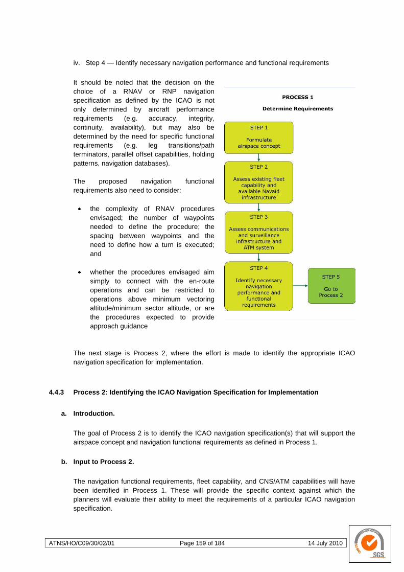
ATNS/HO/C09/30/02/01 Page 159 of 184 14 July 2010
iv. Step 4 — Identify necessary navigation performance and functional requirements
It should be noted that the decision on the
choice of a RNAV or RNP navigation
specification as defined by the ICAO is not
only determined by aircraft performance
requirements (e.g. accuracy, integrity,
continuity, availability), but may also be
determined by the need for specific functional
requirements (e.g. leg transitions/path
terminators, parallel offset capabilities, holding
patterns, navigation databases).
The proposed navigation functional
requirements also need to consider:
the complexity of RNAV procedures
envisaged; the number of waypoints
needed to define the procedure; the
spacing between waypoints and the
need to define how a turn is executed;
and
whether the procedures envisaged aim
simply to connect with the en-route
operations and can be restricted to
operations above minimum vectoring
altitude/minimum sector altitude, or are
the procedures expected to provide
approach guidance
The next stage is Process 2, where the effort is made to identify the appropriate ICAO
navigation specification for implementation.
4.4.3 Process 2: Identifying the ICAO Navigation Specification for Implementation
a. Introduction.
The goal of Process 2 is to identify the ICAO navigation specification(s) that will support the
airspace concept and navigation functional requirements as defined in Process 1.
b. Input to Process 2.
The navigation functional requirements, fleet capability, and CNS/ATM capabilities will have
been identified in Process 1. These will provide the specific context against which the
planners will evaluate their ability to meet the requirements of a particular ICAO navigation
specification.
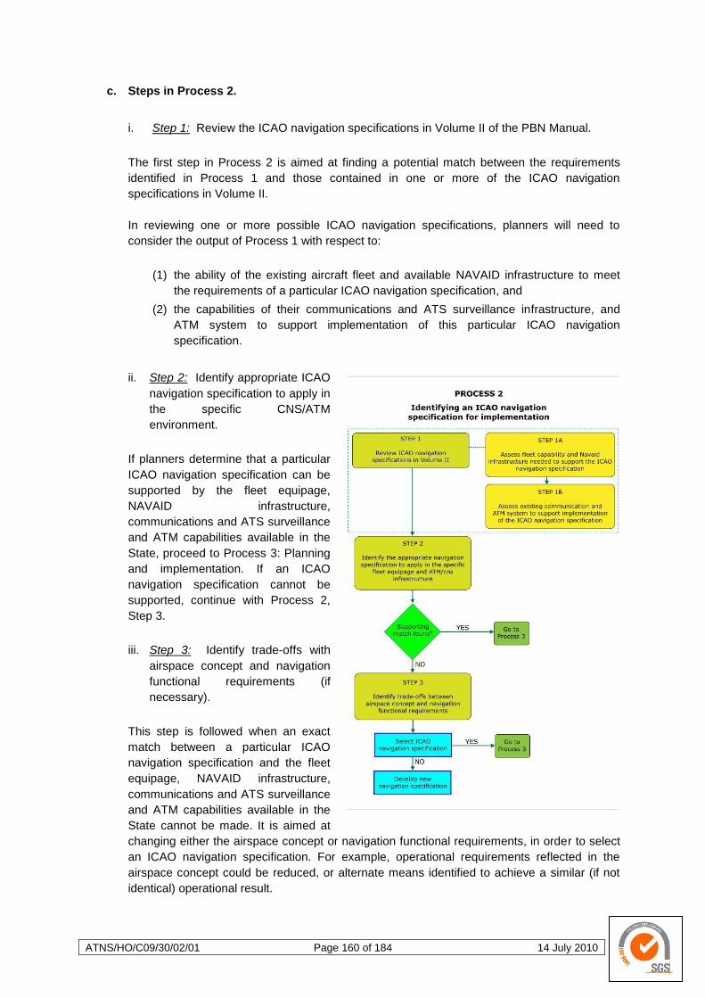
ATNS/HO/C09/30/02/01 Page 160 of 184 14 July 2010
c. Steps in Process 2.
i. Step 1: Review the ICAO navigation specifications in Volume II of the PBN Manual.
The first step in Process 2 is aimed at finding a potential match between the requirements
identified in Process 1 and those contained in one or more of the ICAO navigation
specifications in Volume II.
In reviewing one or more possible ICAO navigation specifications, planners will need to
consider the output of Process 1 with respect to:
(1) the ability of the existing aircraft fleet and available NAVAID infrastructure to meet
the requirements of a particular ICAO navigation specification, and
(2) the capabilities of their communications and ATS surveillance infrastructure, and
ATM system to support implementation of this particular ICAO navigation
specification.
ii. Step 2: Identify appropriate ICAO
navigation specification to apply in
the specific CNS/ATM
environment.
If planners determine that a particular
ICAO navigation specification can be
supported by the fleet equipage,
NAVAID infrastructure,
communications and ATS surveillance
and ATM capabilities available in the
State, proceed to Process 3: Planning
and implementation. If an ICAO
navigation specification cannot be
supported, continue with Process 2,
Step 3.
iii. Step 3: Identify trade-offs with
airspace concept and navigation
functional requirements (if
necessary).
This step is followed when an exact
match between a particular ICAO
navigation specification and the fleet
equipage, NAVAID infrastructure,
communications and ATS surveillance
and ATM capabilities available in the
State cannot be made. It is aimed at
changing either the airspace concept or navigation functional requirements, in order to select
an ICAO navigation specification. For example, operational requirements reflected in the
airspace concept could be reduced, or alternate means identified to achieve a similar (if not
identical) operational result.
ATNS/HO/C09/30/02/01 Page 161 of 184 14 July 2010
Planners should revisit the airspace concept and required navigation functions identified in
Process 1 to determine what trade-offs can be made, so as to implement a particular existing
ICAO navigation specification.
In most instances it will be possible to make sufficient trade-offs in the original airspace
concept or required navigation functions from Process 1 that an existing ICAO navigation
specification can then be selected. Once trade-offs have been made that will allow selection
of an ICAO navigation specification, proceed to Process 3: Planning and implementation.
However, if in the rare case that a State determines that it is impossible to make trade-offs in
its airspace concept and/or navigational functional requirements, the State would have to
develop a new navigation specification (discussed in the PBN Manual, Chapter 5, the ICAO
Doc. 9813).
4.4.4 Process 3: Planning and Implementation
a. Introduction.
The process described in this chapter is concerned with planning and implementing
Performance-Based Navigation. It follows upon completion of Process 1 and 2. See Inset for
a detailed discussion of some important considerations planners should keep in mind when
framing the implementation plan.
Inset — Implementation considerations In applying one of the ICAO navigation specifications for oceanic, remote continental and continental en-route operations as described in the PBN Manual Volume II, consideration should be given to the need for regional or multi-regional agreement. This is because connectivity and continuity with operations in adjoining airspace need to be considered to maximize benefits. For terminal and approach operations, the implementation of an ICAO navigation specification in the PBN Manual is more likely to occur on a single-State basis. Some TMAs are adjacent to national borders for which multinational coordination would likely be required. Where compliance with an ICAO navigation specification is prescribed for operation in an airspace or ATS routes, these requirements are to be indicated in the State‘s AIP. The decision to mandate a requirement for one or more ICAO RNAV or RNP specifications should only be considered after several factors have been taken into account. These include, but are not limited to:
the operational requirements of the airspace users (civil/military, IFR operations), as well as those of ANSPs;
regulatory requirements at both international and national levels;
the proportion of the aircraft population currently capable of meeting the specified requirements, and the cost to be incurred by operators that need to equip aircraft to meet the requirements of the navigation specification;
the benefits in terms of safety, capacity, improved access to airspace/airports or environment to be derived from implementing the airspace concept;
the impact on operators in terms of additional flight crew training;
the impact on flight crew in terms of workload; and
the impact on air traffic services in terms of controller workload and required facilities, (including automation and flight plan processing changes). Particular attention must be given to possible workload and efficiency impacts of operating mixed navigation environments.
ATNS/HO/C09/30/02/01 Page 162 of 184 14 July 2010
i. Step 1: Formulate safety plan.
The first step in Process 3 is the formulation of a safety plan for the PBN implementation.
Guidance for formulating a safety plan can be found in Safety Management Manual (SMM)
(ICAO Doc 9859). Depending on the nature of the implementation, this could be a State or
regional safety plan. Normally, such a plan would be developed together with an ANSP safety
bureau to the satisfaction of the regulatory authority. This safety plan details how the safety
assessment is to be accomplished for the proposed RNAV or RNP implementation.
ii. Step 2: Validate airspace concept for safety.
Validation of an airspace concept involves completing a safety assessment. From this
assessment, additional safety requirements may be identified which need to be incorporated
into the airspace concept prior to implementation.
Four validation means are traditionally used to validate an airspace concept:
airspace modelling;
fast-time simulation (FTS);
real-time simulation (RTS);
live ATC trials.
For simple airspace changes, it may be unnecessary to use all of the above validation means
for any one implementation. For complex airspace changes, however, FTS and RTS can
provide essential feedback on safety (and efficiency) issues and their use is encouraged.
Application of new navigation specifications can range from simple through major changes to
the airspace concept. All four types of validation are further discussed in the PBN Manual.
iii. Step 3: Procedure design.
A total system approach to the implementation of the airspace concept means that the
procedure design process is an integral element. Therefore, the procedure designer is a key
member of the airspace concept development team.
Procedure designers need to ensure that the procedures can be coded in ARINC 424 format.
Currently, this is one of the major challenges facing procedure designers. Many are not
familiar with neither the path & terminators used to code RNAV systems or the functional
capabilities of different RNAV systems. Many of the difficulties can be overcome, however, if
close cooperation exists between procedure designers and the data houses that provide the
coded data to the navigation database providers.
Once these procedures have been validated and flight inspected (see Steps 4 and 6), they
are published in the national AIP along with any changes to routes, holding areas, or airspace
structures.
The complexity involved in data processing for the RNAV system database means that in
most instances, a lead period of two AIRAC cycles is required (see PBN Manual Doc. 9813
Volume I Attachment B, Section 3 for more details).
ATNS/HO/C09/30/02/01 Page 163 of 184 14 July 2010
iv. Step 4: Procedure ground validation.
The development of a RNAV or RNP instrument flight procedure or ATS route follows a series
of steps from the origination of data through survey to the final publication of the procedure
and subsequent coding of it for use in an airborne navigation database. At each step of the
procedure design process, there should be quality control procedures in place to ensure that
the necessary levels of accuracy and integrity are achieved and maintained. These
procedures are detailed in PANS-OPS (Doc 8168), Volume II.
After designing the procedure and before a RNAV or RNP route or procedure is published,
PANS-OPS (Doc 8168) require that each procedure undergo a validation process. The
objective of validation is to:
(1) provide assurance that adequate obstacle clearance has been provided;
(2) verify that the navigation data to be published, as well as that used in the design of
the procedure, are correct;
(3) verify that all required infrastructure, such as runway markings, lighting, and
communications and navigation sources, are in place and operative;
(4) conduct an assessment of fly ability to determine that the procedure can be safely
flown; and
(5) evaluate the charting, required infrastructure, visibility and other operational factors.
Many of these factors can be evaluated, entirely or in part, during ground validation. Initial fly
ability checks should be conducted with software tools allowing the fly ability of the procedure
to be confirmed for a range of aircraft and in a full range of conditions (wind/temperature, etc.)
for which the procedure is designed. The verification of the fly ability of a RNAV or RNP
procedure can also include independent assessments by procedure designers and other
experts using specialised software or full-flight simulators. Fly ability tests using flight
inspection aircraft can be considered, but it must be borne in mind that this only proves that
the particular aircraft used for the test can execute the procedure correctly. This is probably
acceptable for the majority of less complex procedures. The size and speed of flight test
aircraft can seldom fully represent the performance of a fully loaded B747 or A340 and
therefore simulation is considered the most appropriate way to carry out the fly ability test.
Flight simulator tests should be conducted for those more complex procedures, such as RNP
AR APCH, when there is any indication that fly ability may be an issue. Software tools that
use digital terrain data (typically digital terrain elevation data (DTED) level 1 being required)
are available to confirm appropriate theoretical NAVAID coverage.
v. Step 5: Implementation decision.
It is usually during the various validation processes described above that it becomes evident
whether the proposed design can be implemented. The decision whether or not to go ahead
with implementation needs to be made.
Note: — If the available tools and/or quality of data used in Step 4 warrant, it may be
desirable to undertake Step 6 before a final implementation decision is taken.
ATNS/HO/C09/30/02/01 Page 164 of 184 14 July 2010
The decision on whether to go ahead with implementation or not will be based on certain
deciding factors. These include:
(1) whether the ATS route/procedure design meets air traffic and flight operations
needs;
(2) whether safety and navigation performance requirements have been satisfied;
(3) pilot and controller training requirements;
(4) whether changes to flight plan processing, automation, or AIP publications are
needed to support the implementation.
If all implementation criteria are satisfied, the project team needs to plan for execution of the
implementation, not only as regards their ―own‖ airspace and ANSP, but in cooperation with
any affected parties which may include ANSPs in an adjacent State.
vi. Step 6: Flight inspection and flight validation.
Flight inspection of NAVAIDs involves the use of test aircraft which are specially equipped to
gauge the actual coverage of the NAVAID infrastructure required to support the procedures,
arrival and departure routes designed by the procedure design specialist. Flight validation
continues the procedure validation process noted in Step 4. It is used to confirm the validity of
the terrain and obstruction data used to construct the procedure, and that the track definition
takes the aircraft to the intended aiming point, as well as the other validation factors listed in
Step 4.
Output from the above procedures may require the procedure design specialist to refine and
improve the draft procedures. The Manual on Testing of Radio Navigation Aids (ICAO Doc
8071) provides general guidance on the extent of testing and inspection normally carried out
to ensure that radio navigation systems meet the SARPs in Annex 10 — Aeronautical
Telecommunications, Volume I. PANS-OPS (ICAO Doc 8168), Volume II, Part 1, Section 2,
Chapter 4, Quality Assurance provides more detailed guidance on instrument flight procedure
validation.
vii. Step 7: ATC system integration considerations.
The new airspace concept may require changes to the ATC system interfaces and displays to
ensure controllers have the necessary information on aircraft capabilities. Considerations
arising from mixed equipage scenarios are discussed in the PBN Manual. Such changes
could include, for example:
(1) modifying the air traffic automation‘s flight data processor (FDP);
(2) making changes, if necessary, to the radar data processor (RDP);
(3) requiring changes to the ATC situation display; and
(4) requiring changes to ATC support tools.
There may be a requirement for changes to ANSP methods for issuing NOTAMS.
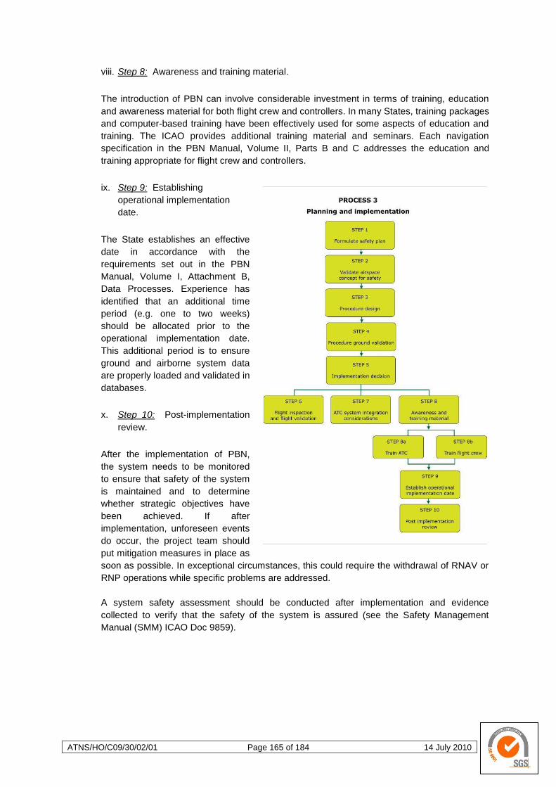
ATNS/HO/C09/30/02/01 Page 165 of 184 14 July 2010
viii. Step 8: Awareness and training material.
The introduction of PBN can involve considerable investment in terms of training, education
and awareness material for both flight crew and controllers. In many States, training packages
and computer-based training have been effectively used for some aspects of education and
training. The ICAO provides additional training material and seminars. Each navigation
specification in the PBN Manual, Volume II, Parts B and C addresses the education and
training appropriate for flight crew and controllers.
ix. Step 9: Establishing
operational implementation
date.
The State establishes an effective
date in accordance with the
requirements set out in the PBN
Manual, Volume I, Attachment B,
Data Processes. Experience has
identified that an additional time
period (e.g. one to two weeks)
should be allocated prior to the
operational implementation date.
This additional period is to ensure
ground and airborne system data
are properly loaded and validated in
databases.
x. Step 10: Post-implementation
review.
After the implementation of PBN,
the system needs to be monitored
to ensure that safety of the system
is maintained and to determine
whether strategic objectives have
been achieved. If after
implementation, unforeseen events
do occur, the project team should
put mitigation measures in place as
soon as possible. In exceptional circumstances, this could require the withdrawal of RNAV or
RNP operations while specific problems are addressed.
A system safety assessment should be conducted after implementation and evidence
collected to verify that the safety of the system is assured (see the Safety Management
Manual (SMM) ICAO Doc 9859).
ATNS/HO/C09/30/02/01 Page 166 of 184 14 July 2010
4.4.5 Guidelines for Development of a New Navigation Specification
a. Introduction.
In most instances, it will be possible to use an existing ICAO navigation specification from
PBN Manual Doc. 9813 Volume II to satisfy the navigation requirements for a State or
region‘s planned airspace concept. In the rare case that a State or region is not able to
complete Process 2 and select an ICAO navigation specification, the State or region would
have to develop a new navigation specification. In order to avoid proliferation of regional
standards, a new navigation specification would be subject to the ICAO review, and ultimately
be available for global application. There are guidelines in the PBN Manual that address this
situation.
Development of a new navigation specification should only be undertaken if it becomes
impossible to make acceptable trade-offs between the defined airspace concept and
navigational functional requirements that can be supported by a standard ICAO navigation
specification.
It should be recognised that development of a new navigation specification involves a
rigorous evaluation of navigation equipment and its operation. This will require even greater
involvement by airworthiness authorities than required in Process 2. While a considerable
amount of the preparatory work for development of a new navigation specification would
initially be undertaken as part of Processes 1 and 2, the State or region concerned must
undertake a full analysis at every step. Review and modifications to the work done in
Processes 1 and 2 may also need to be accomplished in whole or in part.
b. Steps for developing a new Navigation Specification.
i. Step 1: Feasibility assessment and business case.
When developing a new navigation specification, the question of the feasibility of establishing
a new navigation specification that can realistically be met by aircraft manufacturers and
operators, and achieving cost-effective implementation of that navigation specification, is
particularly important. It is necessary to undertake a feasibility assessment and to develop a
business case.
The business case assesses the benefits to be derived from the proposed airspace concept
and the cost of implementing a new navigation specification. The cost information will be
derived from the proposed functions included in the planned new navigation specification,
together with estimates of installation and certification costs.
It should be understood that the timescales from initial definition of a new requirement to
availability in new RNAV or FMS systems can be in excess of five to seven years.
Development from this point to one where the majority of the aircraft fleet operating in a given
airspace by natural (non-mandated) upgrading of the RNAV equipment can be in excess of
15 years. Thus, development of a new navigation specification normally involves using
navigation functional requirements already provided by manufacturers without the existence
of certification or operational approval.

ATNS/HO/C09/30/02/01 Page 167 of 184 14 July 2010
(1) Outline of a new navigation specification
The outline is a product of the business case and has to take due account of the functional
requirements needed to meet the airspace concept. It has to be produced with sufficient detail
to enable aircraft manufacturers to prepare cost estimates for the upgrades to RNAV systems
(including RNP systems).
ii. Step 2: Development of a navigation specification.
Contact should be made early with the ICAO in identifying the airspace concept that is to be
introduced and the foreseen need for a new navigation specification. The role of the ICAO in
this process will be to support the State or region in a detailed review of its requirements, in
order to ensure subsequent global acceptability of the new navigation specification.
Starting from the airspace concept which developers identified at the beginning of their PBN
implementation efforts, it will then be necessary to detail the requirements against which the
aircraft and its operation will ultimately be approved. In its coordinating role, the ICAO will be
able to identify other States or regions which may be in the process of developing a new
navigation specification with similar operational and/or navigational functions. In this situation,
the ICAO will support multi-State or multi-regional development of a new harmonised
navigation specification. Once the new navigation specification is complete, it will ultimately
be incorporated into the PBN Manual, Volume II.
Although the airspace concept and navigation functional requirements developed in Process
1 form the starting point of the development of a new navigation specification, it is likely that
these will need iterative refinement, in order to align them with the details of the new
navigation specification as it is being developed.
iii. Step 3: Identification and development of associated ICAO provisions.
The development of a new navigation specification may require the development of new
ICAO provisions, for example, procedure design (PANS-OPS (ICAO Doc 8168)) criteria or
ATM procedures. While these tasks are formally carried out by experts, a State(s) or region(s)
would be expected to identify changes that need to be introduced to enable the new
navigation specification and applications.
iv. Step 4: Safety assessment.
In accordance with the provisions included in the ICAO Annex 11 — Air Traffic Services and
PANS-ATM (ICAO Doc 4444), a full safety assessment of the new navigation specification
should be completed (see the Safety Management Manual (SMM) (Doc 9859). This safety
assessment is undertaken once the new navigation specification is sufficiently mature. See
PBN Manual, Volume II , Part A, Chapter 2 — Safety Assessment, for a more detailed
discussion of the necessary elements of safety assessment and risk modelling.
v. Step 5: Follow-up.
Where the above evaluation leads to the conclusion that the proposed new navigation
specification can be applied in the ATM environment, the State or region will be required to
formally notify the ICAO of the proposed application. The ICAO will take action to include the
new navigation specification into Volume II of the PBN manual.

ATNS/HO/C09/30/02/01 Page 168 of 184 14 July 2010
Upon completion of the new navigation specification development, the State or region would
then continue with Process 3: Planning and implementation.
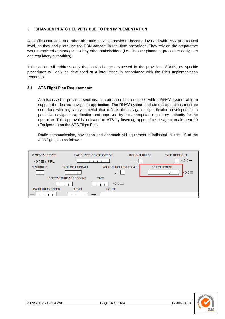
ATNS/HO/C09/30/02/01 Page 169 of 184 14 July 2010
5 CHANGES IN ATS DELIVERY DUE TO PBN IMPLEMENTATION
Air traffic controllers and other air traffic services providers become involved with PBN at a tactical
level, as they and pilots use the PBN concept in real-time operations. They rely on the preparatory
work completed at strategic level by other stakeholders (i.e. airspace planners, procedure designers
and regulatory authorities).
This section will address only the basic changes expected in the provision of ATS, as specific
procedures will only be developed at a later stage in accordance with the PBN Implementation
Roadmap.
5.1 ATS Flight Plan Requirements
As discussed in previous sections, aircraft should be equipped with a RNAV system able to
support the desired navigation application. The RNAV system and aircraft operations must be
compliant with regulatory material that reflects the navigation specification developed for a
particular navigation application and approved by the appropriate regulatory authority for the
operation. This approval is indicated to ATS by inserting appropriate designations in Item 10
(Equipment) on the ATS Flight Plan.
Radio communication, navigation and approach aid equipment is indicated in Item 10 of the
ATS flight plan as follows:
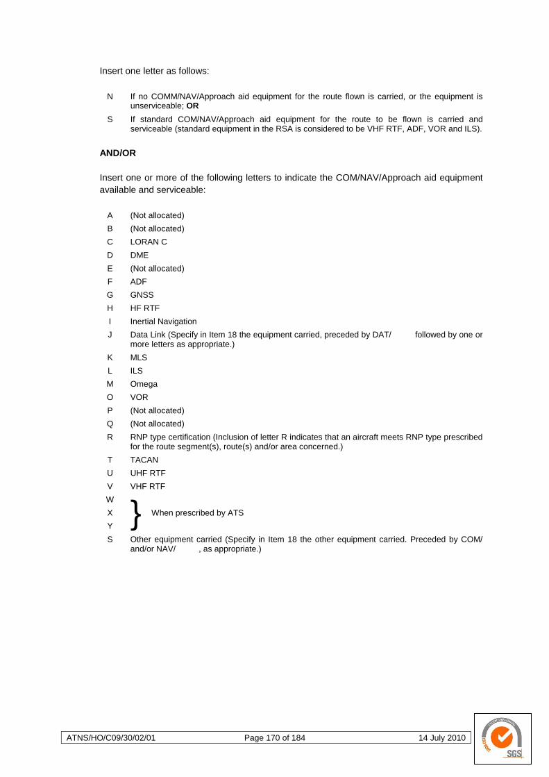
ATNS/HO/C09/30/02/01 Page 170 of 184 14 July 2010
Insert one letter as follows:
N If no COMM/NAV/Approach aid equipment for the route flown is carried, or the equipment is unserviceable; OR
S If standard COM/NAV/Approach aid equipment for the route to be flown is carried and serviceable (standard equipment in the RSA is considered to be VHF RTF, ADF, VOR and ILS).
AND/OR
Insert one or more of the following letters to indicate the COM/NAV/Approach aid equipment
available and serviceable:
A (Not allocated)
B (Not allocated)
C LORAN C
D DME
E (Not allocated)
F ADF
G GNSS
H HF RTF
I Inertial Navigation
J Data Link (Specify in Item 18 the equipment carried, preceded by DAT/ followed by one or more letters as appropriate.)
K MLS
L ILS
M Omega
O VOR
P (Not allocated)
Q (Not allocated)
R RNP type certification (Inclusion of letter R indicates that an aircraft meets RNP type prescribed for the route segment(s), route(s) and/or area concerned.)
T TACAN
U UHF RTF
V VHF RTF
W
} When prescribed by ATS X
Y
S Other equipment carried (Specify in Item 18 the other equipment carried. Preceded by COM/ and/or NAV/ , as appropriate.)
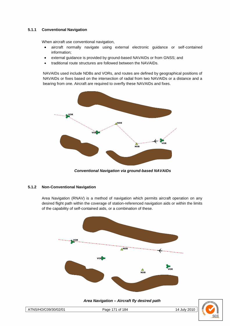
ATNS/HO/C09/30/02/01 Page 171 of 184 14 July 2010
5.1.1 Conventional Navigation
When aircraft use conventional navigation,
aircraft normally navigate using external electronic guidance or self-contained
information;
external guidance is provided by ground-based NAVAIDs or from GNSS; and
traditional route structures are followed between the NAVAIDs.
NAVAIDs used include NDBs and VORs, and routes are defined by geographical positions of
NAVAIDs or fixes based on the intersection of radial from two NAVAIDs or a distance and a
bearing from one. Aircraft are required to overfly these NAVAIDs and fixes.
Conventional Navigation via ground-based NAVAIDs
5.1.2 Non-Conventional Navigation
Area Navigation (RNAV) is a method of navigation which permits aircraft operation on any
desired flight path within the coverage of station-referenced navigation aids or within the limits
of the capability of self-contained aids, or a combination of these.
Area Navigation – Aircraft fly desired path
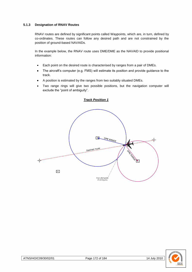
ATNS/HO/C09/30/02/01 Page 172 of 184 14 July 2010
5.1.3 Designation of RNAV Routes
RNAV routes are defined by significant points called Waypoints, which are, in turn, defined by
co-ordinates. These routes can follow any desired path and are not constrained by the
position of ground-based NAVAIDs.
In the example below, the RNAV route uses DME/DME as the NAVAID to provide positional
information:
Each point on the desired route is characterised by ranges from a pair of DMEs.
The aircraft‘s computer (e.g. FMS) will estimate its position and provide guidance to the
track.
A position is estimated by the ranges from two suitably situated DMEs.
Two range rings will give two possible positions, but the navigation computer will
exclude the ―point of ambiguity‖.
Track Position 1
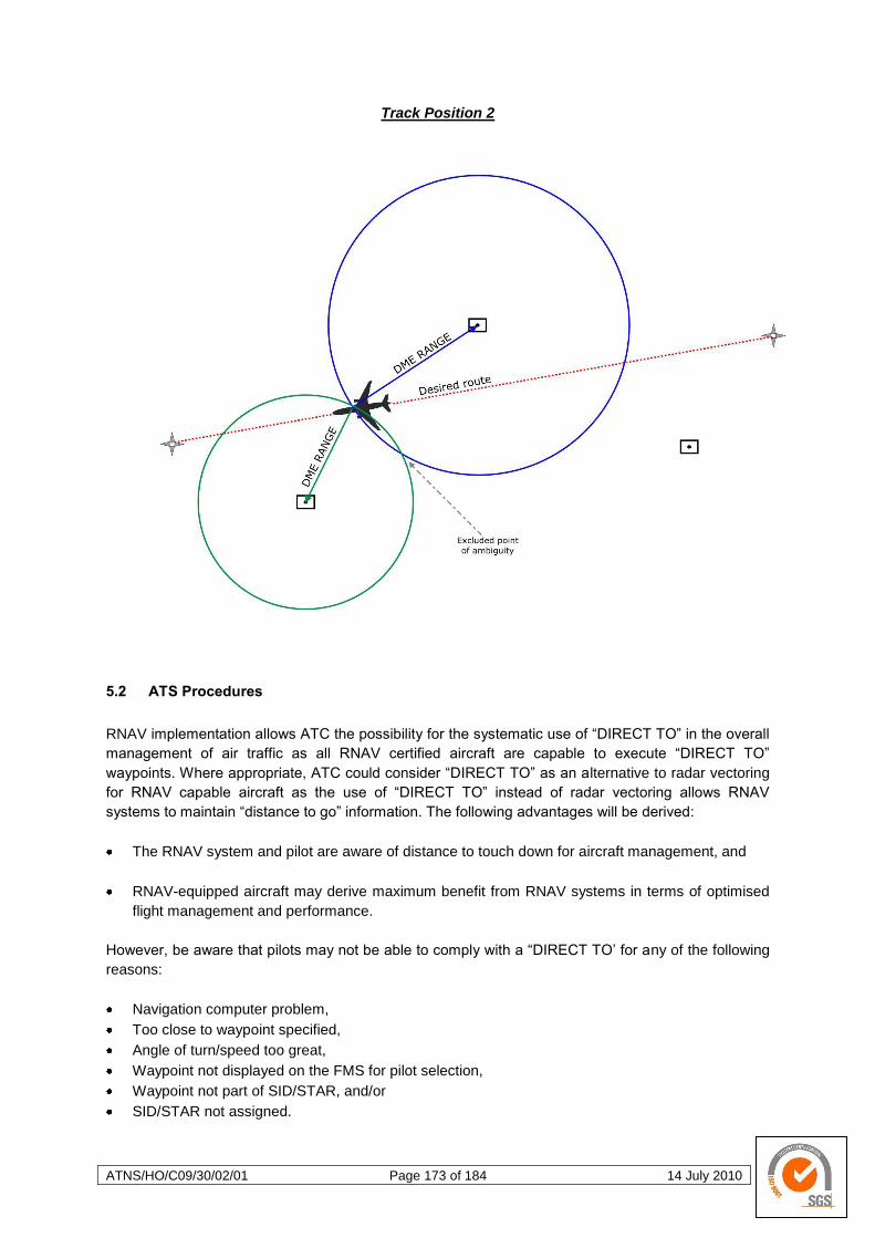
ATNS/HO/C09/30/02/01 Page 173 of 184 14 July 2010
Track Position 2
5.2 ATS Procedures
RNAV implementation allows ATC the possibility for the systematic use of ―DIRECT TO‖ in the overall
management of air traffic as all RNAV certified aircraft are capable to execute ―DIRECT TO‖
waypoints. Where appropriate, ATC could consider ―DIRECT TO‖ as an alternative to radar vectoring
for RNAV capable aircraft as the use of ―DIRECT TO‖ instead of radar vectoring allows RNAV
systems to maintain ―distance to go‖ information. The following advantages will be derived:
The RNAV system and pilot are aware of distance to touch down for aircraft management, and
RNAV-equipped aircraft may derive maximum benefit from RNAV systems in terms of optimised
flight management and performance.
However, be aware that pilots may not be able to comply with a ―DIRECT TO‘ for any of the following
reasons:
Navigation computer problem,
Too close to waypoint specified,
Angle of turn/speed too great,
Waypoint not displayed on the FMS for pilot selection,
Waypoint not part of SID/STAR, and/or
SID/STAR not assigned.

ATNS/HO/C09/30/02/01 Page 174 of 184 14 July 2010
If pilots are unable to comply, they will probably request radar vectors, but be aware that large turns
close to the waypoint or at high speed, may result in the aircraft overshooting the next leg.
5.2.1 Control Procedures
(FUTURE DEVELOPMENT)
a. Aerodrome (including Tower Control, Ground Control and Clearance Delivery)
b. Approach - Procedural, Radar and Automatic Dependant Surveillance (ADS)
c. Area - Procedural, Radar and ADS (including Flight Information Service & Oceanic)
d. Central Airspace Management Unit (CAMU) and the Briefing Office
5.2.2 Contingency Procedures
The pilot must notify ATC when the RNAV performance ceases to meet the requirements for
RNAV. The communication to ATC must be in accordance with the authorised procedures. In
the event of communication failure, the flight crew should continue with the flight plan in
accordance with the published ―lost communication‖ procedure.
The pilot must notify ATC of any loss of RNAV capability, together with the proposed course
of action. The loss of RNAV capability includes any failure or event causing the aircraft to no
longer satisfy the RNAV requirements of the route.
Where stand-alone GNSS equipment is used:
In the event that there is a loss of RAIM detection function, the GNSS position may
continue to be used for navigation. The flight crew should attempt to cross-check the
aircraft position, with other sources of position information, (e.g. VOR, DME and/or NDB
information) to confirm an acceptable level of navigation performance. Otherwise, the
flight crew should revert to an alternative means of navigation and advise ATC.
In the event that the navigation display is flagged invalid due to a RAIM alert, the flight
crew should revert to an alternative means of navigation and advise ATC.
(FUTURE DEVELOPMENT)
a. Aerodrome (including Tower Control, Ground Control and Clearance Delivery)
b. Approach - Procedural, Radar and Automatic Dependant Surveillance (ADS)
c. Area - Procedural, Radar and ADS (including Flight Information Service & Oceanic)
d. Central Airspace Management Unit (CAMU) and the Briefing Office
e. Contingency Procedures relating to Mach Number Technique

ATNS/HO/C09/30/02/01 Page 175 of 184 14 July 2010
5.3 Separation Minima
Vertical and horizontal (lateral and longitudinal) separation minima as per ICAO Doc 4444 and SA
CAA ATS Standards and Procedures Manual (as amended) are to be applied in the provision of ATS
to aircraft utilising PBN.
5.3.1 Longitudinal
(FUTURE DEVELOPMENT)
5.3.2 Lateral
(FUTURE DEVELOPMENT)
5.4 Mixed Equipage Environment
A mixed navigation environment introduces some complexity for ATS. From an ATC workload and
associated automation system perspective, the system needs to include the capability of filtering
different navigation specifications from the ATC flight plan and conveying relevant information to
controllers. For ATC, particularly under procedural control, different separation minima and route
spacing are applied as a direct consequence of the navigation specification.
Mixed navigation environments usually occur in one of three scenarios:
One RNAV or one RNP application has been implemented (but not as a mandate), and
conventional navigation is retained. An example of this would be if RNAV 1 were the declared
RNAV specification for a Terminal Airspace, with the availability also of procedures based on
conventional navigation, for those aircraft not RNAV 1 approved.
A ―mixed-mandate‖ is used within an airspace volume, usually en-route or oceanic/remote
procedural operations. For example, it is mandatory to be approved to a RNAV 1 specification for
operation along one set of routes, and Basic RNP 1 along another set of routes within the same
airspace;
A mix of RNAV and RNP applications is implemented in airspace, but there is no mandate for
operators to be able to perform them. Here again, conventional navigation could be authorised for
aircraft that are not approved to any of the navigation specifications.
Mixed navigation environments can potentially have a negative impact on ATC workload, particularly
in dense en-route and terminal area operations. The acceptability of a mixed navigation environment
to ATC is also dependent on the complexity of the ATS route or SID and STAR route structure and
upon availability and functionality of ATC support tools. The increased ATC workload normally
resulting from mixed mode operations has resulted in the need to limit mixed-mode operations to a
maximum of two types where there is one main level of capability. In some cases ATC has been able
to accept a mixed environment where 90% of the traffic is approved to the required navigation
specification; whereas in other instances, a 70% rate has been workable.
For these reasons, it is crucial that operations in a mixed navigation environment be properly
assessed in order to determine the viability of such operations.
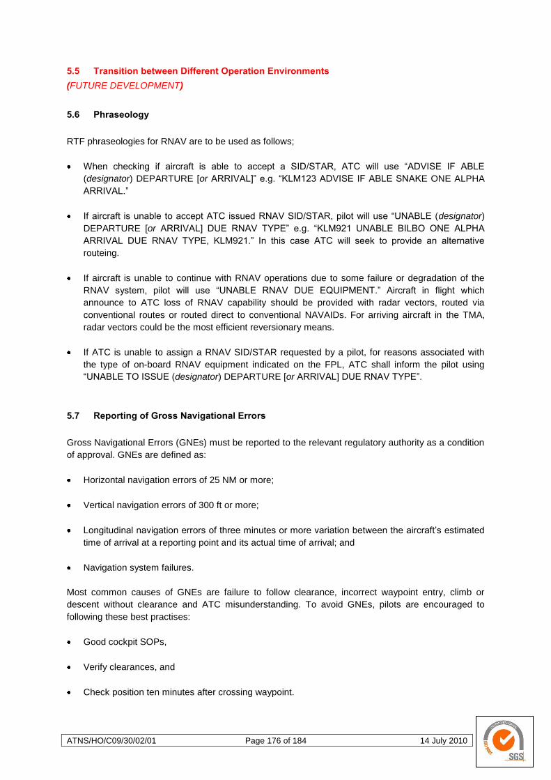
ATNS/HO/C09/30/02/01 Page 176 of 184 14 July 2010
5.5 Transition between Different Operation Environments
(FUTURE DEVELOPMENT)
5.6 Phraseology
RTF phraseologies for RNAV are to be used as follows;
When checking if aircraft is able to accept a SID/STAR, ATC will use ―ADVISE IF ABLE
(designator) DEPARTURE [or ARRIVAL]‖ e.g. ―KLM123 ADVISE IF ABLE SNAKE ONE ALPHA
ARRIVAL.‖
If aircraft is unable to accept ATC issued RNAV SID/STAR, pilot will use ―UNABLE (designator)
DEPARTURE [or ARRIVAL] DUE RNAV TYPE‖ e.g. ―KLM921 UNABLE BILBO ONE ALPHA
ARRIVAL DUE RNAV TYPE, KLM921.‖ In this case ATC will seek to provide an alternative
routeing.
If aircraft is unable to continue with RNAV operations due to some failure or degradation of the
RNAV system, pilot will use ―UNABLE RNAV DUE EQUIPMENT.‖ Aircraft in flight which
announce to ATC loss of RNAV capability should be provided with radar vectors, routed via
conventional routes or routed direct to conventional NAVAIDs. For arriving aircraft in the TMA,
radar vectors could be the most efficient reversionary means.
If ATC is unable to assign a RNAV SID/STAR requested by a pilot, for reasons associated with
the type of on-board RNAV equipment indicated on the FPL, ATC shall inform the pilot using
―UNABLE TO ISSUE (designator) DEPARTURE [or ARRIVAL] DUE RNAV TYPE‖.
5.7 Reporting of Gross Navigational Errors
Gross Navigational Errors (GNEs) must be reported to the relevant regulatory authority as a condition
of approval. GNEs are defined as:
Horizontal navigation errors of 25 NM or more;
Vertical navigation errors of 300 ft or more;
Longitudinal navigation errors of three minutes or more variation between the aircraft‘s estimated
time of arrival at a reporting point and its actual time of arrival; and
Navigation system failures.
Most common causes of GNEs are failure to follow clearance, incorrect waypoint entry, climb or
descent without clearance and ATC misunderstanding. To avoid GNEs, pilots are encouraged to
following these best practises:
Good cockpit SOPs,
Verify clearances, and
Check position ten minutes after crossing waypoint.
ATNS/HO/C09/30/02/01 Page 177 of 184 14 July 2010
5.8 RNAV STARs and SIDs
RNAV systems dynamically update the ―active‖ waypoints. As waypoints are passed, they are
removed from the ―active‖ waypoints list. Therefore, be aware that aircraft can have considerable
difficulty manoeuvring ―DIRECT TO‖ a waypoint which is considered by the RNAV system, to have
been passed. ATC should make use of ―DIRECT TO‖ instructions only for waypoints on the assigned
SID/STAR, and ―DIRECT TO‖ should only be used for waypoints ahead of the aircraft.
If the pilot has been cleared for a SID/STAR and ATC consequently have to issue a ‗DIRECT TO‖ a
waypoint that is part of the SID/STAR, the following applies:
The pilot selects the waypoint in the FMS,
The FMS and navigation display are updated maintaining all details of the route from the
―DIRECT TO‖ waypoint onwards, and
The aircraft continues with the SID/STAR after reaching the waypoint.
The aircraft is expected to meet level restrictions if published, if the cleared level makes this possible.
The aircraft is also expected to meet speed restrictions if published. Be aware however, that a
―DIRECT TO‖ could shorten track miles to the waypoint, which could have an impact on the aircraft‘s
ability to meet level and speed restrictions.
If the pilot has been cleared for a SID/STAR and ATC consequently have to issue a ‗DIRECT TO‖ a
waypoint that is not part of the SID/STAR, the following applies:
Waypoints not held in the navigational database are not to be manually inserted for aircraft
operations in the TMA.
It will take time for the pilot to retrieve the waypoint from the database.
The clearance for the SID/STAR is cancelled and previously loaded SID/STAR is dropped from
the RNAV system.
No further routeing is maintained or displayed.
The aircraft requires explicit routeing after the waypoint from ATC.
If no further explicit routeing information from ATC is received, the RNAV system will revert to
―present heading mode‖ after reaching the waypoint. That means that the aircraft will continue on
from the waypoint on the heading it is on when it arrives there, unless otherwise instructed.
Be aware that the aircraft reaction could be delayed and that this process is prone to error, therefore
ATC should rather consider the use of radar vectors if routeing away from a SID/STAR is required.
ATNS/HO/C09/30/02/01 Page 178 of 184 14 July 2010
Gra
phic
by E
uro
co
ntr
ol
Gra
phic
by E
uro
co
ntr
ol
5.8.1 Related Control Procedures
The use of RNAV does not change
existing ATC and pilot
responsibilities. It does not relieve:
Pilots of their responsibility to
ensure that any clearances are
safe in respect to terrain
clearance.
ATC of its responsibility to
assign levels which are at or
above established minimum
flight altitudes.
The pilot still remains responsible for
terrain clearance. When an IFR flight
is being radar vectored by ATC or is given a direct routeing off an ATS route, the radar
controller shall issue clearances such that the prescribed obstacle clearance exists, the pilot
must also ensure flight operations conform to published minimum flight altitudes and must
inform ATC of any inability to accept a clearance or instruction on the basis of terrain
clearance issues.
5.8.2 Radar Vectoring Techniques
If minimum radar vectoring altitudes are to be used by ATC as the basis for assigning levels
in conjunction with RNAV clearances/instructions, a Radar Minimum Altitude Chart should be
published to allow pilots to comply with their responsibilities with regard to terrain avoidance.
Note: Be aware that
RNAV ―DIRECT TO‖
instructions are not radar
vectors.
If ATC issues radar
vectors whilst an aircraft is
flying a RNAV SID/STAR,
ATC should be aware that
the pilot may require
considerable manipulation
of the RNAV system in
order to resume a
SID/STAR cancelled by
ATC, (i.e. the pilot may
have difficulty in
establishing the actual
sequence of active
waypoints, as a function of
the aircraft‘s position).
ATNS/HO/C09/30/02/01 Page 179 of 184 14 July 2010
Gra
phic
by E
uro
co
ntr
ol
Gra
phic
by E
uro
co
ntr
ol
For arriving aircraft, if radar vectoring is initiated, ATC should consider continuing with radar
vectoring until the aircraft intercepts the final approach aid, e.g. ILS. If radar vectoring is
initiated for departing aircraft, ATC should consider remaining with radar vectoring until the
aircraft is in a position to join the en-route ATS route structure, or issuing a ―DIRECT TO‖ the
last waypoint of the RNAV SID.
5.8.3 Open and Closed STARs
PBN makes it possible to design closed or open STARs. Although ―open‖ or ―closed‖ STARs
are not the ICAO expressions, these terms are increasingly common in use. The choice of
open or closed procedure needs to take account of the actual operating environment and
must take into account ATC procedures.
Open STARs provide
track guidance (usually)
to a downwind track
position from which the
aircraft is tactically
guided by ATC to
intercept the final
approach track. An open
STAR will require tactical
routeing instructions to
align the aircraft with the
final approach track. This
results in the RNAV
system being able to
descend only to the final
point on the procedure
and, where path
stretching is applied by
ATC, will impact the ability of the RNAV system to ensure a continuous descent profile.
Closed STARs provide track guidance right up to the final approach track whereupon the
aircraft usually intercepts the ILS. The closed STAR provides the pilot with a defined distance
to touch down thus supporting the RNAV system‘s execution of the vertical profile. Where
multiple arrival routes are
operated onto a single
runway, the closed
procedure can result in a
safety hazard should
ATC not be able to
intervene to prevent the
automatic turn onto final
approach towards other
traffic. Significantly,
however, closed STARs
can be designed and
published in a manner
that anticipates
alternative routeing to be
given by ATC on a

ATNS/HO/C09/30/02/01 Page 180 of 184 14 July 2010
Gra
phic
by E
uro
co
ntr
ol
tactical basis. These tactical changes may be facilitated by the provision of additional
waypoints allowing ATC to provide path stretching or reduction by the use of instructions
―direct to a waypoint‖. However, these tactical changes, needed to maximise runway capacity,
do impact on the vertical profile planned by the RNAV system
5.8.4 Altitude Constraints
(FUTURE DEVELOPMENT)
5.8.5 Descend/Climb Clearances
Three main categories of level information are used, i.e. minimum flight altitudes, cleared
levels and level restrictions.
Minimum flight altitudes (MFAs) can be considered as:
Minimum sector altitudes (MSAs)
Minimum radar vectoring altitudes (MRVAs)
Area minimum altitudes (AMAs)
Minimum flight altitudes published for segments of SIDs and STARs.
MFAs are calculated to ensure safe terrain clearances. It should be noted that currently it is
not mandatory to publish MRVAs, although it is recommended by the ICAO.
Cleared levels could be published as a written ―CLIMB TO/DESCEND TO (level)‖, ATC
expect aircraft to climb/descend to that level. These are mostly published as elements of SIDs
and have limited application for STARs. Explicitly cleared levels are issued by ATC on RTF
and override published cleared levels.

ATNS/HO/C09/30/02/01 Page 181 of 184 14 July 2010
Gra
phic
by E
uro
co
ntr
ol
Level restrictions are shown on charts in conjunction with waypoints where required, but do
not represent authorisation to climb/descend to that level, as it is published for purposes of
strategic airspace/traffic segregation. Pilots must comply with level restrictions to the extent
the cleared level makes it possible.
For arriving aircraft, published level restrictions, which are at or above the cleared level which
is in effect, shall be complied with. For departing aircraft, published level restrictions, which
are at or below the cleared level which is in effect, shall be complied with.
5.9 RNP Approach and Related Procedures
Waypoint speed restrictions may be published on charts in conjunction with selected waypoints where
required. ATC is free to cancel published speed restrictions at their own discretion. Explicit speed
restrictions override published ones. Be aware that adjusting speeds could have an impact on turn
performance (track) and vertical profiles.
5.10 Impact of Requesting a Change to Routing during a Procedure
(FUTURE DEVELOPMENT)
5.11 Fix/Waypoint Naming
In the ICAO Annex 11 and Doc 8168, the term ―waypoint‖ is only used to define ―RNAV routes and
flight paths of aircraft employing RNAV systems‖, while the term ―significant point‖ is used, in Annex
11, to describe a ―specified geographical location used in defining an ATS route or the flight path of an
aircraft and for other navigation and ATS purposes‖. It follows from this definition that all waypoints
are significant points, even when additional waypoints are established for RNAV procedures on, or
off-set from, the arrival/approach tracks, to allow the ATS provider to de-conflict and sequence RNAV
traffic.
ATNS/HO/C09/30/02/01 Page 182 of 184 14 July 2010
In many other documents, a waypoint is also described as a fix. This is especially the case in the
terminal area where the initial approach fix (IAF), the intermediate fix (IF), the final approach fix (FAF)
and the missed approach holding fix (MAHF) are commonly used terms. In order to avoid confusion,
the ICAO has decided to continue to use the terms IAF, IF, FAF and MAPt in both conventional and
RNAV instrument approach definitions.
As a general principal, the procedure designer should ensure that all RNAV waypoints are named and
that the published names are appropriate for use in the navigation database.
Navigation databases can hold waypoint names but usually operate with waypoint (fix) identifiers
which are five characters long, known as the 5 Letter Name Code (5LNC). The ICAO requires that all
significant points are identified by 5LNCs. However, waypoints marked by the site of a NAVAID,
should have the same name and coded designator as the NAVAID. NAVAIDs are usually annotated
with the associated three-letter designator on the aircraft displays but 5LNCs should be used where
three-letter designators are not available.
While the responsibility for issuing waypoint names lies with the ICAO regional office, individual
States should exercise great care when selecting new waypoint or NAVAID names to ensure that they
are not already in use.
The following table provides guidelines for naming waypoints:
Area of Application General Usage Name Type
En-route waypoints En-route environment
5-letter globally unique
pronounceable ICAO
name code
Final waypoint SID
Terminal airspace
procedures and transition
to en-route
5-letter globally unique
pronounceable ICAO
name code
Initial waypoint STAR
Terminal airspace
procedures and transition
from en-route
5-letter globally unique
pronounceable ICAO
name code
Waypoints common to more than one terminal
airspace or used in a procedure common to
more than one airport in a single terminal
airspace which are not used for en-route
Terminal airspace
procedures
5-letter globally unique
pronounceable ICAO
name code
Waypoints unique to an aerodrome, with a
properly assigned 4-letter location indicator,
used for terminal airspace procedures
(includes waypoints designated by the ATS
provider as requiring prominent display or as
having the function of an activation point)
Terminal airspace
procedures
5-letter globally unique
pronounceable ICAO
name code, or
5-digit alphanumeric
name code specific to
the terminal airspace
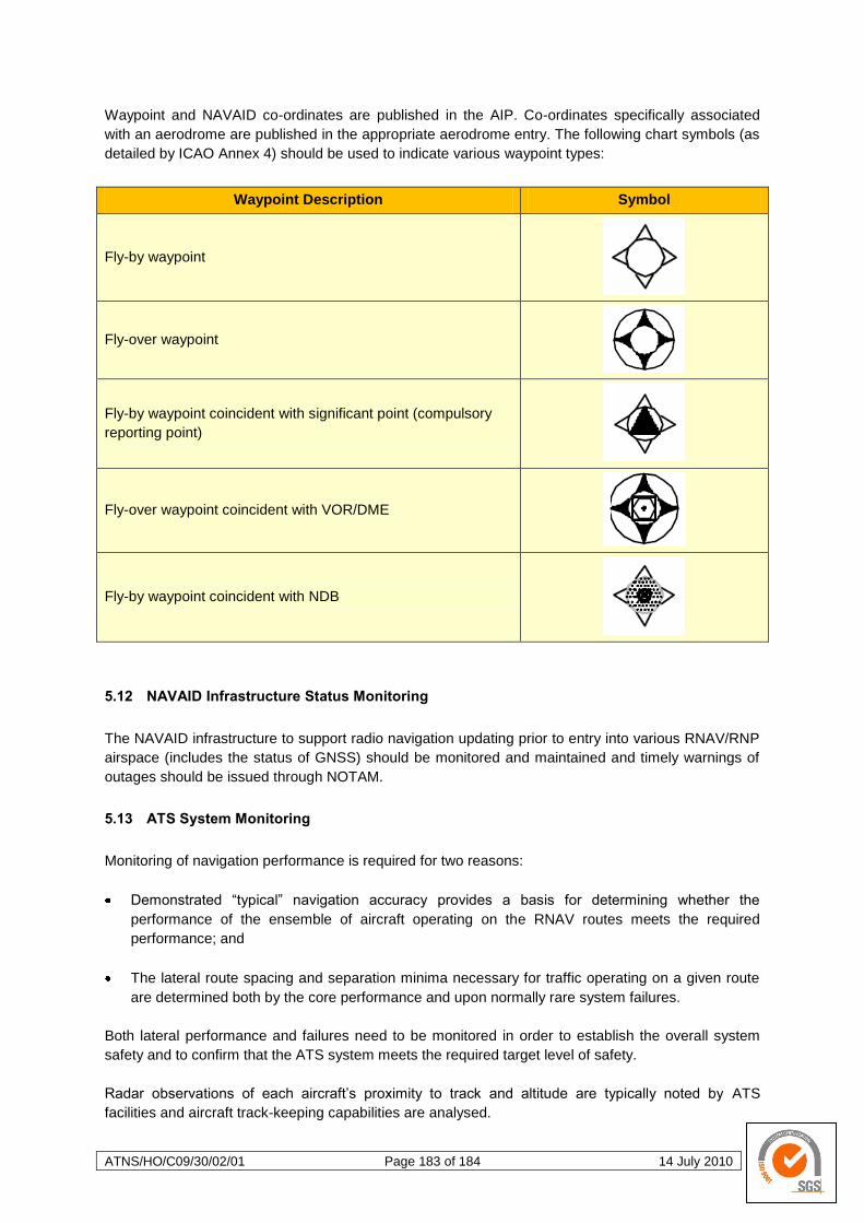
ATNS/HO/C09/30/02/01 Page 183 of 184 14 July 2010
Waypoint and NAVAID co-ordinates are published in the AIP. Co-ordinates specifically associated
with an aerodrome are published in the appropriate aerodrome entry. The following chart symbols (as
detailed by ICAO Annex 4) should be used to indicate various waypoint types:
Waypoint Description Symbol
Fly-by waypoint
Fly-over waypoint
Fly-by waypoint coincident with significant point (compulsory
reporting point)
Fly-over waypoint coincident with VOR/DME
Fly-by waypoint coincident with NDB
5.12 NAVAID Infrastructure Status Monitoring
The NAVAID infrastructure to support radio navigation updating prior to entry into various RNAV/RNP
airspace (includes the status of GNSS) should be monitored and maintained and timely warnings of
outages should be issued through NOTAM.
5.13 ATS System Monitoring
Monitoring of navigation performance is required for two reasons:
Demonstrated ―typical‖ navigation accuracy provides a basis for determining whether the
performance of the ensemble of aircraft operating on the RNAV routes meets the required
performance; and
The lateral route spacing and separation minima necessary for traffic operating on a given route
are determined both by the core performance and upon normally rare system failures.
Both lateral performance and failures need to be monitored in order to establish the overall system
safety and to confirm that the ATS system meets the required target level of safety.
Radar observations of each aircraft‘s proximity to track and altitude are typically noted by ATS
facilities and aircraft track-keeping capabilities are analysed.

ATNS/HO/C09/30/02/01 Page 184 of 184 14 July 2010
A process should be established allowing pilots and controllers to report incidents where navigation
errors are observed. If an observation/analysis indicates that a loss of separation or obstacle
clearance has occurred, the reason for the apparent deviation from track or altitude should be
determined and steps taken to prevent recurrence.