pbes full depth precast deck panel development and ... · pbes –full depth precast deck panel...
TRANSCRIPT

6/18/2015
1
Innovative Solutions for tomorrow’s transportation needs
PBES – Full Depth Precast Deck Panel
Development and ImplementationVickie Abalo, PE
Dennis Golabek, PE
Structures Design Office
Innovative Solutions for tomorrow’s transportation needs
Agenda• Introduction to EDC, ABC & PBES
• Pilot Project
• Precast Deck Panel Design
• Beam Design
• SRC Mock-UP
• Contract Documents
• Construction
• IBRD

6/18/2015
2
Innovative Solutions for tomorrow’s transportation needs
As part of FHWA's Every Day Counts (ABC) initiative, Prefabricated Bridge Elements and Systems (PBES) are used with goals to:
•Improve safety on the construction site, •Reduce onsite construction time, •Improve constructability, and •Improve quality.
In Florida:•Most common bridge type Prestressed Beam with C.I.P. Deck•Cast-In-Place Deck Significant portion of the Construction Time•Improved durability
Innovative Solutions for tomorrow’s transportation needs
Initial Design Considerations for Full Depth Precast Deck Panels
Mild Reinforced (Non-prestressed)
Transverse Prestressing
Future Widening Specialized labor/equipment Consider on-site or near-site casting
Deck Continuity over Intermediate BentsNo Expansion
JointsTransverse Joints will be less subjected to shrinkage & temperature effects
Longitudinal Post-Tensioning
Specialized labor/equipment Shop Drawings Required Inspections

6/18/2015
3
Innovative Solutions for tomorrow’s transportation needs
Pilot Project
Little River EB & WB Hurricane Creek EB & WB
US 90
Innovative Solutions for tomorrow’s transportation needs
Precast Deck Panels Development for US 90
Preliminary Analysis
- Different Girder Spacings (6, 9, 12 ft)
- Preliminary Models
- Thickened Edge Study
Design
- Flexure
- Stresses
- Construction Cases
Analysis
-Lifting – Different Support Conditions & Different Methods
- Leveling – Different Support Conditions
- Differential Creep – PT Panels
Refined Design
- Different Panel Thicknesses for PT Panels
- Stresses Due to Lifting
TestingStructural
Plan Sheets & Details

6/18/2015
4
Innovative Solutions for tomorrow’s transportation needs
Geometry
Var
ies
43’-1”
9’-0”Typ.3’-6.5”
OH
Innovative Solutions for tomorrow’s transportation needs
Panel Types• Mild Reinforcement – All Panels 8.5” Deck Thickness
• Type A – Typical Panel 8’-0” x 43’-1”• Type B – Edge Panel 7’-6” x 43’-1”• Type C – Edge Panel 5’-0” x 43’-1”
• Prestressed – Varying Deck Thickness Among Panel Type• Type D – Typical Panel 8’-0” x 43’-1” 8.5” Deck Thickness• Type E – Edge Panel 7’-6” x 43’-1” 10” Deck Thickness• Type F – Edge Panel 5’-0” x 43’-1” 10” Deck Thickness
Note:Reinforced Panels – Eastbound Bridges Prestressed Panels – Westbound Bridges

6/18/2015
5
Innovative Solutions for tomorrow’s transportation needs
Design & Design Methods• LOADS:
• Construction – Lifting & Leveling• Dead Load – Self Weight 8.5” (or 10”) Deck Thickness• Live Load – 20 psf (Leveling Only)• IM = 1.5
• Final • Dead Load – Self Weight 8” (or 9.5”) Deck Thickness & Future Wearing• Live Load – HL-93• IM = 1.33
• SUPPORT CONDITIONS:• Lifting 4 support points• Leveling & Final 5 support points
Innovative Solutions for tomorrow’s transportation needs
Design & Design Methods• DESIGN – Strength I & Service I:
• Construction – Lifting & Leveling Finite Element Model (FEM)*• Final
• Dead Load – Beam Line Model*• Live Load - AASHTO LRFD Appendix 4A, Deck Slab Design Table
• OVERHANG DESIGN – FDOT Structures Design Guidelines • Minimum Area of Steel
*Modeling was done using LUSAS and checked using RISA
6/18/2015
6
Innovative Solutions for tomorrow’s transportation needs
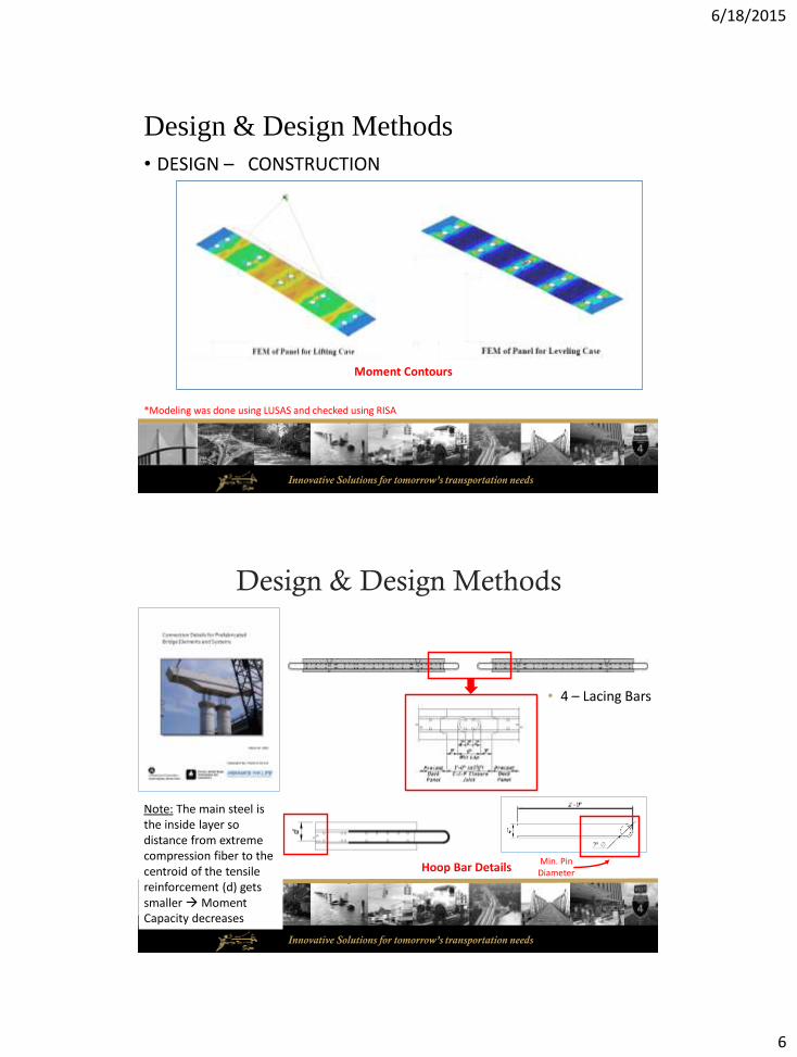
Design & Design Methods
• DESIGN – CONSTRUCTION
Moment Contours
*Modeling was done using LUSAS and checked using RISA
Innovative Solutions for tomorrow’s transportation needs
Design & Design Methods
• 4 – Lacing Bars
Hoop Bar DetailsMin. Pin
Diameter
Note: The main steel is the inside layer so distance from extreme compression fiber to the centroid of the tensile reinforcement (d) gets smaller Moment Capacity decreases

6/18/2015
7
Innovative Solutions for tomorrow’s transportation needs
Design & Design Methods
Panel TypeReinforcement for
Final Design
Reinforcement for Lifting
DesignReinforcement
Provided on Plans
Type A Typical Span#5 @ 6.5” T#5 @ 6.5” B
Add (10) #4 T (10) #4 & (15) #5 T(15) #5 B
8’-0”OH
#5 @ 3.25” T #5 @ 6.5” B
NA(25) #5 T(19) #5 B
Type B Typical Span#6 @ 7” T#6 @ 4” B
Add (2) #6 T (18) #6 T(25) #6 B
7’-6”OH
#6 @ 3.5” T#6 @ 4” B
NA(20) #6 T(23) #6 B
Type C Typical Span#6 @ 7” T#6 @ 4” B
Add (6) #6 T (15) #6 T(17) #6 B
5’-0”OH
#6 @ 3.5” T#6 @ 4” B
NA(15) #6 T(15) #6 B
DESIGN
Reinforced Panels
FINAL
Innovative Solutions for tomorrow’s transportation needs
Design & Design Methods
Panel Type Mild ReinforcementPrestressedSteel Design
Total Area of Prestressed
SteelArea of
Concrete
Area of Strands/Area of Concrete
Type D Typical Span(12) #4 T(12) #4 B (5) 0.5” Dia. T
(5) 0.5” Dia. B10 x 0.153 =
1.53 in2
8” x 8’-0” = 5.33 SF
1.53/5.33 = 0.29 in2/SF8’-0”
OH(18) #5 T(14) #5 B
Type E Typical Span(12) #7 T(12) #7 B (6) 0.5” Dia. T
(6) 0.5” Dia. B12 x 0.153 =
1.84 in2
10” x 7’-6” = 6.25 SF
1.84/6.25 = 0.29 in2/SF7’-6”
OH(12) #7 T(18) #7 B
Type F Typical Span(7) #7 T(7) #7 B (4) 0.5” Dia. T
(4) 0.5” Dia. B8 x 0.153 =
1.22 in2
10” x 5’-0” = 4.17 SF
1.22/4.17 = 0.29 in2/SF5’-0”
OH(8) #7 T
(13) #7 B
FINAL
Prestressed Panels

6/18/2015
8
Innovative Solutions for tomorrow’s transportation needs
Design & Design Methods
Specification Section DEV404:
Tension
Compression
Compression
Tension
Tension
Accounting for Differential Creep:• Panels Prestressed• Closure Joints Mild Reinf
Prestressed Panels
Innovative Solutions for tomorrow’s transportation needs
Does not include Barrier Steel
Detailing

6/18/2015
9
Innovative Solutions for tomorrow’s transportation needs
• Voids in the Panel• Shear Pockets• Leveling Device• Lifting Inserts• Keyway (Cover)• Scuppers in Closure Joint
• Barrier Steel
• Additional Steel for Lifting• Accommodate for Future Widening
• Develop Prestress Strands at Panel Ends
• Temperature & Shrinkage Steel Requirements • Hoop Bars & Lacing Bars for Closure Joint
• Longitudinal Steel Outermost Layer of Steel
• End Panel(s) (aka Thickened Slab End in SDG)
Detailing - Reinforcement Challenges
Innovative Solutions for tomorrow’s transportation needs
±½”
±½”
± ¼”
± ¼”
± 1”
± 1/8”
± 1/8”
± 1”
± ¼”
± 3/8”
± 1/16”
± 1/8” in 10 FT
Detailing –Tolerances
Precast Deck Panel
± ¼” Max
Closure Joint
6/18/2015
10
Innovative Solutions for tomorrow’s transportation needs
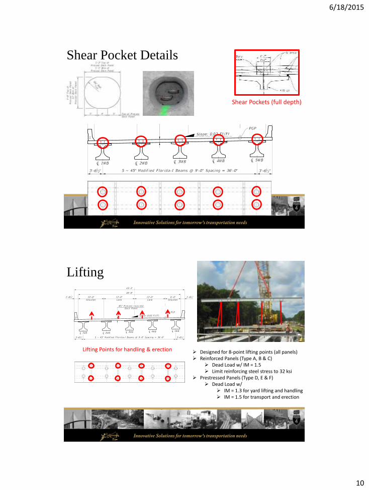
Shear Pocket Details
Shear Pockets (full depth)
Innovative Solutions for tomorrow’s transportation needs
Lifting
Lifting Points for handling & erection Designed for 8-point lifting points (all panels) Reinforced Panels (Type A, B & C)
Dead Load w/ IM = 1.5 Limit reinforcing steel stress to 32 ksi
Prestressed Panels (Type D, E & F) Dead Load w/
IM = 1.3 for yard lifting and handling IM = 1.5 for transport and erection

6/18/2015
11
Innovative Solutions for tomorrow’s transportation needs
Leveling
Leveling Devices
Cast Into Beam:Steel Plate on the Top of Girders placed at Leveling Bolt locations
Cast Into Panel:Square Washer,Pipe, & Nuts
Innovative Solutions for tomorrow’s transportation needs
Leveling – What exactly do we mean by leveling?
• Steps:• Survey top of beam elevations
• Preset Leveling Bolts to anticipated height
• Erect Panels within a span
• Adjust leveling devices to bring them to grade
• Survey top of beam after all panels have been placed & leveled.
• Submit information to Engineer for review
• If survey data does not produce required dead load distribution reset all panels with the span, resurvey and resubmit to the Engineer for review

6/18/2015
12
Innovative Solutions for tomorrow’s transportation needs
Closure Joints
1’-0” Cast in Place Closure Joints filled with Class II (Bridge Deck) w/ SRA Concrete on Site
Type A Epoxy on Keyway to bond fresh concrete to hardened concrete
KEYWAY
PDP = Precast Deck PanelSRA = Shrinkage Reducing Admixture
Innovative Solutions for tomorrow’s transportation needs
• Plans & Plan Notes:• Concrete Strength
• PDP Class II (Bridge Deck) = 4.5 ksi (Mild Reinforcement)
• PDP Class IV = 5.5 ksi, 4.4 ksi Release (Prestressed)
• C.I.P. Closure Joints Class II (Bridge Deck) w/ SRA = 4.5 ksi
• Structural Steel for Leveling Bolts• Bolt A193 B7 or F1554 Grade 55
• Pipe A53 Gr. B
• Washer A36 & Nut
• Reinforcement 60 ksi
• PT 0.5” Dia. Grade 270 Low Relaxation Strands
Specifications & Materials
PDP = Precast Deck PanelSRA = Shrinkage Reducing Admixture
For A193 Bolt – A194 Grade 2H For F1554 Bolt – A194 Grade 2H or A563 Grade A Hex

6/18/2015
13
Innovative Solutions for tomorrow’s transportation needs
Grouting Demonstration TestObjective of Test:• Demonstrate Grout Properties
• Adequacy of Equipment
• Forming Material
• Familiarize Job Site Personnel with Grouting Procedure
Conclusion:• Maintain the Grout at 70 degrees F to
meet the efflux requirements and to ensure a flowable /fluid mix
• Use 4 grout tubes (1 at each corner) for each haunch area.• Previous plan was only for 2 at high
point.
• Total percentage of voids 6%• The largest void was 2% of the total area.
• The haunch foam was hard to remove after the test Use less glue in the field.
Innovative Solutions for tomorrow’s transportation needs
Panels Installed

6/18/2015
14
Innovative Solutions for tomorrow’s transportation needs
Agenda - Continued• Introduction to EDC, ABC & PBES
• Pilot Project
• Precast Deck Panel Design
• Beam Design
• SRC Mock-Up
• Contract Documents
• Construction
• IBRD
Innovative Solutions for tomorrow’s transportation needs
Reinforced or Prestressed
8’-0” x 43’-1” (typ.)8’-0
”
Beam Design Superstructure Typical Section

6/18/2015
15
Innovative Solutions for tomorrow’s transportation needs
Beam Design MethodologyAASHTO LRFD BDS (5th edition)
C5.8.4.1: "Composite section design utilizing full-depth precast deck panels is not addressed by these provisions. Design specifications for such systems should be
established by, or coordinated with, the Owner.“
(Changed at the 2013 AASHTO SCOBS Annual Meeting)
Methods for Interface Shear Design
Equilibrium Forces
AASHTO LRFD 5.8.4
CIP Deck on PS Beams
Global Moment Capacity
AASHTO 6.10.10.4
CIP Deck on Steel Girders
Classical (elastic) Strength of Materials Method
VQ/I
Innovative Solutions for tomorrow’s transportation needs
Limit States
Strength I Load Combination
Cohesion and Steel
Strength II Load Combination
Consider only cohesion no slip under normal loading conditionsUse HL-93 live load
Cohesion and Friction Factors
Shear pocket and closure pour areas
CIP concrete slab on clean concrete girder surfaces, free of laitance with surface roughened to an amplitude of 0.25 in.
Other area based on a clean unroughened surface
K1 and K2 are also conservatively based on a clean unroughened surface.
Shear Pocket Spacing
AASHTO 5.8.4.2 limit of 24”
NCHRP Report 584
PCI journal article 'Composite Behavior of Precast Concrete Bridge Deck-Panel Systems‘ equation for the shear pocket spacing resulted in a maximum of 45 inches
Design Exception approved(changed in 2013)
Minimum Reinforcing
Due to wide flange of FIB
AASHTO 5.8.4.4 not met
Design satisfied two methodologies
Design Exception approved

6/18/2015
16
Innovative Solutions for tomorrow’s transportation needs
Horizontal Shear Reinforcing Layout
Uniform spacing of 3’ along the length of the beam
2’-6” 2’-6”8’-0”Typ.
3’-0” 1’-0”
CL Beam(TYP)
Innovative Solutions for tomorrow’s transportation needs
3 foot spacing
Strength IShear Resistance
Strength IIShear Resistance
Shear Plane ATop of Beam
(CIP deck with surface roughened)
Shear Plane BBottom of PDP
(normal weight concrete placed monolithically)
AASHTO 5.8.4.1-3
Shear Pocket andClosure Joint
Everywhere else

6/18/2015
17
Innovative Solutions for tomorrow’s transportation needs
Innovative Solutions for tomorrow’s transportation needs
SRC Mock-up

6/18/2015
18
Innovative Solutions for tomorrow’s transportation needs
Shear Pocket Blockout Forms
Leveling Device
PDP Forming PDP Lifting
Haunch Forming Material
Innovative Solutions for tomorrow’s transportation needs
Shear pocket with reinforcing protruding from beam
Grouting Operation
Leveling Bolt
Closure joint with hoop and
lacing bars

6/18/2015
19
Innovative Solutions for tomorrow’s transportation needs
Contract Documents
Plans
Specifications
Special Provisions
Developmental
Supplemental
Standard
Innovative Solutions for tomorrow’s transportation needs
Precast elements - fabricate, handle, store, ship and erect precast concrete bent caps and deck panels
Connections – attaching or joining precast elements with cast-in-place closure joints or grouted connections with details shown on the plans and in accordance with this Section
Fabricate precast elements in a precast plant, forming and curing in accordance with this Section and Section 400.
Fabricate prestressed precast deck panels in accordance with Section 450. Handle, store, ship, erect and complete construction of prestressed precast deck panels as precast deck panels in accordance with this Section while maintaining handling requirements as specified in Section 450.
Developmental Specifications 404Precast Concrete Elements for Bridge Construction

6/18/2015
20
Innovative Solutions for tomorrow’s transportation needs
Contents
404-1 Description
404-2 Materials
404-3 General
(Precast Placement Plan)
(Grout Demonstration Test)
404-4 Precast Bent Caps
404-5 Precast Deck Panel
(Transverse Closure Joints)404-6 Method of Measurement
404-7 Basis of Payment
Affected Specifications
Supplemental Specifications
400 Concrete Structures
450 Precast Prestressed Concrete Construction (prestressed PDP)
455 Structures Foundations
924 Admixtures for Concrete (SRA)
934 Non-Shrink Grout (Precision Grout)
Developmental Specifications 404Precast Concrete Elements for Bridge Construction
Innovative Solutions for tomorrow’s transportation needs
404-7 Basis of Payment
Item No. 404-1 Precast Bent Caps – per cubic yard
Item No. 404-5 Precast Deck Panel – per square yard
Item No. 404-6 Grout for Precast Deck Panel – per cubic yard
Item No. 404-7 Closure Joint for Precast Deck Panel – per linear foot
6/18/2015
21
Innovative Solutions for tomorrow’s transportation needs
Construction
BIDs
FIB Fabrication
PDP Fabrication
Haunch Forming
PDP Erection
PDP/Haunch Grouting
Transverse Closure Joint
Innovative Solutions for tomorrow’s transportation needs
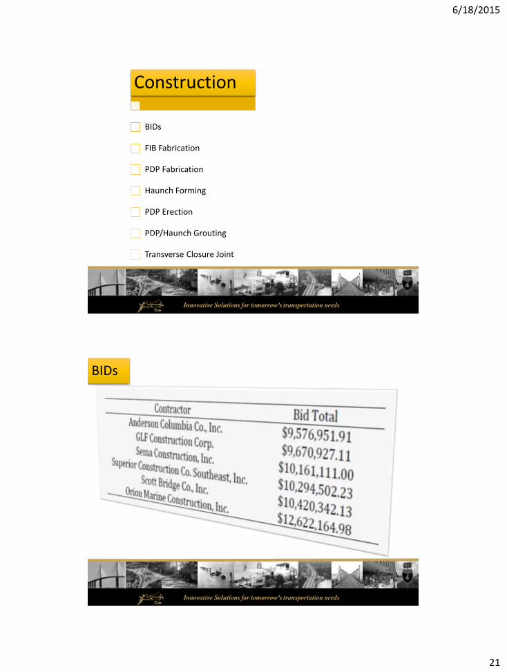
BIDs

6/18/2015
22
Innovative Solutions for tomorrow’s transportation needs
0
500
1000
1500
2000
2500
UN
IT P
RIC
E
ELEMENT
Tabulation of Bids for Precast Elements and Items
QTY5456 LF
QTY2331 SY
QTY2068 SY
QTY167 CY
QTY5084 LF
QTY181 CY
Precast Bent Caps
FIB 45 PDP Non-PS
PDP PS
Grout Closure JtConcrete
BIDs
Innovative Solutions for tomorrow’s transportation needs
FIB Fabrication

6/18/2015
23
Innovative Solutions for tomorrow’s transportation needs
PDP Fabrication
Innovative Solutions for tomorrow’s transportation needs
• Engineering Analysis Report (EAR) Cracking in the Precast Deck Panels – Non Prestressed
• Only 1 Panel required treatment• Epoxy Injection OR Methyl Methacrylate
PANEL TYPE A B C
No. of Panels 54 2 8
No Cracks 3 1 0
ISOLATED 44 0 6
OCCASIONAL 7 1 2
ISOLATED = Area of Cracking/Area of Panel < 0.0005%OCCASIONAL = 0.017% > Area of Cracking/Area of Panel > 0.0005%
PANEL TYPE WIDTH OF CRACK (in)
0.012 0.014 0.016 0.018
A 15 0 7 0
B 1 0 0 0
C 4 2 1 1
PDP Fabrication

6/18/2015
24
Innovative Solutions for tomorrow’s transportation needs
Haunch Forming
Innovative Solutions for tomorrow’s transportation needs
PDP Erection

6/18/2015
25
Innovative Solutions for tomorrow’s transportation needs
PDP/Haunch Grouting
Innovative Solutions for tomorrow’s transportation needs
Transverse Closure Joint

6/18/2015
26
Innovative Solutions for tomorrow’s transportation needs
Completed Bridge
Innovative Solutions for tomorrow’s transportation needs

6/18/2015
27
Innovative Solutions for tomorrow’s transportation needs
PBES – Full Depth Precast Deck Panel
Development and Implementation
Vickie Abalo, PE
Dennis Golabek, PE
Structures Design Office