a new precast concrete deck system for accelerated bridge ... · pdf filea new precast...
TRANSCRIPT

A New Precast Concrete Deck Systemfor Accelerated Bridge Construction
George Morcous1(&), Fouad Jaber2, and Jason Volz2
1 University of Nebraska-Lincoln, Omaha, NE, USA2 Nebraska Department of Roads, Lincoln, NE, USA
Abstract. Full-depth precast concrete deck systems have several advantagesover cast-in-place (CIP) concrete decks in bridge construction, such as improvedconstruction quality, reduced construction time and impact on traveling public,possible weight reduction, and lower life-cycle cost. This paper presents thedevelopment of a new full-depth precast concrete deck system for acceleratedbridge construction. The new system overcomes the drawbacks of existingsystems, such as the large number of panels, joints, and openings; complexity ofpanel production and erection; need for an overlay; and difficulty of post-tensioning and grouting operations. The developed deck system consists of full-width precast concrete deck panels that are 12 ft (3.6 m) long to minimize thenumber of panels and joints. Panels have covered pockets at 4 ft (1.2 m) spacingin each girder line for shear connectors. These pockets were designed to min-imize deck surface penetrations and eliminates the need for a deck overlay. Deckpanels are prestressed in both directions: pre-tensioned in the transverse direc-tion and post-tensioned in the longitudinal direction using a new approach thateliminates duct installation and grouting operations. These unique featuresenhance deck durability and improve its economic competitive with CIP con-crete decks. The paper also presents the construction sequence and a case studyfor the implementation of the new system.
1 Introduction
Precast concrete deck systems have several advantages over cast-in-place (CIP) con-crete decks commonly used in highway bridge construction. Examples are improvedquality and safety, reduced construction duration, and minimized maintenance cost.The quality of precast concrete decks is superior to CIP concrete decks as productionoccurs in a controlled environment eliminating the variability in environmental con-ditions, casting crews, and curing procedures. Moreover, shrinkage cracking in bridgedecks is minimized in precast systems due to the relatively small panel size, two-wayprestressing, and delayed composite action with supporting girders.
Composite full-depth precast concrete deck systems are commonly used because oftheir structural efficiency and reduced overall depth and cost of the superstructure.Existing full-depth full-width composite deck systems use either continuous openchannel along each girder line (trough) or closely spaced discrete openings (pockets) toaccommodate the shear connectors of the supporting girders. The troughs or pocketsare then field grouted and the deck surface need to be protected by an overlay similar to
© Springer International Publishing AG 2018H. Rodrigues et al. (eds.), Facing the Challenges in Structural Engineering,Sustainable Civil Infrastructures, DOI 10.1007/978-3-319-61914-9_18

CIP concrete decks, which increases construction duration and cost. In addition,transverse joints between adjacent deck panels are either conventionally reinforced orlongitudinally post-tensioned using embedded ducts. These transverse joints and/orducts have also to be field grouted, which complicate panel fabrication and erectionprocesses and, consequently, reduce the attractiveness of precast concrete deck systemsas an accelerated, economical, and durable alternative to CIP concrete decks.
Therefore, a new precast concrete deck system was developed to addresses theshortfalls of existing systems by achieving the following goals:
1. Simplify the fabrication of the supporting girders by using discrete clustered shearconnectors at 4 ft (1.2 m) spacing (the largest spacing allowed by AASHTO LRFD(2014)).
2. Fabricate the largest possible full-depth full-width precast concrete deck panel (12 ft(3.6 m) long) to minimize the number of panels and joints that need to be field cast.Also, no reinforcing bars and/or ducts are projecting out of the panel to void anypotential corrosion during the service life.
3. Use covered shear pockets in the panel with minimal penetrations to eliminate theneed for deck overlay. Lifting inserts can be located at the shear pockets.
4. Prestress the panel in both directions: transversely using pre-tensioning and lon-gitudinally using post-tensioning to control cracking and increase the service life ofthe deck.
5. Position post-tensioning strands underneath the deck soffit and above the girder topflange (i.e. haunch area) to eliminate the need for placing post-tensioning ductsinside the panels, threading strands through embedded ducts and across the joints,and grouting the ducts after post-tensioning, which are tedious and laboriousoperations.
The new precast concrete deck system was recently developed jointly by NebraskaDepartment of Roads (NDOR) and University of Nebraska-Lincoln (UNL). Severalanalytical and experimental investigations were conducted at UNL to evaluate thestructural performance and constructability of the new system. For more informationabout these investigations, refer to Morcous, et al. (2013) and Morcous, et al. (2015).Also, the new system was implemented to the construction of the Kearney East Bypassproject located in Kearney, NE in the summer of 2015. The next section presents theconstruction sequence of the new deck system. The following sections present theimplementation project.
2 Construction Sequence
The construction sequence of the new precast concrete deck panels is presented indetails in the following twenty steps and the corresponding sketches in Fig. 1:
1. Fabricate precast/prestressed concrete I-girders with shear connectors at 4 ft(1.2 m) spacing.
230 G. Morcous et al.

2. Fabricate full-depth full-width precast/prestressed concrete deck panels with cov-ered shear pockets and 4 in. diameter (100 mm) grouting holes, which will alsohost the lifting inserts.
Fig. 1. Construction steps of the new precast concrete deck system
A New Precast Concrete Deck System for Accelerated Bridge Construction 231

3. Erect all girders and check their alignment using a digital template to ensure thatshear connectors in all girders match the shear pockets in deck panels within thespecified tolerance.
Fig. 1. (continued)
232 G. Morcous et al.

4. Form, reinforce, and pour end and intermediate diaphragms up to the girder topflange.
5. Conduct shim shots on the edges and center of each girder line to determine theactual profile of the cambered girders prior to panel erection.
6. Attach the deck support system made of bent plates by welding them to the girdertop flange to achieve the desired deck elevation and a minimum haunch thicknessof 3 in. (75 mm).
7. Attach extruded polystyrene panels to the diaphragm concrete between girders tofill the gap between the deck panels and diaphragm concrete between girders.
8. Adjust the height of shear connectors (by cranking or cutting) to achieve thespecified embedment in the deck shear pockets (usually 5 in. (125 mm)).
9. Attach compressible material to the top of the deck support system to fill any gapsbetween the deck soffit and the deck support system.
10. Lay down post-tensioning strands longitudinally on top of each girder and threadthem through the end deviators embedded at the ends of each girder line.
11. Lay down negative reinforcement bars on the top flange of each girder over theintermediate support. Bars should be staggered and supported using chairs to avoidconflict with strands.
12. Erect each deck panel using the specified lifting points and place it on the decksupport system.
13. Use backer rod to fill the gaps between adjacent deck panels and clean/moist thejoint surfaces.
14. Pour flowable concrete/grout in the transverse joints between deck panels.
Fig. 1. (continued)
A New Precast Concrete Deck System for Accelerated Bridge Construction 233

15. Raise post-tensioning strands at the ends of each girder line to the mid-height of thedeck and thread them through the holes of the anchor plates.
16. Tension individual post-tensioning strands using mono-strand jack starting fromthe middle and moving symmetrically outward. Repeat this process for each girderline starting from the middle one and moving symmetrically outward.
17. Pour flowable concrete/grout to fill the gap between the deck soffit and girder topflange as well as shear pockets using the provided holes. Pouring should continueuntil the concrete overflow from every hole.
18. Form, reinforce, and pour approach slabs and the area around post-tensioningblocks.
19. Form, reinforce and pour the rails.
Fig. 2. (a) Shear connector assembly, and (b) installation of shear connectors
Fig. 3. Post-tensioning strand deviators
234 G. Morcous et al.

20. Grind the top surface of the finished deck up ½ in. (12 mm) to ensure a leveledridding surface.
3 Implementation Case Study: Kearney East Bypass Project
The Kearney East Bypass project is located in Kearney, NE over the US-30 and UnionPacific rail road tracks. The project consists of twin two-span bridges: a south boundbridge with cast-in-place concrete deck; and north bound bridge with precast concretedeck. Construction of the superstructure (girders, deck, and rail) of the two bridges wasdone concurrently starting in May 2015 and was completed in September of 2015.Each span is 166 ft (50 m) long and consists of five NU1800 precast/prestressedconcrete I-girders 71 in. (1.8 m) deep with 8 ft 6 in. (2.6 m) spacing. Bridge width is 41ft 8 in. (12.6 m) and has a 14o skew. Both cast-in-place and precast concrete decks are8 in. (200 mm) thick and have closed cast-in-place concrete rail. The following sec-tions summarize the fabrication of precast concrete girders and deck panels of the north
Fig. 4. (a) Shear pocket detail, and (b) wood forms used to position the pockets in the bed
Fig. 5. Forming and reinforcement of (a) typical panel, and (b) end panel
A New Precast Concrete Deck System for Accelerated Bridge Construction 235

bound bridge conducted by Coreslab Structures Inc. at the Plattmouth, NE plant, andtheir erection conducted by Hawkins Construction, Inc.
Fig. 6. Completed panels at the precast yard before shipping
Fig. 7. Deck support system and post-tensioning strands.
236 G. Morcous et al.

Fig. 8. Live load continuity reinforcement over intermediate support.
Fig. 9. Erection of precast concrete deck panels.
A New Precast Concrete Deck System for Accelerated Bridge Construction 237

3.1 Girder Production
The only two differences in the production of the bridge girders between the CIP andprecast concrete deck systems are: (1) shear connectors; and (2) post-tensioning stranddeviators. Shear connectors for the precast concrete deck system consisted of two 1.25in. (32 mm) diameter A193 Grade B7 coil rods spaced at 4 ft (1.2 m) along the girder.Each connector was made in an assembly of two rods, four nuts and washers, one plate,and 4 #6 (No. 19) bars as shown in Fig. 2a. Connectors are placed in the girder weband attached to pre-slotted steel angles, shown in Fig. 2b, to hold them and ensure thatspacing is within the specified tolerance. The portion of each rod embedded in thegirder was greased to allow cranking it up later to adjust the height as needed.Post-tensioning strand deviators are similar in concept to the hold-down devices used indepressing pre-tensioning strands. They are placed at the abutment end of each girderto depress deck post-tensioning strands from their end location (i.e. middle of the deckthickness) to be under the deck soffit (i.e. haunch area). Figure 3 shows the
Fig. 10. Placing concrete for transverse joints.
Fig. 11. Post-tensioning strands and anchor block.
238 G. Morcous et al.
custom-made post-tensioning strand deviators for 12-0.6 in. (15.3 mm) diameterpost-tensioning strands.
3.2 Deck Production
The 12 ft (3.6 m) long, 41 ft 8 in. (12.6 m) wide, and 8 in. (200 mm) thick precastconcrete deck panels were produced using the same prestressing bed used for precastconcrete sandwich wall panel production. A total of 26 typical panels were produced ata rate of four panels at a time, in additional to two special end panels that haveanchorage blocks. Each panel has a total of 15 pockets (3 pockets for each girder line)for shear connectors. Each pocket consists of HSS 16 � 8 � ¼ (400 � 200 � 6) with4 #5 (No. 16) bars welded to each side as shown in Fig. 4a. Custom-made lifting insertswere added to some of the pockets to be used in panel handling and eliminate the needfor additional penetrations to the panel surface. All pockets were galvanized andpositioned precisely by gluing wooded sheets to the bed as shown in Fig. 4b. All panelshave 14o shew angle and were pre-tensioning transversely using 6-0.6 in. (15.3 mm)diameter strands at the level of the top reinforcement and 6-0.5 in. (12.5 mm) diameterstrands at the level of bottom reinforcement. Styrofoam was used to form the 4 in.(100 mm) diameter grouting holes and anchorage blocks, while plywood was used toform the shear keys along the panel edges. Figures 5a and b show the forming andreinforcement of a typical panel and end panel respectively. All panels were madeusing the conventional bridge deck concrete mix but with a specified 28-day com-pressive strength of 6,000 psi (41 MPa) and release strength of 3,500 psi (24 MPa).Figure 6 shows the completed panels.
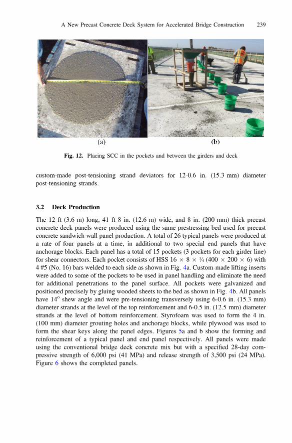
Fig. 12. Placing SCC in the pockets and between the girders and deck
A New Precast Concrete Deck System for Accelerated Bridge Construction 239

3.3 Girder and Panel Erection
Girders were shipped and erected similar to conventional bridge construction. Slightlymore attention was given to positioning girders in their exact locations. After placingend and intermediate diaphragms, galvanized steel bent plates were welded to the metaltabs embedded in the girder top flange according to girder profile data obtained fromshim shots and specified deck profile and haunch thickness. This deck support systemalso works as side forms for grouting the haunch area later. Therefore, a compressiblesealing strip was attached to the top of the bent plates and caulking was used at thebottom of the bent plates, as shown in Fig. 7, to prevent grout leakage. Figure 7 alsoshows the 12-0.6 in. diameter post-tensioning strands laid over the top flange for eachgirder line and through the end deviators. Figure 8 shows the 10 #8 (No. 25) Grade 60(420 MPa) bars installed over the girder top flange (i.e. in the haunch area) over theintermediate pier to provide live load continuity and resist negative moment. Figure 8also shows the greased rods of the shear connectors cranked up to the calculatedelevation that achieves the specified embedment of each rod into the shear pocket.Panel erection was done using a single crane and the 8 lifting inserts embedded in thepockets as shown in Fig. 9a. The installation of the first panel occurred at the pierlocation as shown in Fig. 9b and remaining panels were then installed in both direc-tions until end panels were installed at the abutment locations. Installation duration wasapproximately 30 min for the first panel and 20 min for each panel thereafter.
Figure 10 shows one of the transverse joints between deck panels and the placingof conventionally vibrated concrete at the joint using a bucket and shovel. The concretemix was the same one used in panel production. Transverse joints were coveredimmediately with curing compound then later with wet burlap. Once the joint concreteachieved the specified compressive strength, post-tensioning was conducted using amono-strand jack from one end as shown in Fig. 11 to apply 500 psi (3.5 MPa) stressacross the deck section. All the 60 strands were tensioned in a symmetrically alter-nating manner to minimize eccentricity effects on the deck. Measured elongations of allstrands were with ±5% of the predicted elongation.
The grouting of the haunch, shear pockets, and anchor blocks were conductingusing highly flowable and high strength self-consolidating concrete (SCC). The mix
Fig. 13. Final deck surface: before grinding (a), and after grinding (b)
240 G. Morcous et al.

had a nominal maximum size of 3/8 in. (10 mm) limestone aggregate, specifiedstrength of 8,000 psi (55 MPa), and slump flow of 28 in. (700 mm) as shown inFig. 12a. SCC was pumped from one location (at the bridge pier) to the 4 in. (100 mm)diameter grouting holes on the deck surface using the apparatus shown in Fig. 12b(hopper, bucket, and inverted cone). SCC was placed from one grouting hole andflowed in both directions until overflowed from the adjacent holes, which were coveredwith sand-filled buckets before moving to the next grouting hole. This process ensuredcomplete filling of haunch and pockets and took 1 h per girder.
Figure 13a shows the deck surface after grouting and curing of SCC, whileFig. 13b shows the final deck surface after placing the rail and grinding the decksurface up to ½ in. (13 mm). The grinding operation tool 1 day, which is similar to thetexturing operation done on the cast-in-place deck. The final deck surface will not havean overlay and will be monitored for any signs of deterioration in the next few years. Itshould be noted that few transverse cracks were observed at the transverse joints beforedeck post-tensioning. These cracks were closed after post-tensioning was applied andthe final deck surface does not have any cracking. Also, there is no clear discolorationin the final deck surface between precast concrete and CIP concrete used in groutingthe transverse joints and shear pockets.
Acknowledgment. The research project was sponsored by Nebraska Department of Roads(NDOR). The contributions of NDOR engineers and staff under leadership of Mark Traynowiczare highly appreciated. Thanks to Todd Culp, Andy Flanagan, and Lance Overland fromCoreslab Structures, Inc.; Jim Gregory and Jessie Ridder from Hawkins Construction, Inc.; andAfshin Hatami, Micheal Asaad and Raed Tawadrous from UNL.
References
American Association of State Highway and Transportation Officials (AASHTO):AASHTO LRFD Bridge Design Specifications: Customary U.S. Units, Washington, D.C.,7th Edition (2014)
Morcous, G., Tadros, M.K., Hatami, A.: Implementation of precast concrete deck systemsNUDECK (2nd generation). Technical report M323, Nebraska Department of Roads (NDOR)(2013)
Morcous, G., Hatami, A., Asaad, M.: Evaluating the constructability of NUDECK precastconcrete deck panels for kearney bypass project. Technical report M336, NebraskaDepartment of Roads (NDOR) (2015)
A New Precast Concrete Deck System for Accelerated Bridge Construction 241