part iii - wur
TRANSCRIPT

PART III - CASE STUDIES
447
PART IIICASE STUDIES
China 27-7-2004.qxp 9-2-2005 14:25 Pagina 447

PART III - CASE STUDIES
448
China 27-7-2004.qxp 9-2-2005 14:25 Pagina 448

PART III - CASE STUDIES
449
Preamble
Part III presents salient features of the history, development and present practices of theimplementation of subsurface drainage in China, Egypt, India, The Netherlands and Pakistan.Although subsurface drainage is practised in many more countries a selection of only these fivecountries has been made on the basis of availability of up to date information. Furthermore thesefive countries are considered to be representative for various climate regions and institutionalsettings. The most relevant experiences in the countries have already been used to compile PartI and Part II. These practices are not repeated in the case studies, the presented information isto highlight that each country has its specific physical and institutional conditions. For each andevery country, technical and organisational arrangements have to be tailor-made to fit for thespecific local conditions, straightaway copying practices and experiences from one country toanother is no option. Thus the case studies are presented as a reference for the reader and areconsidered useful for those who want to start subsurface drainage on a local or national scale.
Countries were pipe drainage is or has been practised
AlgeriaAustraliaBelgiumChiliCanadaChinaColombiaDenmarkEgyptEthiopiaFinland
FranceGermanyHungaryIndiaIraqIranItalyJordanKorea (South)MexicoMorocco
PolandPortugalTurkeyThe NetherlandsPakistanPeruRumaniaRussiaSenegalSlovakiaSpain
SyriaTaiwanCzech RepublicTunisiaUnited States of AmericaUzbekistanUnited KingdomYugoslavia (former)
China 27-7-2004.qxp 9-2-2005 14:25 Pagina 449

PART III - CASE STUDIES
450
China 27-7-2004.qxp 9-2-2005 14:25 Pagina 450

PART III - CASE STUDIES
451
Case Study - China
China 27-7-2004.qxp 9-2-2005 14:25 Pagina 451

PART III - CASE STUDIES
452
China 27-7-2004.qxp 9-2-2005 14:25 Pagina 452

PART III - CASE STUDIES
453
Case Study - China1
1 Introduction
More than half of the cultivated land in China is affected by either waterlogging and/or salinity.Consequently waterlogging and salinity are important issues in China, even more so since thenatural conditions of the country are such that only one third of the land is suitable for agri-culture. Salinity problems occur in 13 to 14 million ha or 14% of the total cultivated land (around97 million ha) and waterlogging in 24 million ha or 25% of the cultivated areas2. In the northernparts of China, which has a rainfall deficit, about 50% of the cultivated lands are irrigated. Irri-gation induced salinity occurs in more than 11 million ha or 23 % of these irrigated lands.
Modern drainage techniques in combination with traditional methods can potentially solve mostof the waterlogging and salinity problems at field level. Since the 1960's major improvementshave been realised by implementing large scale open drainage systems, (tube)well drainagesystems and intensifying research and experiments with pipe drainage on pilot and practicalscale.
2 Distribution of areas with drainage problems
The distribution over the country of the areas suffering from drainage problems can be sum-marised as follows (Figure 1 and 2):
• No obvious drainage problems occur in the western part of China: the mountainous areasof and around the Qinghai-Tibet plateau;
• The plateaus and plains and river valleys in the arid and semi arid north and northwest haveconsiderable salinity problems often combined with alkalinity;
• The river plains in the North East that form a delta area (Three River or Sanjiang Plain) havehigh groundwater tables but no significant salinity;
• The North China Plain, located in the east (Huang-Huai-Hai Rivers Plain) is affected by acombination of high groundwater tables, saline groundwater and consequently soil salinity,in some areas combined with alkalinity. Large areas in the Yellow River Delta, an econo-mically important part of the North China Plain, are either in direct or indirect contact withthe sea and hence have saline groundwater and suffer from saline soils;
1 This chapter has been written in close cooperation with Prof Fang Sheng of the Hebei Institute of Hydrotechnics,
dr. Ding Kunlun of the IWHR, Engineer Lin Chi, retired from the CAAERP, and Mr. Zhuang Huijiang of Municipal
Government of Dongying Shandong. Use has been made of the Chinese publications of En. Yang Cheng Qu retired
from the Xinjiang Agricultural Industrial and Trade Corporation (XAITC) and the experience of Mr.He Gang formerly
of the (XAITC) and Mr. Zheng Cunhu of the Kingchuan Company Dong Ying Shandong.2 Irrigation and Drainage in China, Ministry of Water Resources and Electric Power, 1987.
China 27-7-2004.qxp 9-2-2005 14:25 Pagina 453

PART III - CASE STUDIES
454
• The Yangtze Delta and the Pearl River Delta suffer from waterlogging and salinity pro-blems. Salinity is more prevalent in the coastal areas, but because of the high rainfall it isless serious than in the North China Plain. Water logging is more prominent land inwards;
• The inland river plains of the huge Yangtze River basin have considerable, sometimesseasonal, waterlogging problems;
• The river plains of the Pearl River basin have the same considerable, sometimes seasonal,waterlogging problems. Since most of the areas in this basin are traditional rice growingareas, waterlogging does not always seriously impede crop growth.
3 Historical developments
3.1 Drainage in ancient times
The Chinese population has been struggling with waterlogging and salinity control throughout itshistory. The earliest records of a search for solutions date from around 1000 years B.C. Overthe years ingenious solutions have been found to control waterlogging and salinity, among which
Water logged area
NORTH-WEST CHINA
INNER MONGOLIA
QINGHAI-TIBETANPLATEAU
NORTH-EASTCHINA
NORTH CHINA
SOUTH CHINA
YANGTZE RIVERVALLEY
SOUTH-WESTCHINA
Beijing
Shanghai
QinLing Ridge-Huai He River Line
SICHUANBASIN
Lhasa
Kunlun Shan Qilian Shan
Gre
atW
allLin
e
Nan Ling Mountain Range Line
Guangzhou
QAIDAM PENDI
Da H
inggan L
ing
Figure 1 Waterlogged areas in China
China 27-7-2004.qxp 9-2-2005 14:25 Pagina 454

PART III - CASE STUDIES
455
of course is leaching through rice growing. Open drains have been built to convey the surpluswater to rivers and seas. In inland areas drainage canals have been built and rivers have beendeepened to allow disposal of drainage water and consequently lowering of water tables.
Salt management has been practiced by traditional methods, for example:• Building up the soil level by so called "warping". Warping is a technique consisting of filling
manmade basins with silt-loaded irrigation water and then draining off the water once thesilt has settled. In this way a new salt-alkali free soil layer is deposited on top of thesalinised land, which allows temporarily cultivation in a relatively salt free environment;
• "Stone mulching" to reduce capillary rise and to prevent secondary salinsation to some ex-tend;
• Land forming/levelling, a method to concentrate the capillary rise of saline groundwaterin predetermined areas, so that crops can be planted in areas where no or limited second-ary salinzation occurs;
• Crop rotations, where rice crops are alternated with dry-foot crops, thereby allowing leach-ing of salts accumulated in the soil during the growing season of the dry-foot crops andpercolation of water from the rice crops;
Figure 2 Saline-alkali areas in China
Saline-alkali area
NORTH-WEST CHINA
INNER MONGOLIA
QINGHAI-TIBETANPLATEAU
NORTH-EASTCHINA
NORTH CHINA
SOUTH CHINA
YANGTZE RIVERVALLEY
SOUTH-WESTCHINA
Beijing
Shanghai
QinLing Ridge-Huai He River Line
SICHUANBASIN
Lhasa
Kunlun Shan Qilian Shan
Gre
atW
allLin
e
Nan Ling Mountain Range Line
Guangzhou
QAIDAM PENDI
Da H
inggan L
ing
China 27-7-2004.qxp 9-2-2005 14:25 Pagina 455

PART III - CASE STUDIES
456
• So-called winter irrigation. Winter irrigation is in fact a leaching of fields after harvestbefore the inset of frost at a moment when there is limited demand on the availableirrigation water. The salts accumulated during the growing season are (partly) leached;
• Biological control, which involves planting trees on strategic places for the purpose oflowering groundwater levels and to limit secondary salinisation.
3.2 Drainage in China after the creation of the Peoples Republic
Construction of irrigation and drainageAfter the Chinese revolution impressive efforts were made to bring large areas under irrigation.Within 20 years about 32 million ha, often located in remote areas, were provided with irrigationsystems. The newly reclaimed and irrigated areas were equipped with open drainage systems.Well drainage systems, often in conjunction with groundwater exploitation, were installed in 17provinces and municipalities in Northern China (2 980 000 wells!). Moreover some experimentswere conducted with pipe drains.
In the 1960s and 1970s impressive successes with lowering groundwater tables and reducingsalinity were obtained by improving the main drainage systems and the drain outlets towards theBohai Sea in the North China Plain. These improvements increased the drainage capacity four tosix fold making it possible to evacuate the salt out of the area with floods and the summer rains.This prevented the recirculation and accumulation of salts in soil and groundwater. It resulted inreducing the area affected with salinity/alkalinity problem in the North China plain with 50%.
The extensive well drainage in the North China Plain and where possible reusing the pumpedwater for irrigation has caused a serious overdraft of the shallow and deep aquifers that hasresulted in regional lowering of the groundwater table, land subsidence and sea water intrusioninto the aquifers.
ResearchConsiderable research efforts have been carried out since 1949 in the field of drainage andsalinity control. On national level, the China Institute of Water Resources and HydropowerResearch (IWHR) and the Chinese Academy of Agricultural Engineering Research and Planning(CAAERP) conducted and guided many local research activities both in basic research on soilplant water relationship and on applied research on drainage methods and materials. At fieldlevel pilot areas were equipped with pipe drainage and well drainage systems (for instance, pipedrainage in Tianjin, in the Yellow River Delta, and well drainage in the Yellow River Delta and inthe Ningxia Autonomous Region).
Field research was also conducted in Hebei (Nanpi) to develop methods for comprehensivecontrol of draught, waterlogging, salinity and groundwater salinity by making use of opendrainage and well drainage/irrigation. In the Houying Pilot Area (Hebei Province) similarexperiments were conducted by making use of open drainage system. Part of the experimentsfocussed on growing crops by irrigation consecutively with fresh and saline water.
China 27-7-2004.qxp 9-2-2005 14:25 Pagina 456

PART III - CASE STUDIES
457
Increased need for artificial drainage in ChinaThe impressive intensification of agricultural, the expansion and consolidation of the irrigatedareas and the progressive irrigation induced salinisation of part of the areas brought underirrigation in the last 50 years, as well as the reclamation of coastal areas for agricultural use willundoubtedly require some form of large-scale artificial drainage. And, there is the added com-plication of the scarcity of water for irrigation, which will reduce the automatic leaching and con-sequently worsen the salt balance.
4 Pipe drainage in China
4.1 Introduction
In theory all three drainage methods, i.e. open, pipe and tubewell drainage, can be used to fulfilthe drainage needs in China's agricultural lands. Well drainage will only be practical and feasiblein limited areas where there is fresh groundwater that can be recycled for irrigation. The mostcommon drainage method is open ditch drainage, a traditional and well-known technique inChina. Open drainage has some disadvantages like considerable land loss and high maintenancecosts.
The intensification of agriculture, coupled with the population pressure and the fast growingmechanisation results in an increasing interest in pipe drainage, because with pipe drainagethere is almost zero land loss, there are less obstructions in the field and maintenance isexpected to be limited. Added to this is the fact that the soil profiles in the arid north andnorthwest of China and in the North China plain show often unstable subsoils. Maintenance of thedeep open drains that are required for the salinity control in these soils is either impossible orextremely cumbersome and thus expensive. Part of these problems can be avoided by limitingthe length of (deep) open drains and replacing the up stream parts of the drainage systems withpipe drains.
4.2 Objectives of pipe drainage in China
In general terms pipe drainage in China is and can be used to realize the following objectives:• Lowering groundwater levels for water logging control in coastal areas and inland river
plains. The advantage over open drains is a limited or zero land loss and fewer obstruc-tions for mechanised agriculture;
• Facilitating fast lowering of watertable in the more humid southern areas after the mon-soon period. A fast lowering of the groundwater after a rice crop creates additional timein the crop calendar, time to grow of a third crop. Drainage systems have in that case tobe "controlled drainage" systems so that they can be closed during the rice growingperiod;
• Lowering groundwater tables for salinity control, in some cases combined with water-logging control. In the North China Plain and in North and North-West China this form of
China 27-7-2004.qxp 9-2-2005 14:25 Pagina 457

PART III - CASE STUDIES
458
drainage has mainly as objective to prevent secondary salinisation. In unstable soils, pipedrainage can control the watertable with limited land loss and minimal maintenance (Figure3). In most cases pumping is required. In this way secondary salinisation can be reducedto harmless proportions;
• Timely lowering of watertables in North Eastern river plains. The cropping season in thecold and humid North East is extremely short. If summer rains are abundant or late, theheavy soils prevent a timely drainage of the water resulting in high watertables and pondingwater. This hampers the timely (mechanised) harvesting of crops. Moreover a high ground-watertable at the moment the frost sets in, may result the following spring in ponding waterabove the frozen deeper soil layers. This can prevent timely soil cultivation in spring. Pipedrainage systems alone, or in combination with mole drainage and in some places soilripping, can improve the drainage during and after the summer rain and thus createconditions for timely harvesting of the crops and creating soil water conditions that allowsoil cultivation in the spring;
• Increase efficiency of the reclamation of salinised areas: A pipe drainage system canincrease the efficiency of the initial leaching process considerably. This will save time andmore important scarce water. The system can after reclamation be used to control thesecondary salinisation.
Figure 3In the unstable soils of North andNorth-West China open drains arenot very sustainable
China 27-7-2004.qxp 9-2-2005 14:25 Pagina 458

PART III - CASE STUDIES
459
5 Development of pipe drainage in China
Since ancient times, pipe drainage has been practised in China by using underground bamboosticks with holes. Modern pipe drainage technology was introduced starting in the nineteenseventies in the following way:
• A tractor drawn Chinese trencher was designed and produced in the 1970's. The trencheris still successfully used in southern China where shallow drainage for waterlogging controlis practiced. Because of its light weight and manoeuvrability it is very well suited for thesmall plots in southern China;
• The first integrated self propelled trencher with hydraulic depth control and a horizontalchain was imported in 1979 in Tianjin. The objective was to determine if under coastalconditions in North China pipe drainage could be installed for waterlogging and eventuallysalinity control. The installation was carried out with tile drains. With this machine, largeareas in the Tianjin municipality were drained;
• In the end of the 1970's trials were conducted with hand installed subsurface drains inShandong, (Dayuzhang irrigation district) with the objective to determine the technicalviability of controlling watertables with piped drains;
• In 1985 a pilot area was set up in Shandong Yucheng County, for testing pipe drainagesystem as an effective method for salinity control. The installation was carried out with a350 HP trencher with a vertical chain that was introduced as part of a Sino-Dutchcooperation project (Figure 4). This model was at that time the most advanced and isbasically still the same as the models that are presently produced. In the pilot area themachine installation under North China plain conditions was tested out. A large variety ofdrain envelopes, gravel as well as pre-wrapped synthetic envelopes around locally pro-duced corrugated PVC drain pipes were tested;
• In the early eighties a modern western corrugated plastic drain pipe drain production line(PVC) was started up in Shanghai. This line has produced large quantities of pipes fordrainage and other purposes. Simultaneously a number of PE pipe producing plants wereinaugurated in provincial capitals;
• Starting in the eighties in large parts of humid southern China singular pipe drainagesystem were installed by hand or by Chinese made trenchers at shallow depth. Many ofthe systems were installed in rice growing areas. The systems are blocked during the wetseason when rice is grown and opened at the end of the season for fast drying out of thesoil, to facilitate ripening and to allow the timely soil cultivation for sowing of a dry-footcrop;
• In 1987 in Southern Xinjiang, a pipe drainage project for salinity control was started on astate farm. The objective was to control secondary salinisation with relative deep pipedrains installed in the unstable sub soils, to replace the deep open field drains that wereextremely maintenance intensive. A secondary objective was to reduce water use forleaching of the built up salinity. The systems were installed with two laser guided trenchersof 350 HP that could install both field drains and collector drains up to a maximum depthof 3 m. Because of the remoteness of the area a special PVC corrugated drain pipeproducing plant was installed on the farm. The drain envelope consisted of a locally foundand sieved gravel;
China 27-7-2004.qxp 9-2-2005 14:25 Pagina 459

PART III - CASE STUDIES
460
• In the late nineteen eighties and the early nineteen nineties the installation of modern pipedrainage systems started in Ningxia Autonomous region. Initially several singular systemswere installed by hand on an experimental scale and various pre-wrapped envelopes weretested. Towards the end of the nineties with assistance of a European Union sponsoredproject and somewhat later a Sino-Dutch cooperation project the large scale implementa-tion of pipe drainage systems was started. The installation is done with three laser guidedtrenchers. Initially imported PVC corrugated plastic pipes were used, later locally made PEpipes. A Chinese produced thin typar is used as envelope and trials with other envelopeshave been started. The planning is to install pipe drainage in 23 500 ha in five years;
• In 1992 as an indirect follow up of the experiments in the eighties in Shandong, a detailedplan was prepared for applying large scale pipe drainage in the Yellow River delta. In 2000a specialised private company was set up to design and install pipe drainage in the YellowRiver Delta (Figure 4). The company is fully trained and is equipped with two trenchers andhas the capacity to install 400-600 km of drains per year. Chinese made corrugated PVCdrain pipes are used and gravel envelopes are applied. The majority of the gravel trailersare produced in China. The company has installed 6000 hain the period 2000-2002.
Figure 4 Trencher machine installing a plastic collector drain in North-West China
China 27-7-2004.qxp 9-2-2005 14:25 Pagina 460

PART III - CASE STUDIES
461
6 Technical aspects of pipe drainage systems in China
6.1 Drainage systems
Drainage in China is can be divided into the drainage for waterlogging and into drainage forsalinity control and/or waterlogging.
Drainage for waterlogging controlDrains for waterlogging control are mainly installed at relative shallow depth (0.5-1.0 m) insingular systems that discharge into open drains. Drain depth is determined by the water levelsin the open drains and is often around 1 m. The length of the field drains is variable dependingon the field lengths. Drain spacing is rather variable, spacing of 20 m have been noticed. Wherecontrolled drainage is applied this is done by simply capping the outlets of the drains, or withmore sophisticated structure. Installation is done by hand, or by tractor drawn Chinese trencher.Envelopes are not commonly used.
Drainage for salinity and waterlogging controlDrainage for salinity control and waterlogging in the North China plain and the North and North-West of the country is done by deep drainage (>2 m). Pumped composite drainage systems aretherefore the most economic solution seen from a national or regional view point. Some of thesesystems have been installed in Xingjiang, Ningxia and Shandong (Figure 5). On local level
Figure 5 Pipe drainage for the reclamation of saline soils in the Yellow River Delta (only the manhole coveris visible)
China 27-7-2004.qxp 9-2-2005 14:25 Pagina 461

PART III - CASE STUDIES
462
understandably the simpler gravity singular systems are preferred that discharge onto existingopen drains. The actual water level in the existing open drains, dug into the unstable sub soils,is in most cases not more than 1-1.5 m below field level. The result is that the field drains cannotcontrol the water level at the required depth of around 2 m for optimal salinity control. The resultis consequently an only partial functioning system that solves in most cases the visiblewaterlogging problems, but does not fully limit the secondary salinisation during the criticalspring and autumn periods.
Composite systemsThe composite systems are mainly systems with extended field drains of up to 1000 m length.The field drains discharge into collector drains with maximum length around 1000 m. Slopes offield and collector drains are 0.7‰. This layout fit generally quite well into the existing fieldlayouts. Because of the length of the laterals, in some cases every 300 m manholes for cleaningaccess are placed. Field drain spacing varies generally between 50 and 100 m in these areas.Since the systems are often installed in flat areas, the subsequent slopes of the field drains andcollector drains result in outlet levels of 2.5-3 m below field level. These levels are much lowerthan the water levels in the existing open drains and consequently pumping is required. Thereforeat the end of the system is sump is installed from where the water can be pumped by an electricunderwater pump into the open drainage system.
Singular systemsThe singular systems discharge directly in to open drains. Spacing of field drains vary between50 and 100 m, slopes vary between 1‰ and 0.5‰. The drain depth at outlet is in theory abovethe water level in the open drainage system, in practise (temporary) submergence is allowed.The resulting average depth of the systems is often not more than 1 m in flat areas.
6.2 Installation
The installation in South China of shallow drainage systems is either done by hand or by Chinesebuilt small tractor drawn trenchers. A considerable amount of these Chinese drawn trenchers areused mainly in southern China. The deeper installation in the often unstable subsoils in Shandong,Yellow River Delta and Xinjiang has been carried out with modern self propelled laser guidedtrenchers of about 300-350 HP with the capacity to install drains at depth of 2- 3 m (Figure 6).There are (in 2003) half a dozen imported modern trenchers in the country. Trenchless drainageis not yet tested out in a systematic way although a sample machine is in the country. Wheregravel envelopes are applied this is done with tractor drawn hydraulically driven gravel trailers.Gravel trailers have been imported into the country, but starting 2000 Chinese produced trailershave been introduced. The drain installation in areas with unstable subsoils, that are quitecommon in the North and Northwest China, is possible in most cases with modern trenchers butit requires special skills.
China 27-7-2004.qxp 9-2-2005 14:25 Pagina 462

PART III - CASE STUDIES
463
6.3 Drainage materials
Drain pipesThere are a fair number corrugated pipe producing factories in China both for PE and PVC pipes,quality is variable but this more a question of management than of the quality of the productionequipment. The factories that can produce the larger diameter pipes for collector drains arerelatively scarce. The maximum diameter is Ø 200 mm.
EnvelopesThere is no universal functional pre-wrapped envelope available yet, although research is on-going. Locally gravel is used as well as pre-wrapped envelopes made of Bidim, Typar and othergeo-textiles. Extensive laboratory trials are done on pre-wrapped envelopes. Post installationobservations and evaluations of the functionality of these envelopes at field level are rare. The
Figure 6 Installation of a collector pipe in North-West China
China 27-7-2004.qxp 9-2-2005 14:25 Pagina 463

PART III - CASE STUDIES
464
relative uniform particle distribution in the loess soils makes the selection of a suitable enveloperather complicated.
7 Challenges for the further development of pipe drainage in China
7.1 General
It is realised by many parties that pipe drainage is can contribute significantly to waterloggingand salinity control in North China and to waterlogging control in Southern and North East China.The waterlogging control in Southern China has reached proportions that it is undergoing mostlikely a self propelled development. Although the development of pipe drainage for salinitycontrol has started in Northern China and North West China, it has not yet reached the status ofa self sustained momentum. One of the reasons is that the investments in equipment andproduction of drainage materials are considerable and only justified if long term use isenvisaged. The scattered initiatives for the implementation of pipe drainage at this moment donot lead yet to the required economy of scale. A regional approach for which specialised entitiesare created either private or governmental can in time overcome this problem. Besides this thereare some additional temporary institutional complications. Large-scale drainage implementationrequires a close cooperation between the government authorities and the private sector forimplementation and for production of drainage materials. Privatisation is presently going steadilyahead in China, but is not fully completed and engrained. It will require some time before thesituation is fully settled. The first positive developments into that direction are already visible inShandong and Ningxia.
7.2 Technical aspects
There are some technical hurdles that have to be taken to facilitate the universal application andacceptance of pipe drainage in Northern China. These are:
Development of a pre-wrapped envelopeThe only known envelope that can technically be relied on as universally applicable is the gradedgravel envelope, designed on the basis of the local soil texture. Gravel envelopes are besidesbeing cumbersome and logistically complicated, in many regions expensive because of longtransport distances. Although laboratory test and some field test with pre-wrapped syntheticenvelopes have started, no universally or regional functional pre-wrapped envelopes have beenidentified so far. This will require systematic research and multi local field tests. Once suitableenvelopes are identified, the industrial production and the wrapping of the envelope in or nearthe pipe production plants has to be organised.
Development of small drainage pumping systemsThe nature of the drainage problems on the valleys, plains and plateaus of North and North-WestChina is such that relative deep drainage is required. Such drainage system discharge at levels
China 27-7-2004.qxp 9-2-2005 14:25 Pagina 464

PART III - CASE STUDIES
465
of around 2.5 m below field level. The discharge can generally not be gravity discharge.Somewhere in the system pumping to lift the drainage water is required. Cost wise and techni-cally this should not be a major problem. The costs are easily off set by the considerable savingsin maintenance of deep open drains. Moreover China's rural areas are relatively well electrified,so that electric pumps can be used and no cumbersome diesel engines and fuel supply arerequired. A solution with a small, automatically on and off switching under water pumps, for eachcollector system, looks in theory simple. In practise this solution is however considered rathercomplicated and not universally accepted. There is a preference for larger central pumping unitsthat are manually operated for both security reasons and presumed saving of energy. Thechallenge is to develop simple small electrically driven pumping units (under water pumps) thatare salt resistant and require a minimum of maintenance and are acceptable under the ruralconditions.
Development of smaller size self propelled trenchersThe self propelled trenches of 300 HP and mare than 20 tons are too heavy and too large foruse in the smaller plots and the road/bridge infrastructure in large parts of the waterloggedsouthern part of China. A smaller size machine with proper depth control could very well increaseinstallation speed and efficiency in these areas.
China 27-7-2004.qxp 9-2-2005 14:25 Pagina 465

PART III - CASE STUDIES
466
China 27-7-2004.qxp 9-2-2005 14:25 Pagina 466

PART III - CASE STUDIES
467
Case Study - Egypt
Egypt 26-7-2004.qxp 9-2-2005 14:27 Pagina 467

PART III - CASE STUDIES
468
Egypt 26-7-2004.qxp 9-2-2005 14:27 Pagina 468

PART III - CASE STUDIES
469
Case Study - Egypt
1 Background
Egypt's Nile Valley and Delta, one of the oldest agricultural areas in the world, has been undercontinuous cultivation for at least 5000 years. Egypt has an arid climate, characterised by highevaporation rates (1500-2400 mm/year) and little rainfall (5-200 mm/year), thus agriculturedepends almost entirely on irrigation from the river Nile (Figure 1). From ancient times onwards,irrigated agriculture in the Nile Valley and Delta depended on the annual floods of the River Nile.The receding floods also drained and leached the cultivated areas. The construction of theAswan High Dam in 1964 ended the annual flooding but made irrigation water availablethroughout the year. Since then, two to three crops can be grown each year, resulting in a prac-tical continuous growing season.
These developments had as a secondary effect that the natural annual drainage and leachingceased to exist. The absence of this natural drainage and leaching, in combination with theintensification of agriculture, made it necessary to provide the Nile Valley and Delta with anartificial drainage system to control water logging and salinity. Although the quality of the waterfrom the River Nile is good (EC = 0.3 dS/m), salinity control is needed; otherwise over the yearssalt will be accumulated in the root zone. Therefore, in the 1960's, the Egyptian Governmentstarted an ambitious programme to drain all of Egypt's agricultural land (approximately 2.5million ha). This programme is expected to be completed around 2012. Since the 1960, organi-sational reforms, the local production of drainage materials, mechanisation of the installationtogether with the necessary basic and operational research has resulted in a drainage organi-sation and drainage industry that has an annual implementation capacity of about 75 000 ha.
The drainage systems in Egypt consist of a network of piped field drainage systems and openmain drains (Figure 2). The field drainage system consists of subsurface field (lateral) andcollector pipes that runs by gravity. The pipe collectors discharge into open main drains fromwhere the drainage water is pumped into large open gravity drains which eventually dischargeinto the River Nile or the sea. Pumping is necessary almost everywhere in the Delta and theValley, expect in some areas in Upper Egypt, where there is enough gradient to dispose of theeffluent freely by gravity.
The implementation of drainage systems involves the following steps:• Construction of open main drains or the remodelling of the existing main drains;• Construction of drainage pumping stations to keep the water level in the open main drain-
age system at 2.5 m below field level so that the pipe systems can discharge by gravityin these main drains;
• Construction of pipe field drainage systems consisting of field drains (named laterals inEgypt) and pipe collector drains.
Egypt 26-7-2004.qxp 9-2-2005 14:27 Pagina 469

PART III - CASE STUDIES
470
2 Organisation
2.1 Role of the Government
The Egyptian Government has been closely involved in the development of land drainage in Egyptright from the start. This is reflected in the early creation of a specialised authority for the imple-mentation of the national drainage programmes. Moreover the prevailing fragmented land useand land ownership practically precluded the construction of private pipe drainage systems.
Aswan
Suez
R E D S E A
200 km150100500
SINAI
Old landsReclaimed land since 1952Land proposed for future reclamationNile River
Cairo
Alexandria Port Said
M E D I T E R R A N E A N S E A
Asyut
QATTARADEPRESSION
El FayumSiwa Oasis
Farafra Oasis
Bahariya Oasis
Dakhla OasisKharga Oasis
NEW VALLEY
Figure 1 Agricultural land in Egypt
Egypt 26-7-2004.qxp 9-2-2005 14:27 Pagina 470

PART III - CASE STUDIES
471
In the 1930's, well before the construction of the Aswan High Dam, the Irrigation Departmentstarted to construct open drainage system and the pumping stations, while the installation of thefield drainage system was left to the initiative of the individual farmer. This practice was modifiedin 1949, when Law No. 35 was issued, decreeing that the State should undertake the imple-mentation of subsurface drainage projects on all agricultural land and that farmers would beaccountable for the costs thereof. The total area provided with pipe drainage systems in theyears 1942/43 up to 1952/53 was about 20 000 ha.
In 1958, a new drainage policy stipulated that the construction of new pumping stations on newlyreclaimed lands, the rehabilitation of deteriorated drainage systems in the "old" land and therenewal of existing pumping stations to meet the required water level in the main drainagesystem, i.e. 2.5 m below field level.
In 1978, the drainage policy was revised again to include long-term planning up to the year 2000and to guarantee sufficient flexibility of its implementation. The basis for the new policy was:
• To provide, in the long run, all cultivated lands with pipe drainage networks at a depthsuitable to the prevailing crops grown in the area. The construction of open field drainsand soil amelioration works were recommended in areas north of latitude 31 in the NileDelta where dark alkali clay soils and summer rice prevail. However, these plans requiredassessment to permit the future conversion to pipe drainage. The farmers had to repaythe costs of the field drains in 20-year interest-free annual instalments;
• To accommodate the widespread use of drainage machinery and plastic pipes for theimplementation of the pipe drainage systems. This to assure higher implementation ratesand the proper functioning of the drains;
• To enable the use of appropriate envelope material dictated by the texture of the soil;
Sea or lake
Outfall drainOutfall drainPumpingstationLateral
Collector
Open drain
Manhole
Figure 2 Schematic representation of the drainage system used in Egypt
Egypt 26-7-2004.qxp 9-2-2005 14:27 Pagina 471

PART III - CASE STUDIES
472
• To introduce an irrigation and drainage extension service to demonstrate and advice onwater management techniques.
This policy changes resulted in large-scale implementation of subsurface drainage projects usingmechanical installation methods (Figure 3). For the management of these projects, severalinstitutions were established within the Ministry Water Resources and Irrigation (MWRI). First, in1969, the Nile Delta Authority for Tile Drainage projects (NDDA) was established with executiveresponsibility for the construction of drainage projects in the Nile Delta. Then, in 1971, the newlyestablished Egyptian General Authority for Drainage (EGAD) became responsible for the drainageprojects in Upper Egypt. In 1973, NDAA and EGAD were merged in the Egyptian Public Authorityfor Drainage Projects (EPADP) under the authority of MWRI, by Presidential Decree No. 158.
In 1975, the Egyptian-Dutch Advisory Panel on Land Drainage (APP) was established to assistthe Egyptian Government in its efforts to accelerate the implementation of drainage projects.The main objective of the Panel was to assist the Ministry of Water Resources and Irrigation incarrying out its responsibilities towards managing the quality and quantity of Egypt's freshwaterresources more efficiently and effectively.
The General Authority for Reclamation Projects and Agricultural Development (GARPAD) and theEgyptian Authority for Land Improvement Projects (EALIP), both under the Ministry of Agriculture,are in charge of the newly reclaimed areas. Land reclamation companies are responsible for theconstruction of land reclamation projects, designed and prepared by GARPAD. The sole concernof activities related to drainage at field level is the construction of shallow drains and the additionof gypsum to reclaim alkali soils.
Figure 3 Mechanical installation of subsurface drainage was introduced in Egypt in the 1960's
Egypt 26-7-2004.qxp 9-2-2005 14:27 Pagina 472

PART III - CASE STUDIES
473
2.2 The Egyptian Public Authority for Drainage Projects
The Egyptian Public Authority for Drainage Projects (EPADP) has been implementing subsurfacedrainage systems ever since it was established in 1973. EPADP still has comprehensive respon-sibility for the field drainage works, including the planning of projects, data collection, prepara-tion of designs, contracting and supervising the installation of subsurface drains, monitoring ofthe impact of drainage, budgeting, and operating project accounts (Figure 4). In addition, EPADPis charged with any remodelling of open drains receiving drainage water from subsurface pipedrains, and also new pumping stations that may be required for the open drains. In 1992, EPADPwas also given the responsibility for the maintenance of all open drains.
Much emphasis was placed on the execution of the drainage projects from 1973 until the mid-1980s. After their construction and formal acceptance by the contractors, the project works werehanded over to Department of the MWRI, who then became responsible for all operations andmaintenance. The first Department of Drainage Maintenance was established within EPADP in1978. An additional important task since the late 1980s has been the rehabilitation of subsurfacedrainage systems that had been previously installed whose function was impaired or maintenancehad become excessively costly. A new organisational set-up was needed to cope with theincreasing responsibilities in terms of rehabilitation and maintenance (Figure 5). The main changeconcerned a division of the organisation into five geographically based regions (Figure 6). EPADPis a semi-autonomous authority, headed by a Chairman with the rank of First Under-Secretarydirectly responsible to the Minister of Water Resources and Irrigation. EPADP has one Vice-Chairman supported by five regional Departments, each headed by an Under-Secretary. Atpresent EPADP employs about 4000 permanent staff at its headquarters and directorates andabout 3000 casual labourers who mainly work in the maintenance of drainage systems.
Figure 4 Production cycle of EPADP
Egypt 26-7-2004.qxp 9-2-2005 14:27 Pagina 473

PART III - CASE STUDIES
474
Figure 5 Organisational Structure of EPADP
Egypt 26-7-2004.qxp 9-2-2005 14:27 Pagina 474

PART III - CASE STUDIES
475
Aswan
Suez
R E D S E A
El Fayum
200 km150100500
SINAICairo
Alexandria Port Said
M E D I T E R R A N E A N S E A
Asyut
MIDDLE DELTA
WEST DELTA
MIDDLE EGYPT
UPPER EGYPT
EPADP HeadquartersRegional HeadquartersAgricultural area
EASTERN DESSERT
WESTERN DESSERT
Kom Ombo
Isna
Luxor
Qena
Sohag
El Minya
Beni Suef
IsmailiaBenha
Shebin El-Kom
Damanhur
Kafr El-Sheikh
MansouraTanta
Zagazig
QATTARADEPRESSION
Farafra Oasis
Bahariya Oasis
Dakhla OasisKharga Oasis
NEW VALLEY
EAST DELTA
Figure 6 Location of EPADP's Headquarters and Drainage Sectors
Egypt 26-7-2004.qxp 9-2-2005 14:27 Pagina 475

PART III - CASE STUDIES
476
2.3 Research and consulting institutions
The Drainage Research Institute (DRI) was established in 1976 as part of the National WaterResearch Centre (NWRC) of MWRI to conduct applied research, monitoring, testing, and evalu-ation of drainage methodologies and techniques. Its activities are intended to support EPADP'simplementation programme and to solve their technical problems. DRI employs about 72 profes-sional staff and 150 supporting and administrative staff.
The Research Institute for Ground Water (RIGW), another research institute of the NWRC, carriesout groundwater surveys and groundwater development studies. This institute also provides thedrainage implementation programme with significant research input. It has investigated theseepage from the new land schemes located at higher elevations, which has caused water-logging and salinisation problems in the old lands. RIGW has implemented studies on the techni-cal and economic feasibility of vertical drainage in these zones, known as the fringe zones of theNile Valley.
The Soils, Water, and Environment Research Institute (SWERI) is one of the Agricultural ResearchCentre Institutes of the Ministry of Agriculture and Land Reclamation (MALR). Its main function isto carry out soil surveys on irrigated land. SWERI has conducted extensive research on thedrainage of heavy clay soils in the northern part of the Middle Delta. SWERI has also undertakenresearch on concurrent applications of gypsum and subsoiling and its effect on drainage en-hancement.
2.4 Egyptian-Dutch Advisory Panel on Water Management
Following the establishment of EPADP in 1973, the Egyptian Government and the DutchGovernment agreed on the establishment of a joint (Egyptian-Dutch) Panel. Initially, the Panel'sobjective was to assist the Egyptian Government in its effort to control waterlogging and salinitythrough accelerating the implementation of drainage projects. This was done under the followinginitial set-up:
• Twice-yearly Panel Meetings (once in Egypt, once in the Netherlands);• Appointment of a Resident Drainage Engineer, stationed at the Drainage Research Institute
(DRI);• Appointment of various Associate Experts guided by the Resident Engineer;• Allocation of a budget for: (i) Applied Research on drainage design and implementation; (ii)
Consultants (national and international), and (iii) Training, both local and international,through participation in ILRI's International Course on Land Drainage.
A few of the "early drainage issues" dealt with by the Panel are:• Development of new drainage technology;• Selection of pilot areas for the investigation of various land drainage problems;• Study of water management in drained and non-drained rice areas;• Economic evaluation of land drainage;
Egypt 26-7-2004.qxp 9-2-2005 14:27 Pagina 476

PART III - CASE STUDIES
477
• Reuse of drainage water for irrigation;• Maintenance of drainage systems;• Drainage design in rice fields;• Economic evaluation of drainage.
The Advisory Panel Project developed over time. During the first stage (1976-1982), the Panelwas a separate and independent project whose activities were solely directed towards differenttechnical aspects of drainage. After 1982, when the technical activities of the Panel increased,the decision was made to separate the activities into different project identities with the Panelas umbrella. It was during this stage (1983-1990) that the Panel started to guide the activitiesof the Dutch "water" projects and to advise on some "water policy" issues. An evaluation of thePanel's performance preceded the third stage (1992-2004) during which the Panel's rolebecame primarily one of advising on policy issues and coordinating the ongoing Dutch projects.
The Panel is chaired by the Egyptian Minister of WRI and is co-chaired by a Dutch Panel member.The other members of the panel are: six Egyptian and six Dutch members with scientific andadministrative experience in drainage, land reclamation, and water resources development andmanagement and include representatives from both the Egyptian and Netherlands Governments.The Panel secretariat services are rendered by MWRI and Alterra-ILRI. A World Bank repres-entative, provider of the necessary funds for the unprecedented drainage implementation, alsoattended the first Panel meetings. The technical assistance required for this World Bank pro-gramme is supplied through the Egyptian-Netherlands bilateral cooperation.Some selected achievements:
• Solutions were found to many technical problems;• Policy was formulated or assistance was given to policy formulation;• The capability of the staff involved (both Egyptian and Netherlands) was greatly enhanced;• The work has greatly contributed to the introduction of integrated water resources mana-
gement, by dealing with issues such as water quantity, water quality, environment, socio-economic conditions and gender;
• Cooperation of the Netherlands has paved the way for other donors to deal with the MWRIin an effective and efficient way.
3 Planning
EPADP's Planning Department is responsible for setting up the five-year and annual executionplans, along with the financing of projects. Negotiations with financiers of EPADP projects aredone through this Department. A key element in the planning is the policy to carry out projectsin clusters or land blocks, which at present are around 3 500 to 8 500 ha in size.
Egypt 26-7-2004.qxp 9-2-2005 14:27 Pagina 477

PART III - CASE STUDIES
478
3.1 Investigation and design
Designing begins by obtaining surveying maps of the project area from the Egyptian SurveyAuthority (ESA), with updated information on villages, towns and built-up structures. Following thepreparation of project maps, the field investigation programme is prepared for site samplinglocations (generally forming a grid of 500 x 500 m). Groundwater levels, soil permeability andsalinity are measured in the field and soils samples are collected and sent to DRI for analysis.Based on the soil permeability and groundwater levels, the layout of the subsurface drainagesystem is prepared and then longitudinal profiles of the collectors are made.
3.2 Tendering and contracting
Once the design album and the lists of quantities have been prepared, the project is tenderedamong pre-qualified drainage contractors. Local public and private sector contractors do theearthwork for remodelling open drains and installing subsurface drains. Structures to be rebuiltin open drains are awarded to local contractors in the private and public sectors, following localprocedures for tendering.
The Irrigation Department was responsible for the installation of subsurface drainage systemsthat were constructed on a limited scale - mostly manually - until the end of the 1960s. Then, inthe 1970s, Public Excavation Companies (PEC) were established for the mechanical excavationand construction of both canals and drains. These companies that belonged to the MWRI untilrecently are now fully owned by the Minister of Business Development, as a step towards privati-sation, and are part of a separate holding company: Public Holding Company for Public Works.The introduction of mechanised installation involved several public sector companies capable ofhandling this technology. Gradually, more contractors from both public and private sectorsjoined in. The private sector companies started work as sub-contractors (for labour) to publicmain contractors, and later executed complete projects on their own. To facilitate this, EPADPsupplies the contractors where necessary, together with the drainage machinery to get the jobdone. Contractors have to pay for the machinery from the instalments due for their work in theprojects. When mechanised installation of subsurface drainage systems began 90% of thecontractors were public contractors. Nowadays, the balance has shifted in favour of privatecontractors.
4 Drainage materials
Since the inception of pipe drainage projects in the 1930s, important developments have takenplace in the use of drainage materials. The development of new materials and the developmentof new installation techniques are interdependent. This section contains a summary of thedevelopments in drainage materials.
Egypt 26-7-2004.qxp 9-2-2005 14:27 Pagina 478

PART III - CASE STUDIES
479
4.1 Pipes
At first there were clay pipes that were 100 mm in diameter and 0.30 m in length which wereinstalled manually. Then in the 1950s came cement pipes of the same diameter but 0.50 m inlength. With the introduction of mechanical laying1 in the early 1960s, shorter cement pipes oflength 0.30 m were found to be more convenient both for handling and for providing additionalwater entry surface. When in 1979 the production of corrugated plastic PVC pipes started itsignificantly helped to boost the progress of Egypt's large-scale drainage projects. The PVCpipes used nowadays for the field drains have an outside diameter of 80 mm and an insidediameter of 72 mm and are produced in government owned and managed factories.
Plastic pipesThe production of plastic pipes is a rather complex process whereby the parent material (i.e.,PVC powder or PE pebbles) is heated and melted to form the correct shape and dimensions(Figure 7). This requires an industrial set-up in a factory, although for smaller diameters mobile
production plants have been developed. The PVC (or PE) resin, normally delivered in bags, ismixed with other additives, like fillers, heat stabilisers, lubricants, UV stabiliser and colour, in ablender at a temperature of about 100 0C. To avoid contamination of the resin with foreignmatter like paper shreds from the bags and stones and so forth, it is advisable to sieve the resinbefore it is poured into the blender. The blended compound is fed into the barrel of the extrudervia a feed screw coupled with a dosage meter. The blended compound is then plasticized at atemperature of about 200 0C and extruded through a die by means of two screw conveyors. Thisdie delivers the pipe in a plain round shape and a corrugator attached to the end of the extrudershapes the corrugations. The pipe is cooled by heat exchange using chilled water and cold air.Finally the pipe is perforated, cut into appropriate lengths and coiled for storage and transport.
Figure 7 Plastic drain pipe production line
1 The FAO/UNDP Pilot Drainage Project.
Egypt 26-7-2004.qxp 9-2-2005 14:27 Pagina 479

PART III - CASE STUDIES
480
In 1988, a corrugated plastic production line was installed at the pipe factory in Aga2 capableof producing HDPE pipes with diameters varying between 100 and 600 mm. In 1998, theEgyptian Public Authority of Drainage Projects decided that for all new projects collector drainspipes should be made of PVC or HDPE, 200 to 400 mm in diameter and 6 m long. Reinforcedconcrete pipes are still used, but only at the outlet, the flushing inlet and at places where thecollector drains cross roads and irrigation canals.
Concrete pipesThe field drains until 1980 consisted of concrete pipes with a diameter of 100 mm and lenghtsof 0.3 m and 0.5 m. Concrete pipes of 0.3 m were used for mechanical laying and lengths of0.5 m for manual laying. Collector pipes are also made of concrete with diameters rangingbetween 150 and 600 mm and in lengths of between 0.75 and 1.00 m. The larger diameterpipes (> 400 mm) are reinforced.
A factory with an industrial set-up is needed to manufacture concrete pipes (Figure 8a), but theycan also be made in a comparatively simple (mobile) production unit that can be easily erectedin the project area (Figure 8b). The wall thickness of concrete pipes varies between 25 mm forthe smaller diameter pipes and 40 mm for the larger diameter pipes. Typically, concrete pipesare made up of 500 kg cement to one m3 of sand; the water added to this mix is about one-thirdof the weight of the cement. Care should be taken to use clean sand and water, certainly nobrackish, saline or muddy water. The sand and cement should be properly mixed and when thewater has been added it should be processed within 15 minutes.
Figure 8 Concrete pipe factory in Tanta in the Nile Delta (a) and a mobile production unit in a field workshop,were concrete pipes are stored in a shaded area (b)
2 The Integrated Soil and Water Improvement Project (ISAWIP) in Daquahliya, North East of the Nile Delta.
Egypt 26-7-2004.qxp 9-2-2005 14:27 Pagina 480

PART III - CASE STUDIES
481
The drainage contractors usually manufacture their own pipes. The equipment the contractorsuse is simple and easily dismantled. Contractors set up temporary field factories close to thedrainage works.
Concrete pipes are manufactured in a mould that rotates and moves up and down at the sametime as the cement mix is poured in so that compaction takes place (Figure 9). To ensure thatgood quality pipes are produced, it is necessary to regularly check that:
• The mould is circular. After being used for a long time the mould becomes oval and theconnections suffer from wear and tear resulting in pipes with an irregular wall thicknessover the cross section of the pipe;
• The clearance between the mould and the rotating shaft does not exceed 2 mm. A widerclearance results in an irregular wall thickness over the axis (lengthwise) of the pipe, whichafter installation may cause sediment to collect at the joints or obstruction of themovement of the head of a flushing machine;
• The rotating shaft is correctly set, because worn bearings will also result in irregular wallthickness;
• The correct mixture of cement, sand and water is used, otherwise the result will be anirregular surface of the inner pipe wall or even collapse of the pipe after the mould hasbeen removed.
After the pipes are manufactured they should be stored in a roofed area in such a way that theycan be thoroughly wetted daily (Figure 8b). Pipes should not be transported to the field within 28days to allow sufficient curing.
Linearmotion
Rotationmotion
Figure 9 Concrete pipes are manufactured in a mouldthat simultaneously rotates and moves upand down when the cement mix is poured inthe mould
Egypt 26-7-2004.qxp 9-2-2005 14:27 Pagina 481

PART III - CASE STUDIES
482
4.2 Envelopes
Traditionally, a graded gravel envelope surrounded the joints of manually installed clay and cementpipes. Even after the introduction of mechanical installation of pipes, gravel envelopes continuedto be installed manually along the sides and on top of the pipes as soon as they left the trenchbox of the machine. In the late 1970s machines were developed with funnels to evenly spread thegravel envelope, but still only along the sides and on top of the pipe. Research revealed that thecohesive clay soils of the Nile Valley and Delta do not require an envelope because they have agood structural stability. Nowadays, natural gravel is used for the envelope only if the soil is lighttextured with a clay content of less than 30%. Furthermore, as gravel envelopes were costly anddifficult to apply, pre-wrapped synthetic envelopes were introduced in 1994. Currently, sheets ofvoluminous polypropylene fibres are wrapped around field drains in the factory (Figure 10).
Figure 10 PVC pipes are pre-wrapped with avoluminous envelope in the factoryin Tanta
Egypt 26-7-2004.qxp 9-2-2005 14:27 Pagina 482

PART III - CASE STUDIES
483
4.3 Structures
Initially, glazed crosspieces were used to connect the field drains with the smaller-diametercollector pipes and buried manholes for the larger-diameter pipes. The installation of theseconnections required considerable excavation and dry working conditions. Then in the 1980s, animproved connection using a plastic T-joint was introduced (Figure 11). However, though flushinginlets connected with these T-joints were tested on a pilot scale for flushing the field drains, theynever achieved project status. To facilitate maintenance, concrete manholes (Ø 0.75-1.00 m) arestill installed in the collector drains at every third or fourth field drain (distances varying between150 and 200 m) and at places where there is a change in pipe diameter. The length of the hoseof a flushing machine determines this distance. The last manhole is connected to an irrigationcanal at the upstream end of the collector line. This so-called flushing structure can be used toflush the collector drain with irrigation water and to check whether the collector drain isfunctioning properly (Figure 12). At the downstream end, an outlet, normally a pitching with stonesand mortar provides a safe outlet to an open main drain (Figure 13).
Figure 11 T-joint with flushing access pipe
PVC lateral drain
T-jointPVC
Plastic CapPlastic Cap
Concrete tile withsteel bars (30 x 20 x 5 cm)
Cement collector
70 - 50 cm
Soil surface
Egypt 26-7-2004.qxp 9-2-2005 14:27 Pagina 483

PART III - CASE STUDIES
484
5 Installation
5.1 Organisation
The Egyptian Public Authority for Drainage Projects (EPADP) prepares the design of the fielddrainage system after thorough field investigation including in-situ measurements of the hydraulicconductivity, watertable depth and collection of soil and water samples for physical and chemicalanalysis. The preliminary alignment of the drains is checked for physical obstructions, inter-sections and farm boundaries. The unit design area is the catchment of a main drain or groupof drains which form one interconnected hydrologic unit, averaging about 2 100 ha in size. The
10 m
1 - 3 m long R.C. collector pipes
0.25 m
Field road
Drain
Pitching with stones and mortar
10 m
1 - 3 m long R.C. collector pipes 0.15 m
Canal
Field road
Figure 12 Flushing structure at the upstream end of a collector drain to flush the collector drain withirrigation water
Figure 13 Outlet Structure of a collector drain
Egypt 26-7-2004.qxp 9-2-2005 14:27 Pagina 484

PART III - CASE STUDIES
485
final designs are tendered for bidding among drainage contractors. The contractor is responsi-ble for checking the designs against the field conditions and requesting approval for modifica-tions if deemed necessary. The contractor provides the materials, machinery and workmanshipnecessary for implementing the project within the specified time.
The drainage contractors prepare the site and logistics such as field offices, stores andworkshops for stocking materials and producing concrete pipes. They transport the plastic pipesfrom EPADP's factories to the project site. For good timing of implementation the intensive crop-ping system in Egypt calls for close coordination with the farmers. The rate of construction slowsdown during the summer when the cotton crop is near maturation and during the rice season.Farmers are compensated for crop damage during construction based on actual surveys of thedamaged area and the market price of the harvested crops. This compensation, which repre-sents social support to the farmer during the construction phase, is recovered as part of thecost recovery system adopted in Egypt. The cost of the field drainage system is recovered infull over a period of 20 years without interest commencing five years after construction of thedrains, which allow farmers to gain full benefits.
5.2 Field Conditions
The field conditions in Egypt, namely, type of soil and agro-hydrologic conditions are uniform.The soil consists of relatively deep alluvial soils with a high clay and silt content. However, at thefringes of the Nile Valley and Nile Delta soils tend to contain more sand and lose their structuralstability. When the watertable is high these soils become problematic particularly under highhydraulic gradient creating quicksand phenomena (Sherashra and Haress). In the Western NileDelta, some areas are characterised by calcareous hard rocks in the subsoil (Nubariya). The lowareas in the northern part of the Nile Delta are subject to artesian pressure: significant upwardseepage occurs where the resistance of the overlaying low permeable soil decreases.
Sherashra: quick sandImplementation of the drainage system of the Sherashra catchment area, southwest of Alexan-dria, was planned to take place in 1974. Auger holes drilled during the field investigation showeda distinct change in the soil profile with unstable light soils below a depth of 1.0 - 1.5 m. As soonas the auger hit the unstable soils groundwater rose under pressure to a shallow depth belowthe soil surface and the auger holes caved in when digging exceeded the depth of the stablesurface soil. Further investigations of the hydro-geologic conditions revealed the prevalence inthe area of a piezometric head of around 1.0 m. A first pilot area implemented at Sherashraproduced disastrous results. The concrete pipes used for field drains were soon completely filledwith sand. The manually installed collector pipes were dislocated from their positions under theeffect of quicksand conditions. Only after the introduction of plastic pipes and mechanicalinstallation of collectors in 1983 did the construction of pipe drainage become a possibility inthis area. However, the results were not entirely satisfactory due to problems with the installationof the gravel envelope.
Egypt 26-7-2004.qxp 9-2-2005 14:27 Pagina 485

PART III - CASE STUDIES
486
Haress: upward pressureThe Haress area, located to the northeast of Sherishra, has a lot of marine deposits in its topprofile. The layers of shells found in the subsoil significantly increases the permeability of the soilat the drain depth. A pilot area was constructed in 1993-1994: pre-wrapped PVC corrugatedplastic pipes were used for the field drains and corrugated imperforated HDPE pipes for thecollectors. The field drains were installed successfully and their performance was adequate. Thiswas not the case, however, with collectors installed at a greater depth (2.0-2.5 m). Groundwaterrising under pressure in the trench behind the trencher machine made the imperforated pipe(filled with air) float above the water. The problems were even greater when an attempt wasmade to lay the bigger pipes in a trench that was excavated with backhoe. To overcome theseproblems the solution was to use perforated pipes for the collectors as well: during installationthese perforated pipes quickly filled with water and consequently stayed in place. A cheap typeof envelope (thin sheet) was used to prevent the silt from entering the pipe. Clogging of theenvelope was not a problem since the collector is not designed to have a dewatering function.The conditions in the Haress area were the motive behind the use of trenchless machines underthese conditions, which proved to be successful later in 1996.
Nubariya: hard rockThe Nubaria area is part of the Nile Delta's western fringes reclaimed during the 1960s-1970s.The alluvial silty clay topsoil of the Delta diminishes towards the west and calcareous soildominates the profile with hard rocks frequently intersecting the soil profile. Under the reclama-tion programme of that time a high watertable developed so that a drainage system was neces-sary. The normal type of trenchers operating in the Delta failed to operate under the Nubariaconditions. A partnership and cooperation between the contractor and the machine supplieryielded a special type of trencher with a more powerful engine and a different design and mate-rial for the digging mechanism (Figure 14).
Figure 14 A rock trencherinstalling a concretecollector drainoperating in theNubaria area
Egypt 26-7-2004.qxp 9-2-2005 14:27 Pagina 486

PART III - CASE STUDIES
487
5.3 Installation Methods
Pipe drains were installed manually until the beginning of the 1960s. They were laid in ditchesexcavated manually with spades. Then in the early 1960s, continuous chain tile laying machines(flat trencher) were introduced for the first time in a number of pilot areas marking the beginningof Egypt's modern drainage. The objective was to test new technologies and develop designcriteria for use in the large-scale post High Aswan Dam drainage projects. With the start of theWorld Bank funded projects in 1970, mechanical installation of pipe field drains was introducedon a large scale. By the mid-1980s there were heavy trenchers to install concrete collector drainpipes with diameters of up to 250 mm. Larger diameter pipes were still installed in trenches dugby excavators. A trenchless drainage machine was successfully tested on a pilot scale in 1995-1996. Hydraulic excavators and draglines are used for digging main open drains.
The use of imported machinery in Egypt went through a process of adjustment and modificationto suite local conditions. Among these was a water tank to spray water on the cutting blades ofthe trencher chain and along the sides of the trench box to reduce the resistance of the cohesionforces of the sticky clays. Another modification had to do with the width of the crawlers toproduce adequate pressure for the bearing capacity of the Egyptian soils. Similar adjustmentswere made to the length of the trench box, the arrangement and design of blades on therevolving machines and so forth. Successive development of technical specifications followed tospecify the appropriate type and characteristics of machines suitable for the local conditions.
The required depth and grade of the manually installed pipe drain systems were adjusted andverified using a surveying level. Visual controls (sighting targets) were used to adjust the depthand grade of the drain pipes laid by machines. After installation the depth and grade ware checkedagain using a surveying level for quality control. Laser equipment was introduced in the late1980s. In the 1990s the use of laser equipment became a compulsory condition of the construc-tion contract. In the beginning of the 21st Century it was decided that large size diameter cor-rugated PVC or PE pipes would be used for the installation of collector drains (Figure 15).
While tractors and trailers transport the materials in the field, manual labour is still used to movethe materials (pipes & envelopes) around and to feed the machines during operations. The useof manual labour significantly lessened with the introduction of pre-wrapped corrugated plasticpipes. The excavation for structures is either done manually or with backhoes depending on thecontractor. Backfilling the trenches is mostly a manual operation although some contractors usetractors provided with a dozer blade.
The contractors own and provide the drainage machinery. However, the Government of Egypthas been helping the contractors from the beginning to purchase drainage machinery through aspecial arrangement under the World Bank projects. The machinery is imported by the govern-ment imported the machinery, handed over to the contractors and the cost collected in instal-ments while the project is being implemented. This has helped the civil contractors to build uptheir capacity to implement large-scale projects. Economic change and the transfer of con-
Egypt 26-7-2004.qxp 9-2-2005 14:27 Pagina 487

PART III - CASE STUDIES
488
tractors mostly to the private sector has resulted in most contractors now being able to buy theirmachines directly from the market, although the original arrangement is still a viable option.
6 Operational Research3
Accurate data on capacities, efficiencies, availability of machines, equipment and contractorsare needed for the planning and contracting of the drainage projects. To collect such data, anOperational Research Unit/ORU was established in 1993 within the Planning and Follow-up De-partment/PFD of EPADP, to carry out the following:
• Determine the work and time standards for the planning and follow-up of the drainageprojects, including financial budgets;
• Analyse and support the purchase procedure of machinery and equipment for the Mecha-nical Department;
• Analyse and improve working methods of the various activities of EPADP.
The results of the Operational Research Unit are used to:• Monitor the performance of individual projects;• Assess the performance of contractors and subsequently award new contracts;
Figure 15 Installation of large size corrugated PVC pipe
3 This section is based on the Chapter Capacity and Efficiency of Drainage Machines in Egypt published in the book
Drainage along the River Nile, edited by H.J. Nijland. Authors are Eng. Resk Menshawy, J. Penninkhof, Eng
Omayma S. Saheen, and Ir. H.J.P. Visser.
Egypt 26-7-2004.qxp 9-2-2005 14:27 Pagina 488

PART III - CASE STUDIES
489
• Determine the number of machines needed to implement EPADP's annual plans;• Advise the Mechanical Department on the purchase of new machinery and equipment.
Some results of the operational research activities are presented in the following sections.
6.1 Capacity and Efficiency of Drainage machines in Egypt
An installation rate of about 75 000 ha per year implies the installation of approximately 1850km of collector drains and 18 500 km of field drains. One of the main factors affecting the imple-mentation rate of subsurface drainage is the number, productivity, and quality of the drainagemachines. Inventories of data were made on the efficiencies and capacities of the various typesof drainage machines operational in Egypt collected by the Operational Research Unit from whichthe efficiencies and capacities of these machines were assessed. The results are used for theplanning of future projects.
InventoryIn 1994, an inventory was made of all drainage machines working all over Egypt. Threecategories of data were collected:
• Machine specifications: chassis number, engine number, machine type, manufacturer,year of manufacture and date of purchase;
• Project-related data: sector, directorate, contractor;• Performance data: general condition of the machine, condition of the main engine, hydrau-
lic system, cutting system, drive shaft, traction and chassis.
A total of 144 field and 58 collector drainage machines were assessed. A specially developed'Drainage Machine Inventory Program' processed the data. The overall condition of a machinewas specified as "good", "moderate", "bad" or "beyond repair" (Figure 16). Drainage machinesclassified as "good", "moderate", or "bad" were considered operational machines. Most machineswere not fully operational the whole year around. On a yearly basis it was estimated that about85% of the "moderate" and 60% of the drainage machines in a "bad" condition could be
Moderate
Bad
Beyond repair
46%
28%
19%
7%Good
39%13%
18%
30%
Condition of Collector Machines Condition of Lateral Machines
Figure 16 Result of the inventory conducted in 1994: Condition of drainage machines
Egypt 26-7-2004.qxp 9-2-2005 14:27 Pagina 489

PART III - CASE STUDIES
490
considered operational. Of the machines classified as "beyond repair", none would be able towork. The conclusion was that of all drainage machines in Egypt 59% of the field drainagemachines and 76% of the collector drainage machines were operational.
Both field and collector drain machines were in a "good" condition up to the age of approximately7 years, changing to a "moderate" condition between the age of 8 and 15 years. After approxi-mately 16 years, the condition between field and collector drainage machines started to deviate.Of the field drainage machines older than 16 years nearly 75% were "beyond repair" and 14%were in a "bad" condition. Figures for collector drainage machines were 13% and 43%, respec-tively. Thus, collector machines have a longer lifespan than field drainage machines. But, as effi-ciency increases over the years the operational lifetime will drop to 10 to 12 years in the future.
Efficiencies of drainage machinesEfficiency studies were conducted by field engineers of the EPADP Directorates with the supportof the ORU. Different types of field and collector drainage machines were selected in variousprojects. Efficiency sheets were filled in on a daily basis, indicating how many hours the machinewas working and, if applicable, the reasons why it was not working. A special computer programprocessed the data from which it could be determined how many days per year and how manyhours per day the machines were working, and the reasons for not working (Table 1). In Egypt,the average number of working days per year is 198. The non-working days are Fridays, holidays(including unofficial "days off" taken by contractors), and the "crop stoppage period" when riceor cotton are grown. Although Ministerial Law enforces the "crop stoppage period" it varies fromproject to project, and most drainage machines stand idle in this period even though the projectshave not stopped completely. The length of a working day was 9 hours on average with anaverage effective time of 2.9 hours/day for collector drainage machines and 4 hours/day forfield drainage machines (Table 2). There is a clear difference in time losses between the twotypes of machines: for collector machines, the field condition and the organisation of the workare more important, which can be explained by the higher ground pressure of the collectormachines and the more demanding work organisation because of the concrete pipes. For fielddrainage machines, the technical breakdowns and the maintenance are more important sincefield drainage machines suffer more wear and tear and subsequent mechanical problems.
Table 2 represents the average situation of the machines. The efficiency, however, has a closerelationship with the age of the machines: the older the machine the lower the efficiency(Table 3). The efficiency decreases from more than 4 hours per day for new machines to lessthan 2 hours per day after 15 years. The technical condition of the machines is the mostimportant cause of this decrease in effective time.
Egypt 26-7-2004.qxp 9-2-2005 14:27 Pagina 490

PART III - CASE STUDIES
491
Elements Total time Drain length Frequency Time/100 m Time/freq
[cmin] [metres] [cmin] [cmin]
Direct effective time
Main element:
- Laying pipes 441,678 39,406 1,120.0
Indirect effective time
Support elements:
- Driving back 56,872 23,057 246.6
- Lifting shoe 6,771 187 36
- Lowering shoe 5,287 145 36
- Digging connection 29,781 171 174
- Connecting outlet 12,944 102 127
- Filling water tank 3,581 39,406 9.1
Additional elements:
Short tech. breakdown 6,153 39,406 15.6
Short organisational:
- Laser 7,100 39,406 18.0
- Pipes 70,905 39,406 179.9
- Fuel 14,736 39,406 37.4
- Field obstruction 7,296 39,406 18.5
- Gravel 102,560 5,342 1,919.9
- Field transportation 2,759 39,406 70.0
Table 1 Example of a time and motion study of a field (lateral) drainage machine
Table 2 Daily availability times of collector and drainage machines
Time Collectors Field drains
% (hours) % (hours)
Non-available time:
* Field condition 16 1.4 9 0.8
* Technical breakdown 13 1.2 17 1.6
Subtotal non-available 29 2.6 26 2.4
Available time:
* Non-effective
- Maintenance 7 0.7 12 1.0
- Meal time 11 1.0 10 0.9
- Organisation 20 1.8 8 0.7
Subtotal available 38 3.5 30 2.6
* Effective time 33 2.9 44 4.0
Total time 100 9.0 100 9.0
Egypt 26-7-2004.qxp 9-2-2005 14:27 Pagina 491

PART III - CASE STUDIES
492
Table 3 Effective time of field and collector drainage machines related to different ages
Age of machines Field drain machines Collector drain machines
[year] [%] [hrs/day] [%] [hrs/day]
0 - 5 53 4.8 46 4.1
6 - 10 42 3.9 33 3.0
11 - 15 27 2.4 23 2.1
> 15 18 1.6 18 1.6
Capacities of drainage machinesUp to 1996, a total of 300 time and motion studies had been conducted. In each time andmotion study, the work process of the drainage machine had been measured in a clearly definedpart or activity, a so-called element (Table 4). Most elements, such as lifting and lowering theshoe, adjusting the laser and stop for gravel, were not influenced by the type of machine and thecircumstances in the field. Only the element "laying pipes" (digging activity) was highly dependenton the type of machine, the condition of the soil, the type of pipes used (corrugated plastic pipesor concrete pipes), the applied envelope material (gravel or pre-wrapped synthetic envelopes),drain depth, and so forth. Assessment of the time for elements not influenced by the type ofmachine and the field circumstances was done by taking the average of all observations for fieldand collector drainage machines, respectively. The element "laying pipes" needed to be deter-mined for each type of machine and each circumstance separately.
A specially designed "Norm Calculation Program" processed the field data. This computerprogram calculated the work standards for each type of drainage machine producing work andtime standards, expressed in m/hour and h/km (Table 5). These standards were based on theeffective time determined by the efficiency studies (Table 2). The work standards were based onthe "standard" subsurface drainage system with field drain lengths of 200 m and collectorlengths of 1500 m. Note, the efficiency of the machines is related to the age of the machinesas well as the capacity of the machines. The results apply to field drainage machines installingcorrugated PVC pipes without gravel, and collector machines installing concrete pipes.
The following conclusions were drawn based on these efficiency studies:• Depending on the age of the machines, the capacity of field drainage machines varied
between 190 and 380 m per hour, and that of collector machines between 55 and 100 mper hour;
• The capacity of the older machines was significantly lower than that of the newer machines,partly due to decreasing quality and partly due to innovations on the newer machines.
Egypt 26-7-2004.qxp 9-2-2005 14:27 Pagina 492

PART III - CASE STUDIES
493
Table 4 An example of the calculation of a Work and Time Standard for laying pipe drains without envelope
Work Standard Calculation Form
Method: Laying plastic pipes of 80 mm in diameter from both sides of the collector drain
Average length of the drain 200 m
Depth of trench 1.20 to 1.50 m
Machine: All field drainage machines
Envelope: none
Elements of work process Work standard per km field drain
Minutes/element Total Minutes
1. Laying pipes 112.0
2. Turning and driving back 24.7
Lifting shoe 1.8
Lowering shoe 1.8
Digging connection 8.7
Inlet outlet connection 6.4
Filling water tank 0.9
Subtotal 44.3
3. Short technical breakdowns 1.6
Subtotal 1.6
4. Short organisational breakdowns
- Stop for pipes 18.0
- Stop for fuel 3.7
- Adjustment laser 1.8
- Field obstructions 1.9
Subtotal 25.4
- Stop for gravel
5. Transportation in the field 0.7
Subtotal 0.7
Total minutes per km of field drain 184.00
Work Standard: metres/hour [= (1000: total minutes) x 60] 326.09
Time Standard: hours/kilometre (= Total minutes: 60) 3.07
Table 5 Capacity of field and collector drainage machines based on effective time
Age of machine Field drainage machine Collector drainage machine
(years) (m/hour) (m/hour)
0 - 5 380 100
6 - 10 320 95
11 - 15 250 85
> 15 190 55
Egypt 26-7-2004.qxp 9-2-2005 14:27 Pagina 493

PART III - CASE STUDIES
494
6.2 Application of the research results
The operational research proves to be an important tool in upgrading the quality and quantity ofdrainage projects implemented by EPADP. It provides indicators that can be used for manage-ment support, for instance, to assess the performance of the available machinery as a planningtool or for the purchase of new machines.
Performance AssessmentThe overall results of the inventory and time and motion studies revealed that in January 1997:
• A total of 57 collector and 126 field drainage machines were operational;• For the implementation of subsurface drainage, about 198 working days were available per
year;• The effective time for collector and field drainage machines was 3 and 4 hours per day,
respectively;• The capacity of collector drainage machines decreased from 100 m/h for new machines
to 55 m/h for machines that were older than 15 years. The figures for field drainagemachines were 380 and 190 m/h, respectively.
Planning ToolResults of the time and motion studies are used for planning new drainage projects. The capacityof the field drainage machines is a decisive factor for the implementation rate of drainageprojects. With the available research data on field drainage machines, it was possible to cal-culate the total capacity of all drainage machines operational in Egypt, but also the capacities ofindividual contractors, and suchlike. The data can be used as a follow-up tool for individualprojects. For example, say the following machines are available for a project: 3 field drainagemachines, each 8 years old and 1 collector drainage machine 15 years old. Therefore, for thisproject the yearly capacity will be:
• Laying of collector drains: 198 days x 1.62 hours/day x 55 m/hour = 17.6 km collectordrain;
• Laying of field drains: 198 days x 3.78 hours/day x 320 m/hour x 3 machines = 718.5km field drain.
The research data can also be used to determine the number of new machines needed toimplement EPADP's annual plan. For example, in the annual plan for 1995-96, the target wasproviding 108 000 ha with subsurface drainage. The available capacity, calculated by theOperational Research Unit was good for 94 000 ha, thus new machines had to be purchased for14 000 ha. With an average capacity for new machines of 400 m/h, 198 available working days,and 4 effective hours per day, it was determined that about 10 new field drainage machineswould be needed to implement the drainage in the additional 14 000 ha. So in 1995, EPADPpurchased 10 new field drainage machines and 5 new collector drainage machines (3060 km offield drains requires 198 x 4.77 x 0.380 = 8.5 field drainage machines and 340 km collectordrain requires 198 x 4.14 x 0.1 = 4.2 collector machines).
Egypt 26-7-2004.qxp 9-2-2005 14:27 Pagina 494

PART III - CASE STUDIES
495
Purchase of Drainage MachinesSelection of suppliers can be done according to the performance of machines bought in thepast. An example is presented in Table 6, in which the capacity of two types of machines hascalculated from time and motion studies conducted in 1990-199. The capacity of machine X isslightly higher than the capacity of machine Y, but the differences are small indicating that thecapacity does not play an important role in the selection criterion for new machines.
Table 6 Capacity of two types of field drainage machines calculated from time and motion studiesconducted in 1990-1991
Type of drainage machine Capacity
metres/hour hours/km
Machine X 380 2.63
Machine Y 362 2.76
A breakdown of the total time (Table 7) indicated that there is no significant difference betweenthe two machines. Although there are differences in non-available and available time as machineY has fewer technical breakdowns, but the substantially higher time for maintenance counter-balances this advantage. The overall conclusion is that the performance and quality of both ma-chines are good. The choice of one or other of the machines must thus be based on otherselection criteria (such as price or after sales service).
Table 7 Comparison efficiencies of two different types of field drainage machine
Time specification Machine X Machine Y
(%) (hours) (%) (hours)
Non-available time:
* Field condition 10 0.9 8 0.7
* Technical breakdown 19 1.7 9 0.8
Subtotal non-available time 29 2.6 17 1.5
Available time:
* Non-effective
- Maintenance 13 1.2 22 2.0
- Meal time 10 0.9 12 1.0
- Organisation 12 1.1 9 0.8
Subtotal non-effective time 35 3.2 43 3.8
* Effective time 36 3.2 40 3.7
Total time 100 9.0 100 9.0
Egypt 26-7-2004.qxp 9-2-2005 14:27 Pagina 495

PART III - CASE STUDIES
496
6.3 Quality Control: Video inspection
EPADP in cooperation with DRI is continuously looking for ways to improve existing practices,not only pertaining to design and implementation but also research. For example, to assess theperformance of the drains, the Drainage Research Institute tested a video inspection unit in theAbu Matamir area in the Western Nile Delta region (Table 8). To interpret these results werecommend the classification system below:
• No maintenance required: Sediment on the bottom of the pipe is stirred up by the camera;• Need for regular maintenance (flushing): Sediment is pushed in front of the camera
occasionally, but camera can still pass. Estimated height of sediment > ¼ of pipe dia-meter;
• Need for major maintenance/rehabilitation: Camera cannot pass, amount of sediment is (i)pipe is ¼ full, (ii) pipe is ½ full, or (iii) pipe is completely blocked.
Table 8 Some results of the video inspection of field drain with/without envelope at Abu Matamir, WesternNile Delta, Egypt
Field Manhole Collector Length Envelope Status
drain
(no.) (no.) (no.) (m)
3 2 2 86 With No problem
4 2 2 100 Without Camera stuck at 50 m
13 4 4 100 Without Pipe broken at 2.5 m
14 4 4 166 With Camera stuck at 128 m
17 5 4 121 With Camera could not move, pipe dry
7 3 6 100 Without Outlet broken
9 4 6 100 Without Traces of sediment
10 4 6 175 With Roots at 17 m
9 3 8 100 Without Lot of sediment
10 3 8 215 With Camera stuck at 133 m
6.4 Performance Assessment
In Egypt, performance assessment is used to establish the need for rehabilitation of a drainagesystem (Figure 17). The performance assessment involves three sequential steps (Figure 18).Each step is only undertaken when the previous step has confirmed its necessity and, therefore,the performance assessment process may end after a particular step. Therefore, it may not benecessary to complete all three steps or to do them in the indicated order. For example thepreliminary investigation may be stopped when the complaint assessment indicates that thecomplaints do not require further action (and it would be resumed when the complaints persistor when other new information becomes available).
Egypt 26-7-2004.qxp 9-2-2005 14:27 Pagina 496

PART III - CASE STUDIES
497
Figure 18 Standard Performance Assessment procedure used by EPADP
Figure 17 Performance Assessment of drainage implementation activities done by EPADP
Preliminary Investigation• Complaint management and assessment• File & database search (incl. Review of M&E data)• Rapid appraisal
Primary Investigation• Data collection & processing• Data evaluation
Cause Analysis• Diagnostic investigations
Remedial action
Improved Rehabilitation
yes
no
no
or
external
problem
no drainage
system
cause
no
no
yes
Drainagecause
yes
Meetsstandards?
Drainagecause
Pre-drainageInvestigation
&Design
StandardEPADP
M&E
at 2, 3 and 5years
Complaintmonitoring
Construction Qualitycontrol
Satisfactoryperformance
Signs ofunsatisfactoryperformance
PA
ImprovedMaintenance
or Rehabilitation
Egypt 26-7-2004.qxp 9-2-2005 14:27 Pagina 497

PART III - CASE STUDIES
498
Step 1 Preliminary investigation based on existing information This first step is a preliminary investigation, mainly based on analysis of the existing informationand includes the following activities:
• Complaint management: review and assessment of the complaints received from the users(farmers);
• File/database search: this includes the age of the project together with the appliedtechnology (materials and construction methods); the applied quality control; the contractdocuments;
• Agricultural data search: crop productivity and cropping pattern;• Rapid appraisal: a short field survey to assess the drainage conditions.
The need for the second step is assessed based on this preliminary investigation.
Step 2 Preliminary investigation based on new data This step requires considerable field work and expenditure and should only be undertaken whenstep 1 has confirmed that there are sound indications that there are indeed waterlogging and/orsalinity problems in the area or in a considerable part of the area, and that these problems aremost probably due to a malfunctioning of the existing drainage system. In this step, this assump-tion is confirmed or rejected by collecting data on watertables, soils salinity and crop yield andcomparing these with the accepted standards of good performance. This step can be divided intwo sub-steps:
• Data collection and processing: monitoring the selected indicator parameters followed bysome form of processing to facilitate the use of the collected data;
• Data evaluation: comparing the collected indicator data with the accepted standards onthe basis of which judgements can be made on the performance of the pipe drainagesystems.
It is of course possible that this step reveals that there are no real waterlogging and salinityproblems in the area or that the prevailing conditions are not due to malfunctioning of the pipedrainage systems. If this is the case, the performance assessment is terminated.
Step 3 Cause analysisIf step 2 has confirmed that the performance of the installed pipe drainage systems does notmeet the expected standards, the cause(s) of the under-performance of the system(s) have tobe identified. The outcome of this step can be either an improved maintenance programme orthe rehabilitation of (part) of the system.
7 Capacity Building
7.1 Drainage Executive Management Project
In the 1970s, EPADP and the contractors faced the problems of mechanised installation of drainpipes, personnel with little experience with this drainage technology and the large scale of the
Egypt 26-7-2004.qxp 9-2-2005 14:27 Pagina 498

PART III - CASE STUDIES
499
projects. The enormous amount of modernised drainage machinery demanded experienced civilengineers, supervisors, operators, skilled technicians and foremen, as well as proper planningand organisation of the implementation of the projects.
Initiatives were taken to tackle these problems under the umbrella of the Egyptian-Dutch Panelon Land Drainage. The Drainage Executive Management Project (DEMP) was established aimedat strengthening the EPADP organisation and upgrading the qualifications of the staff of EPADPand the personnel of drainage contractors, improving the standards of design, implementation,operation and maintenance of drainage. Through the DEPMP project long-lasting cooperationbetween EPADP and Rijkswaterstaat in the Netherlands developed.
It was considered necessary to set up a training programme at various levels to acquaint EPADPengineers with the different aspects of handling and dealing with new materials and techniques,made necessary through the advancement of mechanisation. Specialised and/or additionaltraining had to be organised for a considerable number of personnel. Only in this way couldEPADP and its contractors sustain a high standard of durable construction work.
7.2 Tanta Training Centre
When the DEMP project commenced there was no training centre for trainees to go to.Moreover, it was mutually agreed that on-the-spot training would be the most practical andeffective approach in the short run. The conclusion was that the trainers should go to the field,and in this way the on-the-job training for EPADP and contract field staff began. This trainingprogramme was known as "in-service training", and became a regular event (Figure 19).
Figure 19 In-Service Training Team making video recordings
Egypt 26-7-2004.qxp 9-2-2005 14:27 Pagina 499

PART III - CASE STUDIES
500
First, Dutch instructors together with their Egyptian counterparts visited and trained the staff ofEPADP and the staff of the contractor in the directorates all over Egypt. Gradually, the Egyptianinstructors took over the training ("train the trainers"). The "in-service training" proved to be aninstrument not only to train staff successfully in mechanised drainage implementation, but alsoto introduce new techniques, such as using laser equipment and rodding equipment for qualitycontrol. Training of EPADP staff in the Netherlands was also part of the DEMP project. However,after a few years it was felt that the range of training was still too limited. The need for morespecific training courses became evident during the "in-service training" visits and ultimately thevisits of EPADP staff to vocational training centres in the Netherlands convinced the EPADPmanagement of the need for a permanent training centre. This led to the establishment of theDrainage Training Centre in Tanta.
The Drainage Training Centre in Tanta was established in 1991 to secure specific training and/orrefresher courses for different levels of responsibility in land drainage projects. The DTC is cur-rently a fully operational vocational training centre and an integrated part of the EPADP organi-sation. The DTC contributes to strengthening and upgrading the entire organisation. The trainingactivities at the DTC focus on personnel of the EPADP organisation and contractors, in order to:
• Increase their skills for the job;• Obtain essential knowledge to perform their job;• Improve the quality and the quantity of their performance.
The DTC has all the facilities to conduct practical training courses (Figure 20). Besides thetheoretical lessons much attention is paid to practical training of the trainees. All the instructorsat the DTC are engineers with many years of experience in drainage practice in Egypt. TheAnnual training programme includes: field engineer execution courses, maintenance engineercourses, laser courses, surveying courses, operating drainage machines courses, channel main-tenance with mowing buckets and so forth. The "in-service training" has become an integratedpart of DTC's course programme.
Figure 20 Training activity at the Drainage Training Centre
Egypt 26-7-2004.qxp 9-2-2005 14:27 Pagina 500

PART III - CASE STUDIES
501
Case Study - India
India 26-7-2004.qxp 9-2-2005 14:29 Pagina 501

PART III - CASE STUDIES
502
India 26-7-2004.qxp 9-2-2005 14:29 Pagina 502

PART III - CASE STUDIES
503
Case Study - India
1 Background
Subsurface drainage practices were introduced to India only recently. Thus far, only about18 000 ha waterlogged saline land in canal irrigation commands have been provided withsubsurface drainage systems, the majority of which is less than 10 years old. The bulk ofthe coverage is in Rajasthan (15 000 ha), Haryana (1 500 ha) and Karnataka (2 000 ha).Therefore, much of the drainage experiences in the country are related to these three areas(Figure 1).
Figure 1 Subsurface drainage projects in India
Co-ordinating Centre
Network Centre
CSSRIRAU
GAU
UASD
ANGRAU
I N D I A
India 26-7-2004.qxp 9-2-2005 14:29 Pagina 503

PART III - CASE STUDIES
504
India experiences a wide range of climatic and physiographic conditions and a correspondinglywide range of waterlogging and soil salinity problems. These problems are broadly classified intothe following three groups:
• Rainfed induced waterlogging is found naturally in imperfectly drained land in much of thecountry during the monsoon season, with the exception of the arid parts of Gujarat andRajasthan;
• Natural salinity occurs in various locations in the semi-arid parts of the north-western andwestern part of the Gangetic plain under the prevailing hydrologic and geochemical con-ditions of the land. Natural salinity is also found in the plains and deltaic areas along thecoast;
• Irrigation-induced waterlogging and salinity is a relatively recent feature that developed inthe late 19th century when large-scale canal irrigation was introduced. These problems arefound in different command areas throughout the country, either in the form of waterlog-ging only, or a combination of waterlogging and soil salinity.
It is estimated that some 8.4 million ha is affected by soil salinity and alkalinity, of which about5.5 million ha is also waterlogged, mainly in the irrigation canal commands and 2.5 million ha inthe coastal areas. Even though some surface drainage improvements have been undertaken inrainfed and irrigation-induced waterlogged areas, the drainage requirements of much of the farm-land are yet to receive any attention. Control of waterlogging and soil salinity through subsurfacedrainage has been gaining ground in recent years. Large expansions in this field may come upin the coming decades to safeguard the sustainability of agro-economy in the canal-irrigatedareas that are seriously threatened by waterlogging and soil salinity. Research for the control ofwaterlogging and soil salinity received a big boost under the Canada aided Rajasthan AgriculturalDrainage Research (RAJAD) project and the Netherlands aided Haryana Operational Pilot Project(HOPP) and Indo-Dutch Network Project (INDP). The necessary research developments for large-scale expansion of subsurface drainage have emerged from these projects.
2 Organisation
The improvement of drainage in India is largely planned and implemented as a flood controlmeasure. As a result most of the attention has been on the construction of flood protectionembankments along the rivers and major surface drains. Nevertheless, on-farm drainage hasstarted to receive some attention in irrigation command areas. The development of waterresources and their use is a state issue. The Central Government through the Ministry of WaterResources provides the policy, directions and expertise for planning, development and use ofwater resources within the states as well as among the states. International projects on WaterResources are also dealt with by the Central Government. The Command Area DevelopmentWing, headed by a Commissioner, looks after the water and land management issues in irrigationcommands. Under the Command Area Development Programme, the construction of irrigationsystems up to tertiary levels, land development, drainage improvement and construction of roadnetworks are taken up in an integrated manner. The Agriculture Departments of the State
India 26-7-2004.qxp 9-2-2005 14:29 Pagina 504

PART III - CASE STUDIES
505
Governments, supported by the Agriculture Department of the Central Government, are respon-sible for the appropriate agriculture practices to the farming community as well as land reclama-tion and soil and water conservation activities.
Water management and drainage research is conducted at both central and state level under theIndian Council of Agricultural Research (ICAR) through its own specialised research institutes andthe various state agricultural universities. The research mainly pertains to crop drainage require-ments and land reclamation practices. The construction aspects of drainage have received verylittle attention.
In some states like Haryana subsurface drainage is considered to be a measure for landreclamation and, therefore, executed by the Agriculture Department. The surface drainage net-work and the canal water supply, distribution and management are, however, under the purviewof Irrigation Department. Thus the improvement of on-farm (subsurface) drainage is not integra-ted with the improvement of the main irrigation and drainage systems and improvements inmanagement.
Drainage improvements within an irrigation command are entrusted to the Command AreaDevelopment Authority (CADA) in some states like Rajasthan. CADA is headed by Area Develop-ment Commissioner (ADC) under whom come the wings of irrigation, agricultural extension,agricultural research, land development and revenue, all under the overall responsibility of theDepartment of Command Area Development and Water Use. The major drainage and irrigationnetworks are operated and maintained, scheme-by-scheme, by the Irrigation Wing and the on-farm drainage improvements by the Land Development Wing. Outside the command areas, theimprovement of drainage is the responsibility of the Irrigation Department. Thus there is no inte-grated and centralised organisation for improving drainage and the policy and practices alsosuffer as they vary with each department.
3 Planning
As there are no centralised organisation in India to diagnose, monitor and implement drainagemeasures there is also no systematic planning to address the drainage problems. The drainageimprovements are limited to waterlogged areas in the form of open drainage and subsurfacedrainage for waterlogged saline areas. The monitoring activities, identification and implementa-tion are spread over several departments.
India 26-7-2004.qxp 9-2-2005 14:29 Pagina 505

PART III - CASE STUDIES
506
4 Drainage materials
PipesThe principal materials that have been used for subsurface drainage systems are clay pipes inSouth India and PVC pipes in the North India.
Clay pipesBell-mouthed clay pipes with a row of eight perforations on the underside, 60 cm in length and100 mm diameter for field drains and 150 mm diameter for collectors, were used in South Indiain the 1970s and 1980s because plastic pipes were not available. The material cost was threetimes the cost of installation. Furthermore, the performance of drainage systems was severelyaffected by the displacement of the pipes and choking of drain lines. At present there are a fewpilot projects in progress with corrugated PVC drain pipes that may gradually replace clay pipes.
Concrete pipesConcrete pipes have been used only for collector and field drains on a pilot scale. For examplein the Sampla and Mundlana pilot areas in Haryana (Figure 2).
Figure 2 Concrete pipes (Ø 100 mm)used in Sampla Pilot Area,Haryana
PVC pipesThe production of corrugated PVC drain pipe only commenced in the early 1990s and then onlyup to 100 mm in diameter conforming to DIN specifications. These corrugated PVC pipes wereused for field drains and reinforced cement, concrete or PVC rigid pipes for collector drains.Then, in the mid-1990s under the RAJAD project, corrugated PVC drain pipes of seven sizesbecame available, ranging in diameter from 80 mm to 450 mm (Table 1).
EnvelopesIn the large drainage installation projects both granular and synthetic envelope materials havebeen used. In areas where clay pipes were used sand blinding, namely, backfill with sand aroundthe pipe was practised (Figure 3). A considerable amount of testing of envelope materials has
India 26-7-2004.qxp 9-2-2005 14:29 Pagina 506
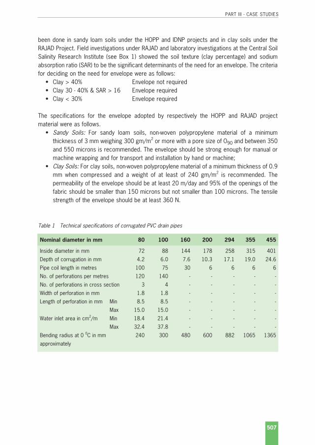
PART III - CASE STUDIES
507
been done in sandy loam soils under the HOPP and IDNP projects and in clay soils under theRAJAD Project. Field investigations under RAJAD and laboratory investigations at the Central Soil Salinity Research Institute (see Box 1) showed the soil texture (clay percentage) and sodiumabsorption ratio (SAR) to be the significant determinants of the need for an envelope. The criteriafor deciding on the need for envelope were as follows:
• Clay > 40% Envelope not required• Clay 30 - 40% & SAR > 16 Envelope required• Clay < 30% Envelope required
The specifications for the envelope adopted by respectively the HOPP and RAJAD projectmaterial were as follows.
• Sandy Soils: For sandy loam soils, non-woven polypropylene material of a minimumthickness of 3 mm weighing 300 gm/m2 or more with a pore size of O90 and between 350and 550 microns is recommended. The envelope should be strong enough for manual ormachine wrapping and for transport and installation by hand or machine;
• Clay Soils: For clay soils, non-woven polypropylene material of a minimum thickness of 0.9mm when compressed and a weight of at least of 240 gm/m2 is recommended. Thepermeability of the envelope should be at least 20 m/day and 95% of the openings of thefabric should be smaller than 150 microns but not smaller than 100 microns. The tensilestrength of the envelope should be at least 360 N.
Table 1 Technical specifications of corrugated PVC drain pipes
Nominal diameter in mm 80 100 160 200 294 355 455
Inside diameter in mm 72 88 144 178 258 315 401
Depth of corrugation in mm 4.2 6.0 7.6 10.3 17.1 19.0 24.6
Pipe coil length in metres 100 75 30 6 6 6 6
No. of perforations per metres 120 140 - - - - -
No. of perforations in cross section 3 4 - - - - -
Width of perforation in mm 1.8 1.8 - - - - -
Length of perforation in mm Min 8.5 8.5 - - - - -
Max 15.0 15.0 - - - - -
Water inlet area in cm2/m Min 18.4 21.4 - - - - -
Max 32.4 37.8 - - - - -
Bending radius at 0 0C in mm 240 300 480 600 882 1065 1365
approximately
India 26-7-2004.qxp 9-2-2005 14:29 Pagina 507

PART III - CASE STUDIES
508
Figure 3 Installation of a sand envelope in the ACRIP Appikalta Pilot Area, Andhra Pradesh: a) sealing thejoint; b) sand filter around a concrete drain and c & d) around a plastic drain
a b
c d
India 26-7-2004.qxp 9-2-2005 14:29 Pagina 508

PART III - CASE STUDIES
509
5 Installation equipment
Large-scale subsurface drainage installation is relatively new in India. International contractorsimported the drainage machinery and undertook the bulk of the installation under RAJAD project.For HOPP, the Netherlands Government provided a trencher, with which about 1000 ha area hasbeen covered so far.
6 Examples of large-scale drainage projects
6.1 Rajasthan Agricultural Drainage Research Project
The Rajasthan Agricultural Drainage Research Project (RAJAD) was the first major project toinstall subsurface drainage systems at a large-scale in India. The project was a joint undertakingfunded by the Government of Canada, Government of India and the State Government of Rajas-than. The project was a large-scale, applied research project on the use of horizontal subsurfacedrainage and associated water management techniques to control soil salinity and waterloggingproblems in irrigated agricultural lands. The project was located in the Chambal Command areain Rajasthan. The total Chambal Command area is 385 000 ha, of which 229 000 ha is underirrigation. Waterlogging and salinity problems followed the introduction of irrigation in the area inthe 1960's. The project aimed at:
• Capacity building of the state government and farmers to address the problems of water-logging and soil salinity;
• Development of design criteria for subsurface drainage through pilot area research;• Establishment of facilities for drain pipe supply;• Demonstration and implementation of large-scale mechanised subsurface drainage instal-
lation;• Construction of subsurface drainage using local machines and persons;• Pilot testing of Integrated Water and Agriculture Management.
The project started in 1991 and by the end of 1998 an area of about 15 000 ha was providedwith subsurface drainage at an overall costs of ¤ 41.3 million (2000 prices). The overall cropyield increased about 25%.
Project organizationThe Government of Canada designated the Canadian International Development Agency (CIDA)as the agency responsible for the implementation of the project and CIDA appointed a CanadianProject Executing Agency. The Commissioner of the Chambal Command Area Authority appoin-ted the Project Manager (Figure 4). A Project Steering Committee (PSC) was responsible for theprogramme review, policy, budget approval, external institutions coordination and report review.A Technical Coordination Committee (TCC) coordinated the Pilot Research and design criteriarecommendations.
India 26-7-2004.qxp 9-2-2005 14:29 Pagina 509

PART III - CASE STUDIES
510
PlanningRAJAD was an integrated project in which both research through pilot studies and implemen-tation of subsurface drainage in large areas took place. The following schedule was followed:
Delineation of saline areas was done by EM38-survey on a 77 ha grid. In the affected areas, soilsamples were collected on an 8.5 ha grid and analysed on mechanical and chemical properties.For classification of salt affected soils the following criteria were used:
RAJAD
Canadian Executing Agency
Canadian Team Leader
Commisioner, Chambal Command
Project Manager
Consultants, Canadian & Local
Canadian Drainage Contractor
Equipment suppliers
Training institutions
Land development & drainage construction
Nanta Research Lab
Irrigation
Water Users (Farmers) Associations
Drainage construction divisionsPilot plot monitoring
Item SSD(ha) '91 '92 '93 '94 '95 '96 '97 '98 '99 '00
Human resource development
Small test sites 410
Investigations & design
Large test sites 1010
Monitoring & evaluation
Pre-contract 1 700
Contract 1 10,671
Areas with patchy salinity 2134
Operation and maintenance
Figure 4 Project organisation of RAJAD
India 26-7-2004.qxp 9-2-2005 14:29 Pagina 510

PART III - CASE STUDIES
511
Class ECe (dS/m) ESP PH
Saline soil >4 <15 <8.5
Saline-alkali soil >4 >15 >8.5
Alkali soil <4 >15 >8.5
LayoutA composite subsurface drainage system was installed with field drains at an average depth of1.2 m and 60 m spacing connected to collector drains that discharge by gravity in open maindrains.
Drainage materialsCorrugated PVC drain pipes of seven sizes were used. The pipes were locally produced by aprivate company and were subject to stringent quality testing prior to use.
EnvelopesSynthetic fabric envelope materials were used in case the criteria for use of envelope mentionedin Chapter 4 required to do so.
Installation equipmentFour trenchless machines and one trencher were used. Initially only field drains were installed bythe trenchless ploughs and collectors were installed using excavators. The first machine to beused was a trenchless plough equipped with a 400 HP diesel engine and an operating weight of40 Mt. Its overall length when operating was 10.5 m with a width of 3.30 m and a height of 7.0m (3.0 m laser light receiver mast in the upright position). The second machine was a bulldozerwith a drainage plough added on the rear. In the international contract, in which subsurfacedrainage system has been installed in about 10,600 ha, two trenchless machines (one verticalplough and a V- plough) and a trencher were used. The V-plough was used to install drains ofØ 80 and 100 mm. The vertical plough was used to install the field and collector drains ofØ 160, 200 and 294 mm. Local equipment included: backhoe for excavating at joints,junctions, outlets and the like; bulldozers for removal of abrupt grade changes and restorationwork; tractors, trucks etc. for transportation of material and hydraulic vibrators for compaction.
Construction practicesPrior to installation, a laser transmitter was set up, calibrated to the nearest benchmarks andchecked to ascertain that the existing topography and proposed depth of the field and collectordrains was indeed correct. First the collector drain was installed. An excavator/backhoe thenexcavated down to the collector and a T-joint was connected to the collector pipe. The field drainpipe was fed through the plough boot, the connection elevation confirmed, connected to the T-joint, plough boot elevation set to design grade and finally installed by the plough. Aftercompleting the drain line, the machine returned over the same line to compact the soil and thenmoved on to the next line. A bulldozer followed the machine to compact the soil once more.Finally, the farmers levelled their fields in preparation for the subsequent crop season. A small
India 26-7-2004.qxp 9-2-2005 14:29 Pagina 511

crew restored the bunds, drains and watercourses disturbed by the machinery. As-builtconstruction drawings were prepared for operation and maintenance requirements. Under ex-treme wet conditions and during the monsoon season the work was suspended. Sometimes,however, it was required to pull the trencher by a bulldozer when and where local wet conditionsprevailed. The trenchless installation under wet conditions caused smearing and clogging of thesynthetic envelopes resulting in less than optimal performance of the drainage systems. In suchcases, additional field drains had to be installed to alleviate wet conditions in the fields. The rateof installation varies from 500 m/day for the combined mechanical/manual installation to morethan 5000 m/day for installation by trenchless drainage machine (Table 2).
Table 2 Installation rates of the different installation techniques achieved at RAJAD
Method Installation rate (m/day)
Manual installation with one backhoe and 20 labourers 500
Installation by excavator 1500
Installation by trenchless drainage machine 5000 - 6000
Experiences gained during installation resulted in the following list of precautions:• Construction management staff should be given comprehensive training in effective inspec-
tion and reporting techniques prior to the start of the installation;• A Construction Management Organisation with the clear division of responsibilities is es-
sential;• Laboratory testing and field inspection of PVC pipe and fittings must be a continuous, well
documented process of quality control to avoid installation problems and failures of thesystem;
• All faulty material should be rejected;• Laser set-up should always be double checked against control points and ground eleva-
tions prior to starting the actual installation of the drain pipes;• Grade control on collector and field drains is fundamental to the success of installation;• Installation work should start from the outlet drain and installation should then proceed up-
stream to prevent drainage water collecting in trenches;• Restoration work should start within 24 hours of the pipe installation.
6.2 Haryana Operational Pilot Project
Project objectivesThe Haryana Operational Pilot Project (HOPP) for the reclamation of waterlogged and saline landsof Haryana came into being in 1994 with the assistance of the Government of the Netherlands.The long-term objective of the project was to "build and strengthen the capacity of the Depart-ment of Agriculture (DOA) of Haryana to implement the subsurface drainage technology in the
PART III - CASE STUDIES
512
India 26-7-2004.qxp 9-2-2005 14:29 Pagina 512

PART III - CASE STUDIES
513
state and to create/act as a resource/knowledge base for the future interventions of subsurfacedrainage technology in waterlogged and salt affected areas of Haryana (and later in north-westIndia) including playing an active facilitating role in the development of a drainage policy in thestate and possibly in neighbouring states". The specific (short-term) objectives were:
• Transfer of technology (equipment, knowledge and skills) relating to the reclamation ofwaterlogged and saline lands in Haryana;
• Construction and operation of two horizontal subsurface drainage schemes, each of about1000 ha;
• Creation in Haryana of a nucleus organisation capable of:- Implementing subsurface drainage systems on about 2500 ha per year and maintaining
the resulting drainage network;- Attracting sufficient funds for the purchase of additional equipment, the actual con-
struction of drainage systems and for hiring the necessary staff.• The participation of farmers in the planning, construction, operation and maintenance of
the subsurface drainage systems;• The environmentally sound disposal of the saline drainage effluent of the pilot areas.
Project organisationThe organisations responsible for managing and implementing the HOPP were the Departmentof Agriculture, Government of Haryana, India and the Directorate General of International Co-operation, The Netherlands. The overall supervision and guidance was in the hands of two com-mittees whose members belonged to a number of organisations involved in drainage in Haryana(Department of Agriculture, Department of Irrigation, CSSRI, Haryana Agricultural University, andothers), as follows:
• Steering Committee headed by the Secretary of Agriculture of DOA in Chandigarh, forguidance on policy matters meeting at least twice a year;
• Technical Committee headed by the Director of CSSRI in Karnal to guide the Haryana OPPon the technical details meeting at least four times a year.
Consultancy was provided by the Netherlands through an Indo-Dutch consortium of consultingcompanies. To implement HOPP an organisational unit under the DOA was established withdeputations from other departments within Haryana (Figure 5). Based on a process approach, aKnowledge Management Unit (KMU) was established at Chandigarh together with a TechnicalAssistance Team to ensure the sustainability of the institutional memory from project ex-periences. In addition to assuming Monitoring and Evaluation (M&E) responsibilities, the KMUguided the implementing department (Subsurface Drainage Cell) to develop capacity buildingpackages, co-ordinate training on data collection, work processing and planning, gender sen-sitisation and farmers participation for field teams, farmers and contractors. The KMU was alsoresponsible for cultivating links with other agencies (e.g. Department of Irrigation) and assists inthe development of drainage policy initiatives in Haryana and elsewhere as appropriate. Theproject activities were grouped under the following work components:
• Project management;• Planning and design;• Construction of subsurface drainage and other field activities;
India 26-7-2004.qxp 9-2-2005 14:29 Pagina 513

PART III - CASE STUDIES
514
• Machinery maintenance;• Farmers participation and O&M;• Monitoring and evaluation.
The work programme was designed to ensure that full integration of all the components tookplace and that human resource development and training was linked to all components.
PlanningBefore HOPP started, CSSRI and Haryana Agriculture University conducted operational researchon waterlogging and soil salinity in sandy soils of Haryana. The recommendations of these stu-dies provided the required inputs for undertaking subsurface drainage construction under HOPP.The sequence of activities was as follows:
• Participatory Rural Appraisal (PRA) in the pilot areas, mapping the social landscape;• Rough layouts for the blocks based on maximum size of the drainage blocks, boundaries
of villages, minors, dirt roads, open drains and so forth;
OPP Supervison Steering/Technical Committee
Chief TechnicalAdvisor
Project Director(Dir. of Agr., DoA)
Deputy Project Director(Joint Dir. of Agr. (S.C.))
TA team Support section
Executive engineer
Planning
and design
section
Construction
section
Machinery
section
Farmer 's
participation
section
Land
development
and M&E
section
O&M
section
Extensionservices
DoA
CSSRI/HAUSci. supporting/training
M&E guidance
Engineering wing Non-Engineering wing
OP Project Team
Exec. Project Director(Add. Dir. of Agr. (S.C.))
Figure 5 Organogram of the Haryana Operational Pilot Project
India 26-7-2004.qxp 9-2-2005 14:29 Pagina 514

PART III - CASE STUDIES
515
• Motivational activities including the development of communication materials, orientationvisits to nearby mini pilot schemes and farmer field days;
• Detailed designs;• Verification of the designs in consultation with the farmers, changes in the designs were
made when feasible;• Obtain farmers' consent for the construction of the subsurface drainage system;• Formation of Farmers Drainage Societies including elections for the executive committee
and official registration according to the Societies Registration Act (1860) and bye-laws.The executive committee included one ex-officio member of HOPP;
• Construction of the subsurface drainage system with conflict resolution by the FarmersParticipation Section (FPS) staff;
• Handing over of (electric) pumps operation to the registered Farmer Drainage Societies.
The first subsurface drainage systems were installed in April 1997 in the Gohana area: in threeseasons about 1000 ha divided into 23 blocks with one pumping unit in each block were pro-vided with subsurface drainage. The drains were installed mechanically using imported trenchermachines. All blocks were handed over to the farmers' drainage societies in phases for operationand maintenance.
Then, the construction activities were shifted from government constructing units to a privatecontractor. Identification of areas requiring drainage, their prioritisation, undertaking investiga-tions, design and planning were carried out by the government and its own staff, while the con-struction was carried out by contractors and the systems operated and maintained by thefarmers' drainage societies.
LayoutComposite subsurface drainage systems were installed with corrugated PVC pipes for both thefield (Ø 80 & 100 mm) and collector (Ø 200 & 294 mm) drains. The field drains connect on bothsides to a collector pipe that discharge into a sump. Each sump serves around 50 ha, an areaof approximately 40 - 50 farmers being the maximum size of group that can organise themsel-ves. From the sump, the drainage water is lifted by pumping and disposed of into a surfacedrainage system. To prevent the inflow of fine soil particles into the pipes, nylon socks (for thecollectors) and polypropylene non-woven fibres (thickness >2 mm and an apparent opening sizeO90 > 300 microns) are used for the collector and field drains, respectively. Both pipe andenvelope materials were produced locally (Figure 6). The field drains are about 315 m in lengthand have an average depth of 1.7 m. The maximum depth of the collectors at the sump is 3 m.The design discharge is 2 mm/day, which has been reduced to 1.5 mm/day for the new pro-jects, resulting in a drain spacing of 60 to 67 m.
EquipmentThe Netherlands Government provided a trencher, with which about 1000 ha area has beencovered so far (Figure 7).
India 26-7-2004.qxp 9-2-2005 14:29 Pagina 515

PART III - CASE STUDIES
516
Figure 7 Trencher installing pre-wrapped corrugated drain pipe in Gohana area
CostsBased on the actual expenditure for the first 983 ha in Gohana (1997-1999) the total cost ofinstalling subsurface drainage amounted to ¤ 770 per hectare at 2000 prices (Table 3).
Figure 6 Wrapping the non-woven polypropyleneenvelope around the drain pipe
India 26-7-2004.qxp 9-2-2005 14:29 Pagina 516

PART III - CASE STUDIES
517
Table 3 Actual cost of installing subsurface drainage systems in Haryana, India
Item Cost per ha
(¤) (%)
Materials • Pipes 238 (31%)
• Envelopes 132 (17%)
• Structures a 59 (8 %)
Machinery • Fixed b 174 (23%)
• Variable c 131 (17%)
Miscellaneous 37 (5%)
Total 770 (100%)
a Structures include sump, pump house, pumps, electrification, manholes, labour, disposal (surface) drainage;b Fixed machine costs include interest (15%) and depreciation based on a lifetime of 7 - 10 years. A working time of 70
machine hours have been used for one block with an average working time of the construction plant (trencher, excavator,bulldozer, tractors and trailers) of 800 hrs per year;
c Variable costs include spare parts (estimated over lifetime), repairs (partly estimated), diesel and oil (actual).
6.3 Indo-Dutch Network Project
This third project is not an example of large-scale implementation but of applied research andsmall-scale implementation. To support the research activities in subsurface drainage design andsmall-scale implementation, the Indo-Dutch Project for waterlogging and soil salinity was inoperation for about 17 years (1985 - 2002). Between 1996 and 2002 this project was convertedinto a Network Operational Research Programme on Drainage and Water Management forSalinity Control in Canal Commands (IDNP). The overall objectives of the project were (i) tostrengthen research capacity of CSSRI and the four State Centres, especially in the field ofwaterlogging and salinity control, and (ii) to enhance awareness on drainage and related watermanagement for the control of waterlogging and soil salinity at State and Central level. Theobjective of the drainage pilot area research component was to conduct operational research ondrainage methods for reclamation of waterlogged and salt affected agricultural land in differentagro-climate zones of India. Eight pilot areas, ranging in size from 20-188 ha, were implementedin 5 agro-climate zones. Monitoring included one large-scale monitoring area of 2000 ha out ofwhich nearly 1200 ha were provided with subsurface drainage.
Project OrganisationThe IDNP project was implemented jointly by the Government of India through the Indian Councilof Agricultural Research (ICAR) and the Government of the Netherlands through the RoyalNetherlands Embassy (RNE) in India. The Implementing agencies in India were:Central Soil Salinity Research Institute (CSSRI), Karnal, Haryana (Box 1);
• Acharya N G Ranga Agricultural University (ANGRAU), Indo-Dutch Network Project, Bapatla,Andhra Pradesh;
• Gujarat Agricultural University (GAU), Soil and Water Management Research Institute,Navsari, Gujarat;
India 26-7-2004.qxp 9-2-2005 14:29 Pagina 517

PART III - CASE STUDIES
518
• University of Agricultural Sciences Dharwad(UASD), Agricultural Research Station, Bhee-marayanagudi, Karnataka;
• Rajasthan Agricultural University (RAU), Agricultural Research Sub-Station, Hanumangarh,Rajasthan.
Box 1 Central Soil Salinity Research Institute
The Central Soil Salinity Research Institute (CSSRI), established in 1969 under ICAR, is a central research institutelocated at Karnal, Haryana. It is a leading research centre in India in the fields of salt affected soils and waterlogging.Besides the main centre at Karnal, the institute has regional stations at Canning Town in West Bengal for coastal soils,at Anand in Gujarat for black soils and at Lucknow in Uttar Pradesh for alkaline soils of the Gangetic plains. It is also theheadquarters of the All India Coordinated Research Project on Management of Salt Affected Soils and Use of SalineWater for Agriculture, which has seven network centres located in different agro-climatic regions of the country. Themulti-disciplinary research at CSSRI is organised under the four following divisions:
• Drainage and Water Management Engineering;• Soils and Crop Management;• Crop Improvement, and;• Technology Evaluation and Extension.
The research on drainage concentrates on development of design criteria, testing of drainage materials, recycling ofdrainage water and socio-economic aspects through field research and modelling.
CSSRI was the coordinating agency and focal point for all the other network centres and theInternational Institute for Land Reclamation and Improvement (Alterra-ILRI), Wageningen, TheNetherlands, provided technical assistance to the project. The four state agricultural universities,often in cooperation with state departments or CADAs, had already started operational research.
OutputThe project provided the guidance for identifying problems, developing research programme,undertaking pilot research in farmers' fields, and analysis of results to develop solutions to water-logging and soil salinity. Multidisciplinary scientific teams under a chief scientist at each centreconducted the studies. The outputs were synthesised into recommendations for field depart-ments for implementation. The research activities resulted in major developments on the fol-lowing issues (for more details see Bibliography):
• Two methodologies, one based on visual and one for digital interpretation, were recom-mended for the identification of waterlogging and soil salinity conditions using remotesensing: These were based on eight studies covering areas ranging between 5 000 and350 000 ha in the Indo-Gangetic plains (3), heavy clay or black soils (3) and sandy soils(2);
• Recommendations on Waterlogging and Salinity Control were based on the researchfindings of 7 drainage pilot areas (of between 20 and 188 ha, Table 4), covering 5 agro-ecological sub-regions in India with soils ranging from sandy loam to heavy clay. Sugges-tions for open and pipe drains were presented for each sub-region specifications forsubsurface drainage systems;
• Computer modelling for irrigation and drainage: four computer simulation models, SWAP,UNSATCHEM, SALTMOD and SURDEV, were tested to assess the short and long-term
India 26-7-2004.qxp 9-2-2005 14:29 Pagina 518
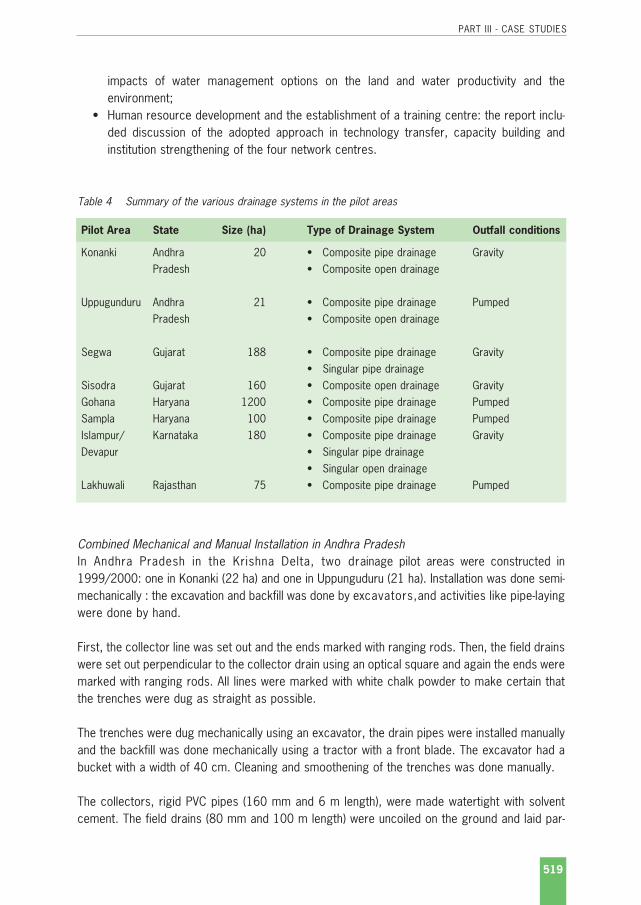
PART III - CASE STUDIES
519
impacts of water management options on the land and water productivity and theenvironment;
• Human resource development and the establishment of a training centre: the report inclu-ded discussion of the adopted approach in technology transfer, capacity building andinstitution strengthening of the four network centres.
Table 4 Summary of the various drainage systems in the pilot areas
Pilot Area State Size (ha) Type of Drainage System Outfall conditions
Konanki Andhra 20 • Composite pipe drainage GravityPradesh • Composite open drainage
Uppugunduru Andhra 21 • Composite pipe drainage PumpedPradesh • Composite open drainage
Segwa Gujarat 188 • Composite pipe drainage Gravity• Singular pipe drainage
Sisodra Gujarat 160 • Composite open drainage GravityGohana Haryana 1200 • Composite pipe drainage PumpedSampla Haryana 100 • Composite pipe drainage PumpedIslampur/ Karnataka 180 • Composite pipe drainage GravityDevapur • Singular pipe drainage
• Singular open drainageLakhuwali Rajasthan 75 • Composite pipe drainage Pumped
Combined Mechanical and Manual Installation in Andhra PradeshIn Andhra Pradesh in the Krishna Delta, two drainage pilot areas were constructed in1999/2000: one in Konanki (22 ha) and one in Uppunguduru (21 ha). Installation was done semi-mechanically : the excavation and backfill was done by excavators,and activities like pipe-layingwere done by hand.
First, the collector line was set out and the ends marked with ranging rods. Then, the field drainswere set out perpendicular to the collector drain using an optical square and again the ends weremarked with ranging rods. All lines were marked with white chalk powder to make certain thatthe trenches were dug as straight as possible.
The trenches were dug mechanically using an excavator, the drain pipes were installed manuallyand the backfill was done mechanically using a tractor with a front blade. The excavator had abucket with a width of 40 cm. Cleaning and smoothening of the trenches was done manually.
The collectors, rigid PVC pipes (160 mm and 6 m length), were made watertight with solventcement. The field drains (80 mm and 100 m length) were uncoiled on the ground and laid par-
India 26-7-2004.qxp 9-2-2005 14:29 Pagina 519

PART III - CASE STUDIES
520
allel to the trench and then the envelope (a geotextile and a nylon mesh) was wrapped aroundthe pipe in the field before the pipe was placed in the trench. Four labourers could wrap andplace about 250 m of pipe per day (Figure 8). Before the soil was backfilled it was crushed usingthe tractor blade.
Problems encountered during the installation and lessons learned were:• It was hard for one labourer to do the wrapping, therefore teams of four labourers were
engaged to do the job;• The binding wire used for wrapping the envelope material got easily twisted;• Delays in installing the pipes were often caused as a result of standing water in the trench-
es. Pumping was required to discharge this excess water;• Stability of the trench walls was poor and therefore the drain pipes needed to be installed
as soon as possible after excavation.
Combined Mechanical and Manual Installation in GujaratIn Gujarat in the Kakrapar irrigation command area, a 188 ha drainage pilot area was establishedin Segwa to test several layouts and configurations of subsurface drainage systems, namely,singular and composite systems and various drain depths and spacings. The following methodswere tried:
• Manual installation in a 9.1 ha block: drains were installed manually at a depth of 0.90 m.The tools used for the manual installation included: hoes, sticks, hand scrappers, rope,metal and wooden compactors, metal buckets and vessels and bailing buckets;
• Semi-mechanical installation in two blocks (18.9 ha): an excavator was used to dig thetrench up to 10-15 cm above the design level, all other activities such as levelling, grading,envelope wrapping, pipe-laying, backfill, were done manually (Figure 9).
Figure 8Wrapping of envelope material(nylon mesh) around the pipe inUppugunduru Pilot Area, AndhraPradesh
India 26-7-2004.qxp 9-2-2005 14:29 Pagina 520

PART III - CASE STUDIES
521
Figure 9 In Segwa, the drain trench was excavated mechanically and all other activities were donemanually: a) excavating the trench; b) checking the level; c) preparing the bed; d) checking thefinal level; e) checking the level at the outlet and f) laying the pipe
a b
c d
e f
India 26-7-2004.qxp 9-2-2005 14:29 Pagina 521

PART III - CASE STUDIES
522
Time studies were conducted to establish the labour requirements (Table 5). The overall labourrequirements in the manually installed block were 52 working days per 100 m drain (or 1.9m/day). For preparatory activities like setting out the alignment and levels, the labourrequirements were between 1 and 2 man-days per 100 m of drain, and for supporting activitieslike levelling, grading and smoothening the trench bottom, pipe-laying and backfill they werebetween 5 and 11 man-days. Thus the actual excavation of the drain trench took about 39 man-days per 100 m or 2.5 m/manday. The overall cost of installation of the completely manuallyinstalled system (approximately ¤ 495/ha at 2000 prices) was 27% higher than the cost of thesemi-mechanically installed system (approximately ¤ 385/ha).
Table 5 Labour requirements for the manual installation of pipe drains in Segwa Pilot Area
Labour requirements per 100 m of drain
[man-days]
Field drain Collector drain
Preparation:
Setting-out alignment 0.3 0.5
Pegging 0.1 0.2
Cleaning alignment 0.9 0.0
Marking 0.5 0.6
Subtotal - Preparation 1.8 1.3
Supporting activities:
Setting out levels 0.1 0.1
Placement of boning rods 0.1 0.0
Levelling and smoothing trench bottom 6.2 0.0
Pipe inspection 0.1 0.1
Laying of pipe 0.5 0.5
Backfill 2.6 2.4
Compaction 1.5 1.5
Subtotal - Supporting activities 11.1 4.6
Excavation of drain trench 39.2 Done by excavator
Grand total 52.1 5.9
Additional activities:
Wrapping envelope 1.3
Gypsum application a 5.3
Dewatering b 4.9
a In several trenches the backfill was mixed with gypsum to study the effect of gypsum application on sedimentation in thedrain pipes in these unstable soils (high SAR).
b In several trenches dewatering was required because of the inflow of excess irrigation water.
India 26-7-2004.qxp 9-2-2005 14:29 Pagina 522

PART III - CASE STUDIES
523
The major problems encountered with the manually installation of the pipe drains, the adoptedmethods to overcome these problems and the lessons learned were:
• In the block where the system was installed semi-mechanically, the installation of the pipescould not follow the digging of the trenches. This problem was caused by the rather highlabour requirements for supporting activities (5 - 11 labour days per 100 m of drain, seeTable 5) as well as insufficient labour availability;
• Extra time was needed to train the labours in the specific tasks, like wrapping, grading &smoothening the trench bottom, pipe laying and backfill. It was difficult to find enough skil-led labourers;
• A high labour input requires a higher input in supervision. The large number of labourersand the long distances in the field necessitated the use of walkie-talkies;
• The soils in Segwa Pilot area are rather heavy (clay content about 44%), when these soilsdry up manually excavation is hard and difficult. It was especially hard to get good quality(fine and crumbled soil particles) for the backfill on top of the pipe;
• On the other hand, these soils become sticky under wet conditions. Therefore, to avoidwaterlogged conditions, installation was not done in the monsoon season, but only in thesummer season (January - May) when rainfall is limited;
• Neighbouring farmers did not want to interrupt their irrigation practices, which on severaloccasions resulted in inflow of water in the trenches;
• In the deeper trenches or those parts of the area where the groundwater table was high,trench walls were unstable due to in-flowing groundwater. This resulted in sudden collapseof (part) of the trench, which not only caused extra work but also created a safety hazardfor the labourers working in the trench.
Manual Installation in KarnatakaIn Karnataka, 180 ha operational research pilot area was constructed in Islampur-Devapur alongthe Naraynapur Left Bank Canal. A singular open and pipe drainage system was installed in a14.9 ha block and a composite pipe drainage system in a 14.4 ha block. All installation activities,namely, excavation of the trench, laying of the pipes and backfill, were done by local labours.PVC corrugated pipes (Ø 80 and 100 mm) were installed at a spacing of 30 and 50 m, a depthvarying between 1.1-1.2 m (for the field drains) and 1.4-1.5 m (for the collector drains) andwrapped with nylon socks in part of the area. The installation technique was similar to the methodused in Segwa (see above), again with special emphasis on grade control. The only majordifference was that topsoil was used for the first layer of backfill (0.20 to 0.30 m on top of thepipe), as this was more stable than the excavated subsoil. This layer was compacted lightly usingwooden flats. Overall labour requirements for the installation of the composite system in the14.4 ha block was 127 days/ha at a cost of Rs. 5200 to Rs. 5500 per ha (1999-2000 prices).Labour requirements per 100 m of drain line corresponded to the Segwa Pilot area, namely,49.8 man-days per 100 m for Islampur-Devapur (Table 6) and 52.1 man-days per 100 m forSegwa (Table 5).
India 26-7-2004.qxp 9-2-2005 14:29 Pagina 523

PART III - CASE STUDIES
524
Table 6 Labour requirements for the manual installation of a composite pipe drainage system in 14.4 hain Islampur-Devapur Pilot Area
Activity Labour input Labour requirement
[man-days]
Men Women Total [man-days per 100 m of drain]
Land clearing:
- Collector line and outlets 50 50 6.4
- Field drain lines 75 75 2.6
Installation:
- Field drains (2890 m) 510 430 940 32.5
- Collector drains (782 m) 234 234 29.9
Construction of outlets and manholes:
- Mason 40 40 1.1
- Labour 60 50 110 3.0
Transport of pipes & materials 60 60 1.6
Watchman on site 90 90 2.5
Assistance to engineers 150 150 4.1
(setting out levels etc.)
Miscellaneous 30 50 80 2.2
Grand Total 1224 605 1829 49.8
On average a male labourer could install 6 to 8 m of field drain (excavation, installation andbackfill) per day and 4 to 5 m of collector drain. A couple (consisting of a female and malelabourer) could install 9 to 11 m of field drains per day. The labour requirements doubled onrainy days.
India 26-7-2004.qxp 9-2-2005 14:29 Pagina 524

PART III - CASE STUDIES
525
Case Study - The Netherlands
Netherlands 30-7-2004.qxp 9-2-2005 14:31 Pagina 525

PART III - CASE STUDIES
526
Netherlands 30-7-2004.qxp 9-2-2005 14:31 Pagina 526

PART III - CASE STUDIES
527
Case Study - The Netherlands
1 Background
1.1 Historical developments
In the Netherlands, 25% of the land is below sea level and about 65% of it would be flooded whereit not for the dykes (Figure 1). The climate is relatively mild with an average annual rainfall of about750 mm and an annual evaporation of about 475 mm. The removal of excess rainfall in com-bination with the low elevation, the lowest area is 6.5 m below mean sea level, requires anintensive drainage system to keep one's feet dry, both man and crops. The expansion of agri-culture in the Netherlands started some 1000 years ago with a gradual change from shiftingcultivation towards a more permanent development and occupation of the land. Farmers had tolearn to organise themselves to mobilise enough labour and capital under evolving authorities: ab-beys (1000-1200 AD), feudal rulers (1200-1500), locally organised groups (1300-1500) andwater boards (1300-present). Moreover the water management was influenced by private ormunicipal land reclamation companies and peat mining companies (1500-1700), companies todrain and reclaim lakes (1500-1900), and governmental services to reclaim lakes, swamps andheath lands (1900-2000). Field drainage has always been the responsibility of the land user andthe main drainage systems the responsibility of the above-mentioned institutions. Exceptions arethe large-scale, government-supported, land reclamation and land consolidation projects in thesecond half of the 20th century: in these projects both the field and main drainage systems wereimplemented.
1.2 Large-scale reclamations in the 20th century
The generally felt need for better agricultural production conditions in the 20th century resultedin a number of government-financed, long-term programmes in which the construction of subsur-face drainage systems was a significant part. Important programmes were the land reclamationprogramme in the former Zuiderzee area and the rural development programmes on the "oldlands", the so-called land consolidation projects. The public organisations involved in these pro-grammes were the IJsselmeerpolders Development Authority (for the newly reclaimed areas) andthe Government Service for Land and Water Use (for the "old lands" ). Both organisations weremulti-purpose organisations whose tasks included drainage installation. The IJsselmeerpoldersDevelopment Authority carried out most of the works themselves in forced account. The con-struction of drainage systems in the land consolidation projects was carried out by consultantsand contractors under contract with Government Service for Land and Water.
1.3 Commonly used subsurface drainage system
In the Netherlands, subsurface drainage systems are used in almost all agricultural lands, exceptin the peat areas, where a high groundwater table is require to reduce subsidence and only shal-
Netherlands 30-7-2004.qxp 9-2-2005 14:31 Pagina 527

PART III - CASE STUDIES
528
low open drainage systems are used. The most commonly installed subsurface drainage systemis a singular system with piped field drains discharging into open collector drains (Figure 2). Themain function of the field drains is to control the watertable level. The corrugated plastic fielddrains (Ø 60 mm) are installed at a depth of 1.0 to 1.3 m. In fine or reduced (risk of ochre for-mation) soil layers, voluminous organic (coconut fibres) envelopes were used in the past, butthey have been replaced by synthetic pre-wrapped envelopes. Depending on the drain depth andsoil texture, installation is done by either trencher or trenchless drainage machines (Part I Figure5.8). The discharge from the subsurface field drains and the surface runoff is removed by gravitythrough a system of open collector drains.
1.4 Present status of drainage in the Netherlands
As mentioned above, an intensive drainage programme was carried out in the Netherlands duringthe second part of the 20th century. In total some 750 000 ha in the "old lands" and 150 000 ha
Land periodicallyflooded by seaand or river waterswhen there wouldhave been no dikes
1 m + m.s.l.
0 80 km
Scheldt
Rhine
Meu
se
B e l g i u mG e r m a n y
N O R T H S E A
Figure 1 Land periodically flooded by sea and river
Netherlands 30-7-2004.qxp 9-2-2005 14:31 Pagina 528

PART III - CASE STUDIES
529
in the new polders were equipped with subsurface drainage systems. Generally speaking all agri-cultural lands that require drainage have been provided with subsurface drainage, except the peatlands. The peat lands that are mainly used for pasture can only be superficially drained to avoidoxidation and the subsequent subsidence. Therefore these areas are only equipped with a shallowopen drainage system that maintains water levels at around 0.5 m below the surface. Currently,most of the drainage installation in the Netherlands is replacement of defunct systems, improve-ments of drainage in case change of land use and drainage of urban and industrial sites.
2 Organisation of the water management
2.1 Water Boards
Water boards emerged in the 13th Century when land reclamation and protection against floodingbecame essential for survival. These water boards are an example of an effective and sustain-able self-managed organisation for the construction, management and maintenance of dykes anddrainage systems. Protection against floods and the agricultural development in many parts ofthe Netherlands was accomplished through cooperation among groups of landowners with acommon interest in drainage, thus engaged in community undertakings to remove excess waterfrom their holdings. These efforts eventually resulted in the creation of water boards. Within thewater board organisation, the farmers and landowners are responsible for the local water mana-gement engineering works such as the smaller dykes, watercourses and roads.
DrainSea or lake
Pumpingstation
Drain pipes
Secondary drainPrimary drain
Figure 2 The single subsurface drainage system in the Netherlands consists of pipe field drains, opencollector, secondary and primary drains and a pumping station
Netherlands 30-7-2004.qxp 9-2-2005 14:31 Pagina 529
PART III - CASE STUDIES
530
Overall responsibility for proper water management throughout the country rests with the nati-onal government that exercises authority over the provinces. The national government, in theperson of the Minister of Transport, Public Works and Water management, is responsible forwater management affairs of national concern. This Ministry has its own executive body for thisjob: the Directorate General for Public Works and Water management. The local and regional re-sponsibility for water management, as laid down in the constitution, rests with the water boards.The provincial governments supervise the work and the finances of the water boards: they setup and abolish water boards, determine the water management tasks to be undertaken by thewater board, the area in which it will work, the composition of the governing body and how itsmembers will be elected.
Traditionally, the tasks of the water boards in the Netherlands were:• Flood protection;• Conveyance and disposal of drainage water;• Maintaining of agreed minimum and maximum water levels in the drainage system.
These tasks have now been extended to include water quality management, ecological mana-gement, water conservation and flood prevention. Nowadays, the water boards may be chargedwith the following tasks:
• Water control: providing protection against flooding by means of dunes, dykes and quays;• Water quantity: managing the amount of water and ensuring that it is kept at the right level;• Water quality: combating water pollution and improving the quality of surface waters;• Management of the inland water ways and roads.
The role of the water boards as far as subsurface drainage is concerned is a normative and acontrolling one. If a farmer or a group of farmers wants to install a subsurface drainage systemthey need to obtain permission from the water boards. An application for the installation of asubsurface drainage system is judged on the basis of the following criteria:
• The effect on the neighbouring areas;• The discharge;• The quality of the drainage water.
Water boards always had to serve the interests (= functions of water) of different groups. In thepast, little conflict arose between agriculture and other sectors because the pressure on the landwas not yet dominant. If any conflicts presented between agriculture and peat mining, for in-stance, an extensive jurisprudence offered a verdict most of the time. Potential conflicts betweensub-sectors of agriculture over water management urged farmers to participate and de factothey became the only interest group represented in the water boards. During the 20th century,the parallel interdependency in drainage has grown considerably and water boards are now thearena of decision making on all functions of water, in which besides the farmers all concernedparties, like households, municipalities, industries, recreation and nature organisations have asay.
Netherlands 30-7-2004.qxp 9-2-2005 14:31 Pagina 530

PART III - CASE STUDIES
531
2.2 Government Service for Land and Water Use
The main task of the Government Service for Land and Water Use is the planning, preparationand supervision of the execution of land consolidation projects1. These projects embody multipleaims: besides improving the production conditions for agriculture, they include the preservationand development of nature, improvement of living conditions in rural areas, and development ofgreen belts around cities. Sectoral improvement of water management and a more rationalarrangement of agriculture land use is part of the programme. Central to the objectives to im-prove the water management is meeting water control requirements for agriculture and natureareas. Adjustments have to be made to the groundwater level as both land use and drainagerequirements change as years go by. Lowering the groundwater level is important in order toincrease productivity when growing agricultural crops. In addition, it increases the load-bearingcapacity of the soil to accommodate the heavier agricultural machines driven on the land, evenduring wet periods. Conversely, in certain areas where the soil is sensitive to drought, it may benecessary to maintain high groundwater levels in order to maximise crop growth, taking intoaccount (adjacent) nature areas that usually require a higher groundwater level than the sur-rounding agricultural land. In a rural development project, both agriculture and nature interestsare considered in the planning process. An appropriate water control system is designed for theproject area to achieve the desired groundwater levels by means of fixed or moveable weirs,thereby ensuring the best possible water levels in the drainage system (Figure 3). The fielddrainage is usually improved by constructing a new subsurface drainage system or modifyingthe existing one, but it also includes enlarging watercourses and renovating existing pumpingstations.
2.3 IJsselmeerpolders Development Authority
Initially, the IJsselmeerpolders Development Authority2 had no other task than to cultivate thenewly reclaimed land. Over the years, its task has evolved from land reclamation primarily foragriculture, to an integrated development of agriculture, urban settlement, forests, recreationalfacilities and nature reserves. This experience has given the IJsselmeerpolders DevelopmentAuthority worldwide recognition in the reclamation and development of new lands.
Reclamation ProcessThe first step in reclaiming land for the sea or lakes includes the construction of a ring dike, oneor more pumping stations and the dredging of the main drainage channels to the pumping
1 In the past decade nature development and realisation of the ecological main structure as part of spatial planning
and redevelopment of the rural areas has become an important part of the tasks of the Government Service for
Land and Water Use.2 The tasks of the IJsselmeerpolders Development Authority came to an end in 1997 with the completion of the
Southern Flevoland polder. The organisation merged into the Regional Directorate IJsselmeerpolders of the
Directorate General of Public Works and Water Management.
Netherlands 30-7-2004.qxp 9-2-2005 14:31 Pagina 531
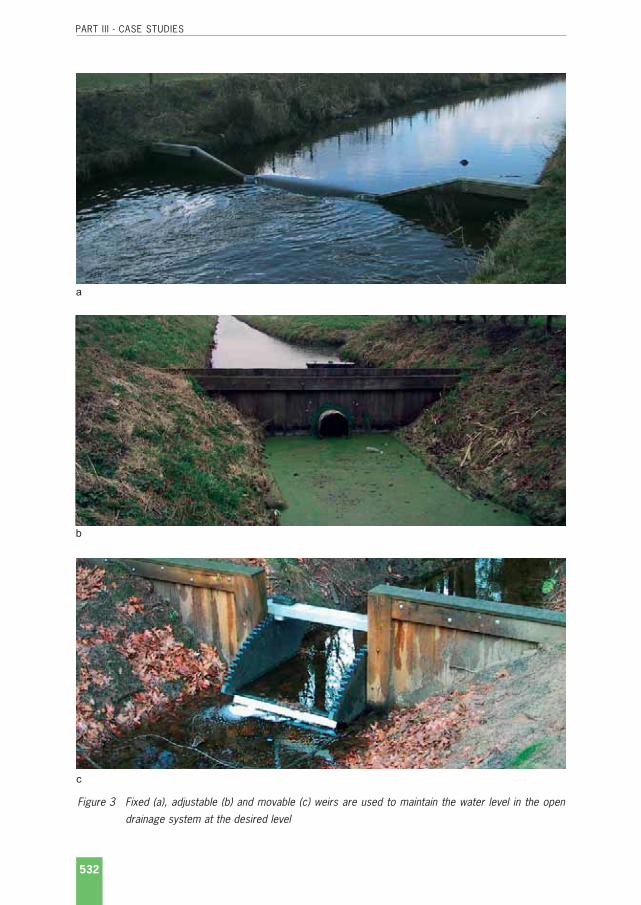
PART III - CASE STUDIES
532
Figure 3 Fixed (a), adjustable (b) and movable (c) weirs are used to maintain the water level in the opendrainage system at the desired level
a
b
c
Netherlands 30-7-2004.qxp 9-2-2005 14:31 Pagina 532

PART III - CASE STUDIES
533
stations. After these works are completed, the water is pumped out of the new polder. Once thepolder is drained, the land developers take over from the civil engineers. The tasks of the landdevelopers are to prepare the new land for agriculture (Land Use Department) and to pave theway for further development (Urban Development Department and the Socio-Economic Devel-opment Department). The Land Use Department is responsible for the rural development and forthe implementation of the works in the agricultural sector, including the land drainage systems,infrastructural works, rural roads and bridges, mechanised farming and afforestation. The nextstep is preparing the land for agriculture that starts with the aerial sowing of reed on the exposedmud flats. Reed speeds up the ripening process of soil with the result that the area becomesaccessible on foot and at a later stage by vehicle. The third and final step is the progressiveimplementation of the field drainage system, an essential measure to further ripen the soil andto progressively transform the reclaimed area into agricultural land. The first field drains areopen ditches usually spaced at intervals of 48 m. These ditches facilitate the drainage of surfacewater and the water in the surface layers. One year before cultivation starts, extra ditches aredug between existing ones at intervals of about 12 m. Finally, after a few years of cultivation,the ditches are replaced by subsurface drainage pipes (Figure 4).
Finally the drainage of the polders consists of the following elements:• Open ditches that after some years were replaced by piped subsurface drainage;• Open collector drains;• Secondary drains;• Primary drains;• Pumping stations.
2.4 The Drainage industry
The activities in both the large land consolidation projects and the reclamation of the IJsselmeerpolders prompted the development of modern mechanised drainage techniques. The need forefficient and reliable installation of pipe drains in large areas coupled with increasing labour costand labour scarcity facilitated and gave an economic basis to the development of moderndrainage trenchers and later trenchless drainage machines. The switch from the cumbersomeheavy tile drains to the corrugated plastic drain pipes was made in the same period thanks tothe development of the plastic industry and the large volumes of pipes required that made invest-ment in development and production of machinery attractive. The development of pre-wrappedenvelopes, first made of voluminous coconut fibres and later on of voluminous synthetic fibres,was prompted by the need for envelopes in most soils and the high price of gravel.
These developments were the result of a rather unique cooperation between the governmentservices, the research departments of universities and of these government services, the ma-chine building industry, the plastic industry, the land development companies and consultants.This cooperation resulted in:
• Modern drainage techniques that with adjustments are now applied world-wide;• A specialised industry for the production of drainage machines;
Netherlands 30-7-2004.qxp 9-2-2005 14:31 Pagina 533

PART III - CASE STUDIES
534
0.60 m
48 m
Reed
Ditch
1 Year
0.60 m
12 m
2 - 3 Years
Rape seedWinter wheatBarley
1.20 m
Rape seed
48 m
Subsurface drain
1.10 m
Several kinds of crops
Figure 4 Sequence of drainage measures during the reclamation of Southern Flevoland
Netherlands 30-7-2004.qxp 9-2-2005 14:31 Pagina 534

PART III - CASE STUDIES
535
• Specialised drainage contractors, and;• A specialised industry for the production of drain pipes and accessories as well as pre-
wrapped envelopes.
2.5 Drainage Contact Group
To enhance to cooperation between the various partners involved in agricultural land drainagethe so-called Drainage Contact Group was formed. This group organised study and extensionmeetings on a regular basis to ensure that all parties are kept up-to-date with the latest devel-opments in the sector and that their interests were taken into consideration. While the initiativeto organise these meetings came from (semi-) government organisations, farmers, manufac-tures and consultant organisations also played an important role. During the meetings they hadthe opportunity to express their views on recent developments, new rules and regulations anddiscuss the difficulties encountered by the implementation. The (semi-) governmentorganisations, on the other hand, could sound out the general feeling for proposed changes inthe existing rules and regulations and got feedback on new developments. The Drainage ContactGroup also played an important role in setting up applied research, and improving the quality ofwork and setting higher quality standards.
2.6 Research institutes
An important factor in the resources management system is the scientific knowledge complex,through which new and existing knowledge from research is disseminated via education,publications and extension services. This scientific knowledge complex (including drainage re-search) has changed considerably over the past decades as itemised below:
• The number of research institutes has been drastically reduced through successive roundsof merges: for instance, in Wageningen, the main centre for agricultural research in theNetherlands, the seven research institutes and the departments of Wageningen Agricul-tural University involved in agricultural water management have merged into one Know-ledge Centre under the umbrella of Wageningen University and Research Centre, of whichAlterra-ILRI is part of;
• The same applies to the institutions for secondary and higher vocational training, whichalso have gone through a round of mergers and concentration;
• Research programmes have evolved from single-disciplinary research on basic plant-soil-water relationships to interdisciplinary research involving all aspects of the effects of inter-ventions in the complex natural resources systems;
• The change from a government-sponsored and owned research complex in to a privatisedorganisation where research programmes have become demand driven instead;
• The integration of research and education and society as a whole. The introduction ofdemand-driven research has improved the representation of all stakeholders and reducedthe accumulation of power (as knowledge is power) with only a few privileged groups left.
Netherlands 30-7-2004.qxp 9-2-2005 14:31 Pagina 535

The mandate of Alterra-ILRI is to collect and disseminate knowledge for better and sustainableuse of land and water resources. This includes the following tasks:
• To collect information on land reclamation and improvement all over the world;• To disseminate this knowledge through publication, courses, and consultancies;• To contribute -by supplementary research- towards a better understanding of the land and
water problems in developing countries.
2.7 Farmers
As mentioned before, farmers always have been responsible for the installation of a subsurfacedrainage system on their land. A farmer who wants to install a system needs to obtain permis-sion from the Government, in particular the water board. The water board will check whether theproposed system is in line with the current regional rules and regulations that, for example,stipulate that the system should not exceed the maximum permissible lowering of the watertable, quantity and quality of drainage. Once permission has been obtained, the farmer will en-gage a drainage contractor. The drainage contractor guarantees that the drainage system isinstalled according to the Standard Rules and Regulations for the implementation of drainageworks.
3 Drainage materials
3.1 Pipes
The diameter of the PVC corrugated pipes used for subsurface drains ranges between 50 and200 mm. As the length of the field drains of the singular systems used in the Netherlands is mosttimes limited to about 200 mm, pipes of 60 and 80 mm diameter are mainly used. Dimensions,quality criteria and testing methods are standardised, under the authority of the "NederlandsNormalisatie Instituut" (Netherlands Normalisation Institute). There are several standards avail-able for drain pipes and envelopes (Table 1). Quality certification is done by an independentorganisation: "Stichting voor Onderzoek, Beoordeling en Keuring van Materialen en Construc-ties/KOMO" (Institute for Research, Judgement and Testing of Materials and Constructions).
Table 1 Netherlands standards for drain pipes and envelopes (in Dutch) a
Standard Subject
NEN 7036 Corrugated unplastised PVC pipes for sub-soil drainage
NEN 7047 Wrapping material made of coconut fibre for land drainage pipes
NEN 7048 Wrapping material made of peat-fibre for land drainage pipes
NEN 7090 Wrapping material made of polypropylene fibres for land drainage pipes
a Nederlands Normalisatie Instituut, P.O. Box 5059, 2600 GB Delft, The Netherlands
PART III - CASE STUDIES
536
Netherlands 30-7-2004.qxp 9-2-2005 14:31 Pagina 536

PART III - CASE STUDIES
537
3.2 Envelopes
Most of the soils in the Netherlands require an envelope. Apart from their hydraulic and filterfunction, envelopes are also useful in areas where the formation of iron ochre is likely to occur.The most widely used envelope materials were organic materials such as coconut and peatfibres, but they have been gradually replaced by voluminous envelopes made of polypropylenefibres. On a smaller scale, especially on sandy and loamy soils, thin synthetic envelopes are alsoused. Gravel envelopes are only used in exceptional cases, e.g. in urban and industrial sites andin areas where quick sand problems are encountered (Box 1), as gravel is scarce in the Nether-lands and hence the supply and transport is very expensive. Similar to drain pipes, the com-position, quality and testing methods are standardised (Table 1)
Box 1 Planning the supply of gravel for subsurface drains in the Lauwerszee project area
The planning of the gravel supply in a subsurface drainage area is illustrated by an example of the installation ofsubsurface drains in the Lauwerszee project area in the northern part of the Netherlands. Gravel was used because ofthe unique soil and hydrological conditions (quick sand) and the proposed land use (recreation and military trainingground). The gravel had to be transported by ship to the project area over a rather long distance, more than 250 km(Figure 5). The gravel was a by-product of the gravel used for housing and road construction and its availability is limited.The supply rate of gravel was less than the amount needed during the period of drain installation. Therefore, a ratherlarge amount of gravel had to be in kept in stock (Table 2 and Figure 6). The required amount of gravel was based onenvelope of 40 cm of gravel around a drain of 200 m length. The amount of gravel required was 26 m3, namely, 9 loadsof 3 m3 each drain. The calculation shows that at least 3600 m3 of gravel had to be in stock before the drain installationcould start and that the supply had to start at least 12 weeks before the drain installation begins.
Table 2 Calculation of amount of gravel needed in Sub-area no.5 Lauwerszee
Total drain length 60 kmAverage amount of gravel needed per km 100 m3
Total amount of gravel 6000 m3
Drain installation per week 7.5 kmAmount of gravel per week 750 m3
Supply of gravel per week 300 m3
Duration of drain installation 8 weeksDuration of gravel supply 20 weeks
From the temporary storage the gravel was transported to the drainage machine in so-called dump-carts and via a graveltrailer with a conveyor belt into the container on the trench box of the drainage machine. The speed of the gravel trailerneeded to be the same as the speed of the drainage machine, because stopping the drainage machine waiting for gravelsupply had to be avoided, as this had a negative effect on the drain alignment. The total number of equipment neededand the time needed for the supply of gravel from temporary storage to the drainage machine is presented in Figure 7.
Figures of box 1 on the next pages.
Netherlands 30-7-2004.qxp 9-2-2005 14:31 Pagina 537

PART III - CASE STUDIES
538
Figure 5 The Lauwerszee project area and the location of the gravel supply site
M2 - 14
M2 - 31
M2 - 15
M2 - 30
M2 - 16
M2 - 29
M2 - 17
M2 - 28
M2 - 27M
2 - 26
M3 - 25
M3 - 25
M2 - 32
45
4
1
4
3
2
M3 - 19
M3 - 20
M3 - 21
M3 - 22
M3 - 26
M3 - 18
M3 - 23
M3 - 17
M3 - 16
M3 - 15
M3 - 14
M3 - 34
M3 - 35
M3 - 13
M4 - 04
M4 - 11
M4 - 05
M4 - 06
M4 - 10
M4 - 07
M4 - 09
M4 - 08
M4 - 15
M4 - 12
M4 - 13
M4 - 25
M4 - 14
0 1 km
Recreational area
Collector drain
Open drain
Forest with tracks
Number of sub area5
Lauwerszee
Location gravel
Rifle range (restricted)
Brackishmarsh land(restricted)
W a d d e n S e a
Netherlands 30-7-2004.qxp 9-2-2005 14:31 Pagina 538

PART III - CASE STUDIES
539
Figure 6 Duration of gravel transport from the gravel pit to the project area
Figure 7 Schedule of activities of gravel supply equipment and duration
0
1000
2000
3000
4000
5000
-12
Transport
Gra
vel (
m3)
6000
-10 -8 -6 -4 -2 0 2 4 6 8
Weeks
Start drain installationInstallation
Minimum stock-pile
Dra
in (
km)
0
10
20
30
40
50
60
Dump trailer no. 2
1
Adjusting or provisioning
New drain
Drain installation
Driving back
Unloading gravel into the gravel hopperon the drainage machine or into gravel trailerTransport
Stand-by or driving along
Loading of gravel
Waiting at the temporary gravel storage
Dump trailer no. 1
Gravel trailer no. 3
Gravel trailer no. 2
Gravel trailer no. 1
Drainage machine
1 2 3 4 5 6 7 8 9 10 11 12 13 14 15 16 17 18 19 20 21 22 23 24 25 26 27 28 29 30 31 32 33 34
Time (minutes)
Equipment
0
Drainage machine Dump trailer / gravel trailer
Netherlands 30-7-2004.qxp 9-2-2005 14:31 Pagina 539

PART III - CASE STUDIES
540
4 Installation
4.1 Manual installation
Nowadays, manual installation of pipe drains is obsolete in the Netherlands, but in the first half ofthe 20th century, most drains were installed by hand. In that period a wealth of experience withmanual installation was built up and realistic and precise standards for a large variety of conditionswere developed. The amount of earthwork a labourer can handle varies considerably from place toplace, mainly depending on the type of soil (Table 3). On average, digging a trench requires a labourinput of about one labourer-day per metre per hour. A word of caution: in other countries, especiallyin the tropics, conditions are often much more difficult, so these figures serve only as a guideline.
Figure 8 End chute to protect the side slope of the open collector drain against erosion
3.3 Structures
As was mentioned before, most subsurface drainage systems in the Netherlands are singular,thus only a limited number of structures are needed, mostly confined to special conditions, suchas:
• Drain bridges, and;• Manholes for flushing and control.
The other accessories for pipe drains are standardized:• Couplings to connect pipes with the same and different diameters;• T-joint and cross-joints;• End caps;• End chutes to avoid erosion of the banks of the collector drain (Figure 8).
Netherlands 30-7-2004.qxp 9-2-2005 14:31 Pagina 540

PART III - CASE STUDIES
541
Table 3 Guidelines for labour input earth movement using manual labour
Activity Labour input hours/m3
Sand Clay
Excavation, including loading the spoil in a wheelbarrow:
• Up to 0.75 m depth 0.4 0.5
• 1.0 - 1.5 m depth 0.5 0.8
4.2 Mechanical installation
Mechanized drain laying was introduced in the 1950s. Initially American wheel diggers wereexperimented with. These machines had a low production per hour and therefore soon chaindigging machine were developed. The performance and the capacities of trenchers has beenfurther improved and developed since then (Figure 9). A modern trencher with laser control caninstall 400 - 500 m of corrugated drain pipe (Ø 60 mm) per hour, at a depth of 1-1.4 m.
Figure 9 Development of drainage machines in The Netherlands
1950 - 1960
Trencher with digging wheel Trencher with digging chain Trencher with half tracks
Trator trencher installing clay pipes Trencher with "flat" digging chain Trencher installing rigid plastic pipes
Trencher with "steep" digging chain Vertical plough Trencher V-plough Trencher
1960 - 1980
1980 - 2000
Netherlands 30-7-2004.qxp 9-2-2005 14:31 Pagina 541

The use of trenchless drain techniques has expanded since the 1980s. Approximately 2/3 oflateral drains are installed by trenchless drainage machines. With trenchless installation 500 to750 m of drain can be installed per hour. Large part of the agricultural land in the Netherlandsis used as pasture. Trenchless drain installation is causing very little damage to the grass land.Moreover, installation costs are lower and the production is higher.
In newly reclaimed areas trenchers are preferred. Clay in the reclamation areas is highly satura-ted with water. Leaving the trench open for some time after digging will increase evaporationand the ripening process is accelerated. The trenchers are equipped with a knife at the trenchbox to scrape off a small portion of the ripened topsoil into the trench ("blinding" ) on top of thedrain pipe (Figure 10)
PART III - CASE STUDIES
542
Figure 10 Trencher operation in reclamation area with blinding knife at the trench box
Netherlands 30-7-2004.qxp 9-2-2005 14:31 Pagina 542
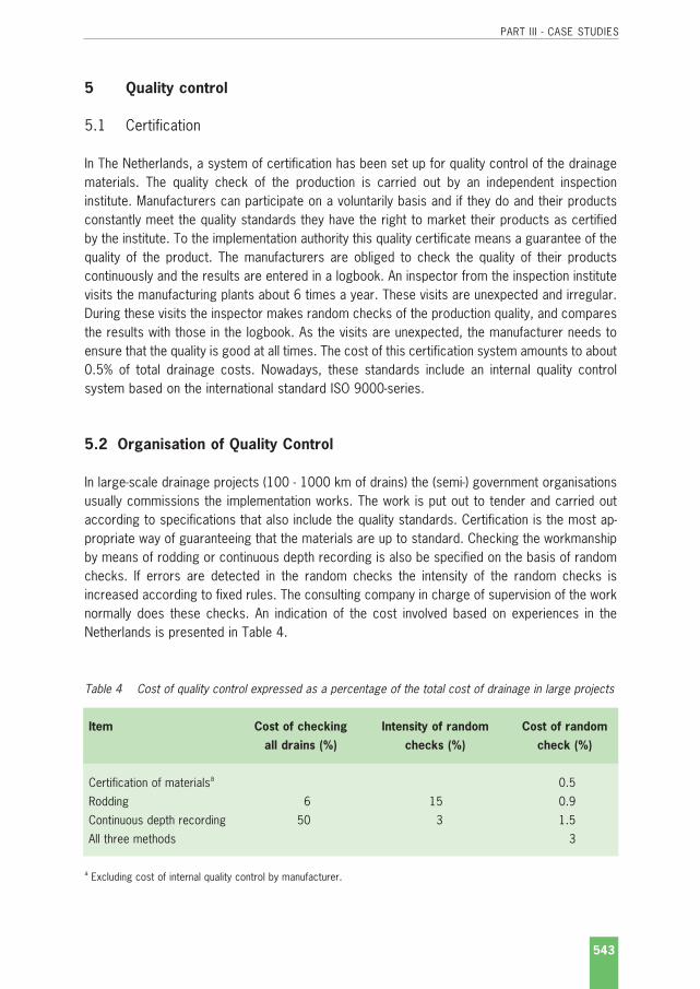
PART III - CASE STUDIES
543
5 Quality control
5.1 Certification
In The Netherlands, a system of certification has been set up for quality control of the drainagematerials. The quality check of the production is carried out by an independent inspectioninstitute. Manufacturers can participate on a voluntarily basis and if they do and their productsconstantly meet the quality standards they have the right to market their products as certifiedby the institute. To the implementation authority this quality certificate means a guarantee of thequality of the product. The manufacturers are obliged to check the quality of their productscontinuously and the results are entered in a logbook. An inspector from the inspection institutevisits the manufacturing plants about 6 times a year. These visits are unexpected and irregular.During these visits the inspector makes random checks of the production quality, and comparesthe results with those in the logbook. As the visits are unexpected, the manufacturer needs toensure that the quality is good at all times. The cost of this certification system amounts to about0.5% of total drainage costs. Nowadays, these standards include an internal quality controlsystem based on the international standard ISO 9000-series.
5.2 Organisation of Quality Control
In large-scale drainage projects (100 - 1000 km of drains) the (semi-) government organisationsusually commissions the implementation works. The work is put out to tender and carried outaccording to specifications that also include the quality standards. Certification is the most ap-propriate way of guaranteeing that the materials are up to standard. Checking the workmanshipby means of rodding or continuous depth recording is also be specified on the basis of randomchecks. If errors are detected in the random checks the intensity of the random checks isincreased according to fixed rules. The consulting company in charge of supervision of the worknormally does these checks. An indication of the cost involved based on experiences in theNetherlands is presented in Table 4.
Table 4 Cost of quality control expressed as a percentage of the total cost of drainage in large projects
Item Cost of checking Intensity of random Cost of random
all drains (%) checks (%) check (%)
Certification of materialsa 0.5
Rodding 6 15 0.9
Continuous depth recording 50 3 1.5
All three methods 3
a Excluding cost of internal quality control by manufacturer.
Netherlands 30-7-2004.qxp 9-2-2005 14:31 Pagina 543

PART III - CASE STUDIES
544
In small-scale projects commissioned by private farmers (2.5 and 10 km of drain), the tenderdocuments normally do not include rules and regulations concerning the quality of the work. Thismay result in poor quality work. To improve the quality the Government Service for Land andWater Use issued a model for a standard contract for private drainage works in 1984. Thisstandard contract contains the quality control methods discussed above. In another devel-opment, the farmers' and drainage contractors' organisations decided in 1987 - on the farmers'initiative - to establish a foundation to improve the quality of drainage work. The procedure ismore or less analogous to the procedure for certification of materials discussed above. Con-tractors have their work supervised by this foundation and if their work is up to standard theyreceive a certificate. The cost of this system comes to about 2% of drainage costs. The possi-bility to apply this system in the whole of the Netherlands is being studied.
Netherlands 30-7-2004.qxp 9-2-2005 14:31 Pagina 544

PART III - CASE STUDIES
545
Case Study - Pakistan
Pakistan 28-7-2004.qxp 9-2-2005 14:37 Pagina 545

PART III - CASE STUDIES
546
Pakistan 28-7-2004.qxp 9-2-2005 14:37 Pagina 546

PART III - CASE STUDIES
547
Case Study Pakistan
1 Background
Waterlogging and salinity is a serious threat to irrigated agriculture in Pakistan: of the 16.7 mil-lion ha in the Indus Basin about 2 million ha are waterlogged and 6 million ha salt affected. Themajor parts of the irrigated areas in Pakistan where drainage is needed have little slope.Therefore the disposal of the drainage effluent by gravity is in general not possible. The standardsubsurface drainage system is a composite system, with buried field and collector drains.Sumps are used to pump the drainage water from several collector drains in open main drains.Figure 1 shows the location of the major pipe drainage projects in Pakistan.
Figure 1 Pipe drainage projects in Pakistan
Pipe drainage projectsProvincial boundaryInternational boundary
ISLAMABAD
Mardan Swabi
Sutley RiverRavi River
ChanbRive
r
Jhe
lum
Riv
er
Indus
Riv
er
PehurPeshawar
Kushab
FourthDrainage
Lahore
Quetta
Karachi
D.G. Khan
D.I. KhanCCADP
Punjab
Baluchistan
Fordwah EasternSadiqia (South)
EastKhair pur
Sindh
Northwest FrontierProvince
Mirpurkhas INDIA
AFGHANISTAN
ARABIAN SEA
CHINA
0 200 km
Pakistan 28-7-2004.qxp 9-2-2005 14:37 Pagina 547

PART III - CASE STUDIES
548
2 Organisation
2.1 Historical developments
Drainage in Pakistan is generally executed within the canal irrigation commands. In 1958, theWater and Power Development Authority (WAPDA) was established as the agency responsible forthe coordination of design, construction and initial operation of the engineering works. Afterdecades of irrigation development, the enormous protective irrigation systems of Pakistanbegan to experience problems with rising groundwater tables caused by inefficient water deliverysystems and inequitable water distribution. In the 1960's WAPDA launched some 51 SalinityControl and Land Reclamation projects (SCARP's) to provide vertical drainage to combat theseproblems. The SCARP projects were initiated with loans from the World Bank. WAPDA wasresponsible for the design, construction and initial operation and monitoring of these deeptubewell projects, after which the Provincial Irrigation Departments (PID's) took over operationand maintenance.
As the drainage fees cover only around 20% of the actual expenses of O&M, the financial burdento operate and maintain the public tubewell systems became gradually too much for the PID's.These problems were aggravated because the life expectancy of most SCARP's proved to beless than half the expected life time. To overcome these problems, the irrigation and drainagesector was reformed and in 1997 Provincial Irrigation and Drainage Authorities (PIDA's) wereestablished in all four provinces. System management is to be decentralised and farmers are totake part in the system development and to take over O & M. This is realised by the creation ofArea Water Boards (AWB's) and Farmer Organisations (FO's). PIDA's facilitate and promote theformation of AWB's, which compose of farmers, government and PIDA representatives. AWB'son its turn facilitate and promote the formation of FO's. The PIDA's are responsible for theplanning, construction, operation and maintenance of the system at main and secondary level.At tertiary level, the FO's are responsible for O & M of the system. All these organisations haveto become financial autonomous by levying water charges and drainage fees. The establishmentof FO's and AWB's is however hampered by (i) a lack of farmers' involvement in policy reforms;(ii) the weak legal framework (the PIDA Acts) to implement reforms; (iii) lack of knowledge withinthe FO's and AWB's to develop and implement strategies to deal with the systems' problems and(iv) to make the shift from engineering to institutional solutions.
2.2 International Waterlogging and Salinity Research Institute
To counteract the waterlogging and salinity problems, the Ministry of Water and Power, underthe umbrella of WAPDA, and with the assistance of the UN, established the InternationalWaterlogging and Salinity Research Institute/IWASRI, in Lahore, Punjab in 1985. The overallobjectives of IWASRI are to co-ordinate and to conduct research on waterlogging and salinity inPakistan. Over the years IWASRI's mandate has evolved but its intentions and functions havelargely remained the same. End-users of IWASRI's research include farmers, planners anddesigners, policy makers, national research institutes and the drainage industry.
Pakistan 28-7-2004.qxp 9-2-2005 14:37 Pagina 548

PART III - CASE STUDIES
549
To assist IWASRI, The Governments of Pakistan and The Netherlands in 1988 initiated theNetherlands Research Assistance Project/NRAP, a collaboration between IWASRI and Altera-ILRI.The main aim of NRAP, which covered the period 1988-2000, was to conduct a multidisciplinaryresearch programme on waterlogging and salinity with special attention to drainage engineering,groundwater hydrology and land reclamation. In the second phase of the project, the devel-opment of a participatory approach to drainage was included. The project yield valuable resultsin the following fields:
• Technical lessons learned, in particular: (i) design criteria for gravel and synthetic envelopematerials; (ii) drainage design with computer simulations; (iii) drainage design criteria; (iv)salinity measurements by magnetic induction; (v) interceptor drainage; (vi) groundwaterapproach to drainage design; (vii) operation and maintenance of drainage systems (viii)benefits of shallow drainage, and (ix) the use of poor quality water for crop production andreclamation;
• Participatory drainage development: lessons learned on development and implementationof Bahawalnagar Subsurface Drainage Pilot Area (112 ha) in the Fordwah Eastern SadiqiaIrrigation and Drainage Project;
• Institutional development, including capacity building at ISWARI, through training and theexecution and dissemination of research.
2.3 Implementation of subsurface drainage projects
Most subsurface drainage works are implemented on the project basis. For each project aconsortium is formed under the authority of WAPA. Such a consortium normally consists of aprivate (most times foreign) or public contractor and a consulting engineering firm (both localand foreign) to assist with the design and supervision. Salient features of some major projectsare discussed in Chapter 5.
3 Drainage materials
Field drainsIn Pakistan, corrugated perforated PVC pipes are used for subsurface field drains. As thehydraulic conductivity of the soil is relatively high (e.g. in Mardan Scarp in the Northwest FrontierProvince the hydraulic conductivity ranges between 1 and 3 m/d), the spacing between fielddrains is large and consequently the pipe diameters are rather big (> 100 mm, Table 1).
Pakistan 28-7-2004.qxp 9-2-2005 14:37 Pagina 549

PART III - CASE STUDIES
550
Table 1 Materials used in some major drainage projects in Pakistan
Project EKTDP a FDP b Mardan Khusab
Size of 280 - 450 ha 380 - 400 ha 100 - 300 ha
the unit
Field drains 100 mm corrugated 100 - 200 mm PVC 100 mm PVC pipe 100 & 150 mm
PVC pipe pipe PVC pipe
Envelope Gravel Natural river run Mainly gravel but for Gravel mainly but
gravel with Hydraulic some collectors for IWASRI research
Conductivity >15m/d synthetic fabric synthetic envelope
envelope was used was used on one
sump
Collector 225 - 450 mm CC Perforated Perforated 100, 100, 150, 200,
drains and 250 - 300 mm 250 - 375 mm 150, 188, 250 & 250, 300 &
PE pipes PVC pipes 300 mm PVC pipe 380 mm PVC pipe
Sumps Pumps provided 79 numbers circular Outflow was by Total 56 sumps.
3.05 m diameter gravity and therefore 45 circular and 11
masonry well on no Sump required rectangular
RCC base slab. One
to three pumps of
each 2.25 cfs capacity
a East Khairpur Tile Drainage Project, Sindh Provinceb Fourth Drainage Projects, Faisalabad, Punjab Province
Collector drainsIn the first major subsurface drainage project, EKTDP, concrete pipes were used as collectorsbut their installation under the prevailing high water table and unstable subsoil conditions provedto be extremely difficult and the work progressed slowly. The concrete collector drains did notalways perform well due to dislocation of the pipes. Therefore, perforated large diameter PEpipes with gravel envelope were installed in the remaining part of the EKTDP project. In all thefollowing projects, perforated plastic PVC pipes are being used. Nowadays, plastic T-joints areused to connect the field and collector drains (Figure 2).
EnvelopesMost soils in Pakistan are fine-textured (silty loam, sandy loam, silty clay etc.) and require anenvelope material. No well-established criteria to determine the need and type of envelopeexisted, mainly gravel envelopes were installed (Table 1) generally based on design criteriadeveloped in the USA (USBR, SCS and others). Serious problems occurred with the crushed rockenvelope at the FDP although it was designed according to the specifications (Chapter 5.4).River-run gravel envelopes (having rounded particles) of the same specifications performedbetter, stressing the need for local verification of these rather site-specific criteria.
Pakistan 28-7-2004.qxp 9-2-2005 14:37 Pagina 550

PART III - CASE STUDIES
551
Figure 2 Before the field drains are installed, the field drain is connected to the collector drain using aplastic T-joint
SumpsSumps are provided for the collection of effluent from the collectors. These sumps are generallya circular brick masonry structure, with a depth of 5 to 7 m (15 to 20 feet) below the soil sur-face. One to three pumps are installed in a sump for the evacuation of drainage effluent to thesurface drain. Electric sensors are provided for automatic operation of the pumps.
4 Installation
DewateringSubsurface pipe drains are generally installed when the groundwater table is high. Moreover, inlarge areas the soil conditions are such that the subsoil is unstable. Therefore, before the con-struction at a particular unit starts, the contractor will install dewatering equipment (vertical wellpointing) and diesel pumps to dewater the site of the sump. The sump is constructed beforelaying the collector and field drains. Dewatering of the sump starts immediately when the instal-lation of the collector starts. Diesel pumps are also operated to dewater the sites where con-nections between field drains and collector are made.
Installation of Gravel EnvelopesAs the field drains have a comparatively large diameter (Chapter 1.3) it was observed that gravelwas not laid uniformly around the pipe in the earlier projects. Therefore, a modification was madein the trench box with an addition of auger which was moving around the pipe below the gravelbox feeder (Figure 3). The speed of the gravel auger is automatically adjusted to the speed ofthe trencher during drain installation. This modification was first time introduced in Fourth Drain-age Project and subsequently in the Chashma Command Development (CCAR) (Chapter 5.3) and
Pakistan 28-7-2004.qxp 9-2-2005 14:37 Pagina 551

PART III - CASE STUDIES
552
the Fordwah Eastern Sadiqia South (FESS) projects. The results were encouraging and gravelwas laid comparatively uniformly.
Installation of Deep Collector DrainsIn the Fourth Drainage Project, drain spacing is wide and consequently the collector drains arevery deep, up to 4 m below the ground surface, especially at the downstream sections near thesumps. It was not possible for the trencher to lay the collector drains at that depth. For theseparticular sections, the top layer of about 0.30 m was scraped away from alignment of collectordrain.
Figure 3 Gravel auger in the trench box
Trench box Gravel
Maximum 2.70 m
Gravel auger
Gravel
Pakistan 28-7-2004.qxp 9-2-2005 14:37 Pagina 552

PART III - CASE STUDIES
553
Trench Backfill and Pipe StretchIn several projects, sink holes appeared after the installation of drains. The reasons were that,although the consolidation of the top layer was reasonably good after backfill, the conditionsimmediately above the drain pipe were poor and did not improve in time. This was because:
• Consolidation of the backfill on top of the drain pipe in semi-saturated conditions was notpossible, as no equipment would go deeper than 1.5 m;
• Just after installation, the trench often collapsed resulting in large humps of soil on top ofthe drain pipe leaving big voids.
The sink holes appeared as the result of piping after irrigation and rainfall events. Sink holesappeared even after two to three years after construction especially when the trench backfill hadnot been exposed to irrigation and/or a heavy rainfall event which are needed to consolidate thetrench properly.
Sink holes damaged or misplaced pipe couplings and gravel envelopes. To reduce the risks ofsink holes, excessive gradients were avoided by reducing pumping from the sumps duringconstruction. Pumping was resumed only after trench backfill has been exposed to one croppingseason irrigation and/or to a heavy rainfall event. Furthermore, additional measures like rollers(Figure 4), puddling, extra soil, blinding, slow water table draw down and deep tillage were usedto overcome this problem.
Figure 4Rollers to compact the back-fill were use in the MardanSCARP project: (a) site view;(b) detail roller and (c) rearview
a
b c
Pakistan 28-7-2004.qxp 9-2-2005 14:37 Pagina 553

PART III - CASE STUDIES
554
5 Salient features of some large-scale drainage projects
5.1 East Khaipur Tile Drainage Project1
East Khaipur Tile Drainage Project (EKTDP) was the first major subsurface drainage project tocombat waterlogging and salinity in Pakistan. This World Bank-financed project covered 18 000ha in the Sindh Province, of which 14 000 ha were provided with subsurface drainage systems.The subsurface drainage system of a unit (varying in size between 280 and 450 ha) consists of plastic field drains, concrete collector drains and a sump through which the excess drainagewater is pumped into a shallow open main drain. The project execution started in 1981 and wascompleted in 1986.
Figure 5 Dewatering of collector drain section, (a) horizontal dewatering by diesel pumps (b) and installationof concrete collector pipes (c) in the EKTDP project area
1 Based on Ochs, W.J and B.G. Bishay. 1992. Drainage Guidelines. World Bank Technical Paper Number 195,
ISSN 0253-7494.
a
b c
Pakistan 28-7-2004.qxp 9-2-2005 14:37 Pagina 554

PART III - CASE STUDIES
555
The corrugated PVC field drains (Ø 100 mm) were manufactured in Pakistan and were installedat a average depth of 1.8 m with an average spacing of 115 m (range between 50 and 175 m).All field drains were installed with a trench drainage machine and provided with a gravel envelope(0.1 m3/m). The concrete collector pipes were manufactured also locally but within the projectarea. The diameters ranged between 230 and 460 mm and the maximum installation depth atthe outlet was 3 m. Installation was done by a hydraulic excavator after previous dewatering.
The total installation cost, excluding extra and indirect costs, was about ¤ 1183/ha at 1981prices (Table 2). The extra and indirect costs totalled 44%: i.e. contingencies (10%), contractor'soverhead (10%), contractor's profit & risk (10%), foreign technicians (2%), supervision andaccounting (5%) and crop compensation for farmers (7%).
Table 2 Cost of subsurface drainage system in EKTDP (1981 prices)
Cost
(¤ per m of drain) (¤ per ha)
Field drains:
Pipe material (ex factory) 2.25
Transport of pipes to site 0.04
Gravel filter including transport 1.95
Installation pipe & gravel 0.95
Land clearing and backfill 0.15
Repair of crossings with roads, canals, etc. 0.25
Transport of equipment 0.15
Sub-total field drains 5.74 603
Collector drains:
Dewatering 13.30
Concrete pipes 5.75
Transport 1.60
Excavation, installation and backfill 7.05
Land clearing and levelling 0.50
Sub-total collector drains 28.20 412
Manholes (connections field - collector drains) 20
Sumps and pumping stations 43
Open main drains:
- Excavation 12.00
- Structures 20.00
Sub-total open drains 32.00 106
Total per hectare 1,183
Pakistan 28-7-2004.qxp 9-2-2005 14:37 Pagina 555

PART III - CASE STUDIES
556
Lessons learnedThe installation of the concrete collector drain pipes was a cumbersome and costly job. Prior tothe installation of the collector pipes sections of the collector line had to be dewatered byhorizontal dewatering and some sections even by vertical well pointing due to the unstable soilconditions in the area. It became clear after the installation and operation of a number ofcollector units that the performance of the concrete collector drain pipes was unsatisfactory.The unstable subsoil caused dislocation of the concrete pipes, sink holes appeared, and costlyrepairs were necessary. So, it was decided to install large diameter perforated PE pipes with angravel envelope in the remaining collector units (Figure 6). The PE pipes had to be imported, aslarge diameter PE or PVC pipes were not yet locally made. The installation and performance ofthe PE collector drain pipes proved to be successful in unstable soil. So, in unstable subsoil noconcrete drain pipes are to be used but only perforated collector drain pipes with envelopematerial.
5.2 Mardan Salinity Control and Reclamation Project
The Mardan Salinity Control and Reclamation Project encompasses 52 000 ha of the Lower SwatCanal Command in the Northwest Frontier Province, of which about 30 000 ha were providedwith subsurface drainage. The project was funded by the Governments of Pakistan and Canadathrough a World Bank loan and a Canadian International Development Agency (CIDA) grant. Theproject was carried out under a general agreement for consulting engineering services betweenWAPDA (representing the owners) and two associated Canadian and Pakistan Engineering Com-panies (Engineer). Actual implemented was done under contract; the first contract utilized Cana-dian contracting practices, while the second followed an international contracting format. Theoverall project consisted of an extensive program of civil works, including the construction ofsurface and subsurface drainage, irrigation canal remodelling, road improvements, land level-
Figure 6 Installation of large diameter perforated corrugated PE collector drain pipe with gravel envelope
Pakistan 28-7-2004.qxp 9-2-2005 14:37 Pagina 556

PART III - CASE STUDIES
557
ling, reclamation and agricultural development programmes. The project started in 1987 andwas completed in 1991. The main activities and players in the implementation of the subsurfacedrainage systems are presented in Table 3. Prior to the installation of subsurface drainage thearea had relative high watertables: pre-drainage watertables fluctuated between 0.3 and 1.2 m.
Table 3 Main activities and responsible actors in the implementation of MARDAN SCARP
Activity Responsible actor/player
1. Pre-construction:
1.1 Acquisition of construction access Owner
1.2 Drain layout surveys Contractor
1.3 Layout adjustment (if required) Engineer
1.4 Certification of layouts Engineer
1.5 Control of irrigation water Owner - Irrigation Department
1.6 Supply of drain pipes Owner
1.7 Supply of gravel envelope Owner
2. Construction:
2.1 Site stockpiling drain pipes and gravel envelope materials Contractor
2.2 Clearing trees from drain lines Contractor
2.3 Smooth and prepare right of way for installation Contractor
2.4 Installation of drain pipes and gravel envelope Contractor
2.5 Restoration of disturbed lands and water canals Contractor
2.6 Construction of related structure, i.e. outlets, Contractor
culverts, manholes, etc.
2.7 Inspection of all works to verify construction in Engineer
accordance with contract
3. Post-construction:
3.1 Measurement of all installed items Engineer
3.2 Invoice for interim payments Contractor
3.3 Check of all measurements (3.1) and certify Engineer
invoices for payment
3.4 Approve and payment of contract invoices Owner
Drainage MaterialsCorrugated PVC pipes were used for both the field and collector drains, varying in size from 100to 300 mm. Gravel envelopes were used for the field drains and a thin synthetic envelope for thecollector drains. The gravity system had relatively deep field drains (1.8 - 2.0 m) resulting in widespacing (> 100 m) and very deep collectors (up to 3 m).
Pakistan 28-7-2004.qxp 9-2-2005 14:37 Pagina 557

PART III - CASE STUDIES
558
EquipmentFor the installation of the field drains (Ø 100 mm) two types of drainage machines were used:
• A trenchless plough: a double roller, imaginary hitch-point type with gravel box and drainpipe chute mounted on a crawler tractor (410 HP). Due to the traction conditions, towservices of an additional crawler tractor (300 HP) were normally required (Figure 7);
• A chain-type trencher.
Figure 7 Trenchless drain installation in the Mardan SCARP project area
For the installation of the collector drains (Ø 160 - 300 mm) two chain-type trenchers with gravelbox and pipe chute were used. Under wet ground conditions a crawler-type tow tractor had tobe used to provide extra power.
All these machines were equipped with laser controlled hydraulic systems. The average rate ofdrain pipe installation varied from 2 500 m/day for the field drainage machines and 540 m/dayfor the collector drainage machines.
Quality control during installationAs poor construction quality was regarded as one of the main causes of drain failure, an inten-sive inspection routine was pursued. The inspection team, which included a survey team, under-took the following activities:
• Grade inspection at 30 m intervals along the installed field and collector lines. Although allthe drainage machines were laser controlled, numerous deviations were observed mainlydue to the response time required for the adjustment of the trench box and to a less extentdue to adjustment of the laser and system control linkages;
Pakistan 28-7-2004.qxp 9-2-2005 14:37 Pagina 558

PART III - CASE STUDIES
559
• Visual inspection of the pipe couplings, end caps either on the surface (pipe couplings andend caps) or in excavations (field - collector drain couplings, see Figure 2);
• In the second contract, inspection also included the pulling of a ball (with a diameter 12.5mm less than the diameter of the pipe) through the line to check for loose couplings anddeformed (compressed) pipe sections;
• In-situ measurements of the thickness of the graded gravel in inspection pits.
Jointly procedures and measurements between the Engineer and the Contractor were intro-duced, although not contractually required, to minimize later disputes.
Lessons learnedSome of the major lessons learned during the installation of subsurface drainage in the MardanSCARP are:
• Discontinuation of irrigation a few days before and during installation is required to obtainsufficient grip for the drainage machines;
• In areas that are intensively cropped and have many (small) farm holdings, a good coordi-nation between the landowners, farmers, contractor and engineer is essential for a smoothwork process;
• Frequent and jointly organised (between the contractor and the engineer) inspections areessential to ensure good quality installation practices;
• Specifications of construction requirements, inspection procedures, etc. have to fully andcarefully define the requirements of the works. They must also address any unique pro-blems that are likely to be encountered during the work. Again these specifications shouldbe developed in close cooperation between the consultant and the contractor.
Effects of the subsurface drainage systemThe waterlogged conditions reduced considerably after the project was completed: a monitoringprogramme revealed that the post drainage watertable fluctuates between 1.2 and 2.5 m,compared to a pre-drainage fluctuation between 0.3 and 1.2 m.
5.3 Chashma Command Area Development Project
The Chashma Command Area Development (CCAD) Project encompasses about 60 000 haserved by the Chashma Right Bank Canal (CRB) in the Dera Ismail Khan District of the NorthwestFrontier Province. Three types of subsurface drainage were installed to combat the waterloggingand salinity problems:
• Interceptor drains along an unlined section of the CRB Canal in the upstream part of theproject area (7 700 ha);
• Subsurface pipe drainage systems in the middle section of the project area (29 000 ha),and;
• Surface drainage in combination with subsurface drainage in the perched watertable zonesin the downstream section of the command (23 000 ha).
Pakistan 28-7-2004.qxp 9-2-2005 14:37 Pagina 559

PART III - CASE STUDIES
560
OrganisationThe executing agency was the Water and Power Development Authority and a international con-sultant consortium served as consultants during the implementation. The project was financedby the Asian Development Bank using international competitive bidding with pre-qualified contrac-tors. Three contractors tendered for the job and the tender was awarded to the 2nd lowest bidderas the lowest bidder was declared non-responsive. The project started in 1985 and was com-pleted in 1995.
Subsurface drainage systemThe subsurface drainage system consists of locally produced PVC corrugated field and collectordrains of 150, 200, 250, 300 and 350 mm diameter. The field drains were installed at aminimum depth of 1.70 m and 610 m spacing, only in the fine-textured soils of the downstreampart spacings of 200 to 300 m were used. A river-run gravel envelope (thickness 100 mm),based on Soil Conservation Services (SCS) criteria, was placed around the drains. The collectordrains convey the water into a circular reinforced brick masonry sump (Ø 3.0 & 3.6 m, with a7.7 m depth) form where the water was pumped in to a disposal drain using electric pumps.
EquipmentA specially designed drainage trencher was purchased: with a 464 horsepower Caterpillar,hydraulic motor-driven gravel compacting screw, wide tracks, a track-mounted gravel feeder andlaser control. Track-mounted feeders and trailers with float tyres for maximum bearing wereused to transport the gravel to the drainage machine (Figure 8). The manufacturer provided thecontractor an experienced expatriate trenching machine operator for in-service training of localmachine operators.
Figure 8 Track-mounted gravel feeders and gravel trailers with float tyres for maximum bearing were usedin the Chashma CAD Project
Pakistan 28-7-2004.qxp 9-2-2005 14:37 Pagina 560

PART III - CASE STUDIES
561
The equipment suffered excessive wear and tear due to the extremely wet conditions. The diggingchains and allied parts of the trencher machine wore very rapidly due to the abrasive action ofsand. Replacement of these digging chains in the CCAD project was eight times more than forsimilar projects in Pakistan: after digging 3.5 - 4 km of trench in the CCAD project area comparedto e.g. 30 km of trench in Nawabshah. Another reason for this was the contractor's procurementof locally manufactured chains. Replacement of a digging chain costs 2 working days.
Lessons learned• Because of the emergency from flooding and the resulting local pressure on the
Government to initiate the works, a feasibility study was not conducted and the project wascommissioned based on the limited available information. Investigations, surveys anddesigns were only carried out after the project execution started. This resulted in manychanges of the original plans. Although this delayed the project for several months, millionsof rupees were saved that would otherwise have been wasted on unnecessary drains if theproject had been in its original scope;
• Contracts also started without adequate surveys, acquisition of land rights, or completeplans and specifications, seriously hampering the construction activities later on;
• The surveys of the large area were very time consuming and were not always veryaccurate. This resulted in poor quality base maps and unreliable topographical maps;
• The deep installation depth of the drain caused frequent breakdowns of the trencher,excessive dewatering efforts and slow installation rates. These problems were rectifiedonly after the design was revised to reduce depth of drains by splitting the larger sumpunits to smaller ones (170 - 250 ha);
• The initial implementation schedule developed by the Engineer was not realistic: timerequired to import equipment, the assembly and adjustment to local soil conditions shouldhave been included;
• A visit of the manufacturer of the trencher to the site at a early stage in the project resultedin valuable modifications to the equipment to make them more suitable for the localconditions, e.g. wider tracks and the introduction of the power auger for the gravel place-ment;
• The supply of gravel under the wet conditions encountered in the project area was proble-matic: although the trencher with its wide tracks performed satisfactorily, the performanceof the auxiliary equipment like gravel trailers and excavators was poor. The option to usea much lighter synthetic envelope instead of gravel should be considered under such wetconditions;
• The contract was awarded to the second lowest bidder, although this bid was considerablelower than the highest. During construction the contractor who was awarded the job al-ways complained of heavy financial losses and had constant difficulties to make sufficientfunds available to procure sufficient materials and auxiliary equipment, resulting in manydelays. The contactor who submitted the highest bid had gained experience in similarprojects (Mardan SCARP) and should probably have completed the project in time. Thus incontracts requiring specialized services, the bidder's experience in similar works shouldalso be weighed during the tender evaluation.
Pakistan 28-7-2004.qxp 9-2-2005 14:37 Pagina 561

PART III - CASE STUDIES
562
• A monitoring programme, in particular on watertables (and soil salinity) should be initiatedat the start of the project and continue afterwards to assess the benefits of drainage.
5.4 Fourth Drainage project
The Fourth Drainage project (FDP) located in the Faisalabad District of the Punjab included theinstallation of subsurface drainage in an area of 31 500 ha. The project was launched by WAPDAin 1984 and only completed after many delays in June 1994. One of the main problems facedwas due to the use of crushed gravel as envelope. The subsurface drainage system consists ofcorrugated plastic (PVC) field (Ø 100, 150 & 200 mm) and collector (Ø 250, 300 & 375 mm)drains. The design specifications, which were based on the United Stated Bureau of Reclamation(USBR) criteria, specified that well-graded gravel with a minimum thickness of 100 mm shouldbe placed around all field and collector pipe drains. The contract stated that "the envelopematerial shall consist of a uniform well graded mixture of sand and gravel. It should be sound,stable, clear, free of vegetable matter, clay and other deleterious matter. The minimum hydraulicconductivity of the envelope shall be 50 ft. per day (15 m/d)". Normally river-run gravel is usedin Pakistan, but because river-run gravel was not available in the vicinity of the FDP area, the useof crushed gravel was proposed by the contractor and accepted by the engineer. Soon afterinstallation started it became clear that the drain lines for which the crushed gravel was used didnot perform satisfactorily: drain pipes were chocked by soil that had entered the pipe. Theexecution was stopped to investigate the cause of the problem. Drains were excavated and itwas discovered that a lot of fine soil had moved into the drains (Figure 9). Subsequent laboratorytests revealed that the hydraulic conductivity of the crushed gravel (> 900 m/d) was much higherthan river-run gravel (75 - 250 m/d) of the same gradation. It was concluded that the resultinghigher hydraulic gradient had allowed the finer soil particles to enter the pipe.
Figure 9 Fourth Drainage Project: excavationsrevealed that the drain pipes wereblocked by fine sediments
Pakistan 28-7-2004.qxp 9-2-2005 14:37 Pagina 562
PART III - CASE STUDIES
563
Following these field and laboratory tests, the designers reviewed the specifications and,although the gravel gradation was kept according to its previous graduation, it was decided thatonly river-run material should be used. Different quarries were visited and gravel samples werecollected for laboratory and field tests. After these tests proved to be successful three newquarry sites were selected and the use of river-run gravel was specified for the remaining partof the contract. The consequences on the project implementation process were that:
• The temporary stoppage of the execution delayed the project by about 5 months;• The cost of gravel increased about 3 times due to the longer haulage distance.
Lessons learnedThe main lesson learned from this experience is that specifications based on knowledge that wasdeveloped elsewhere (in this case the USBR criteria) should be locally verified during theproject's preparation phase.
Pakistan 28-7-2004.qxp 9-2-2005 14:37 Pagina 563

PART III - CASE STUDIES
564
Pakistan 28-7-2004.qxp 9-2-2005 14:37 Pagina 564

BIBLIOGRAPHY
565
Bibliography
Drainage of clay soils
1995 Rycroft, D.W. and M.H. Amer. Prospects for the Drainage of Clay Soils. Irrigation andDrainage Paper No. 51. FAO, Rome. 52 pp.This bulletin discusses the drainage of clay soils. The book starts with a discussion ofthe physical and chemical properties of clay soils, the movement of water and salts inthese soils and then reviews the techniques to drain and reclaim heavy clay soils. Casestudies of drainage of heavy clay soils in Yugoslavia, Portugal, Spain and Egypt areincluded.
Drainage design
1984 Framji, K.K., B.C. Garg, and S.P. Kaushish. Design Practices of Open Drainage Chan-nels in an Agricultural Land Drainage System: A Worldwide Survey. ICID, New Delhi.343 pp.This volume on open drainage channels consists of two parts: Part I is devoted to ageneral review of the design aspects of open drainage channels: system lay-out, designcapacity, channel shape, roughness coefficient, permissible channel velocity, longitud-inal channel slope, side slope; Part II contains the country reports of Australia, Bangla-desh, Canada, Colombia, Czechoslovakia, Egypt, France, Federal Republic of Germany,German Democratic Republic, Great Britain, Greece, India, Iraq, Ireland, Japan, Malay-sia, Morocco, Portugal, Saudi Arabia, Sudan, and the U.S.A.
1980 Food and Agriculture Organisation of the United Nations. Drainage Design Factors. Irri-gation and Drainage Paper No. 38. 1980. FAO, Rome. 52 pp.This manual, which is based on an expert consultation, gives 28 questions and answersregarding drainage design factors.
1978 U.S. Department of the Interior, Bureau of Reclamation. Drainage Manual - A guide tointegrated plant, soil, and water relationships for drainage of irrigated lands. U.S.Government Printing Office, Washington, 286 p.The manual contains the engineering tools and concepts that have proven useful inplanning, constructing, and maintaining drainage systems for successful long-term irri-gation projects. Although the manual is not a textbook, it provides drainage engineeringwith a ready reference and guide for making accurate estimates of drainage require-ments. All the methods and techniques covered in the manual have proven to be verysatisfactory through observed field conditions on irrigated lands in the USA but also inother parts of the world.
Drainage guidelines
1992 Ochs, Walter J. and Bishay G. Bishay. Drainage Guidelines. 1992. World Bank TechnicalPaper Number 1995, The World Bank, Washington. 186 pp.This paper provides research results for and experiences with agricultural drainage andrelated subjects. It has been developed to guide Bank staff, consultants, and borro-
Bib-Glos.qxp 9-2-2005 14:39 Pagina 565

BIBLIOGRAPHY
566
wing-country technicians as they work through the project cycle, seeking to assist plan-ners and designers, as well as those responsible for implementation and follow-up,when projects involve drainage measure.
1990 Schultz, B. Guidelines on the Construction of Horizontal Subsurface Drainage Systems.International Commission on Irrigation and Drainage, New Delhi. 236 pp.These guidelines give general criteria and recommendations for the construction ofhorizontal subsurface drainage systems. The book starts with an inventory of subsur-face drainage systems and then briefly reviews design aspects. It gives attention todrainage materials and to equipment to install the drains. It then recommends con-struction methods, and describes operation and maintenance. Finally, it treats the costbenefit analysis of projects. Includes a glossary.
1987 Pavelis, G.A. (Ed.). Farm Drainage in the United States: History, Status and Prospects.Miscellaneous Publication No. 1455, United States Department of Agriculture,Economic Research Service, Washington DC, 170 p.This publication covers the historical, technological, economic, and environmentalaspects of agricultural drainage in the USA. The main purpose is to review the evolutionof modern farm drainage and to identify farm drainage objectives for agriculturalextension specialists and agents, environmental specialists, drainage consultants,installation contractors, and educators. Farm production, water management, andother benefits and costs associated with the drainage of wet soils on farms aredescribed within the context of existing USDA programs and other Federal policies forprotecting wetlands. The publication, which draws from the combined knowledge ofacademic and USDA professionals, covers subjects: 1) A framework for future farmdrainage policy: the environmental and economic setting; 2) A history of drainage anddrainage methods; 3) Advances in drainage technology: 1955-85; 4) Purposes andbenefits of drainage; 5) Preserving environmental values; 6) Principles of drainage; 7)Drainage system elements; 8) Planning farm and project drainage; 9) Drainage forirrigation: managing soil salinity and drain-water quality; 10) Drainage institutions; 11)Economic survey of farm drainage; 12) Drainage potential and information needs, and:13) Drainage challenges and opportunities.
1983 Food and Agriculture Organisation of the United Nations. Guidelines for the Preparationof Irrigation and Drainage Projects. Revised Edition. FAO, Rome. 31 pp.Gives guidelines for the main text of a feasibility study, which provides the answers toquestions that might be raised in the course of project appraisal.
Drainage materials
2001 Vlotman, W.F., L.S. Willardson, and W. Dierickx. 2001. Envelope Design for SubsurfaceDrains. ILRI Publication 56, ILRI, Wageningen, 358 p.The book is a compilation of the most recent information on how to design and selectenvelope materials for agricultural drains. It is especially valuable for drainage engin-
Bib-Glos.qxp 9-2-2005 14:39 Pagina 566

BIBLIOGRAPHY
567
eers, contractors, drainage equipment manufacturers, students, teachers, and resear-chers who need to understand soil hydraulic conditions and how to prevent soil parti-cles from moving into drains so that they can design successful subsurface drainagesystems. The publication consists of two parts. In part one, guidelines for the designof envelopes for subsurface drains are presented, it includes the following subjects: theneeds for a drain envelope, material selection, design, cost, implementation, mainte-nance and evaluation. Part two, the "resources" section, presents the background ofdrain envelope design, the theory and testing of existing design criteria and experien-ces.
2000 Stuyt, L.C.P.M., W. Dierickx and J. M. Beltrán. Materials for subsurface land drainagesystems. Irrigation and Drainage Paper No. 60. FAO, Rome, 183 p.This paper provides practical information to drainage engineers and contractors for theselection, installation and maintenance of drainage materials as well as specificationsand standards for such materials. In addition, the manual also contains practicalguidelines for the implementation of laboratory and field investigations to evaluate theperformance of drainage materials.
1970 Food and Agriculture Organisation of the United Nations. Drainage Materials. Irrigationand Drainage Paper No. 9. FAO, Rome. 122 pp.This manual gives an overview of the materials used in the construction of pipe drain-age systems.
Drainage planning, design and management
2004 Smedema, L.K., W.F. Vlotman and D.W. Rycroft. Modern Land Drainage: Planning,Design and Management of Agricultural Drainage systems. 450pp.New edition of the publication Land Drainage (published in 1983). The book is basedon traditional drainage methods for rainfed agriculture in the humid temperate zone.Significant parts are devoted to drainage for salinity control of irrigated lands in (semi-)arid zones, and to drainage of rice land in the humid tropics. Institutional, managementand maintenance aspects are covered, as well as the mitigation of adverse impacts ofdrainage interventions on the environment. Moreover, various applications for drainagedesign and management are treated. The book is intended for use both as a universitylevel textbook and as a professional handbook.
1983 Smedema, L.K., and D. Rycroft. Land Drainage: Planning and Design of AgriculturalDrainage Systems. Batsford Academic and Educational Ltd., London, United Kingdom.376 pp.The text discusses the diagnosis of agricultural drainage problems and their solutions,based on an understanding of the physical principles involved. Land drainage is treatedas being a field of applied soil physics and applied hydrology. All major drainage pro-blems are covered, each in its particular environment and field of application: Ground-water Drainage; Watertable Control; Surface Drainage of Sloping and Flat Lands;Shallow Drainage of Heavy Land; Drainage for Salinity Control in Irrigated Land; Drain-
Bib-Glos.qxp 9-2-2005 14:39 Pagina 567

BIBLIOGRAPHY
568
age and Reclamation of Polders; Drainage for Seepage Control; Main Drainage: DesignDischarges, Canal Design, Outlets. The book stresses the universal relationships be-tween the main design variables and soil, climatology, and other relevant environmentalconditions.
Drainage principles and applications
1994 Ritzema, H.P. (Editor-in-Chief). Drainage Principles and Applications, Second, Complet-ely Revised Edition. ILRI Publication 16, ILRI, Wageningen, 1125p.This completely revised second edition on drainage principles and applications is basedon lectures delivered at the International Course on Land Drainage, which is held annu-ally by the International Institute for Land Reclamation and Improvement, Wageningen,The Netherlands. The book presents the basic principles of land drainage with applica-tions. The book provides a coverage of all the various topics useful to those engagedin drainage engineering. Includes a glossary.Also available is a Spanish version published in 1977, entitled: Principios y Aplicacionesdel Drenaje (en cuatro volúmenes).
Drainage systems
1999 Skaggs, R.W., J. van Schilfgaarde (Ed.). Agricultural Drainage. Number 38 in the seriesAgronomy, American Society of Agronomy, Madison, USA, 1328 p.This monograph summarises the information developed during the past two decadesand deals with the many aspects of contemporary agricultural irrigation and drainagesystems, placing these systems into the perspective of comprehensive water mana-gement. It can serve as the scientific basis for decision-makers in developing manage-ment strategies to improve the soil conditions of the field and protect water qualityfrom contamination by cropping practices. The 42 chapters which contributions from71 scientists and professions are presented in 12 sections: I) Introduction; II) Overviewof drainage and crop production; III) Soil water movement in drained lands; IV)Movement and fate of solutes in drained lands; V) Modelling in the performance ofdrainage systems; VI) Drainage for salinity control and reclamation; VII) Water tablecontrol; VIII) Hydrology and water quality impacts of drainage; IX) Planning and designof drainage systems; X) Drainage methods and materials; XII) Special drainage pro-blems; XII) Determination of soil properties for drainage design, and; XII) Socio-economic impacts of agricultural water management systems.
Drainage testing
1976 Food and Agriculture Organisation of the United Nations. Drainage Testing. Irrigationand Drainage Paper No. 28. FAO, Rome. 172 pp.This publication gives guidelines on how to test the functioning and adequacy of singledrains and drainage systems.
Drainage training manuals
1996 Ritzema, H.P., R.A.L. Kselik and F. Chanduvi. Drainage of Irrigated Lands. IrrigationWater Management Training Manual No. 9. Food and Agricultural Organisation of the
Bib-Glos.qxp 9-2-2005 14:39 Pagina 568

BIBLIOGRAPHY
569
United Nations, Rome, 74 p.Drainage of Irrigated Lands is the ninth in a series of training manuals on irrigation. Themanual is intended for use by field assistants in agricultural extension services andirrigation & drainage technicians at the village and district levels who want to increasetheir ability to deal with farm-level irrigation and drainage issues. It discusses the needsfor drainage in irrigated areas, focusing on drainage at farm level. It reviews thesystems that are available to drain irrigated lands and explains which factors of soil andhydrology influence drainage. It touches briefly upon the design, construction, opera-tion and management of field drainage systems.
Case studies
China
1987 Ministry of Water Resources and Electric Power. Irrigation and Drainage in China. ChinaWater Resources and Electric Power Press, 107p.This publication gives an overview of the status of irrigation and drainage in China andthe developments since the Chinese revolution in 1948.
2004 Fang Sheng and Chen Xiuling. Comprehensive Control of Drought, Waterlogging andSalinity and its Technological and Economic Effects (in Chinese and English). ChinaAgricultural Science and Technology Press, China, 84 p. This publication summarises the research and observations on, and the experienceswith the implementation of the research results over a period of 20 years withcontrolling waterlogging and salinity in the North China Plain. One of the conclusions isthat with a proper waterlogging and salinity control, the effects of drought can besubstantially reduced.
Egypt
2003 Advisory Panel Project on Water Management. Precious Water: a celebration of 27years of Egyptian- Dutch Cooperation. APP Central Office, Cairo, Egypt, 84 p.The booklet published through the Secretariat of the Egyptian-Dutch Advisory Panel onWater Management, on the occasion of the Third World Water Forum, March 2003,presents an overview of an unique 27-year cooperation between the Governments ofEgypt and the Netherlands in the Egyptian-Dutch Advisory Panel on Water Management.This bilateral cooperation on water started, in 1975, on drainage, with a main focus ondesign and implementation of large-scale drainage systems. Throughout the years ofthe bilateral co-operation, the Advisory Panel successfully widened its scope fromdrainage specific issues to water management topics and gradually changed fromtechnical support to policy advice. The main objective of the Panel in its present set-upis to assist the Ministry of Water Resources and Irrigation in carrying out its respon-sibilities towards managing the quality and quantity of Egypt's freshwater resourcesmore efficiently and effectively. This task is accomplished with an Annual PanelMeeting, Workshops, consultant missions (local and international), Working GroupMeetings, Task Forces, etc., coordinated by a Secretariat, based in Cairo, Egypt, andWageningen, The Netherlands.
Bib-Glos.qxp 9-2-2005 14:39 Pagina 569

BIBLIOGRAPHY
570
In the booklet the "nuts and bolts" of the Panel as well as many of the achievements ofthe last 27 years are described in 13 interviews with Panel members, Officials of theNetherlands Embassy in Cairo, and the Panel's Secretariat.
2003 El Guindy, S., M. Salah El Deen, A. Bazaraa & W. Wolters. "Seminar on Water Manage-ment Development in Egypt, Results of Long-term Egyptian-Dutch Cooperation". Pro-ceedings seminar on water management development, 12-14 December 2002, inHurghada, Egypt. Advisory Panel Project on Water Management, Cairo, Egypt.The proceedings highlight the results of the long-term, 27 years from 1975-2002,Egyptian-Dutch cooperation on water management. The objectives of the Seminar werethreefold:• To highlight the achievements of more than 25 years of Egyptian-Dutch cooperation;• To reflect on the evolution of the cooperation programme from technology transfer
in land drainage towards integrated water management and planning, institutionalreform, capacity building and environmental management;
• To exchange experiences, lessons learned, vision for the future of Egypt's water sec-tor and coordination issues of donor cooperation.
The proceedings include the critical success factors for such a bilateral cooperationprogramme as well as the Main Findings and Recommendations of the Seminar. A CDwith all papers and presentations completes the Proceedings.
2001 Drainage Research Project I & II. 2001. Drainage Research Project I & II, Final Report,Dec 1994 - June 2001. Drainage Research Institute, Kanater, Cairo, Egypt, 172 p.The report presents the results of the long-term co-operation of drainage research inEgypt between the Drainage Research Institute (DRI), Egypt and the InternationalInstitute for Land Reclamation and Improvement (ILRI), the Netherlands. After a briefsketch of agriculture and agricultural research in Egypt, with emphasis on the activitiesby DRI, the achievements in the field of design criteria are described in 6 sections: I)Project details; II) Research on design criteria; III) Monitoring and evaluation; IV)Research on drainage technology; V) Crop production and water management; VI)Research Management. The report concludes with a list of publications by the project.
2000 H.J. Nijland (Ed.) Drainage along the River Nile. RIZA Nota nr. 2000.052, Ministry ofPublic Works and Water Resources, Egypt, Ministry of Transport, Public Works andWater Management, Directorate-General of Public Works and Water Management, TheNetherlands, 323 p.This publication presents the achievements of 15 years of co-operation on institutionaland technical aspects of Agricultural Land Drainage in Egypt between the EgyptianPublic Authority of Drainage Projects (EPADP) and the Netherlands Directorate Generalof Public Works and Water Management (RWS). It presents various aspects of large-scale implementation of drainage, covering subjects that are technical, economic, andorganisational, or that concern operation research, and institutional and humanresources development. The contributions of 40 authors are presented in 5 parts: I)
Bib-Glos.qxp 9-2-2005 14:39 Pagina 570
BIBLIOGRAPHY
571
Drainage in Egypt and The Netherlands; II) Training: III) Planning and Organisation; IV)Information Technology, and; V) Drainage Technology.
1989 Amer, M.H. and N.A. de Ridder (Eds.) Land Drainage in Egypt. Drainage ResearchInstitute, Cairo, Egypt and the International Institute for Land Reclamation andImprovement (ILRI), The Netherlands, 377 p.The project presents the achievements of 14 years of technical co-operation betweenEgypt and The Netherlands on agricultural land drainage. The book summarises theknowledge gained in research studies that were conducted to combat waterloggingand salinity in the Nile Delta and Valley with the aim to provide some 2.1 millionhectares with subsurface drainage systems. The results are presented in seven: 1)Drainage survey and design practices; 2) Drainage technology; 3) Operation andmaintenance of drainage systems; 4) Vertical drainage feasibility in the Nile Valley; 5)Reuse of drainage water for irrigation; 6) Economic evaluation of drainage projects,and 7) Institutional and management aspects of drainage projects. The book providesin depth guidance to practising engineers in planning and designing drainage systems.
India
2003 Indo-Dutch Network Project on Drainage and Water Management for Salinity Control inCanal Commands in India. Research on the control of waterlogging and salinization inirrigated agricultural lands. Central Soil salinity Research Institute, Karnal, India andAlterra-International Institute for Land Reclamation and Improvement, Wageningen, TheNetherlands, 4 Volumes, 380p.This report presents the findings of the Indo-Dutch Network Project on research on thecontrol of waterlogging and salinization in irrigated agricultural lands in India. Theproject, covering the period 1995 - 2002, was a collaboration between the Central SoilSalinity Research Institute, Karnal , the four State Agricultural Universities of AndhraPradesh, Gujarat, Karnataka and Rajasthan and Alterra-ILRI. The four volumes of thereport cover the following issues:• A methodology for identification of waterlogging and soil salinity conditions using remote
sensing: Based on eight studies covering areas ranging from 5 000 to 350 000 ha inthe Indo-Gangetic plains (3), heavy clay or black soils (3) and sandy soils (2), twomethodology, one based on visual and another for digital interpretation arerecommended;
• Recommendations on Waterlogging and Salinity Control based on pilot area drain-age research: presenting the research findings of 7 drainage pilot areas (ranging insize from 20 to 188 ha), covering 5 agro-ecological sub-regions in India with soilsranging from sandy loam to heavy clay. For each sub-region specifications forsubsurface drainage systems, both open and pipe drains, are presented;
• Computer modelling in irrigation and drainage: four computer simulation models,SWAP, UNSATCHEM, SALTMOD and SURDEV, were tested to assess the short andlongterm impacts of water management options on the land and water productivityand the environment;
Bib-Glos.qxp 9-2-2005 14:39 Pagina 571

BIBLIOGRAPHY
572
• Human resource development and the establishment of a training centre: the reportdiscusses the adopted approach in technology transfer, capacity building and insti-tution strengthening of the four network centres.
1995 Rajasthan Agricultural Drainage Research Project. 1995. Analysis of Subsurface Drain-age Design Criteria. Chambal Command Area Development Authority, Rajasthan, India,260 p.The report presents an intensive review of the present state of scientific knowledge andtechnology in the subsurface drainage research activities undertaken by the RajasthanAgricultural Drainage Research Project (RAJAD) during1991-1994. These activitieshave resulted in the development of criteria and guidelines for subsurface drainageinstallation to assist with the formulation of large-scale subsurface drainage proceduresfor the installation of subsurface drainage in about 25 000 ha in the Chambal CommandArea, Kota, Rajasthan, India. The information is presented in 10 chapters: 1) Projectdescription; 2) Background information on Chambal Command Area; 3) Salinity andwaterlogging; 4) Description of the experimental drainage test sites; 5) Subsurfacedrainage design criteria development; 6) Multidisciplinary aspects of subsurface drain-age; 7) Hydraulics of subsurface drainage systems; 8) Subsurface drain envelope re-quirements; 9) Subsurface drainage installation costing procedures; 10) Designguidelines for subsurface drainage.
The Netherlands
1993 Ven, G.P.van de (Editor). Man-made lowlands: history of water management and landreclamation in the Netherlands. Matrijs, Utrecht, 293 p.Man-made lowlands presents a comprehensive and richly illustrated picture of the waythe Dutch have made and kept their lowlands habitable. A indispensable standard workfor anyone interested in the Dutch history of water management and land reclamation.The publication covers subjects: 1) The Netherlands, the country and its inhabitants; 2)Water management from about 800 to about 1250; 3) Water management from about1250 to about 1600; 4) Water management from 1600 to about 1800; 5) TheNetherlands, its inhabitants and water management administration from 1800 tillpresent; 6) Water management in 'Laag-Nederland' from about 1800 till present; 7)Water management in 'Hoog-Nederland' from about 1800 till present; 8) Improvementof the large rivers; 9) The Zuiderzee and the Delta projects; 10) Epilogue and theprospects of water management in the Netherlands
Pakistan
2001 Alterra-ILRI. Netherlands Research Assistance Project: a bilateral cooperation indrainage between IWASRI and ILRI - Final Report 1988-2000. Alterra-ILRI Rapport 354,Wageningen, 90 p.This is the final report of the Netherlands Research Assistance Project, a jointundertaking by the International Waterlogging and Salinity Research Institute (IWASRI),Lahore, Pakistan and the International Institute for Land Reclamation and Improvement(ILRI), Wageningen, The Netherlands. The project, with covered the period 1988-2000,
Bib-Glos.qxp 9-2-2005 14:39 Pagina 572

BIBLIOGRAPHY
573
had two main activities: work on technical aspects of drainage and the development ofa participatory approach to drainage. The report discussed three main issues.1. Technical lessons learned, in particular: (i) envelope materials; (ii) drainage design
with computer simulations; (iii) drainage design criteria; (iv) salinity measurementsby magnetic induction; (v) interceptor drainage; (vi) groundwater approach todrainage design; (vii) operation and maintenance of drainage systems (viii) benefitsof shallow drainage, and (ix) the use of poor quality water for crop production andreclamation;
2. Participatory drainage development: lessons learned on development and imple-mentation, and;
3. Institutional development, including capacity building through training and theexecution and dissemination of research.
1984 MARDAN SCARP. 1984. MARDAN SCARP Subsurface Drainage Design Analysis. Waterand Power Development Authority, Pakistan, 224 p.This reports presents the subsurface drainage design analysis for the Mardan SalinityControl and Reclamation Project (SCARP) carried out by the Pakistan Water and PowerDevelopment Authority (WAPDA) and consulting engineering companies Engineeringwith assistance by the Canadian International Development Agency (CIDA). The MardanSCARP project encompasses 123 600 acres of the Culturable Command Area of theLower Swat irrigation canal in the Northwest Frontier Province of Pakistan. Theachievements are presented in 8 chapters: 1) Background information; 2) Designdrainage rates, drain depths and spacings; 3) Subsurface drainage pipework; 4) drainenvelopes; 5) Cost estimates; 6) Economic analysis; 7) Subsurface drainage plans,and; 8) Evaluating the performance of subsurface drainage.
Bib-Glos.qxp 9-2-2005 14:39 Pagina 573

574
BIBLIOGRAPHY
Bib-Glos.qxp 9-2-2005 14:39 Pagina 574

GLOSSARY
575
Glossary
Alignment
(1) The fixing of points on the ground in the correct lines for setting out a canal, drain or pipeline,etc. (2) A ground plan showing a route, as opposed to a profile or section, which shows levelsand elevations.
Augerhole method
A technique to determine the saturated hydraulic conductivity of a soil at a certain depth byaugering a cylindrical hole in the soil, bailing water from it, and measuring the rate of water-levelrise in the hole.
Backfill
Soil excavated from a drain trench that is to be placed back into the trench after the drain pipehas been installed.
Backfilling
Replacement of excavated material from a trench into the trench directly after the drain pipe hasbeen installed. Backfilling is a three-step operation: blinding (backfilling directly after installationto fix the pipe in its position) - backfilling - compaction.
Bar chart schedule
A chart on which the start and finish of activities are represented as bars on a time scale. A barchart schedule is a simplification of the planning prepared in a net work planning or an independ-ent planning method (see also Network planning).
Benchmark
A relatively fixed point whose level is known and used as a reference for levelling.
Bill of quantities
List of specifications of activities, including labour and materials, for a project or work to becarried out, expressed in measurable quantities, e.g. area (ha, m2), length (m, km), weight (kg,ton) or volume (litres, m3), labour days, including simplified technical specifications of the materi-als and methods to be used and references to the more elaborate technical specifications.
Blinding
First step in backfilling a trench by carefully replacing the excavated soil around and over thedrain pipe, mainly used to fix the drain pipe in its position.
Boning Rod
A rod or stake with a cross bar with variable length to indicate a reference level (Figure C 1301).
Bib-Glos.qxp 9-2-2005 14:39 Pagina 575

GLOSSARY
576
Critical path
The longest path of the network in terms of time requirements for a sequence of activities thathave to be implemented one after another (see also Network planning).
Centrifugal pump
A roto-dynamic pump with radial flow, its inlet opening being near the centre of the impeller andits outlet along its periphery. The water follows the curved impeller vanes away from the centre.
Collector drain
A drain that collects water from the field drainage system and carries it to the main drain fordisposal. It may be either an open ditch or a pipe drain.
Compaction
Artificial increase of the dry density of a granular soil by mechanical means such as rolling thesurface layers.
Composite drainage system
A drainage system in which both field drains and collectors are buried.
Concrete
A mixture of water, sand, stone and a binder (nowadays usually Portland cement) which hardensto a stone like mass.
Consultant
A registered architect, chartered engineer or specialist who acts for a client. For constructionprojects the duties of a consultant often go much further than giving advice. The consultant andhis staff can provide the complete design and supervision of the construction (acting as theClients or employers representative) up to and including final handing-over of the project.
Contract
Binding agreement (between persons, groups, states) to supply goods or equipment, to carryout works, etc. at a fixed price.
Contractor
A person who signs a contract to carry out certain specified work at certain rates of payment,generally within a stated time.
Culvert
A square, oval, or round closed conduit used to transport water horizontally under a highway,railway, canal, or embankment.
Deflection
The deflection or elastic change of a pipe under stress or pressure.
Bib-Glos.qxp 9-2-2005 14:39 Pagina 576

GLOSSARY
577
Deformation
The deformation or plastic, non-recoverable, change of a pipe which is under stress or under ex-treme temperatures.
Design discharge
A specific value of the flow rate that, after the frequency and the duration of exceedance havebeen considered, is selected for designing the dimensions of a structure, a drainage system, ora part thereof.
Drain
A channel, pipe, or duct for conveying surface water or groundwater.
Drain pipe
See Drain.
Drain spacing
The horizontal distance between the centre lines of adjacent parallel drains.
Drainage base
The water level at the outlet of a drained area.
Drainage basin
The entire area drained by a stream in such a way that all stream flow originating in the area isdischarged through a single outlet.
Drainage coefficient
The discharge of a drainage system, expressed as a depth of water that must be removed withina certain time.
Drainage criterion
A specified numerical value of one or more drainage parameters that allow a design to be cal-culated with drainage equations.
Drainage effluent
The water flowing out of a drainage system which must be disposed of, either by gravity flow orby pumping.
Drainage gate
A gravity outlet fitted with a vertically moving gate or with a horizontally hinged door or plate (flapgate).
Drainage sluice
A gravity outlet fitted with vertically-hinged doors, opening if the inner water level is higher thanthe outer water level, and vice versa, so that drainage takes place during low tides.
Bib-Glos.qxp 9-2-2005 14:39 Pagina 577

GLOSSARY
578
Drainage survey
An inventory of conditions that affect the drainage of an area, made at various levels, rangingfrom reconnaissance to design level.
Drainage system
(1) A natural system of streams and/or water bodies by which an area is drained. (2) An artificialsystem of land forming, surface and subsurface conduits, related structures, and pumps (if any),by which excess water is removed from an area.
Drainage techniques
The various physical methods that have been devised to improve the drainage of an area.
Dumpy level
See Level.
Elongation
See Deflection.
Entrance resistance
The extra resistance to water flow in the vicinity of a drain pipe, due to a decreased permeabilityof the material around the drain and/or to a contraction of the flow lines resulting from the smalldrain openings.
Envelope
Filter material placed around pipe drains to serve one or a combination of the following functions:(i) to prevent the movement of soil particles into the drain; (ii) to lower entrance resistances inthe immediate vicinity of the drain openings by providing material that is more permeable thanthe surrounding soil; (iii) to provide suitable bedding for the drain; (iv) to stabilise the soil materialon which the drain is being laid.
Evaluation
The assessment of the degree of success of a planned project or process, often undertaken ata specific moment (e.g. upon or after completion).
Excavator
A power-driven digging machine, mounted on crawler tracks or wheels. The backacter, dragline,face shovel, grab, and skimmer are fittings which can be attached to give a different function tothe jib of the standard excavator.
FIDIC
"Federation International des Ingenieurs Conseil" (International Federation of Consulting engin-eers) an international organisation that has prepared standards contracts often referred to asFIDIC contracts.
Bib-Glos.qxp 9-2-2005 14:39 Pagina 578

GLOSSARY
579
Feasibility study
A study of the existing and future parameters of a drainage or other project in such detail thata reasonable estimate of its profitability can be made.
Field drain
(1) In surface drainage, a shallow graded channel, usually with relatively flat side slopes, whichcollects water within a field. (2) In subsurface drainage, a field ditch, a mole drain, or a pipe drainthat collects groundwater within a field.
Field drainage system
A network that gathers the excess water from the land by means of field drains, possiblysupplemented by measures to promote the flow of excess water to these drains.
Field lateral
See Field drain.
Filter
A layer or combination of layers of pervious materials designed and installed so as to providedrainage, yet prevent the movement of soil particles in the flowing water (see also Envelope).
Flushing
Method by which sediment is removed by flushing a pipe drain from the downstream end withwater.
Free water surface
See Watertable.
Grade
See Gradient.
Gradient
The rise or fall per unit horizontal length of a pipe.
Granular envelope
See Gravel envelope.
Gravel envelope
Envelope made of untreated or only slightly washed, rounded, natural building aggregate, largerthan 5 mm, graded to a pre-described texture to match the prevailing soil type.
Gravity outlet structure
A drainage structure in an area with variable outer water levels, so that drainage can take placeby gravity when outside water levels are low.
Bib-Glos.qxp 9-2-2005 14:39 Pagina 579

GLOSSARY
580
Grey Literature
Written information that is not officially published and has a limited distribution, e.g. projectreports, feasibility studies, research reports, etc. Often the content of these reports is confiden-tial.
Groundwater
Water in land beneath the soil surface, under conditions where the pressure in the water is equalto, or greater than, atmospheric pressure, and where all the voids are filled with water.
Horizontal drainage
A method of groundwater drainage in which low watertables are maintained by pipe drains oropen ditches.
Hydraulic conductivity
The constant of proportionality in Darcy's Law, defined as the volume of water that will movethrough a porous medium in unit time, under a unit hydraulic gradient, through a unit area,measured at right angles to the direction of flow.
Hydraulic excavator
See Excavator.
Impact test
A test to measure the brittleness of the pipe material, in particular its sensitivity to the notcheffect.
Interflow
Water that has infiltrated into a soil and moves laterally through the upper soil horizons towardsditches or streams as shallow perched groundwater above the main groundwater level.
Irrigation
Controlled applications of water to agricultural land to allow the cultivation of crops, where other-wise, owing to a deficiency of rainfall, agriculture would be impossible.
K-value
See Hydraulic conductivity.
Land reclamation
Making land capable of more intensive use by changing its general character: (1) by drainingexcessively wet land; (2) by reclamation of submerged land from seas, lakes, and rivers, and;(3) by modification of its saline, sodic, or acid character.
Bib-Glos.qxp 9-2-2005 14:39 Pagina 580

GLOSSARY
581
Laser equipment for drain installation
Equipment consisting of a transmitter which emits a plane of invisible light, horizontal or undera slope, and a mast with receptors on the drainage machine. The receptors are connected tothe hydraulics of the drainage machine. The transmitted light assures semi automatically theinstallation grade and level of the drainage pipe is according to the set plane of the transmitter.
Layout
A drawing showing the general arrangement of a proposed drainage system.
Level
(1) The elevation of a point; (2) an instrument with a telescope and bubble tube which enable thesurveyor to take level sights over considerable distances, shots of 30 - 50 m being normal prac-tice.
Levelling staff
Staff with a graduation in centimetres used in combination with a level (or levelling instrument)to determine the level of a spot removed from the levelling instrument.
Longitudinal profile
An annotated design drawing of a canal along its centre line, showing original ground levels,canal bank levels, design water levels, bed levels, and other relevant engineering information.
Main drain
The principal drain of an area, receiving water from collectors, diversion drains, or interceptordrains, and conveying this water to an outlet for disposal outside the area.
Main drainage system
A water conveyance system that receives water from the field drainage systems, surface runoff,interflow, and groundwater flow, and transports it to the outlet point.
Manhole
An access hole to a pipe collector, just large enough for a man to enter. It is normally coveredwith a concrete cover.
Mechanical analysis
Determining the particle size distribution of a soil or gravel envelope by screening, sieving, orother means of mechanical separation.
Mean Sea Level (MSL)
The average water level in a tidal area.
Bib-Glos.qxp 9-2-2005 14:39 Pagina 581

GLOSSARY
582
Mole drain
An unlined underground drainage channel, formed by pulling a solid object, usually a solidcylinder with a wedge-shaped point at one end, through the soil at the proper slope and depth,without a trench having to be dug.
Network planning
Planning method in which all activities are placed in a diagram in such a way that all activitiesare listed in a realistic order (some activities can only start when other activities have beencompleted).
Observation well
A small diameter pipe, at least 25 mm in diameter, in which the depth of the watertable can beobserved. It is placed in the soil and perforated over a length equal to the distance over whichthe watertable is expected to fluctuate.
Open drain
A channel with an exposed water surface for removing and/or conveying surface and ground-water.
Outlet
The terminal point of the entire drainage system, where it discharges into a major element of thenatural open water system of the region (e.g. river, lake, or sea).
Outlet drain
A drain that conveys collected water away from the drained area or project, either in the formof a natural channel or as a constructed drain.
Overland flow
Water flowing over the soil surface towards rills, rivulets, channels, and rivers. It is the main sour-ce of direct runoff.
Peg
A wooden or metal pin, usually pointed at one end, used to mark the location and/or level of anitem to be constructed (same as stake).
Performance assessment
A tool to determine the functioning of a drainage system compared to the design criteria and toidentify the causes of malfunctioning (if applicable).
Piezometer
A small diameter pipe used to observe the hydraulic head of groundwater. It is placed in, ordriven into, the subsoil so that there is no leakage around the pipe. Water can only enter the pipethrough a short screen at the bottom of the pipe, or through the bottom only.
Bib-Glos.qxp 9-2-2005 14:39 Pagina 582

GLOSSARY
583
Pipe drain
A buried pipe - regardless of material, size, or shape - which collects and conveys drainage waterfrom a piece of land to a collector or to a main drain.
Pre-wrapped envelope
Envelope, often a synthetic envelope, which is pre-wrapped around the drain pipe before it isdelivered to the site. Pre-wrapping is normally done in the factory.
Ranging Rod
A bar or stick of 2-3 m height that is used by surveyors to mark an alignment in the field. Rangingrods are often painted red and white each colour part indicating a height of 50 cm (Figure C1301).
Reconnaissance study
An initial, exploratory study into the conditions affecting an existing problem. Its results shouldallow the extent of the problem to be weighed and possible solutions in general terms to befound.
Rodding
A method to check a newly installed drain line by pushing a glass fibre rod through the pipe outletinto the drain pipe over its entire length.
Sighting rod
A rod or stake with a cross bar at the top (Figure C 1301).
Singular drainage system
A drainage system in which the field drains are buried and discharge into open collectors.
Soil survey
The systematic examination of soils in the field, including the laboratory analysis of specificsamples, their description, and mapping.
Soil texture
The relative proportions of the various sized groups of individual soil grains in a mass of soil.Specifically, it refers to the proportions of clay, silt, and sand below 2 mm in size (fine earthfraction).
Specifications
Written description of work to be done. Specifications form part of a contract and describe thequality of material mode of construction and also giving dimensions and other information notshown in the drawings.
Bib-Glos.qxp 9-2-2005 14:39 Pagina 583

GLOSSARY
584
Stake
A strong, pointed length of wood or metal (to be) driven into the ground to indicate in the fieldthe location and/or level of an item to be constructed (same as peg).
Subsurface drainage
The removal of excess water and salts from soils via groundwater flow to the drains, so that thewatertable and rootzone salinity are controlled.
Subsurface drainage system
A man-made system that induces excess water and salts to flow via the soil to wells, mole drains,pipe drains, and/or open drains, and be evacuated.
Sump
A pit often made of pre-cast concrete rings or brickwork, in which water collects before beingpumped out.
Supervisor
Person who supervises and directs the work carried out by the contractor.
Surface drainage
The diversion or orderly removal of excess water from the surface of the land by means ofimproved natural or constructed channels, supplemented when necessary by the shaping andgrading of land surfaces to such channels.
Surface drainage system
A system of drainage measures such as channels and land forming meant to divert excesssurface water away from an agricultural area in order to prevent waterlogging.
Survey
(1) Examine the general condition of an area, a drainage system, structure, etc.; (2) Measureand map out the position, level, size, boundaries, etc. of an area; (3) A map or drawing showingthe layout of an area.
Synthetic envelope
Envelope made of artificial (often plastic) material, nowadays most times pre-wrapped in thefactory.
Tender
Statement of the price which one offers to supply goods or services, or to undertake a specificwork.
Tender procedure
Process in which suppliers or contractors are invited to make an offer (to carry out work, supplygoods, etc) at a stated price.
Bib-Glos.qxp 9-2-2005 14:39 Pagina 584

GLOSSARY
585
Terms of Reference (TOR)
Scope or range given to a person or authority specifying the duties to be performed.
Textural class
The name of a soil group with a particular range of sand, silt and clay percentages, of which thesum is 100% (e.g. sandy clay is: 45 - 65% sand, 0 - 20% silt, 35 - 55% clay).
Tidal drainage
The removal of excess water from an area, by gravity, to outer water which has periodic lowwater levels owing to tides.
Tile drain
See Pipe drain.
Total float
The difference in time between the time that is available for implementing an activity and the timeneeded to do this activity (see also Network planning).
Trench box
Part of the trencher that holds the trench sides apart and contains guides for the pipes andenvelope material (sometimes called tile box).
Trencher
A drainage machine that digs a trench in which a drainpipe and if required a pre-wrappedenvelope or gravel filter are laid.
Trenchless machine
A drainage machine that instead of digging a trench uses a plough to lift up the soil to makeroom for the drain pipe.
Tubewell drainage
The control of an existing or potential high watertable or artesian groundwater through a groupof adequately spaced wells.
Vertical drainage
See Tubewell drainage.
Vertical plough
Trenchless drainage machine equipped with a vertical plough that acts as a subsoiler.
V-plough
Trenchless drainage machine equipped with a V-plough that lifts a triangular "beam" of soil whilethe drain is being installed.
Bib-Glos.qxp 9-2-2005 14:39 Pagina 585

GLOSSARY
586
Watertable
The locus of points at which the pressure in the groundwater is equal to atmospheric pressure.The watertable is the upper boundary of groundwater.
Bib-Glos.qxp 9-2-2005 14:39 Pagina 586

INDEX
587
A
Advisory Panel Project, 472, 476Alignments & levels, 126, 317, 318
collectors, 318, 399control, 139, 326cost of levelling, 168, 174excavation by excavator, 380field drains, 318, 398field preparation, 120, 166, 168,
317, 321manual installation, 299, 373misalignment, 416smoothing, 321starting level collector drain, 344quality control, 139, 298, 397,417setting-out costs, 168vertical alignment, 141
APEX plates, 102Area boundaries, 33As-built drawings, 147, 174, 191, 231,
235, 512Asian Development Bank, 47, 49, 55
project in Pakistan, 560Auger, 96, 240, 246, 249, 250, 551Auxiliary equipment, see Support equipmentAvailable time, 197, 491, 495
B
Backfill, 132, 283, 355, 359, 360, 383, 400compaction, 377, 382costs, 174, 555dry soil, 361equipment, 113manholes, 355manual installation, 377, 382, 522quality control, 139, 400trench, 132, 312, 359, 400, 553wet soil, 361
Backhoe, 93, 486, 511, 512Bar chart, 43, 195Base material, 71, 215
costs, 159, 169collector drains, 75clay pipes, 77field drains, 71, 164granular envelope, 82, 83synthetic envelope, 169, 170, 395
Bench mark, 168, 307, 317, 363, 380, 511
Beneficiaries, see also Farmerscost estimates, 154role in implementation process, 27
Benefits of drainage, 17, 143, 154, 156,166, 195, 549, 562
associated benefits, 157direct effects, 157indirect effects, 153, 157secondary benefits, 17, 157"with drainage" case, 157"without drainage" case, 157
Bidding, 46, 485, 560documents, 55
Bill of quantities, 36, 37, 39, 51, 156, 168,175, 189, 190
Bio drainageChina, 456
Blades, 102check, 246replacement, 249, 250subsoiler, 102trenchless machine, 102V-plough, 104
Blind pipe, 332, 339, 350Blinding, 98, 132, 355, 360, 506, 542, 553Boning rod, 127, 227, 229, 234, 299, 301,
312, 347Bonus, 136, 207Budget, 27, 29, 168, 476, 488
control, 43output preparation process, 35planning, 43, 153, 156, 158
Build-up time, 197
C
Capacity, 197, 198, 201drainage machinery, 106, 492gravel trailer, 112pipe production, 162, 165supporting equipment, 108trencher, 95, 197
Capacity buildingEgypt, 498India, 517Pakistan, 548The Netherlands, 529
Case study, 447China, 451
Index
Bib-Glos.qxp 9-2-2005 14:39 Pagina 587

INDEX
588
Egypt, 467India, 501Pakistan, 545The Netherlands, 525
Cement pipe, see also Concrete pipe, 74,479
cost raw material, 215quality control, 392
Central Soil Salinity Research Institute, 517,518
Certification, 137, 141The Netherlands, 536, 543
Chashma Command Area Development Project,559
Checkingfunctionality, 143, 233, 403, 404, 423routine, 148, 421
China, 451Clay pipe, 20, 70, 76, 392, 479, 506
collector, 80handling, 328history, 20India, 506installation, 92, 129, 375, 541maintenance, 148production, 77quality control, 77, 392standards, 78transport, 77
Cleaning, see also flushing, 423, 428Collector drain, 24, 57, 550
alignment starting level, 318, 344alignment, 318checking performance, 404composite system, 62, 285concrete pipes, 81costs calculation, 163, 173, 555flushing, 435function, 80, 403, 412, 424grade control, 407installation, 299, 341, 353, 524, 552,
558layout options, 57manholes, 314manual installation, 382material, 34, 69, 80open, 57outlet, 89output design process, 39Pakistan, 550
pipe, 57, 80plastic pipes, 80, 130, 556, 557quality control, 397singular system, 60slope, 63starting level for operator, 342, 347sump, 341type of pipes, 57, 80
Collins apparatus, 141, 417Combined mechanical and manual installation,91, 115, 116, 512
advantages & disadvantage, 117India, 519, 520
Command Area Development Authority, 505Command panel, 242, 267Compaction, 133, 360, 361, 377, 400, 522
manual, 382, 383trench, 132, 361
Composite drainage system, 22, 62, 220advantages & disadvantages, 63backfill of trench, 359bill of quantities, 175, 190China, 462equipment requirements, 119flushing provisions, 131functionality, 403, 421implementation requirements, 229information requirements, 219installation of manholes, 349, 355installation of pipe connectors, 353installation of sump, 341, 355monitoring, 424outlet, 89performance, 315, 403, 423, 403preparatory activities, 313site clean up, 363staff requirements installation, 121, 230starting level installation, 343
Concrete collector drain, 81, 382, 399, 550,554, 555, 556
quality control, 399Concrete field drain, 74
base material, 75diameters, 74maintenance, 148production, 75quality control, 75
Concrete pipe, 20, 71, 74, 81, 480, 506,550
costs, 170, 555
Bib-Glos.qxp 9-2-2005 14:39 Pagina 588

INDEX
589
installation, 130, 328, 376, 382, 400production in Egypt, 481standards, 76
Connections, see also Joints, 353Construction, 37, 44, 181
activities, 192backfill, 132cost subsurface drainage, 153costs, 153, 168, 175grade control, 126instruction sheets, 183manholes, 130outlet, 125partners in construction process, 44placing envelopes, 130placing pipes, 129planning, 189post construction checking, 413preparation process, 44pumps, 174quality control, 135setting out alignments & levels, 126site clean-up, 133staff requirements, 120steps during installation, 124trench excavation, 128
Construction departmenttask requirements planning, 119role implementation process, 54
Construction process, 27, 189quality control, 135
Consultant, 45, 48pre-qualification tender, 48role implementation, 27, 37, 54
Contingencies, 175, 191, 212Continuous depth recorder, 141, 413, 417Contract, 45, 207
awarding the tender, 54conditions of payment, 156procedure, 46standards, 55specifications for quality control, 136transport, 213
Contract departmentinstruction sheets, 183role in implementation process, 54
Contractingprocedures, 46Egypt, 478Pakistan, 556, 560
Contractor, 44, 48Egypt, 485handing-over site, 307instruction sheets, 183role during the implementation, 44role quality check, 137specifications tender documents, 44tender procedure, 48role in implementation process, 45tender preparation, 53
Controlled drainageO & M requirements, 145
Corrugated plastic pipe, 71costs, 164diameters, 72handling during installation, 326history, 20installation, 263production, 72quality control, 73, 391reel, 98standards, 74transport, 73
Cost calculation, 153, 165, 205equipment, 172, 209, 207example, 172, 173, 212raw materials, 215staff, 207transport, 213
Cost components, 207Cost control, 41, 153, 156Cost estimate, 39, 145, 159, 205
drainage installation unit, 163unit costs, 160accuracy, 155during planning process, 155methodologies, 160pre-drainage soil survey, 166principles, 159
Cost of transport, 213Cost recovery, 159Costs, 153
comparison machines, 106crop compensation, 123construction, 168, 517contingencies, 175depreciation, 210drainage industry, 158, 161equipment, 207, 517levelling drain-line, 169
Bib-Glos.qxp 9-2-2005 14:39 Pagina 589

INDEX
590
financing costs, 153fixed costs, 209, 517flushing, 151general costs, 174India, 516interest rate, 210investment costs, 153maintenance, 60minimising operational costs, 259O & M, 151O & M in Pakistan, 548on-farm investments, 159operational costs, 60, 209overhead, 160Pakistan, 555pre-construction activities, 165profit and risk, 175quality control The Netherlands, 543raw materials, 215recurrent costs, 153staff, 205staff training, 161subsurface drainage systems, 153trencher, 261total costs, 175
Couplers, 78, 326Crawler tracks, 95, 239, 260Critical depth, trenchless machine, 104Critical path, 41, 194Crop compensation
during installation, 107, 123Egypt, 485
Crop rotationChina, 455
Crop yield, performance indicators, 144Crossings, 62, 66, 173, 321
O & M, 177
D
Deep collector drainsPakistan, 552
Depreciation, 160, 210Depth control, 93, 107, 299, 321, 325Design, 39, 37, 89
China, 461criteria, 33conditions, 55cost estimates, 154, 156costs, 153, 167department, 45
Egypt, 478input requirements, 39layout options, 57preparation process, 39, 311required for planning, 189output preparation process, 39, 189site verification, 308terms of reference, 39
Design departmentrole in implementation process, 54
Detection rod, 349, 408, 409Dewatering equipment, 109
example network planning, 193Pakistan, 551vertical well-pointing technique, 126well-sinking technique, 126
Diameters, 72, 74, 77field drains, 72, 479, 506, 536, 549collector drain, 74, 81, 480, 550clay pipes, 77
Discharge site, 58Digging chain, 95, 249
adjustment, 253flat digger chain, 99knives, 96reduction of wear, 259replacement, 249vertical digging chain, 110
Digging knives, 96, 100, 249adjustment, 254replacement, 249
Digging mechanism, 95, 96, 99, 264, 268Direct effective time, 198, 201Discharge, 57, 58
at outlet, 35, 144composite system, 62in manhole, 144singular system, 60site, 58sump, 87
Double-wall pipe, 72Drain
collector drain, 57, 80extended field drain, 63field drain, 57mole drain, 22open drain, 22, 60pipe drain, 22, 62
Drain bridge, 322, 324, 540Drain envelopes, see also Envelope, 81
Bib-Glos.qxp 9-2-2005 14:39 Pagina 590

INDEX
591
costs, 173design, 39function, 81geo-textiles, 82granular, 82, 83installation, 128, 130investment in production plant, 165machine attachments, 96materials, 81organic, 82planning, 69pre-wrapped, 83, 85production of granular materials, 83quality check, 139standards, 83standards granular envelopes, 83synthetic, 82, 84synthetic, pre-wrapped, 85synthetic, production, 84synthetic, quality control, 86synthetic, standards, 86voluminous, 82
Drain installationpreparatory activities, 307, 311sequence of activities, 311specialised machinery, 108support equipment, 111steps in installation, 124
Drain level & grade, 325, 373, 403, 407,413
visual inspection, 139, 398Drain line performance
post construction verification, 140, 141,413
vertical alignment, 141visual inspection, 424
Drain pipe, see also Pipe, 70base material, 71China, 463diameters, 72Egypt, 479gravel envelope installation, 365handling of corrugated pipes, 326India, 506installation, 263, 325installation, steps, 124installation of connections, 353investment production plant, 164manual installation, 376, 385The Netherlands, 536
Pakistan, 549quality control, 391plastic, 71, 479poor performance, 438post construction verification, 413watertight joints, 357
Drain slope, see also Drain grade, 61, 63grade control, 126quality control, 139, 141, 408
Drain trenchback fill, 132, 360excavation, 94, 117, 128manual installation, 373
Drainagebenefits, 17China, 453costs, 29effects, 28Egypt, 469history, 18impact, 29India, 503mole, 22need, 17objectives, 16open, 22
pipe, 22Drainage Contact Group, 535Drainage criteria
output of preparation process, 33Drainage developments
China, 459, 464Drainage equipment, see also Equipment
investment costs, 158Drainage Executive Management Project,
498Drainage industry, 28, 44
cost estimate, 155implementation mode, 35investment costs, 155, 158, 161The Netherlands, 533quality control by certification, 137quality control of drain pipes, 73role in implementation, 27, 44role in preparation process, 27
Drainage installation unit, 92, 118, 120, 122cost estimate, 163organisation, 120, 231, 233, 307quality control, 136
Drainage machinery, see Equipment
Bib-Glos.qxp 9-2-2005 14:39 Pagina 591

INDEX
592
Drainage material, 69, 219China, 456cost estimate, 159cost of quality control, 174cost of raw material, 215costs, 169Egypt, 478effect on O & M, 148for collector drains, 69for field drains, 69India, 506information requirements, 32information requirements for envelopes,
34, 81India, 511information requirements pipes, 34manufacturers, 44output of preparation process, 34Pakistan, 549, 555, 557, 560, 562procurement, 219quality control in the field, 138quality control, 137, 391selection, 69suppliers, 44, 69 The Netherlands, 536
Drainage methods, 20, 57China, 454, 461Egypt, 469India, 511, 515Pakistan, 555, 557, 559The Netherlands, 527
Drainage policypreparation, 27, 28, 30, 154Egypt, 470
Drainage projectcost estimate, 159financing, 159planning, 193
Drainage Research Institute, 470Drainage system, 20, 57
China, 461composite, 22, 219, 229Egypt, 469field, 20functioning, 143, 403, 421impacts, 143India, 511, 515, 519Installation, 217, 305malfunction, 143, 147, 438open, 60
organisation of implementation, 223Pakistan, 555, 557, 559performance, 140, 403periodic checking, 149singular, 22, 219, 227The Netherlands, 527tubewell, 22
E
East Khaipur Tile Drainage Project, 554Economic life time, 158, 162Effective time, 107, 197, 198Effects of drainage, 16, 28, 143, 156
Pakistan, 559Efficiency, 108, 197
machinery in Egypt, 490Egypt, 467Egyptian Public Authority for DrainageProjects, 473Element, 197End cap, 78, 175, 190, 353, 540End chute, 540Engine
reduction of wear, 260Engine power, 98, 12Engineers estimate, 153, 156Envelope, 81, 365,373
China, 463costs, 170costs of granular, 165costs of synthetic, 165design criteria in India, 506design in Pakistan, 562development in China, 464Egypt, 482function, 81granular, 83, 365, 375, 399gravel trailer, 303India, 506information requirements, 34installation granular envelope, 130, 303,
365, 375, 377, 382, 551installation organic envelope, 130installation synthetic envelope, 130investments, 164manual installation, 381manual wrapping in the field, 385materials, 81, 215Pakistan, 550, 551, 557, 560, 562planning of gravel transport, 537
Bib-Glos.qxp 9-2-2005 14:39 Pagina 592

INDEX
593
placing, 130, 365production plant, 164quality control, 137, 393, 394, 398, 399quality control installation, 139synthetic, 84, 394tasks of gravel manager, 236The Netherlands, 537wrapping, 385
Equipment, 91, 237, 262accessibility costs, 168backfill equipment, 113bucket-wheel trencher, 99capacity, 106capacity in Egypt, 489, 492capacity, time & motion study, 201characteristics, 92China, 459cost calculation, 172cost estimate, 160, 209dewatering equipment, 109economic lifetime, 162efficiency in Egypt, 489Egypt, 487excavator, 93flushing, 428, 439, 443gravel trailer, 112India, 509, 511, 515information requirements, 32investment costs, 162maintenance requirements, 93, 245, 275Pakistan, 551, 558, 560planning, 91purchase in Egypt, 495operation, 263, 283operational costs, 259orchard trencher, 109output of preparation process, 34requirements, 91, 118rock trencher, 108selection criteria, 91special-purpose, 108support, 111survey sheet, 201The Netherlands, 541transport, 113, 213transport costs, 169trencher machine, 91, 239trenchless machine, 100, 271
European Uniontender procedure, 56
Excavation of trench,by excavator, 93, 116, 128, 381manual, 128, 374, 375
Excavator, 93, 229advantages & disadvantage, 94capacity, 107, 512tasks of operator, 93, 234
Extended field drains, 63advantages & disadvantages, 64China, 462
F
Farmerscost estimates, 154instruction sheets, 183role in implementation process, 27, 145role in O & M, 9, 145, 149, 151, 421,
427role in policy-preparation & decisions-
making, 28role in handing-over process, 44, 406role in The Netherlands, 536
Feasibility study, 155preparation, 165
FIDIC, 51tender procedure, 49, 55
Field allowance, 207Field drain, 20, 57
alignment, 318checking performance, 406clay pipe, 77diameters clay pipes, 77quality control clay pipes, 77transport of clay pipes, 77composite system, one-sided, 62composite system, two-sided, 62concrete pipe, base material, 74concrete pipe, diameters, 74concrete pipe, production, 75concrete pipe, quality control, 75concrete pipe, standards, 76concrete pipe, transport, 75diameters of clay pipes, 77diameters of plastic pipes, 72extended, advantages & disadvantages, 64extended, 63flushing, 439, 443function, 70grade control, during and after installation,
335, 407
Bib-Glos.qxp 9-2-2005 14:39 Pagina 593

INDEX
594
installation from open drain, 339corrugated pipes, 72from manhole, 314from open drain, 335layout options, 57manholes, 341, 350material, 70outlet, 335, 339, 349starting level for operator, 347Pakistan, 549, 555, 557, 560pipe, 57plastic pipe, 71plastic pipe, base material, 71plastic pipe, diameters, 72double wall pipes, 72plastic pipe, perforations, 72plastic pipe, production, 72plastic pipe, quality control, 73plastic pipe, standards, 74plastic pipe, transport, 73quality control, 397required level of manhole, 345singular system, one-sided, 60singular system, two-sided, 60smooth plastic pipe, 72starting level, 343trenchless machine, 285types of pipes, 57, 70
Field drainage system, 20Field investigations, 38, 166
cost estimates, 154costs, 166during the preparation process, 37output of preparation process, 38purpose, 38
Field manager, 120, 231description of activities, 183instruction sheets, 183tasks, 120tasks description, 231
Field preparation unit, 120, 122Field staff, 120
description of activities, 183instruction sheets, 183tasks, 231
Financers, 45role in implementation process, 45
Financing costs, 153, 160Fixed costs, 209Flat-digging-chain trencher, 99
Flushing, 149, 427, 433, 435, 439, 443collector drain, 435costs, 151, 177damaged pipes, 438equipment, 428field drain from manhole, 443field drain from open drain, 439high pressure, 433maintenance, 147, 149, 151method, 427principles, 427provisions during construction, 131, 150
Forced account basis, 43Fourth Drainage Project, 562Fuel consumption, 146, 210, 212Fuel price, 210
G
General costs, 155, 174Geo-textiles, 82, 85Government
Egypt, 470financing of drainage projects, 159India, 504Pakistan, 548role in implementation process, 27role in policy-preparation & decisions-
making, 28The Netherlands, 529
Grade control, 93 126, 325checking during installation, 407during installation, 291equipment, 287management, 291manual, 299post construction verification, 417problems, 292test in the field, 297tips for operation of laser, 291
Granular envelope, 83application, 365China, 462costs, 165, 170equipment requirements, 303, 366installation, 130, 551, 562manual installation, 377, 382planning, The Netherlands, 537quality control, 139, 393staff requirements, 366
Gravel, 20, 82, 130, 214
Bib-Glos.qxp 9-2-2005 14:39 Pagina 594

INDEX
595
field depot, 393storage, 366transport, 367
Gravel envelope, see Granular envelopeGravel hopper, see also Gravel trailer, 96Gravel manager, 122, 172
instruction sheets, 183tasks description, 236
Gravel quarry, 170, 393Gravel trailer, 111, 112, 119, 163, 172,
303Gravity outlet, 58, 424Groundwater depth, performance indicators,
144Guidelines, 55
manual installation, The Netherlands, 540hand tools, 92instruction sheets, 183investment costs, 161procurement of consultants, 48
H
Handing-over process, 35, 44cost estimates, 154final check, 406general costs, 174site to contractor, 124, 307specifications, 35
Hard-rock trencher, 108Haryana Operational Pilot Project, 512History of drainage, 18
China, 454Egypt, 469, 487India, 503Pakistan, 548The Netherlands, 527
Hydraulic excavator see ExcavatorHydraulic performance of drainage system,
140, 149, 403, 413, 424
I
IJsselmeerpolder Development Authority, 531Implementation, 15, 25, 27, 37, 115, 179,
223, 308accidental stopping of engine, 264actual capacity, 106organisation, 227Pakistan, 549, 556, 560practices in India, 511right of way, 308
setting out of field, 317site preparation, 321site verification, 308
Implementation authority, 37, 45Construction Department, 119cost estimates, 154planning process, choice of equipment, 91planning process, choice of materials, 69planning process, choice of system, 57planning process, installation method, 115quality control, 136requirements, 231responsibilities quality control, 135role in actual implementation, 37, 44role in handing-over process, 44role in implementation process, 27role in implementation process, 45staff tasks, 231
Implementation conditionshard rock, 264, 486quick sand, 485standing water, 311, 321, 333saturated soil, 331upward pressure, Egypt, 486unstable soil, 331
Implementation mode, 35, 45Implementation modes, 35, 45Implementation practices
Modifications, Egypt, 487Implementation process, 25
activities, 45actual implementation, 37administrative preparation, 30decisions to be taken, 45Egypt, 469handing-over, 44India, 504input requirements, 31layout options, 57main steps, 27material selection, 69O & M requirements, 145organisational preparation, 30, 189output preparation process, 33planning, 189players, 27, 45policy preparation and decision-making, 28steps, 27, 124, 311technical preparation, 30
Indirect effective time, 198
Bib-Glos.qxp 9-2-2005 14:39 Pagina 595

INDEX
596
Indo-Dutch Network Project, 517Information requirements, 30
decision-making, 28equipment, 32maps, 31materials, 32objectives, 31outlet conditions, 31preparation research data, 33rules and regulations, 32
Installation, 115, 217, 305additional manholes, 314bottlenecks, 123by excavator, 379China, 462clay pipes, 328cleaning the site, 363collector drain, starting level, 344combined mechanical and manual, 116,
520composite drainage system, 227corrugated pipes, 326costs, 170cost of quality control, 174depth and grade control, 325drain pipe, 325, 353Egypt, 487equipment, 91, 237field drain, starting level, 345from open drain, 335gravel application, 365, 551gravel management, 370in saturated soils, 331in standing water, 321, 333in unstable soils, 331information requirements, 219instruction sheets, 183, 219, 220logistics, 123manhole, 355manual, 115, 373manual using excavator, 379mechanical, 118method, 115operation of laser, 291operation of trencher, 263organization, 119outlet, 339, 341Pakistan, 551, 554, 558, 561post construction verification, 413preparatory activities, 307
pre-wrapped envelope, 381quality control, 135, 391, 397saturated soil, 331season, 123setting out field, 317singular system, 223site cleanup up, 363staff requirement, 119standing water, 333steps, 124, 311sump, 341, 355T-joint, 353unstable soils, 331
Installation capacityChina, 460Egypt, 469, 489India, 512
Instruction sheetscontents, 220subjects, 183target group, 183
Instructions to tenderers, 51Insurance, risk and profits, 160, 207, 210
for installation, 220Interest rates, 210International financers
role in implementation process, 45International transport costs, 213Investigation
costs, 153, 164Egypt, 478field investigations, 31, 37, 38, 45
Irrigation, 17, 58installation during irrigation, 307, 333, 361winter irrigation in China, 456irrigation canal crossing, 321
International Waterlogging and SalinityResearch Institute, 548
J
Joints, 77, 78, 130, 353, 357costs, 173installation, 129, 130, 170, 353quality control, 139, 148, 392, 397, 398watertight joints, 80, 357, 401
L
Labour costs drainpipe installation, 171Labour requirements
manual installation, India, 512, 522, 524,
Bib-Glos.qxp 9-2-2005 14:39 Pagina 596

INDEX
597
540Labourers
tasks description, 235Land reclamation
The Netherlands, 527, 531Landowners, 37
investment costs, 159Large-scale projects, 17
China, 460costs, 153Egypt, 478, 484India, 509, 512Pakistan, 554, 556, 559, 562The Netherlands, 527, 531
Laser equipment, 93, 287batteries, 294beam level, 295description, 287control using two machines, 293extension mast on trencher, 295grade control, 287horizontal adjustment, 297level of beam, 295maintenance, 294mast on trencher, 295principle, 287receiver, 287tips for operation, 291transmitter, 297
Layout, 57, 219collector, 424comparison of options, 65composite system, 62considerations, 65Egypt, 469elements of a system, 57extended field drains, 63India, 511, 515, 519instruction sheets, 219manhole, 402options, 57output of preparation process, 34Pakistan, 555, 557, 560quality control, 397subsurface field drains, 57pumped outlet, 59singular system, 60soil conditions, 59The Netherlands, 527
Legislation, Egypt, 470Lessons learned, 5
China, 459, 464Egypt, 485, 487, 494India, 512, 520, 523Pakistan, 549, 556, 559, 561, 563The Netherlands, 544
Levelling staff, 408Levelling instrument, 93, 126, 409Levels, quality control, 397Life time, 158, 210, 212Local transport costs, 213Logistics, 123, 271Lubricants cost, 210, 211, 212
M
Machine costs drainpipe installation, 158,170, 171
Main drain, 57layout option, main drain, 57O & M requirements, 145
Main drainage system, 20, 57investment costs, 159
Maintenance, 145, 419activities, 177checking performance, 421cleaning composite systems, 423costs, 63, 151, 177flushing equipment, 433frequency estimation, 148gravel trailer, 303integral check, 149minor, periodic, 149objectives, 146periodic cleaning, 149preventive, 151process, 147repairs, 151routine check, 148requirements drainage machine, 93subsurface drainage system, 147staff, instruction sheets, 183trencher machine, 245trenchless machine, 275
Management, cost estimate, 160Manholes, 34, 87, 130, 350, 355, 402
completion of installation, 355costs, 173determining the level, 343Egypt, 483installation, 314, 349, 355installation costs, 173
Bib-Glos.qxp 9-2-2005 14:39 Pagina 597

INDEX
598
installation in field drains, 349installation, quality control, 400installation watertight joints, 357levels, 343, 344levels, composite system, 349location, 320lid or cover, installation, 357quality control, 140routine checking, 148repairs, 151, 422, 423sedimentation, 151selection, 86
Manual installation, 115, 373, 379China, 462Egypt, 487India, 520, 523labour requirements India, 512, 522, 524The Netherlands, 540organisation, 380using excavator, 379tool, 116wrapping the envelope, 385
Manufactures see Drainage IndustryMaps, information requirements, 31, 38Mardan Salinity Control and Reclamation
Project, 556Market prices, 160, 169, 215Materials
costs, 215subsurface drainage system, 69selection, 69
Mechanic, description of activities, 183Mechanical installation, 91, 92, 115, 118,
128, 305Egypt, 487equipment requirements, 118, 494India, 509, 512machinery requirements, 118organisation, 119, 223Pakistan, 554, 556, 559staff requirements, 121task requirements, 118, 231The Netherlands, 541
Mole drainage, 22, 34Monitoring, 197, 413, 421
performance, 424for process control, 40staff, description of activities, 183staff instruction sheets, 183
N
National government see also Governmentdecision-making, 154policy-preparation, 154
Need for drainage, 17China, 453Egypt, 469India, 503Pakistan, 547The Netherlands, 527
Network diagram, 38, 193Network planning, 41, 189Non-available time, 197Non-effective time, 198
O
Objectives of drainage, 16, 31China, 457Egypt, 469India, 512information requirements, 31maintenance, 146
On-farm investments, 159On-site camp, 169, 170, 175, 190, 192,
321On-site storage
gravel, costs, 169pipes, costs, 169, 190
Open collector drain, 57, 60Open drain, 20, 22, 32, 57Open drainage system, 22, 57, 60, 160Operation, 27, 44, 60, 145, 146
costs, 60, 151,153, 177, 209, 211liftable trench box, 267trencher, 259trenchless machine, 283
Operation & maintenance, 27, 44, 145, 146,245, 275, 263, 419
cost estimates, 154costs, 151, 153, 177drain, 439drainage fee, Pakistan, 548flushing of collector drains, 435flushing of drains, 427flushing of field drains from manhole, 443flushing of field drains from open
objectives, 145planning, 145unit, tasks, 121
Operation in stony soils, 95, 108, 264
Bib-Glos.qxp 9-2-2005 14:39 Pagina 598

INDEX
599
Operational costs, 146, 209, 211Operational research, 108
drainage machinery, 108Egypt, 488
Operator, 94, 106, 122, 233assistant tasks description, 234description of activities, 183excavator tasks description, 234starting level for collector installation, 347instruction sheets, 183starting level for field drain installation,
347tasks description, 236trencher, 233
Orchard trencher, 109Organisation, 27, 45, 119, 181, 223
China, 456Egypt, 470India, 504mechanical installation, 119overhead, 174Pakistan, 548quality control, 543, 558The Netherlands, 529
Organisation of implementation, 223, 227Egypt, 473, 478, 484India, 509, 513Pakistan, 554, 556, 560
Organisation of researchEgypt, 476India, 517Pakistan, 548The Netherlands, 535
Outlet, 31, 34, 58, 59, 89, 125, 126, 146,339
composite drainage system, 89conditions, 31, 422construction, 125costs, 173gravity, layout option, 58, 125installation, 339layout options, 58O & M, 146, 177pumped, layout option, 58, 126pipes, 79quality control, 140, 422repairs, 151singular drainage system, 89
Overhead, 155, 160, 174, 207, 208cost estimate, 160
Overtime, 207Owing costs, 211
P
Pakistan, 545Participatory approach, Pakistan, 549PE-pipes, 20, 71, 74, 82, 164
cost of raw material, 164, 215Penalties, 43, 136Perforations, plastic pipes, 70, 72, 74, 391Performance, 140, 197
check, 140, 315, 421collector drain, 403composite drainage system, 403equipment, 197
Performance assessment, 143Egypt, 494, 496
Performance bond, 51Performance indicators, 144Performance methods, 403, 421
continuous depth recording, 417rodding, 413
Personnel costs, 146, 210, 211Pipe drain, 22
accessories, costs, 169collector drain, 57, 80costs, 169connectors, installation, 353field drain, 57, 70information requirements of preparation,
34installation, 129installation costs, 170location of factory, 164mobile production line, 164production plant, capacity, 164production plant, costs, 164quality control, 137, 397repair of end-pipe, 151steps in installation, 124transport costs, 164
Pipe fittingcouplers, 78, 353end cap, 78outlet pipe, 79standards, 80T-joint, 78, 353transport, 79Y-joint, 78
Pipe production line, 72, 158, 164
Bib-Glos.qxp 9-2-2005 14:39 Pagina 599

INDEX
600
investment costs, 158Pipe stretch, Pakistan, 553Pipe-joint, see also Joints
installation costs, 173quality control, 139
Piping, 132, 355, 359Placing envelopes, 82, 124, 130Placing pipes, 92, 115, 124, 128, 129Planning, 27, 37, 40, 45, 123, 183, 189
bar chart, 195critical path, 194Egypt, 477gravel supply, 537India, 505, 510, 514information requirements, 189need for planning, 40O & M requirements, 145quality control, 543selection of drainage materials, 69selection of manholes, 86selection of pumps, 86selection of structures, 86tools, bar charts, 43tools, network planning, 41, 189
Planning & budgeting, 27, 153cost estimates, 154during the preparation process, 40
Planning authority, 27, 38, 154, 155cost estimates, 154role in implementation process, 27role in preparation process, 27
Planning departmentdescription of activities, 183role in implementation process, 54
Planning tools, 41, 195, 494Plastic drain pipe, 20, 71, 169, 170
costs, 169Egypt, 479installation, 129installation, quality control, 397production, China, 463India, 506, 511, 515quality control, 391
Policy-preparation, 28cost estimates, 154
Post construction verification, 143, 156, 431Post-installation quality control, 140, 403,
413Power grid system, connection, 358Power supply, 22, 60, 73
Pre-construction activities, costs, 155, 165,167, 223
Pre-drainage survey, costs, 166Pre-fabricated structures, 86
quality control, 137, 395Pre-installation quality control, 138Preparation activities, 30, 223
costs, 165setting out field, 317site preparation, 321
Preparation costs, summary, 167Preparation, information requirements
equipment, 32maps, 31materials, 32objectives, 31outlet conditions, 31research data, 33rules and regulations, 32
Preparation process, 27, 30, 45, 123,153, 165
construction, 37costs, 155design, 37field investigations, 37, 168handing-over specifications, 35input information, 31lay-out options, 57planning & budgeting, 37policy, 27, 28output, area boundaries, 33output, budget, 35output, drainage criteria, 33output, drainage materials, 34output, equipment, 34output, implementation mode, 35output, layout, 34output, outlet, 34output, pumping requirements, 34output, type of system, 34tender preparation, 37, 50, 51, 167
Press pulley, 96, 130, 240Preventive maintenance, 147, 151Pre-wrapped envelope, 20, 32, 85, 100,
170China, 464, 463
Problem soilsChina, 453Egypt, 485hard rock, Egypt, 486
Bib-Glos.qxp 9-2-2005 14:39 Pagina 600

INDEX
601
quick sand, Egypt, 485upward pressure, Egypt, 486
Process control, 40Production, 150
clay pipes, 71, 77, 80concrete pipes, 75, 81cost production line, 158, 165capacity production line, 164drainage materials, 32, 34, 59, 69, 169investments envelope production, 165investment pipe plant, 164granular envelopes, 83plastic pipes, 72, 80quality control, 392synthetic envelopes, 83, 84
Profit and risk, 155, 160, 175Project organisation, 223
Egypt, 473, 478, 484India, 504, 509, 513, 517Pakistan, 548, 556, 560The Netherlands, 527, 531
ProposalFinancial, 48Technical, 48
Public goods, 159Pumps, 59, 86, 90, 124
costs, 60, 174, 177diesel, O & M requirements, 146diesel-driven, 90electric, O & M requirements, 146electrically-driven, 90installation costs, 174layout considerations, 58O & M requirements, 145operational costs, 146preventive maintenance, 151quality control installation, 402repairs, 151selection, 86
Pump house, installation, 87, 357Pumped drainage, power supply, 60, 126Pumped outlet, 58Pumping, China, 464Pumping requirements, output of preparation
process, 34Purchase price, 210PVC pipe, 20, 70, 71, 164, 215
cost of raw material, 215joints, 78, 80
Q
Quality control, 135, 387active, 136after installation, 139clay pipes, 77, 392cement pipes, 392Collins apparatus, 141composite drainage system, 403continuous depth recorder, 141costs, 174data processing, 410drainage material, 391drainage material, procedure, 137during installation, 138envelope, 137grades of installed pipes, 407gravel envelope, 393, 562hydraulic performance, 140installation, 138, 397installation of gravel envelope, 366materials, 387organisation, The Netherlands, 543Pakistan, 558passive, 136performance assessment, 143pipe, 137planning phase, 136plastic pipes, 73, 391post installation, 140, 413practical aspects, 387prefabricated manhole, 400prefabricated structures, 395prefabricated sump, 400process, 135requirements, 136rodding, 140role during implementation, 44standards, 137structure, 137synthetic envelopes, 86, 394total quality system, 135tracking, 143unit, tasks, 121video inspection, 135, 140, 496
Quality of installation, 135, 148, 397effect on O & M, 148standing water, 333
Quick sand conditions, Egypt, 485
Bib-Glos.qxp 9-2-2005 14:39 Pagina 601

INDEX
602
R
Rajasthan Agricultural Drainage ResearchProject, 509
Reclamation process, 17, 31, 58The Netherlands, 527, 531
Record sheetO & M trencher machine, 250O & M trenchless machine, 279
Recurrent costs, 153Re-fuelling
trencher machine, 247trenchless machine, 275
Regional government, see also Governmentcost estimates, 154
Rehabilitation need, 33, 143Repairs, 151, 211
composite drainage system, 423singular drainage system, 421
Reporting functionality, 422Research, 31, 33, 183, 197, 413
application of results, Egypt, 494China, 456Egypt, 476, 488India, 504, 512, 517, 522operational research 108, 488organisation, The Netherlands, 535Pakistan, 548information requirements, 33research department, 183
Residual value, cost, 210, 211Right of way, 308Rock trencher, 108Rodding, 140, 413Rules and regulations, 32, 51, 54, 55
S
Safety rules, flushing, 433Salary, 207Salinity, 17, 28, 31, 140, 157, 166
China, 455India, 503Pakistan, 547
Saturated soil, installation method, 331Secondary benefits of drainage, 15, 17, 157Sedimentation, 141, 144, 147, 428
maintenance needs, 149performance indicators, 144
Setting outalignments and levels, 120, 124, 126, 168field, 317
level of manhole, 320levels, 380manually, 373perpendicular line, 319
Shelter, cost, 210Singular drainage system, 22, 60, 219,
315, 421advantages & disadvantages, 62backfill of trench, 359checking performance, 315, 421China, 462equipment requirements, 119implementation requirements, 227information requirements, 219installation, 335installation, staff requirements, 122installation of outlet, 335installation, trenchless machine, 283minor repairs, 421The Netherlands, 527outlet, 89preparatory activities, 312site clean up, 363
Sink hole, Pakistan, 553Site
clean-up, 133, 363conditions, effect on O & M, 147costs of clearing, 174discharge, 58preparation, 54, 308, 321setting out field, 317
Site-specific conditions, 147Soil survey, costs, 166Spare parts, costs, 160, 210Specifications, see also Standards, 136, 186
drainage machinery, 107handing-over, 57in tender documents, 51
Sprocketsreduction of wear, 259replacement, 250
Staff, 119, 231cost calculation, 172, 207cost estimate, 159costs, 207field manager, 120field preparation unit, 120implementation requirements, 229instruction sheets, 183mechanical installation, 119
Bib-Glos.qxp 9-2-2005 14:39 Pagina 602

INDEX
603
O & M unit, 121quality control, 121, 135requirements installation, 121, 227surveying unit, 120, 232tasks description, 231training costs, 161trenching unit, 121, 233, 234
Standards, 49certification, 137clay pipes, 78concrete pipes, 76drain envelopes, 86, 536granular drain envelopes, 83, 562pipe fittings, 80plastic pipes, 74, 507, 536synthetic envelopes, 83, 86, 507, 536tender documents, 51The Netherlands, 536
Stone mulching, 455Storage
flushing equipment, 434gravel, 169, 366laser equipment in winter, 294pipes, 169trencher machine in winter, 248trenchless machine in winter, 277
Structures, 86, 170costs, 170information requirements, 34quality control, 137Egypt, 483The Netherlands, 540prefabricated structures, 395selection, 86
Sub-main drain, 57Subsoiler blade, 102, 107, 250Subsurface drainage system, 20, 55
checking performance, 421China, 461collector drain, 57cost price, 153costs, 153Egypt, 469field drain, 57flushing, 150, 427flushing of damaged pipes, 438, 442, 446gravity outlet, 58India, 511, 515, 519installation bottlenecks, 123installation planning, 123
installation preparation, 123installation equipment, 91installation method, 115layout options, 57maintenance activities, 147O & M objectives, 146O & M requirements, 146Outlet, 58Pakistan, 547, 555, 557, 559, 560periodic checking, 149pumped outlet, 58repairs, 151steps in installation, 124sub-main drain, 57The Netherlands, 527
Sump, 86, 87costs, 173determining the required level, 344function, 87in-situ installation, 342installation, 341, 355installation costs, 173installation, quality control, 400Pakistan, 551prefabricated sump installation, 341types, 87
Supervisor, 44, 121, 136, 232description of activities, 183instruction sheets, 183role during implementation, 44tasks description, 232
Suppliers, see also Manufacturers, 27, 44,215
transport, 214role during the implementation, 44
Support equipment, 111capacity, 106gravel trailer, 303
Surface drain, crossing, 126, 321Survey
pre-drainage survey, costs, 166soil survey, costs, 166topographic survey, costs, 166survey sheet, 201survey unit, tasks, 120
Surveyorinstruction sheets, 183tasks description, 235
Synthetic envelope, see also Envelopecosts, 165, 170
Bib-Glos.qxp 9-2-2005 14:39 Pagina 603

INDEX
604
installation, 130quality control, 394
T
Taxes and duties, 160, 207Tender, 44, 45
Asian Development Bank, 55advantages & disadvantages, 49advertisement, 53costs, 167direct, 47, 48, 50, 52documents, contents, 44documents preparation, 51documents, 48European Union, 56evaluation, 54FIDIC, 55International, 46National, 47preparation, 44, 51, 53, 167preparation, cost estimates, 154pre qualification, 47, 50, 52price consultation, 47procedure, 45, 50procedure in Egypt, 478restricted, 47submission, 54World Bank, 55
Tenderers, 46, 47, 51tender preparation, 51, 53pre-qualification, 52
Terms of Reference, 36, 38FIDIC tender, 51for design, 39for field investigations, 38
The Netherlands, 525Tile drain, see also Pipe drainTiles, see Clay pipe, 15, 22, 70Time and motion study, 201
Egypt, 490, 492Time registration sheet, 200Time standard, 197Time study, 199
Egypt, 494Installation, India, 512, 522, 524
T-joints, see also Joints, 78, 130, 353, 540Egypt, 483installation, 130, 353
Tool, manual installation, 92, 115, 374Tools and instrument costs, 207
Topographic survey, 31, 38, 139, 166costs, 166
Total machine time, 197Total quality system, 135Tracking, quality control, 141, 143Tracks, trenchless machine, 95, 101Tractor driver
instruction sheets, 183tasks description, 236
Training, 161costs, 153, 161Centre in Egypt, 499
Transmitter, 119, 295Transport, 169, 207
clay pipes, 77concrete pipes, 75costs, 213equipment, 111, 113, 169gravel, 367pipe fittings, 79plastic pipes, 73pipes, costs, 164, 169trencher machine, 260
Trench, backfill, 132, 359excavation, 128Pakistan, 553
Trench box, 95adjustment, 253changing, 264dimensions, 96installation from open drain, 335liftable box, 267
Trencher machine, 94, 239accidental stopping, 264advantages & disadvantage, 99auger, 240bucket-wheel type, 99capacity, 106, 489Chinese-made, 459, 465command panel, 242composition, 95costs comparison, 106description, 239digging chain, adjustment, 253engine power, 98extension of laser mast, 295flat-digging-chain type, 99gravel management, 370hard-rock type, 108laser mast, 295
Bib-Glos.qxp 9-2-2005 14:39 Pagina 604
INDEX
605
implementation requirements, 229installation of drain pipes, 263maintenance, 245maintenance precautions, 250modifications, Egypt, 487operation, 263operation in stony soils, 264operational costs, 259, 517operator tasks description, 233orchard-type, 109performance monitoring, 197press pulley, 240reduction of wear, 260sizes, 98starting level manhole, 343specifications, 107transport wear, 260trench box adjustment, 253types, 99water tank, 241winter storage, 248
Trenchless machine, 100, 271advantages & disadvantage, 104capacity, 100, 106, 512composition, 101costs comparison, 106critical depth, 104description, 271engine power, 102installation blades, 102maintenance, 275maintenance precautions, 275operation, 283specifications, 107tracks, 101
Trenching unit, tasks, 121Triple gouser plates, 101Tubewell drainage, 22, 456Type of pipes
field drains, 70collector drains, 80
U
Unit costs, 51, 160Unstable soil, 86, 94, 107,116
installation method, 331
V
Vertical plough, see also Subsoiler, 19, 100,102, 271, 511
replacement of parts, 278Video inspection, 141, 413, 496Visual inspection, 74, 76, 93, 107, 139,
140, 141, 149backfill, 400during installation, 398composite drainage system, 423gravel, 393, 399pipes, 391singular drainage system, 421
V-plough, 19, 100, 107, 271, 511blade, 104replacement of parts, 278
W
Warping, 455Water board, The Netherlands, 529Water level, manhole, 144Water ponding, performance indicators, 144Water tank, 98, 241Waterlogging, 16
China, 453India, 504
Wear of machine during transport, 260Wheel tractor, 99
driver, tasks, 236Work standard, 197
calculation form, 203Egypt, 493
World Bankproject in Egypt, 487project in Pakistan, 554tender procedure, 55
Wrapping, 385Wrapping machine, 85, 170
Y
Y-joint, see also Joints, 78installation, 130, 354
Bib-Glos.qxp 9-2-2005 14:39 Pagina 605

INDEX
606
Bib-Glos.qxp 9-2-2005 14:39 Pagina 606

COLOPHON
607
This publication has been made possible with financial contributions of the following organizations:
Ministry for Agriculture, Nature and Food Quality, Department of Science andKnowledge Transfer, The Netherlands
Ministry of Transport, Public Works and Water Management, Institute forInland Water Management and Waste Water Treatment (RIZA), Lelystad,The Netherlands
Alterra-ILRI, Wageningen University and Research Centre, The Netherlands
Arcadis Euroconsult, The Netherlands
Steenbergen Hollanddrain, The Netherlands
Mastenbroek UK, United Kingdom
Homburg Drainage Machinery, The Netherlands
Horman Drainagefilters, The Netherlands
Photo's: Supplied by the authors and Alterra-ILRI, except:
National Archive in Flevoland, Lelystad: page 19 (Figure 3a, 3b, 3d, 3e, 3f, 3g);page 376 (Figure C36.3)
USDA, Farm Drainage in the USA: page 19 (Figure 3c)
Steenbergen Holland Drain: page 19 (Figure 3h); page 33 (Figure 33); page 97(Figure35a, 35e); page 103 (Figure 39); page 105 (Figure 40); page 109 (Figure 42, 43);page 110 (Figure 45), page 113 (Figure 48); page 131 (Figure 57); page 249 ( FigureC5.3) ; page 261 (Figure C7.1); page 273 (Figure C10.3); page 428 (Figure E2.1, left);page 460 (Figure 4); page 472 (Figure3) ; page 486 (Figure 14); page 552 (Figure 3)
T. van Achthoven: page 516 (Figure 6 & 7)
B. Boekhoven: page 428 (Figure E2.1, right)
J. Penninkhof: page 138 (Figure 61)
English text editor: Mrs. Ninette de Zylva
Drawings: Jos Rietstap Vormgeving
Design and Layout: Graphic Design & DTP team, Alterra
Printing: Kerckebosch b.v., Zeist
R I Z A
Colophon
Bib-Glos.qxp 9-2-2005 14:39 Pagina 607

Drainage of agricultural lands is an instrument for production growth, a safeguard for sustainable investmentsin irrigation and a tool for conservation of land resources. Subsurface pipe drainage is a form of drainage thatwas widely introduced in Europe and North America in the twentieth century. Among the developing countries,Egypt has the largest area provided with subsurface drainage (about 2.5 million ha). Subsurface drainage hasalso been installed in large tracts of irrigated land in Pakistan, China, Turkey and India. In many other countriespiped subsurface drainage has been introduced on a smaller scale.
A wide range of lessons has been learned from experience in implementing subsurface drainage systemsacross the globe, which has offered ample opportunity for identifying best practices. While technologicaladvances and scientific research have paved the way for innovations in subsurface drainage, practical instal-lation methodology and organisational and institutional aspects of drainage projects prove to be equally impor-tant to achieving the development objectives. Most of this knowledge and experience however is hidden in theso-called "grey literature" (unpublished reports) and in the minds of few experts who have not had the oppor-tunity to collate this vast experience and to offer it to the next generation of projects.
The purpose of this handbook is to make the wealth of acquired knowledge and experiences readily availableto those persons involved in the planning, installation and management of pipe drainage systems, i.e. planners,operational managers and field and office staff of both public and private organisations. The handbook givespractical guidelines for the planning, the implementation and the organisation of the implementation processof piped subsurface drainage systems with the focus on developing countries. It is composed of three parts:• Part I discusses the planning of the implementation process of pipe drainage systems;• Part II gives practical guidelines for the actual implementation, and; • Part III presents the salient features of the history and present practices of the implementation in a number
of countries.
The handbook of 608 pages contains 56 instruction sheets, 230 figures and illustrations, a glossary,a bibliography and an index.
Henk Nijland has been involved inland drainage since 1976 and hasworked on international land andwater development projects for over25 years. The implementation prac-tices of subsurface drainage sys-tems have always been an area ofspecial interest to him. He was pro-ject manager of the Drainage Exe-cutive Management Project in Egyptfor many years. He has lectured onland drainage for courses in severalcountries and for the InternationalCourse on Land Drainage (ICLD).
Frank W. Croon graduated fromthe Agricultural University in Wage-ningen, The Netherlands. He hasbeen involved in drainage and salini-ty control for more than 35 years.His activities focused on planning,design, implementation, organisati-on and maintenance of irrigation anddrainage systems, often in salt af-fected areas. Training and transferof technology was often a majorpart of his tasks.
Henk Ritzema obtained an MSc inCivil Engineering in 1980. He hastwenty-three years of experience indesign, construction, research andeducation in drainage-related watermanagement for agricultural land.He is primarily interested in theorganisation, management and im-plementation of research and trai-ning activities in drainage-relatedmanagement, including capacitybuilding through the disseminationof knowledge.
ILRI publication 60
About the authors
Subsurface Drainage Practices
ILRI publication 60
Subsurface Drainage Practices
Guidelines for the implementation, operation andmaintenance of subsurface pipe drainage systems
By H.J. Nijland, F.W. Croon and H.P. Ritzema
Breedte afhankelijk van dikte rug!!