report number: b665 public part - wur
TRANSCRIPT
IMPROVING THE QUALITY ANDUTILISATION OF LOW-VALUE FISH BYPROCESSINGFirst progress reportResearch performed by ATO in the period of Jan 2002 - Dec 2002
Ref.nr. OPD 00/263/030117Report number: B665
Public Part
Wouter JansenPaul BartelsRemco HamoenDick StegemanJan Weitkamp
ATO B.V.Agrotechnological Research InstituteBornsesteeg 59PO Box 17NL-6700 AA WageningenPhone: +31.317.475 024Fax:+31.317.475 347

PROJECT ICA4-CT-2001-10032
ATO B.V. is owner of this document. It is not allowed to use, copy or distribute anything without written permission ofATO B.V.
Table of contentsPage
1 Workpackage 3: design and manufacture of a simple low-cost extruder for developingcountries .................................................................................................................................... 1
1.1 Designing the extruder ................................................................................................ 11.1.1 Engine and transmission...................................................................................... 21.1.2 Bearing................................................................................................................. 31.1.3 Barrel.................................................................................................................... 51.1.4 Screw ................................................................................................................... 51.1.5 Die........................................................................................................................ 61.1.6 Frame................................................................................................................... 61.1.7 Overall extruder ................................................................................................... 7
1.2 Input partners developing countries ............................................................................ 71.3 Manufacture of the extruder ........................................................................................ 7
2 Workpackage 4: extrusion and drying of low-value fish combined with other local crops . 82.1 Product Formulation.................................................................................................... 8
2.1.1 Extrusion of direct expanded products and snack like products.......................... 82.2 Extrusion cooking of mixtures ..................................................................................... 9
2.2.1 Extrusion of direct expanded products ................................................................ 92.2.2 Extrusion of snack like products ........................................................................ 10

PROJECT ICA4-CT-2001-10032 Page 1
ATO B.V. is owner of this document. It is not allowed to use, copy or distribute anything without written permission ofATO B.V.
1 Workpackage 3: design and manufacture of a simple low-cost extruder for developing countries
1.1 Designing the extruder
Description of work according to the technical annex:A simple and low-cost extruder will be designed. The extruder will comprise a diesel enginewith gearbox and a stainless steel barrel and die. The extruder will utilise a single screw. Anappropriate bearing will be sub-contracted to a local SME for design and manufacture.
In this paragraph first a list with requirements and desired specifications is given. Therequirements are further specified in the later paragraphs
Requirements and desired specifications
EXTRUDERNumber of screws 1Torque 446 Nm (P/w = 7 kNm/s / 15.7 rad/s)Rotating Speed 0-150 rpm (= 0 – 15.7 rad/s)Throughput 5 – 20 kg/h
BARRELLength ± 700 mmInternal diameter 50 mmSleeve (grooves) Longitudinal 1.5 mm deep, 15 groovesMaterial (hardness) Material should be harder than screw material and
food grade. (Stainless steel (SS304) hardness 194 Br)Max. pressure 200 barEasy to clean anddismantle
Divide barrel in several elements
SCREWDiameter 50 mmMaterial (hardness) Less than hardness barrel and food grade. (Bronze)Flight 0.5 – 5.0 mmPitch 45 mm
DRIVE Belt type V-belts type XPBSmaller disk 112 mmLarger disk 335 mm (ratio larger disk : smaller disk = 3:1)Safety factor 1.3
MOTORPower Electrical 7 – 10 kW (7 kW = 7 kNm/s)Voltage 400 VACDrive type V-beltTable 1: requirements for the extruder under design

PROJECT ICA4-CT-2001-10032 Page 2
ATO B.V. is owner of this document. It is not allowed to use, copy or distribute anything without written permission ofATO B.V.
1.1.1 Engine and transmission
According to the description of work in workpackage 3, the extruder should comprise a dieselengine with gearbox. However, in consultation with the partners (1st meeting on 25th and 26th
March 2002 in Surrey) it was decided to use an electric engine instead of a diesel engine. Themain reason for this decision is that an electric engine does not produce the unpleasantgases like a diesel engine does, and therefore it’s better to apply, especially for applicationsinside a building. Instead of a gearbox, a frequency regulator will be used to determine thespeed of the engine (more cost efficient, less maintenance).
The most appropriate engines for the kind of extrusion work intended, are engines of 7 to 10kW. An engine of 9.2 kW, including a safety factor of 1.3, therefore has been selected (seephoto 1), although the actual power demand may be less than the maximum engine power.The requirements (among other things) depend on the formulations. Hence the exactrequirements for the engine will be determined at the time the tests can be done with theprototype and the given formulations.
For the reduction of the rotating speed from 476 rpm to 150 rpm between engine and theextruder screw, a V-belt system was selected. A V-belt system over a sprocket gear systemwas opted for, because of its capability to slip at the time the extruder stalls. This way anextra safety is introduced and no harm will be done on mechanical parts. From calculations itis concluded that under normal operations, the belts will not slip. Another reason for using V-belts arises from wear. When using V-belts, the wear taking place is visible and belts can bereplaced at the time they become older (or one breaks). When using sprocket gear, wear willcontinue and one or more sprockets may break. Probably the wheel will be changed too lateand other mechanical parts may damage.The V-belt system consists of two V-belt disks, a small one (diameter 112 mm) on the shaftconnected to the motor and a larger one (diameter 335 mm) connected to the screw of theextruder. The V-belt disks are connected by 6 V-belts (XPB-2240). The shaft with the small V-belt disk is connected to the motor by way of a clutch.
Photo 1: selected engine of 9.2 kW

PROJECT ICA4-CT-2001-10032 Page 3
ATO B.V. is owner of this document. It is not allowed to use, copy or distribute anything without written permission ofATO B.V.
1.1.2 Bearing
Initially it was planned to sub-contract the design and the manufacturing of the bearing. Tosave costs, time and complicated calculations, it was preferred to use a standard hub of a car(Toyota Corolla). This hub (see photo 2) is a standard part that is available in Africa as well asin Asia and does fulfil all requirements needed for its function in the extruder. The hub isconnected to the larger V-belt disk by using some flanges.
Photo 2: the hub of a Toyota Corolla
Besides the hub, also an axial bearing (51208) (see figure 1) is assimilated in the design. Bythis bearing all forces caused, as a result of the pressure in the barrel, will be intercept by thebarrel and therefore these forces won’t charge the frame. The type of axial bearing used isaccording to the specifications of the manufacturer capable to withstand a force of 46.8 kN.However, this maximum force is given for situations wherein the minimum diameter of theshaft used is 57 mm. The shaft presently used has a diameter of 49 mm. According tocalculations (see calculation 1) the maximum axial force in which the bearing could be usedunder the designed conditions is 22.7 kN, which equals an axial pressure of 121 bar. Fromexperience with different extruders and extrusion processes it is concluded that under thedesired applications a pressure of 120 bar will not be reached.
If the pressure unexpectedly rises above 120 bar this bearing will break and the extrusionprocess will stop, which means that the pressure also will not increase any further. For safetyreasons a pressure of 200 bar is used in the rest of the calculations for the other extruderparts. Breaking of the bearing at 120 bar causes that the pressure in the other parts will notreach 200 bar. So, it could be said that this bearing functions as a sort of safety measure.Moreover, since this bearing is cheap and very easy to replace, it is a very desirable safetymeasure. The bearing is connected to the extruder frame using a flange.

PROJECT ICA4-CT-2001-10032 Page 4
ATO B.V. is owner of this document. It is not allowed to use, copy or distribute anything without written permission ofATO B.V.
Figure 1: schematic drawing of the position of the screw in the axial bearing (in present design)
Calculation 1:Situation according to the data of the manufacturer:Din = 40 mm (diameter of screw in the bearing)Dex1 = 57 mm (diameter of screw outside the bearing, the part that pressesagainst the bearing)Fmax = 46800 N (maximum force)
A = π/4·(Dex12 – Din
2) (area in mm2)σ max = Fmax/A (pressure in N/mm2) N/mm2 = MPa
Using the parameters of the manufacturer, the next value for the maximumpressure could be determined:
σ max = 46800/(π/4·(572-402)) = 36.13 MPa
Present situation:Din = 40 mmDex2 = 49 mmσ max = 36.13 MPa (calculated, see above)
Fmax = σ max · A = 36.13 ·(π/4·(492 – 402) = 22730 N
Maximum allowable pressure in the extruder = Fmax / (π/4·Dex22) = 12.1 MPa =
121 bar
The shaft, which is connected to the motor by way of the clutch, is supported by two bearings.One of type SNL 509TC and one of type SNL 508-607. For thermal expansion reasons onebearing is forced to the shaft (SNL 509TC) while the other bearing allows some slicingthrough the bearing.
PROJECT ICA4-CT-2001-10032 Page 5
ATO B.V. is owner of this document. It is not allowed to use, copy or distribute anything without written permission ofATO B.V.
1.1.3 Barrel
The total barrel length is approximately 700 mm. It was decided to divide the total barrel into 5segments; 4 barrel segments and 1 pre-die segment. The two main reasons for this decisionwere cleaning and wear. Smaller parts can be more easily and thoroughly cleaned, and thisway only one segment of the barrel can be replaced instead of the whole barrel when onlypart of the barrel is damaged. To connect the different barrel segments standard flanges areused.
Because of the desired application, the internal side of the barrel has to be made of a foodgrade material. Another demand to the material is that the hardness of the barrel and screwmaterial should differ, ensuring wear taking place at only one of the two parts. Preferably, thematerial used for the barrel should be harder than the material used for the screw. Therefore,stainless steel was selected as barrel material and bronze for the screw. To save costs, asleeve will be made into the barrel. This sleeve is easy to change and in this situation only thesleeve has to be made of food grade stainless steel (SS 304). The rest of the barrel can bemade of cheaper steel (steel 52). Out of calculations it is concluded that by the most criticalsituation (internal pressure 200 bar and barrel thickness of 9 mm) steel 52 gives efficientprotection.
To improve the friction between the wall of the sleeve and the screw, several grooves will bemade into the sleeve. At the end of every barrel segment the grooves must be rubbed out toavoid bad material flow between two barrel segments.
The first segment is the feeding segment or the inlet. The first segment has a length of 225mm. To avoid nasty gases at the inlet and back flow of the product in the extruder it isnecessary to cool the inlet section. Water will be used to cool the segment. The material usedfor manufacturing the shells is steel 35.
The next two segments are equal. The length of each segment is 150 mm. In contrast to thefirst segment, these two segments do not have a cooling system. For the applicationintended, it will not be necessary to cool these segments of the extruder. To make directexpanded products the temperature of the sample must be high (over 100 �C) when leavingthe extruder and therefore it’s necessary to heat the sample by heating the barrel segments.For heating the barrel segments Mickenhagen ceramic heating bands of the type KHB24(230V, 2 kW) are applied. Also for making snack like products it could be necessary to heatthe barrel segments. The exact necessary requirements will be determined by experimentsdone with the prototype.
The main part of the last segment of the barrel is similar to segments 2 and 3. The onlydifference is that the last segment is provided with a cooling system as well as a heatingband. Depending on the product one likes to produce, heating or cooling of the last segmentmay be required. Most likely for the production of direct expanded products it would benecessary to heat the last segment, while cooling the last segment may be needed for theproduction of snack like products.
The barrel segments are mutually connected with 4 M16 bolts of the material SS8.8. Thesebolts can withstand a maximum stress of 72 kN. From calculations it follows that the stress atthe bolts and nuts during the worst case situation will be 21 kN.
To control (measure) the temperature in the barrel segments 2, 3 and 4, the barrel segmentscontain an insert to place a temperature-measuring sensor (Dynisco TB422J-6/18-0-0-1).
1.1.4 Screw To determine the right configuration of the screw, experiments have been conducted with asingle screw extruder comparable to that one under design. These experiments were donewith different mixtures of fish and flour. Two different screw configurations (see photo 3) weretested for producing snack like products (pellets) as well as direct expanded products. Fromexperience with different extruders and extrusion processes it is concluded that for making

PROJECT ICA4-CT-2001-10032 Page 6
ATO B.V. is owner of this document. It is not allowed to use, copy or distribute anything without written permission ofATO B.V.
direct expanded products it is best to use a screw configuration with a relative large pitch anda strong compression at the end of the screw (see photo 3 screw 2). However, for producingsnack like products a screw configuration with a smaller pitch and no compression isgenerally used (see photo 3 screw 1).
Photo 3: examples of extrusion screws
From the experiments it is concluded that by using screw number 1 (see photo 3) no directexpanded products could be made. Using screw number 2 (photo 3) gives the possibility toproduce snack like products as well as direct expanded products. The pitch of this screwconfiguration was relative large (45 mm) and also constant. Seen the fact that manufacturingof a screw with a constant pitch is much easier and cheaper than manufacturing a screw witha variable pitch and the possibility to produce snack like products as well as direct expandedproducts with the same screw, screw configuration number 2 was chosen for the extruderunder design.
The hardness of the material of the screw must be softer than the material of the barrel(sleeve) to prevent destructive wear of the barrel and the screw. In consultation with thepartners it is decided to use bronze as the material for the screw. Bronze is softer thanstainless steel (which is used for making the sleeve), is easy to process, is food grade and isavailable in Africa as well as in Asia.
There are two possibilities to dismantle the screw: 1) to remove it via the backside or 2) toremove it via the front side. Seen the application and the screw configuration, the greatestchange in which the extruder will get stuck, is when the extrusion material accumulates at theend (near the die) of the extruder. In that case it is better to remove the screw at the frontinstead of the back. Accordingly, you do not have to transport the whole screw with theaccumulated material through the whole barrel, but just several centimetres. At this momentthe apparatus for dismantling the screw is under design.
1.1.5 Die
The die does greatly affects the final extrusion product. Different dies are required for snacklike products and direct expanded products. Seen the desired flexibility of the extruder underdesign it is necessary to design a system in which the die can be easily changed. Theinvented system consists of two parts: 1) the pre-die, which is connected to the last barrelelement with the same flange used to connect the barrel parts mutually, and 2) the final die,which is inserted in the pre-die by means of screw thread. The final die is easy to change andalso easy to manufacture. To control (measure) the pressure and the temperature in the pre-die, the pre-die contains an insert to place a combined pressure and temperature-measuringsensor (Dynisco TPT463E-5M-6/18).
In paragraph 2.2 some results of extrusion experiments with a single screw extrudercomparable to that one under design and different dies are shown.
1.1.6 Frame
The frame is designed to be constructed in the so-called C-form. In this construction thebarrel is located above the motor. Typical for this kind of construction is the compact andstabile form. The tip over effect in this construction is nil.
A standard U-profile of steel will be used to construct the frame. From calculations it isconcluded that the designed frame made from this U-profile gives efficient resistance. For

PROJECT ICA4-CT-2001-10032 Page 7
ATO B.V. is owner of this document. It is not allowed to use, copy or distribute anything without written permission ofATO B.V.
preventing some dangerous vibrations caused by the extrusion process in total, the frame isequipped with 6 rubber feet.The hub is connected to the frame by way of a U-beam.To connect the barrel to the frame atrestle will be used.
1.1.7 Overall extruder
Figure 1 in the ANNEX shows the overall extruder. Figure 2 in the ANNEX shows severalcritical points. These critical points are numbered from 1 to 10. The frame of figure 2 is notcorrect!
The critical points indicated are:
1) Strength of barrel 2) Strength of bolts for connecting barrel3) Axial load at the bearing (see also calculation 1 in paragraph 1.1.2)4) Torsion in the screw5) Shear in bolts between flange and hub6) Shear in bolts between flange and large V-belt disk7) Selection of V-belts and disks8) Torsion of main shaft (axis)9) Selection of bearings10) Selection of clutch (coupling)
Calculations for the selection of suitable parts show that the design fulfil the requirementsneeded for the intended extrusion processes.
1.2 Input partners developing countries
The most important requirements for the extruder to develop were agreed during the firstmeeting on 25th and 26th March 2002 in Surrey. The missing requirements were discussed viae-mail. Also the possibility to manufacture the designed extruder parts and to construct theextruder in the developing countries was discussed via email.
1.3 Manufacture of the extruder
ATO has started to manufacture the prototype. According to the planning this prototype will beavailable at the end of February. At that moment some tests and some adjustments, ifnecessary, will be done. The prototype will be demonstrated during the next project meeting(April 2003) at ATO.

PROJECT ICA4-CT-2001-10032 Page 8
ATO B.V. is owner of this document. It is not allowed to use, copy or distribute anything without written permission ofATO B.V.
2 Workpackage 4: extrusion and drying of low-value fishcombined with other local crops
2.1 Product Formulation
Description of work according to the technical annex:Lean or fatty low-value fish will be mixed with local commodities such as rice, soya flour,maize, millet, tapioca, palm oil and fish oil to provide nutritious and organolepticallyacceptable products. Products, particularly infant weaning foods will be designed with FAOand EU nutritional guidelines.
2.1.1 Extrusion of direct expanded products and snack like products
Some experiments were performed with a single screw extruder comparable to the one underdesign to test the possibility of making direct expanded products and snack like products outof various mixtures of flour and fish. For these mixtures the next raw materials were used:1) Tapioca flour with a water content of 12.2%2) Maize grits with a water content of 11.2%3) Hake filet (Merluccius merluccius) with a water content of 80.5% 4) Nile perch filet (Lates niloticus) with a water content of 79.0%
The next mixtures were tested for its possibility to produce snack like products as well asdirect expanded products.
Mixture Tapioca(%)
Maize(%)
Hake(%)
Nile Perch(%)
Snack like*1
(- - - tot +++)Direct expanded*1
(- - - tot +++)1 80 20 +/- - - - 2 70 30 + - - 3 60 40 ++ -4 35 35 30 ++ +/-5 32 32 36 +++ +/-6 10 60 30 ++ +7 70 30 + ++8 60 40 ++ ++9 55 45 +++ +++
10 55 45 +++ +++11 60 40 ++ ++12 60 40 ++ -
*1 increasing scale (- - -, - -, -, +/-, +, ++ and +++). - - - indicates not suitable, +++ indicates very good suitable.
Table 2: tested mixtures for producing snack like products and direct expanded products
From the results shown in table 2 it can be concluded regarding producing snack likeproducts:1) Producing snack like products is possible with both tapioca and maize in combination with
Hake or Nile Perch. 2) In general there is no difference in result between products made using Hake or Nile
Perch.3) A mixture of tapioca with maize shows better results than the ones using only tapioca or
maize. 4) Increased fish content (between 20 and 45%) leads to better extrusion products.
For the direct expanded products can be concluded that:1) Maize is needed for making good expanded products. Products with only tapioca and fish
do not expand well.2) In general there is no difference in result between products made using Hake or Nile
Perch.

PROJECT ICA4-CT-2001-10032 Page 9
ATO B.V. is owner of this document. It is not allowed to use, copy or distribute anything without written permission ofATO B.V.
3) Mixtures with only maize and fish show a greater expansion than mixtures of maize andtapioca with fish.
4) Increased fish content (between 20 and 45%) leads to better extrusion products.
2.2 Extrusion cooking of mixtures
Description of work according to the technical annex:Extrusion processing parameters including temperature, pressure, screw speed and productexpansion ratio will be measured and adjusted for optimum products.
2.2.1 Extrusion of direct expanded products
Some experiments were performed with a single screw extruder comparable to the one underdesign to determine the effects of several parameters on the extrusion product. Theseexperiments were done with mixtures of maize grits and minced hake filet (merlucciusmerluccius). In table 3 the results of these experiments are shown. From these results thefollowing can be concluded:
1) The expansion rate increases when the diameter of the die becomes smaller2) The expansion rate increases when the throughput decreases. This effect is smaller
than the effect of the diameter of the die.3) The required power (amperage) increases when the throughput increases.4) The screw speed (rpm) does significantly affect the expansion rate.5) The effect of temperature on the expansion rate is not clear. Because of friction
between the material and the barrel the material will warm up. The combined heatcaused by this friction and externally heat imposed by heating bands induces thefinal product temperature. From experience with other extrusion processes it follows,that the product temperature does affect the expansion rate. So, in futureexperiments the product temperate should also be measured to determine the effectof temperature on the expansion rate.
Sample Flour/fish*1
Die(mm)
Temp 1(°C)
Temp 2(°C)
Speed(rpm)
Amperage(A)
Expansion(%)
Throughput(g/min)
250602-3 80/20 8.5 88 82 140 5 160250602-4 80/20 8.5 89 83 180 5 170
080702-1 70/30 4.0 85 72 160 7 240 238080702-2 70/30 4.0 90 71 160 7 230 238080702-3 70/30 4.0 92 71 180 7 230 238080702-4 70/30 4.0 91 71 180 8 210 373
100702-1 70/30 4.0 83 89 160 8 330 175100702-2 70/30 4.0 85 92 160 10 310 281100702-3 70/30 4.0 84 87 160 12 300 422100702-4 70/30 4.0 85 85 180 11 300 426100702-5 70/30 4.0 95 81 160 12 300 425100702-6 70/30 4.0 98 81 160 8 330 182
100702-7 60/40 4.0 86 97 160 8 320 128100702-8 60/40 4.0 81 93 160 9 290 272100702-9 60/40 4.0 82 90 180 9 300 272
100702-10 60/40 4.0 84 88 140 9 300 272100702-11 60/40 4.0 90 86 180 6 310 272
*1 flour: maize grits with water content of 11.2%; fish: mince of hake filet with water content of 80.5%
Table 3: extrusion parameters of the extrusion of direct expanded products.
Photo 4 shows a direct expanded extrusion product of maize grits and hake filet. Furtherresearch at the extrusion of direct expanded products consisting out of fish and flour will bedone with the prototype and desirable raw materials.

PROJECT ICA4-CT-2001-10032 Page 10
ATO B.V. is owner of this document. It is not allowed to use, copy or distribute anything without written permission ofATO B.V.
Photo 4: a direct expanded extrusion product consisting out of maize and hake.
2.2.2 Extrusion of snack like products
Some experiments were performed with a single screw extruder comparable to the one underdesign to determine the effects of several parameters on the extrusion product. Theseexperiments were done with mixtures of maize grits, tapioca flour and minced hake filet(merluccius merluccius). In table 4 the results of these experiments are shown. From theseresults the following can be concluded:
1) The total expansion rate (is expansion rate after deep-frying) increases when the diediameter decreases.
2) At the given relative low extrusion temperatures, the die diameter does not have agreat effect on the direct expansion rate.
3) The expansion rate increases when the throughput decreases. This effect is smallerthan the effect of the diameter of the die.
4) The required power (amperage) increases when the throughput increases.5) The screw speed (rpm) does significantly affect the expansion rate.6) The effect of temperature on the expansion rate is not clear. Because of friction
between the material and the barrel the material will warm up. The combined heatcaused by this friction and externally heat imposed by heating bands induces thefinal product temperature. From experience with other extrusion processes it follows,that the product temperature does affect the expansion rate. So, in futureexperiments the product temperate should also be measured to determine the effectof temperature on the expansion rate.

PROJECT ICA4-CT-2001-10032 Page 11
ATO B.V. is owner of this document. It is not allowed to use, copy or distribute anything without written permission ofATO B.V.
Sample Flour/fish*1
Die(mm)
Temp1 (°C)
Temp2 (°C)
Speed(rpm)
Through-put
(g/min)
Ampe-rage (A)
Expansion(%)
Deep-frytime*2 (s)
Expansiontotal (%)
170702-1 67/33 3 50 72 100 5 190 50 330170702-2 67/33 3 51 71 100 125 4 160 40 230170702-3 67/33 3 49 69 100 240 4 120 30 170170702-4 67/33 1 56 80 100 221 14 110 11 350
180702-1 67/33 4 74 70 100 197 4 140 70 270180702-3 67/33 4 69 68 100 240 5 140 50 220180702-4 67/33 1 77 96 100 100 8 150 11 390180702-5 67/33 1 77 98 100 200 11 160 10 360180702-6 67/33 1 77 97 100 250 12 150 10 380
260702-1 69/31 3 68 69 100 195 7 150 55 260260702-2 69/31 3 71 71 130 198 6 160 60 300260702-3 69/31 1 75 94 100 120 10 130 17 440260702-4 69/31 1 74 94 100 50 7 140 17 370
260902-1 63/37 1*3 69 82 120 106 5 140 30 370260902-2 63/37 1*3 70 82 160 106 5 140 23 370260902-3 63/37 1*3 68 83 160 222 6 150 27 370260902-4 63/37 1*3 69 85 160 258 7 150 32 440260902-5 63/37 1*3 70 79 100 106 5 150 30 380*1 flour: maize grits with water content of 11.2% and tapioca flour with water content of 12.2%; fish: mince of hake filet with water content of 80.5%. All experiments were done with a mixture of flour consisting out of 50% tapioca and 50% maize.*2 deep-fry temperature 192 – 197°C*3 sheet die with height of 1 mm and width of 11mm
Table 4: extrusion parameters of the extrusion of direct expanded products
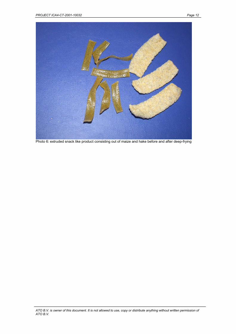
Photos 5 and 6 shown an extruded snack like product of maize grits and hake filet before(left) and after (right) deep-frying. Further research at the extrusion of direct expandedproducts consisting out of fish and flour will be done with the prototype and desirable rawmaterials.
Photo 5: extruded snack like product consisting out of maize and hake before and after deep-frying.
PROJECT ICA4-CT-2001-10032 Page 12
ATO B.V. is owner of this document. It is not allowed to use, copy or distribute anything without written permission ofATO B.V.
Photo 6: extruded snack like product consisting out of maize and hake before and after deep-frying

PROJECT ICA4-CT-2001-10032
ATO B.V. is owner of this document. It is not allowed to use, copy or distribute anything without written permission ofATO B.V.
ANNEX; overall drawings of the designed extruder

PROJECT ICA4-CT-2001-10032 Annex Page 1
ATO B.V. is owner of this document. It is not allowed to use, copy or distribute anything without written permission ofATO B.V.
Figure 1: schematic overview of the extruder

PROJECT ICA4-CT-2001-10032 Annex Page 2
ATO B.V. is owner of this document. It is not allowed to use, copy or distribute anything without written permission ofATO B.V.
Figure 2: Overview of the critical points