panel descriptions about plug-in/plug-out -...

1
English Owner’s Manual About Plug-In/Plug-Out When you turn on the [SYSTEM-1] button, this unit operates as a SYSTEM-1 synthesizer. When you turn on the [PLUG-OUT] button, this unit operates as a “plug-out” synthesizer. What is “plug-out”? A separately sold plug-out compatible software synthesizer can be downloaded to this unit, allowing you to play this unit by itself. The plug-out compatible software synthesizer can also be used as a plug-in synthesizer on your computer. For details on dedicated plug-out software synthesizers and how to obtain them, and on the operating requirements, refer to the Roland website. &http://roland.cm/system1 Synchronizing/Recording with Other Devices The SYSTEM-1 can receive MIDI Clock (F8) data to synchronize its tempo. Synchronizing with a TR-8 You can synchronize the SYSTEM-1 with a TR-8 by using a commercially available MIDI cable to make connections. Synchronizing/recording with your computer DAW via USB If you use a commercially available USB 2.0 cable to connect the SYSTEM-1 to your computer, you can synchronize the SYSTEM-1 with your DAW via USB MIDI, or record the sound of the SYSTEM-1 onto tracks of your DAW via USB audio. TR-8 (master) SYSTEM-1 (slave) MIDI OUT MIDI IN Various Settings Restoring the Factory Settings (Factory Reset) Here’s how to return the SYSTEM-1 to its factory-set state. 1. While holding down the [MANUAL] button, turn on the power. The [ARPEGGIO] button blinks. If you decide to cancel the factory reset, turn off the power. 2. Press the [ARPEGGIO] button to execute the factory reset. 3. When all buttons lit, turn the SYSTEM-1’s power off, then on again. MIDI and Other Settings 1. While holding down the [SYSTEM-1] button, turn on the power. The [ARPEGGIO] button blinks. If you decide not to make settings, turn off the power. 2. Use the [1]–[3] buttons and the SCATTER [TYPE] dial to change the settings. Parameter Controller Explanation MIDI channel [TYPE] dial Unlit (OFF) Specifies the MIDI transmit/receive channel. The SCATTER LEDs (1–10) indicate the channel. (default: 1) All unlit (OFF) when turned to the far left All lit (OMNI) when turned to the far right For 11–16, LEDs 10 and 1–6 are lit simultaneously. 1–16 All lit (OMNI) MIDI messages of all channels are received. The MIDI transmit channel will be 1. MIDI Clock Source [1] button Lit (AUTO) If MIDI clock is being input to the MIDI IN connector or the USB port, the SYSTEM-1’s tempo will automatically synchronize to MIDI clock. (default) * If MIDI clock is being simultaneously input from the MIDI IN connector and from the USB port, the USB port takes priority. Unlit (INTERNAL) The SYSTEM-1 operates at the tempo specified on the unit itself. Choose the “INTERNAL” setting if you don’t want to synchronize to an external device. MIDI Thru [2] button Lit (ON) Specifies whether data received from the MIDI IN connector will be retransmitted from the MIDI OUT connector (ON: default) or will not be retransmitted (OFF). Unlit (OFF) BOOST mode [3] button Lit (ON) Boosts the output level of the OUT jacks. Unlit (OFF) LED DEMO Hold down [MOD] and turn the [TYPE] dial Specifies the time (minute) until the LED DEMO is shown. If this is unlit, the LED DEMO is not shown. 3. Press the [ARPEGGIO] button to save the settings. The settings are saved, and the SYSTEM-1 restarts. Main Specifications Roland SYSTEM-1: PLUG-OUT SYNTHESIZER Maximum Polyphony 4 voices (SYSTEM-1 Mode) Power Supply AC adaptor Current Draw 850 mA Dimensions 472 (W) x 283 (D) x 70 (H) mm 18-5/8 (W) x 11-3/16 (D) x 2-13/16 (H) inches Weight 2.4 kg (excluding AC adaptor) 5 lbs 5 oz Accessories AC adaptor, Owner’s Manual, Leaflet “USING THE UNIT SAFELY” Options (sold separately) Pedal switch: DP Series, Footswitch: BOSS FS-5U, Expression pedal: EV-5 * In the interest of product improvement, the specifications and/or appearance of this unit are subject to change without prior notice. Before using this unit, carefully read the leaflet “USING THE UNIT SAFELY.” The leaflet provides important information concerning the proper operation of the unit. Additionally, in order to feel assured that you have gained a good grasp of every feature of your new unit, read Owner’s Manual in its entirety. This manual should be saved and kept on hand as a convenient reference. Copyright © 2014 ROLAND CORPORATION All rights reserved. No part of this publication may be reproduced in any form without the written permission of ROLAND CORPORATION. 4 MIXER Here you can adjust the volume of OSC 1, OSC 2, the sub-oscillator (an oscillator that produces a sound one or two octaves lower), and noise. Controller Explanation [OSC 1] knob Adjusts the volume of the OSC 1. [OSC 2] knob Adjusts the volume of the OSC 2. [SUB OSC] knob Adjusts the volume of the sub oscillator. [OSC TYPE] button Selects the type of the sub oscillator. Lit: Sound one octave below, Unlit: Sound two octaves below [NOISE] knob Adjusts the volume of the noise. [NOISE TYPE] button Selects the type of the noise. Lit: white noise, Unlit: pink noise 5 PITCH Here you can create time-varying change (envelope) for pitch. Controller Explanation [ENV] knob If this knob is turned toward the right, the pitch initially becomes higher and then returns to the pitch of the key you pressed. If this knob is turned toward the left, the pitch initially becomes lower and then returns to the pitch of the key you pressed. [A] slider These sliders operate similarly to the [A][D] sliders of the 7 AMP section (they affect the pitch rather than the volume). [D] slider 6 FILTER These settings determine the brightness and thickness of the sound. Here you can also specify the time-varying change (envelope) for the filter. Controller Explanation [LPF CUTOFF] knob Specifies the cutoff frequency of the low-pass filter. Frequency components above the cutoff frequency are cut, making the sound mellower. [LPF TYPE] button Selects the slope (steepness) of the low-pass filter. Lit: -12 dB, Unlit: -24 dB [HPF CUTOFF] knob Specifies the cutoff frequency of the high-pass filter. Frequency components below the cutoff frequency are cut. [RESO] knob Resonance boosts the sound in the region of the filter’s cutoff frequency. Higher settings produce stronger emphasis, creating a distinctively “synthesizer-like” sound. [ENV] knob This knob specifies the depth and direction of the cutoff frequency change produced by the [A], [D], [S], and [R] sliders. If the knob is turned toward the right, the cutoff frequency moves in the upward direction. If the knob is turned toward the left, the cutoff frequency moves in the downward direction. [KEY] knob Allows the filter cutoff frequency to vary according to the key that you play. If the knob is turned toward the right, the cutoff frequency becomes higher as you play higher notes. If the knob is turned toward the left, the cutoff frequency becomes lower as you play lower notes. [A] slider These sliders operate similarly to the [A][D][S][R] sliders of the 7 AMP section (they affect the cutoff frequency rather than the volume). [D] slider [S] slider [R] slider 7 AMP Here you can create time-varying change (envelope) for the volume. Controller Explanation [TONE] knob Adjusts the brightness of the sound. [CRUSHER] knob Modifies the tonal character by distorting the waveform. [A] slider (Attack time) Specifies the time from the moment you press the key until the maximum volume is reached. [D] slider (Decay time) Specifies the time from when the maximum volume is reached, until it decays to the sustain level. [S] slider (Sustain level) Specifies the volume level that will be maintained from when the attack and decay times have elapsed until you release the key. [R] slider (Release time) Specifies the time from when you release the key until the volume reaches its minimum value. 8 EFFECTS Here you can adjust the amount of reverb and delay. Controller Explanation [REVERB] knob Adds reverberation. [DELAY] knob Adjusts the volume of delay sound. [TIME] knob Adjusts the delay time (the time by which the sound is delayed). 9 PITCH BEND/SCATTER “Pitch bend” modifies the pitch. What is Scatter? This is a function that applies various changes to the arpeggio performance, creating musical grooves. Controller Explanation [ARPEGGIO] button Causes an arpeggio to be produced when you simply hold down a chord on the keyboard. (This function is called the “arpeggiator.”) [ARP TYPE] knob Selects the arpeggio variation. [ARP STEP] knob Specifies the note value for each step of the arpeggiator. [PITCH BEND/ SCATTER] jog shuttle The jog shuttle normally operates as pitch bend. If the [ARPEGGIO] button is turned on, the jog shuttle adjusts the scatter depth. * Scatter is on while you operate the jog shuttle. When you return the jog shuttle to the center, scatter turns off. [TYPE] dial Selects the scatter type (1–10). [KEY HOLD] button You can make notes continue sounding even after you take your hand off the keyboard. Panel Descriptions 2 3 4 5 6 7 8 1 9 10 1 Common section Here you can make the following settings for the SYSTEM-1. Controller Explanation [VOLUME] knob Adjusts the volume. [PORTAMENTO] knob Creates a smooth change in pitch between one key and the next key played. The knob adjusts the time required for the pitch change. [LEGATO] button Applies portamento only when you play legato (i.e., when you press the next key before releasing the previous key). [TEMPO] knob Sets the tempo of the arpeggiator (scatter). The LED blinks at the tempo you specified. [TEMPO SYNC] button Synchronizes the RATE of the 2 LFO section and the delay time (TIME) of the 8 EFFECTS section to the tempo. [LFO KEY TRIG] button Specifies whether the LFO cycle will be synchronized to begin when the key is pressed (ON) or not (OFF). [MONO] button If this is on (lit), the synth will play monophonically (single notes). If this is blinking, the synth will play all sounds in unison (UNISON mode). MODEL [SYSTEM-1]/ [PLUG-OUT] button If the [SYSTEM-1] button is on, this unit will operate as a SYSTEM-1 synthesizer. If the [PLUG-OUT] button is on, this unit will operate in “plug-out” mode. &Refer to “About Plug-In/Plug-Out” [MANUAL] button Causes sound to be produced according to the current settings of the knobs and sliders. Memory[1]–[8] button Use these buttons to store/recall eight sets of panel settings (knobs/sliders). To store panel settings in a memory button Long-press a memory [1]–[8] button. To recall settings (a sound) from a memory button Press a memory [1]–[8] button. 2 LFO Here you can create cyclic change (modulation) in the sound by applying vibrato (pitch modulation) or tremolo (volume modulation). Controller Explanation Wave knob Selects the LFO waveform. R(Sine wave), S(Triangle wave), T(Sawtooth wave), U(Square wave), W(Sample and Hold), RND (Random wave) [FADE TIME] knob Specifies the time from when the tone sounds until the LFO reaches its maximum amplitude. [RATE] knob Determines the speed of the LFO. [PITCH] knob Allows the LFO to modulate the pitch, producing a vibrato effect. [FILTER] knob Allows the LFO to modulate the FILTER CUTOFF (cutoff frequency), [AMP] knob Allows the LFO to modulate the AMP LEVEL (volume), producing a tremolo effect. 3 OSC 1/OSC 2 Here you can select the waveform that determines the character of the sound, and specify its pitch. The SYSTEM-1 has two oscillators (OSC 1 and OSC 2). Controller Explanation Wave knob Selects the waveform that is the basis of the sound. T(Sawtooth wave), U(Square wave), S(Triangle wave), (Sawtooth wave 2), (Square wave 2), (Triangle wave 2) [COLOR] knob The result depends on the waveform. [MOD] knob Selects the source that modulates the [COLOR] knob. MAN The sound is determined by the position of the [COLOR] knob. It will not vary over time. LFO The sound varies over time at the rate specified in the 2 LFO section. P. ENV The sound changes over time according to the envelope of the 5 PITCH section. F. ENV The sound changes over time according to the envelope of the 6 FILTER section. A. ENV The sound changes over time according to the envelope of the 7 AMP section. S. OSC The sound changes over time according to the frequency of the sub-oscillator. Octave (feet) knob Specifies the octave of the oscillator. [CROSS MOD] knob Modifies the OSC 1 frequency according to the OSC 2 waveform. Turning the knob toward the right makes OSC 1 become a more complex sound, allowing you to create metallic sounds or sound effects. [TUNE] knob Adjusts the pitch of the oscillator. Coarse Tune Adjusts the pitch in semitone steps. By holding down the [RING][SYNC] buttons simultaneously and turning the SCATTER [TYPE] dial, you can adjust the Coarse Tune. The SCATTER LEDs (1–10) indicate the amount of Coarse Tune (OFF (unlit), -11–+11). (LEDs 10 and 1 light simultaneously to indicate 11.) [RING] button This is a ring modulator. It generates a complex waveform by multiplying OSC 1 and OSC 2. [SYNC] button This is oscillator sync. It generates a complex waveform by forcibly resetting OSC 2 to the beginning of its cycle in synchronization with the OSC 1 frequency. Controller Explanation OCTAVE [DOWN] [UP] button Octave shift You can shift the keyboard’s pitch range in steps of one octave. The button is lit for the one octave setting; the button is blinking for the 2–3 octave setting. If you press the [DOWN] [UP] buttons simultaneously, the keyboard will return to its normal pitch range. Key transpose By holding down the [DOWN][UP] buttons simultaneously and turning the SCATTER [TYPE] dial, you can transpose the keyboard in semitone steps (only upward). The SCATTER LEDs (1–10) indicate the amount of transposition (1–11). (LEDs 10 and 1 light simultaneously to indicate 11.) All unlit (OFF) when turned to the far left [MOD] button Vibrato (modulation) is applied to the sound while you hold down the [MOD] button. By holding down the [MOD] button and operating the 2 LFO section, you can adjust the MOD depth. 10 Keyboard This is a standard-size keyboard. It is not touch-sensitive (the velocity is fixed). Connecting Your Equipment * To prevent malfunction and equipment failure, always turn down the volume, and turn off all the units before making any connections. A B C E F G D H A DC IN jack Connect the included AC adaptor here. Use only the included AC adaptor. * To prevent the inadvertent disruption of power to your unit (should the plug be pulled out accidentally), and to avoid applying undue stress to the DC IN jack, anchor the power cord using the cord hook, as shown in the illustration. B USB ( ) port Use a commercially available USB 2.0 cable to connect this port to your computer. It can be used to transfer USB MIDI and USB audio data. You must install the USB driver before connecting the SYSTEM-1 to your computer. Download the USB driver from the Roland website. For details, refer to Readme.htm which is included in the download. &http://www.roland.com/support/ C MIDI connectors For connecting MIDI device. D Security slot ( ) &http://www.kensington.com/ E PEDAL jacks If you connect a pedal switch (DP series, BOSS FS-5U; sold separately) to the HOLD jack, the notes will be sustained as long as you continue holding down the pedal even after you take your hands off the keyboard. If you connect an expression pedal (EV-5; sold separately) to the CONTROL jack, you’ll be able to use the expression pedal to control the volume and add expression to your performance. * Use only the specified expression pedal (EV-5; sold separately). By connecting any other expression pedals, you risk causing malfunction and/or damage to the unit. F OUT jacks Connect these jacks to your amp or monitor speakers. If your system is monaural, use only the L/MONO jack. G PHONES jack Connect headphones (sold separately) here. Turning the Power On/Off H [POWER] switch This turns the power on/off. * After you’ve made connections correctly, be sure to turn on the power in the order of the SYSTEM-1 first, and then the connected system. Powering-on in the incorrect order may cause malfunctions or damage. When turning the power off, power-off the connected system first, and then the SYSTEM-1. * This unit is equipped with a protection circuit. A brief interval (a few seconds) after turning the unit on is required before it will operate normally. * Before turning the unit on/off, always be sure to turn the volume down. Even with the volume turned down, you might hear some sound when switching the unit on/off. However, this is normal and does not indicate a malfunction.

Upload: truongcong

Post on 23-Apr-2018

218 views

Category:

Documents


1 download

TRANSCRIPT

EnglishOwner’s Manual

About Plug-In/Plug-OutWhen you turn on the [SYSTEM-1] button, this unit operates as a SYSTEM-1 synthesizer. When you turn on the [PLUG-OUT] button, this unit operates as a “plug-out” synthesizer.

What is “plug-out”?• A separately sold plug-out compatible software synthesizer can be

downloaded to this unit, allowing you to play this unit by itself.• The plug-out compatible software synthesizer can also be used as a plug-in synthesizer on your computer.• For details on dedicated plug-out software synthesizers and how to obtain them, and

on the operating requirements, refer to the Roland website.& http://roland.cm/system1

Synchronizing/Recording with Other DevicesThe SYSTEM-1 can receive MIDI Clock (F8) data to synchronize its tempo.

Synchronizing with a TR-8You can synchronize the SYSTEM-1 with a TR-8 by using a commercially available MIDI cable to make connections.

Synchronizing/recording with your computer DAW via USBIf you use a commercially available USB 2.0 cable to connect the SYSTEM-1 to your computer, you can synchronize the SYSTEM-1 with your DAW via USB MIDI, or record the sound of the SYSTEM-1 onto tracks of your DAW via USB audio.

TR-8 (master) SYSTEM-1 (slave)

MIDI OUT MIDI IN

Various Settings

Restoring the Factory Settings (Factory Reset)Here’s how to return the SYSTEM-1 to its factory-set state.1. While holding down the [MANUAL] button, turn on the power.

The [ARPEGGIO] button blinks. If you decide to cancel the factory reset, turn off the power.

2. Press the [ARPEGGIO] button to execute the factory reset.

3. When all buttons lit, turn the SYSTEM-1’s power off, then on again.

MIDI and Other Settings

1. While holding down the [SYSTEM-1] button, turn on the power.The [ARPEGGIO] button blinks. If you decide not to make settings, turn off the power.

2. Use the [1]–[3] buttons and the SCATTER [TYPE] dial to change the settings.

Parameter Controller Explanation

MIDI channel [TYPE] dial

Unlit (OFF) Specifies the MIDI transmit/receive channel. The SCATTER LEDs (1–10) indicate the channel. (default: 1)

• All unlit (OFF) when turned to the far left• All lit (OMNI) when turned to the far right• For 11–16, LEDs 10 and 1–6 are lit simultaneously.

1–16

All lit (OMNI)MIDI messages of all channels are received. The MIDI transmit channel will be 1.

MIDI Clock Source [1] button

Lit (AUTO)

If MIDI clock is being input to the MIDI IN connector or the USB port, the SYSTEM-1’s tempo will automatically synchronize to MIDI clock. (default)

* If MIDI clock is being simultaneously input from the MIDI IN connector and from the USB port, the USB port takes priority.

Unlit (INTERNAL)

The SYSTEM-1 operates at the tempo specified on the unit itself. Choose the “INTERNAL” setting if you don’t want to synchronize to an external device.

MIDI Thru [2] buttonLit (ON) Specifies whether data received from the MIDI IN connector will be

retransmitted from the MIDI OUT connector (ON: default) or will not be retransmitted (OFF).Unlit (OFF)

BOOST mode [3] button

Lit (ON) Boosts the output level of the OUT jacks.

Unlit (OFF)

LED DEMO Hold down [MOD] and turn the [TYPE] dial

Specifies the time (minute) until the LED DEMO is shown. If this is unlit, the LED DEMO is not shown.

3. Press the [ARPEGGIO] button to save the settings.The settings are saved, and the SYSTEM-1 restarts.

Main Specifications Roland SYSTEM-1: PLUG-OUT SYNTHESIZER

Maximum Polyphony 4 voices (SYSTEM-1 Mode)Power Supply AC adaptorCurrent Draw 850 mADimensions 472 (W) x 283 (D) x 70 (H) mm 18-5/8 (W) x 11-3/16 (D) x 2-13/16 (H) inchesWeight 2.4 kg (excluding AC adaptor) 5 lbs 5 ozAccessories AC adaptor, Owner’s Manual, Leaflet “USING THE UNIT SAFELY”Options (sold separately)

Pedal switch: DP Series, Footswitch: BOSS FS-5U, Expression pedal: EV-5

* In the interest of product improvement, the specifications and/or appearance of this unit are subject to change without prior notice.

Before using this unit, carefully read the leaflet “USING THE UNIT SAFELY.” The leaflet provides important information concerning the proper operation of the unit. Additionally, in order to feel assured that you have gained a good grasp of every feature of your new unit, read Owner’s Manual in its entirety. This manual should be saved and kept on hand as a convenient reference.

Copyright © 2014 ROLAND CORPORATIONAll rights reserved. No part of this publication may be reproduced in any form without the written permission of ROLAND CORPORATION.

4 MIXERHere you can adjust the volume of OSC 1, OSC 2, the sub-oscillator (an oscillator that produces a sound one or two octaves lower), and noise.

Controller Explanation[OSC 1] knob Adjusts the volume of the OSC 1.[OSC 2] knob Adjusts the volume of the OSC 2.[SUB OSC] knob Adjusts the volume of the sub oscillator.

[OSC TYPE] button Selects the type of the sub oscillator.Lit: Sound one octave below, Unlit: Sound two octaves below

[NOISE] knob Adjusts the volume of the noise.[NOISE TYPE] button

Selects the type of the noise.Lit: white noise, Unlit: pink noise

5 PITCHHere you can create time-varying change (envelope) for pitch.

Controller Explanation

[ENV] knob

If this knob is turned toward the right, the pitch initially becomes higher and then returns to the pitch of the key you pressed.If this knob is turned toward the left, the pitch initially becomes lower and then returns to the pitch of the key you pressed.

[A] slider These sliders operate similarly to the [A][D] sliders of the 7 AMP section (they affect the pitch rather than the volume).[D] slider

6 FILTERThese settings determine the brightness and thickness of the sound. Here you can also specify the time-varying change (envelope) for the filter.

Controller Explanation

[LPF CUTOFF] knob Specifies the cutoff frequency of the low-pass filter. Frequency components above the cutoff frequency are cut, making the sound mellower.

[LPF TYPE] buttonSelects the slope (steepness) of the low-pass filter.Lit: -12 dB, Unlit: -24 dB

[HPF CUTOFF] knob

Specifies the cutoff frequency of the high-pass filter. Frequency components below the cutoff frequency are cut.

[RESO] knobResonance boosts the sound in the region of the filter’s cutoff frequency.Higher settings produce stronger emphasis, creating a distinctively “synthesizer-like” sound.

[ENV] knob

This knob specifies the depth and direction of the cutoff frequency change produced by the [A], [D], [S], and [R] sliders.If the knob is turned toward the right, the cutoff frequency moves in the upward direction.If the knob is turned toward the left, the cutoff frequency moves in the downward direction.

[KEY] knob

Allows the filter cutoff frequency to vary according to the key that you play.If the knob is turned toward the right, the cutoff frequency becomes higher as you play higher notes.If the knob is turned toward the left, the cutoff frequency becomes lower as you play lower notes.

[A] slider

These sliders operate similarly to the [A][D][S][R] sliders of the 7 AMP section (they affect the cutoff frequency rather than the volume).

[D] slider[S] slider[R] slider

7 AMPHere you can create time-varying change (envelope) for the volume.

Controller Explanation[TONE] knob Adjusts the brightness of the sound.[CRUSHER] knob Modifies the tonal character by distorting the waveform.[A] slider (Attack time)

Specifies the time from the moment you press the key until the maximum volume is reached.

[D] slider (Decay time)

Specifies the time from when the maximum volume is reached, until it decays to the sustain level.

[S] slider (Sustain level)

Specifies the volume level that will be maintained from when the attack and decay times have elapsed until you release the key.

[R] slider (Release time)

Specifies the time from when you release the key until the volume reaches its minimum value.

8 EFFECTSHere you can adjust the amount of reverb and delay.

Controller Explanation[REVERB] knob Adds reverberation.[DELAY] knob Adjusts the volume of delay sound.[TIME] knob Adjusts the delay time (the time by which the sound is delayed).

9 PITCH BEND/SCATTER“Pitch bend” modifies the pitch.

What is Scatter?This is a function that applies various changes to the arpeggio performance, creating musical grooves.

Controller Explanation

[ARPEGGIO] button Causes an arpeggio to be produced when you simply hold down a chord on the keyboard. (This function is called the “arpeggiator.”)

[ARP TYPE] knob Selects the arpeggio variation.[ARP STEP] knob Specifies the note value for each step of the arpeggiator.

[PITCH BEND/SCATTER] jog shuttle

The jog shuttle normally operates as pitch bend.If the [ARPEGGIO] button is turned on, the jog shuttle adjusts the scatter depth.

* Scatter is on while you operate the jog shuttle. When you return the jog shuttle to the center, scatter turns off.

[TYPE] dial Selects the scatter type (1–10).[KEY HOLD] button You can make notes continue sounding even after you take your hand off the keyboard.

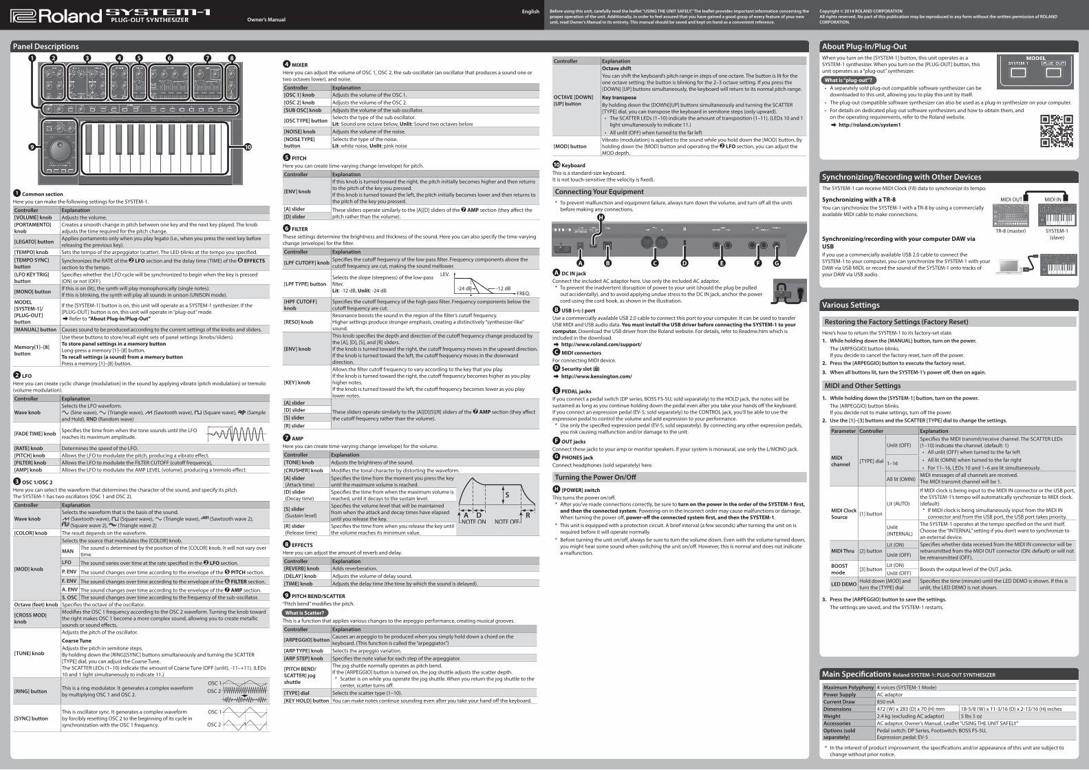
Panel Descriptions2 3 4 5 6 7 81

9 10

1 Common sectionHere you can make the following settings for the SYSTEM-1.

Controller Explanation[VOLUME] knob Adjusts the volume.[PORTAMENTO] knob

Creates a smooth change in pitch between one key and the next key played. The knob adjusts the time required for the pitch change.

[LEGATO] button Applies portamento only when you play legato (i.e., when you press the next key before releasing the previous key).

[TEMPO] knob Sets the tempo of the arpeggiator (scatter). The LED blinks at the tempo you specified.[TEMPO SYNC] button

Synchronizes the RATE of the 2 LFO section and the delay time (TIME) of the 8 EFFECTS section to the tempo.

[LFO KEY TRIG] button

Specifies whether the LFO cycle will be synchronized to begin when the key is pressed (ON) or not (OFF).

[MONO] button If this is on (lit), the synth will play monophonically (single notes).If this is blinking, the synth will play all sounds in unison (UNISON mode).

MODEL [SYSTEM-1]/[PLUG-OUT] button

If the [SYSTEM-1] button is on, this unit will operate as a SYSTEM-1 synthesizer. If the [PLUG-OUT] button is on, this unit will operate in “plug-out” mode.&Refer to “About Plug-In/Plug-Out”

[MANUAL] button Causes sound to be produced according to the current settings of the knobs and sliders.

Memory[1]–[8] button

Use these buttons to store/recall eight sets of panel settings (knobs/sliders).To store panel settings in a memory buttonLong-press a memory [1]–[8] button.To recall settings (a sound) from a memory buttonPress a memory [1]–[8] button.

2 LFOHere you can create cyclic change (modulation) in the sound by applying vibrato (pitch modulation) or tremolo (volume modulation).

Controller Explanation

Wave knobSelects the LFO waveform.R (Sine wave), S (Triangle wave), T (Sawtooth wave), U (Square wave), W (Sample and Hold), RND (Random wave)

[FADE TIME] knob Specifies the time from when the tone sounds until the LFO reaches its maximum amplitude.

[RATE] knob Determines the speed of the LFO.[PITCH] knob Allows the LFO to modulate the pitch, producing a vibrato effect.[FILTER] knob Allows the LFO to modulate the FILTER CUTOFF (cutoff frequency),[AMP] knob Allows the LFO to modulate the AMP LEVEL (volume), producing a tremolo effect.

3 OSC 1/OSC 2Here you can select the waveform that determines the character of the sound, and specify its pitch. The SYSTEM-1 has two oscillators (OSC 1 and OSC 2).

Controller Explanation

Wave knobSelects the waveform that is the basis of the sound.T (Sawtooth wave), U (Square wave), S (Triangle wave), (Sawtooth wave 2),

(Square wave 2), (Triangle wave 2) [COLOR] knob The result depends on the waveform.

[MOD] knob

Selects the source that modulates the [COLOR] knob.

MAN The sound is determined by the position of the [COLOR] knob. It will not vary over time.

LFO The sound varies over time at the rate specified in the 2 LFO section.

P. ENV The sound changes over time according to the envelope of the 5 PITCH section.

F. ENV The sound changes over time according to the envelope of the 6 FILTER section.A. ENV The sound changes over time according to the envelope of the 7 AMP section.S. OSC The sound changes over time according to the frequency of the sub-oscillator.

Octave (feet) knob Specifies the octave of the oscillator.

[CROSS MOD] knob

Modifies the OSC 1 frequency according to the OSC 2 waveform. Turning the knob toward the right makes OSC 1 become a more complex sound, allowing you to create metallic sounds or sound effects.

[TUNE] knob

Adjusts the pitch of the oscillator.

Coarse TuneAdjusts the pitch in semitone steps.By holding down the [RING][SYNC] buttons simultaneously and turning the SCATTER [TYPE] dial, you can adjust the Coarse Tune.The SCATTER LEDs (1–10) indicate the amount of Coarse Tune (OFF (unlit), -11–+11). (LEDs 10 and 1 light simultaneously to indicate 11.)

[RING] button This is a ring modulator. It generates a complex waveform by multiplying OSC 1 and OSC 2.

[SYNC] buttonThis is oscillator sync. It generates a complex waveform by forcibly resetting OSC 2 to the beginning of its cycle in synchronization with the OSC 1 frequency.

Controller Explanation

OCTAVE [DOWN] [UP] button

Octave shiftYou can shift the keyboard’s pitch range in steps of one octave. The button is lit for the one octave setting; the button is blinking for the 2–3 octave setting. If you press the [DOWN] [UP] buttons simultaneously, the keyboard will return to its normal pitch range.

Key transposeBy holding down the [DOWN][UP] buttons simultaneously and turning the SCATTER [TYPE] dial, you can transpose the keyboard in semitone steps (only upward).

• The SCATTER LEDs (1–10) indicate the amount of transposition (1–11). (LEDs 10 and 1 light simultaneously to indicate 11.)

• All unlit (OFF) when turned to the far left

[MOD] buttonVibrato (modulation) is applied to the sound while you hold down the [MOD] button. By holding down the [MOD] button and operating the 2 LFO section, you can adjust the MOD depth.

10 KeyboardThis is a standard-size keyboard.It is not touch-sensitive (the velocity is fixed).

Connecting Your Equipment* To prevent malfunction and equipment failure, always turn down the volume, and turn off all the units

before making any connections.

A B C E F GD

H

A DC IN jackConnect the included AC adaptor here. Use only the included AC adaptor.

* To prevent the inadvertent disruption of power to your unit (should the plug be pulled out accidentally), and to avoid applying undue stress to the DC IN jack, anchor the power cord using the cord hook, as shown in the illustration.

B USB ( ) portUse a commercially available USB 2.0 cable to connect this port to your computer. It can be used to transfer USB MIDI and USB audio data. You must install the USB driver before connecting the SYSTEM-1 to your computer. Download the USB driver from the Roland website. For details, refer to Readme.htm which is included in the download.& http://www.roland.com/support/C MIDI connectors

For connecting MIDI device.D Security slot ( )& http://www.kensington.com/

E PEDAL jacksIf you connect a pedal switch (DP series, BOSS FS-5U; sold separately) to the HOLD jack, the notes will be sustained as long as you continue holding down the pedal even after you take your hands off the keyboard.If you connect an expression pedal (EV-5; sold separately) to the CONTROL jack, you’ll be able to use the expression pedal to control the volume and add expression to your performance.

* Use only the specified expression pedal (EV-5; sold separately). By connecting any other expression pedals, you risk causing malfunction and/or damage to the unit.

F OUT jacksConnect these jacks to your amp or monitor speakers. If your system is monaural, use only the L/MONO jack.G PHONES jack

Connect headphones (sold separately) here.

Turning the Power On/OffH [POWER] switch

This turns the power on/off.* After you’ve made connections correctly, be sure to turn on the power in the order of the SYSTEM-1 first,

and then the connected system. Powering-on in the incorrect order may cause malfunctions or damage. When turning the power off, power-off the connected system first, and then the SYSTEM-1.

* This unit is equipped with a protection circuit. A brief interval (a few seconds) after turning the unit on is required before it will operate normally.

* Before turning the unit on/off, always be sure to turn the volume down. Even with the volume turned down, you might hear some sound when switching the unit on/off. However, this is normal and does not indicate a malfunction.