pac-man battle royale operation manual...pac-man battle royale operation manual to ensure safe...
TRANSCRIPT

PAC-MAN BATTLE ROYALEOPERATION MANUAL
To ensure safe operation of the game machine, be sure to read this Operation Manual before use.Keep this Operation Manual in a safe place for quick access whenever needed.
The actual product may differ slightly from the illustrations in this manual.
Specifications of the machine and contents of this operation manual are subject to change without prior notice due to product improvements.
WARNING
PAC-MAN BATTLE ROYALE
Operation M
anual
Part No. PG45-13396-00First Edition Published in January 2011

INTRODUCTIONThank you for purchasing the “PAC-MAN BATTLE ROYALE” game machine (hereinafter referred to as the “machine”).
This operation manual describes:●Howto install,operate, relocate, transport,service,anddiscard themachinesafely
and properly●Howtooperatethemachinecorrectlyandmakefulluseofitsfeatures●Howtoensurethesafetyofplayersandbystanders
Inquiries regarding this machine and its repair●Forfurtherinformationaboutthemachineanditsrepair,contactyourdistributor.
Thesoftware included in themachine isprotectedbycopyright laws.Thesoftwaremaynotbecopied,modified,distributedpublicly,orusedforpurposesotherthantheoperationofthisgamemachine.Violatorsofcopyright lawsmaybesubject tocriminalpenalties.Donotusethestoragemediacontainingsoftwareinanyothergamemachine;doingsomaycausethatmachine to malfunction.
Thismachineusesthefollowinglicenses.
Fontsusedin-gameareprovidedbyBitstreamInc.Allrightsreserved.
Copyright©1997-2002,MakotoMatsumotoandTakujiNishimura,Allrightsreserved.
Redistributionanduseinsourceandbinaryforms,withorwithoutmodification,arepermittedprovidedthatthefollowingconditionsaremet:
1.Redistributionsofsourcecodemustretaintheabovecopyrightnotice,thislistofconditionsandthefollowingdisclaimer.
2.Redistributions in binary formmust reproduce theabove copyright notice, this list ofconditionsandthefollowingdisclaimerinthedocumentationand/orothermaterialsprovidedwiththedistribution.
3.Thenamesofitscontributorsmaynotbeusedtoendorseorpromoteproductsderivedfromthissoftwarewithoutspecificpriorwrittenpermission.
THISSOFTWAREISPROVIDEDBYTHECOPYRIGHTHOLDERSANDCONTRIBUTORS“AS IS”ANDANYEXPRESSOR IMPLIEDWARRANTIES, INCLUDING,BUTNOTLIMITEDTO,THEIMPLIEDWARRANTIESOFMERCHANTABILITYANDFITNESSFORAPARTICULARPURPOSEAREDISCLAIMED.INNOEVENTSHALLTHECOPYRIGHTOWNERORCONTRIBUTORSBELIABLEFORANYDIRECT, INDIRECT, INCIDENTAL,SPECIAL,EXEMPLARY,ORCONSEQUENTIALDAMAGES (INCLUDING,BUTNOTLIMITEDTO,PROCUREMENTOFSUBSTITUTEGOODSORSERVICES;LOSSOFUSE,DATA,ORPROFITS;ORBUSINESS INTERRUPTION)HOWEVERCAUSEDANDONANYTHEORYOFLIABILITY,WHETHER INCONTRACT,STRICTLIABILITY,ORTORT(INCLUDINGNEGLIGENCEOROTHERWISE)ARISINGINANYWAYOUTOFTHEUSEOFTHISSOFTWARE,EVENIFADVISEDOFTHEPOSSIBILITYOFSUCHDAMAGE.

Test mode
TroubleshootingMagnitudes of risk/Definition of “technician”
1
1. SAFETY PRECAUTIONS – Be sure to read this section before installing or operating the machine. –
Instructions to the ownerIf you entrust another party to perform installation, operation, relocation, ztransportation, service, or discarding of the machine, instruct the concerned party to read and observe all the instructions and precautions in this operation manual regarding the particular action to be taken.
1-1 Magnitudes of riskOn the labels attached to the machine and in this operation manual, precautions regarding safety and property damage are classified as shown below in accordance with the magnitude of the particular risk.
WARNING : Failure to avoid the indicated risk may result in death or serious injury.
CAUTION : Failure to avoid the indicated risk may result in minor injury or property damage.
Notes related to machine functions but not to safety are marked with the following indication.
● Note related to product function or protection.
1-2 Definition of “technician”This operation manual is written for arcade personnel. However, the sections marked “To be conducted by a technician only” in the table of contents are written for technicians. These tasks should be conducted by technicians only.
Technician: A person engaged in machine design, manufacture, inspection or service for a manufacturer of amusement equipment, or a person who has technical knowledge related to electricity, electronics or mechanical engineering at a level equal to or higher than that of a technical high school graduate and who is engaged routinely in the service and management (including repair) of amusement machines.

1. SAFETY PRECAUTIONS
2
1-3 Critical safety precautions
WARNINGShould any abnormality occur, turn off the power switch immediately to stop zzoperating the machine. Then, unplug the power cord plug from the AC outlet. Operating the machine without correcting abnormalities can result in a fire or accident.Some monitor sections remain hot or charged with high voltage even after the power zzswitch is turned off. Do not touch the monitor unnecessarily in order to avoid electric shock and burns.Dust accumulated on the power cord plug may cause a fire. Check the power cord zzplug regularly and remove dust.Insert the power cord plug firmly into the AC outlet. Poor contact may cause zzoverheating that can lead to a fire or burns.A damaged power cord can cause a fire, electric shock or electrical leakage. Observe zzthe following cautions.
Keep the power cord away from heating devices. •Do not twist the power cord. •Do not bend the power cord forcibly. •Do not alter the power cord. •Do not bundle the power cord. •Do not pull the power cord. (Always unplug by holding the power cord plug, and •avoid pulling the power cord.)Do not place anything on the power cord. •Do not allow the power cord to be caught under or between the machine, other •equipment or the wall.Do not do anything else that might damage the power cord. •
Do not wet the power cord or power cord plug with water. Water can cause an electric zzshock or electrical leakage.Do not touch the power cord plug with a wet hand. Doing so can result in an electric zzshock.The machine’s rated power supply voltage and maximum consumption current are zz120 V AC, 2 A, respectively. To prevent fire and electric shock, be sure to use interior wiring that conforms to these power supply specifications.Operate the machine with a power supply voltage in the range of 104 to 127 V AC. zzOperating the machine with a supply voltage outside the specified range may cause a fire or electric shock. To ensure that the machine operates in optimum condition, maintain the power supply at 120 V AC.To ensure safe operation of the machine, be sure to conduct the pre-service check zz(See P. 15 “7-1 Pre-service check”) and service (See P. 44 “8B. SERVICES”) described in this manual. Failure to conduct the pre-service check or service can result in an accident.Use consumables and service parts (including fasteners) specified by our company. zzTo order parts, contact your distributor.Do not convert the machine without permission. Do not perform any work that is not zzdescribed in this operation manual. Unauthorized conversion of the machine may create unforeseen hazards.When transferring ownership of the machine, be sure to provide this operation zzmanual with the game machine.

1. SAFETY PRECAUTIONS
Test mode
TroubleshootingCritical safety precautions/ Description of warning labels attached to the machine
3
1-4 Description of warning labels attached to the machine
WARNINGThe warning labels describe important safety precautions. Be sure to observe the zzfollowing:
To ensure that the warning labels attached to the machine are easily legible, install •the machine at an appropriate location with ample illumination and keep the labels clean at all times. Also, make sure that the labels are not hidden behind another game machine or other objects.Do not remove or alter the warning labels. •If the warning labels become excessively dirty or damaged, replace them with new •labels. To order warning labels, contact your distributor.
Warning labels

4
CONTENTSINTRODUCTION
1. SAFETY PRECAUTIONS – Be sure to read this section before installing or operating the machine. – ..................................................................... 11-1 Magnitudes of risk........................................................................................................................................... 11-2 Definitionof“technician” ................................................................................................................................. 11-3 Criticalsafetyprecautions............................................................................................................................... 21-4 Descriptionofwarninglabelsattachedtothemachine .................................................................................. 3
2. SPECIFICATIONS ...................................................................................................................................... 6
3. PACKAGE CONTENTS ............................................................................................................................. 8
4. OVERALL CONSTRUCTION (Names of Parts) ....................................................................................... 9
5. INSTALLATION .........................................................................................................................................105-1 Installationconditions ................................................................................................................................... 10
5-1-1 Locationstoavoidwheninstallingthemachine .................................................................................. 105-1-2 Playzoneforinstalledmachine .......................................................................................................... 11
5-2 Requireddimensionsforbringingthemachineinside(suchasdoorsandcorridors) .................................. 11
6. MOVING AND TRANSPORTING .............................................................................................................126-1 Moving(onthefloor) ..................................................................................................................................... 126-2 Transportation ............................................................................................................................................... 13
6-2-1 Manualtransportation(carryingonstairs,etc.) .................................................................................. 13
7. OPERATION ..............................................................................................................................................147-1 Pre-servicecheck ......................................................................................................................................... 15
7-1-1 Safetycheck(beforepowerON) ........................................................................................................ 157-1-2 Operationcheck(afterpowerON) ...................................................................................................... 16
7-2 Explanationofthepowerswitchandadjustmentswitches ........................................................................... 177-2-1 Turningthepowerswitchon ............................................................................................................... 177-2-2 Adjustmentswitchesandbuttons ....................................................................................................... 18
7-3 HowtoplayPAC-MANBATTLEROYALE .................................................................................................... 197-3-1 Gamerules ......................................................................................................................................... 197-3-2 HowtocontrolyourPac-Man ............................................................................................................. 197-3-3 Itemsandastrategyinthemaze........................................................................................................ 197-3-4 STARTbutton ..................................................................................................................................... 20
7-4 Testmode ..................................................................................................................................................... 217-4-1 Descriptionofthemenuscreen(MENU) ............................................................................................ 217-4-2 Gamefeesettings(COINOPTIONS) .................................................................................................227-4-3 Gamedetailsettings(GAMEOPTIONS) ............................................................................................ 247-4-4 Switch/sensortest(I/OTEST) ............................................................................................................ 25
(1) SWITCHTEST .............................................................................................................................. 26(2)OUTPUTTEST ............................................................................................................................. 27
7-4-5 Monitorconditiontest(MONITORTEST) ........................................................................................... 287-4-6 Soundadjustment(SOUNDTEST) .................................................................................................... 297-4-7 Gamedatadisplay/initialization(BOOKKEEPING).............................................................................30
(1) ERRORLOG ................................................................................................................................ 317-4-8 Initializationandothersettings(OTHERS) ......................................................................................... 32
(1) CLOCKSETTING .........................................................................................................................33(2)BACKUPMEMORYINITIALIZE ...................................................................................................34
7-5 Errordisplay(forthearcadeoperator) .......................................................................................................... 35
Test mode
Troubleshooting
CONTENTS
5
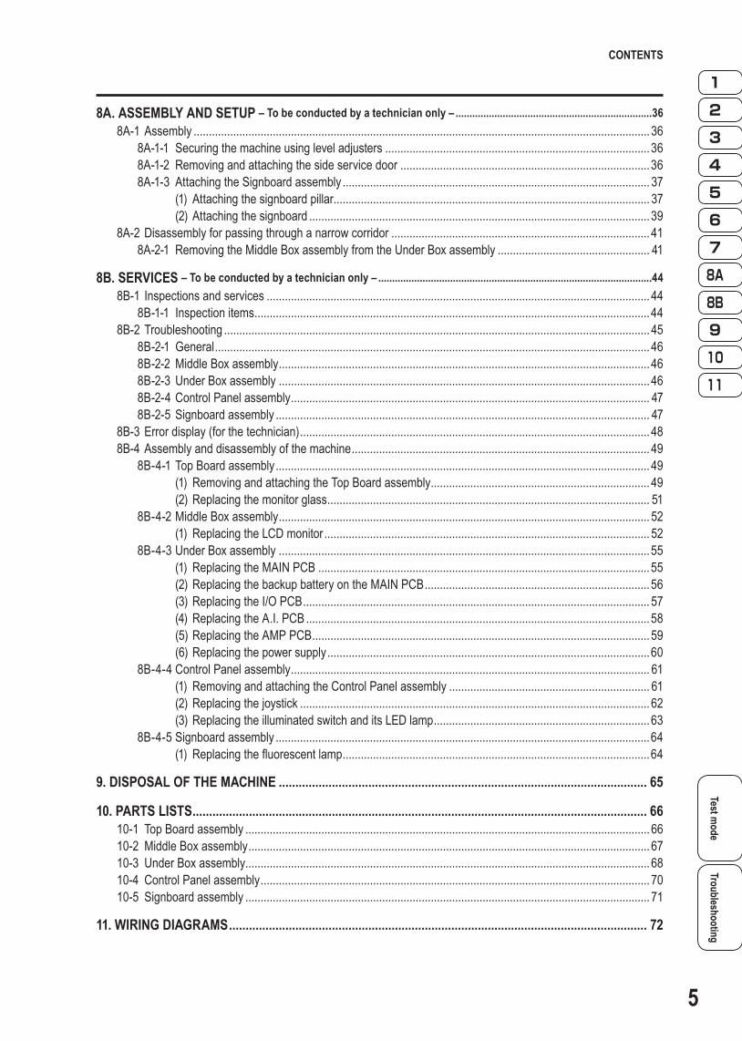
8A. ASSEMBLY AND SETUP – To be conducted by a technician only – .......................................................................368A-1Assembly ...................................................................................................................................................... 36
8A-1-1 Securingthemachineusingleveladjusters .......................................................................................368A-1-2 Removingandattachingthesideservicedoor ..................................................................................368A-1-3 AttachingtheSignboardassembly ..................................................................................................... 37
(1) Attachingthesignboardpillar ........................................................................................................ 37(2)Attachingthesignboard ................................................................................................................39
8A-2Disassemblyforpassingthroughanarrowcorridor ..................................................................................... 418A-2-1 RemovingtheMiddleBoxassemblyfromtheUnderBoxassembly .................................................. 41
8B. SERVICES – To be conducted by a technician only – ...................................................................................................448B-1 Inspectionsandservices .............................................................................................................................. 44
8B-1-1 Inspectionitems ..................................................................................................................................448B-2Troubleshooting ............................................................................................................................................ 45
8B-2-1 General ...............................................................................................................................................468B-2-2 MiddleBoxassembly ..........................................................................................................................468B-2-3UnderBoxassembly ..........................................................................................................................468B-2-4ControlPanelassembly ...................................................................................................................... 478B-2-5Signboardassembly ........................................................................................................................... 47
8B-3Errordisplay(forthetechnician) ................................................................................................................... 488B-4Assemblyanddisassemblyofthemachine .................................................................................................. 49
8B-4-1TopBoardassembly ........................................................................................................................... 49(1) RemovingandattachingtheTopBoardassembly ........................................................................ 49(2)Replacingthemonitorglass .......................................................................................................... 51
8B-4-2MiddleBoxassembly .......................................................................................................................... 52(1) ReplacingtheLCDmonitor ........................................................................................................... 52
8B-4-3UnderBoxassembly ..........................................................................................................................55(1) ReplacingtheMAINPCB .............................................................................................................55(2)ReplacingthebackupbatteryontheMAINPCB ..........................................................................56(3)ReplacingtheI/OPCB .................................................................................................................. 57(4)ReplacingtheA.I.PCB .................................................................................................................58(5)ReplacingtheAMPPCB ............................................................................................................... 59(6)Replacingthepowersupply ..........................................................................................................60
8B-4-4ControlPanelassembly ...................................................................................................................... 61(1) RemovingandattachingtheControlPanelassembly .................................................................. 61(2)Replacingthejoystick ................................................................................................................... 62(3)ReplacingtheilluminatedswitchanditsLEDlamp .......................................................................63
8B-4-5Signboardassembly ...........................................................................................................................64(1) Replacingthefluorescentlamp .....................................................................................................64
9. DISPOSAL OF THE MACHINE ............................................................................................................... 65
10. PARTS LISTS ......................................................................................................................................... 6610-1 TopBoardassembly ..................................................................................................................................... 6610-2 MiddleBoxassembly .................................................................................................................................... 6710-3 UnderBoxassembly..................................................................................................................................... 6810-4 ControlPanelassembly ................................................................................................................................ 7010-5 Signboardassembly ..................................................................................................................................... 71
11. WIRING DIAGRAMS .............................................................................................................................. 72
6
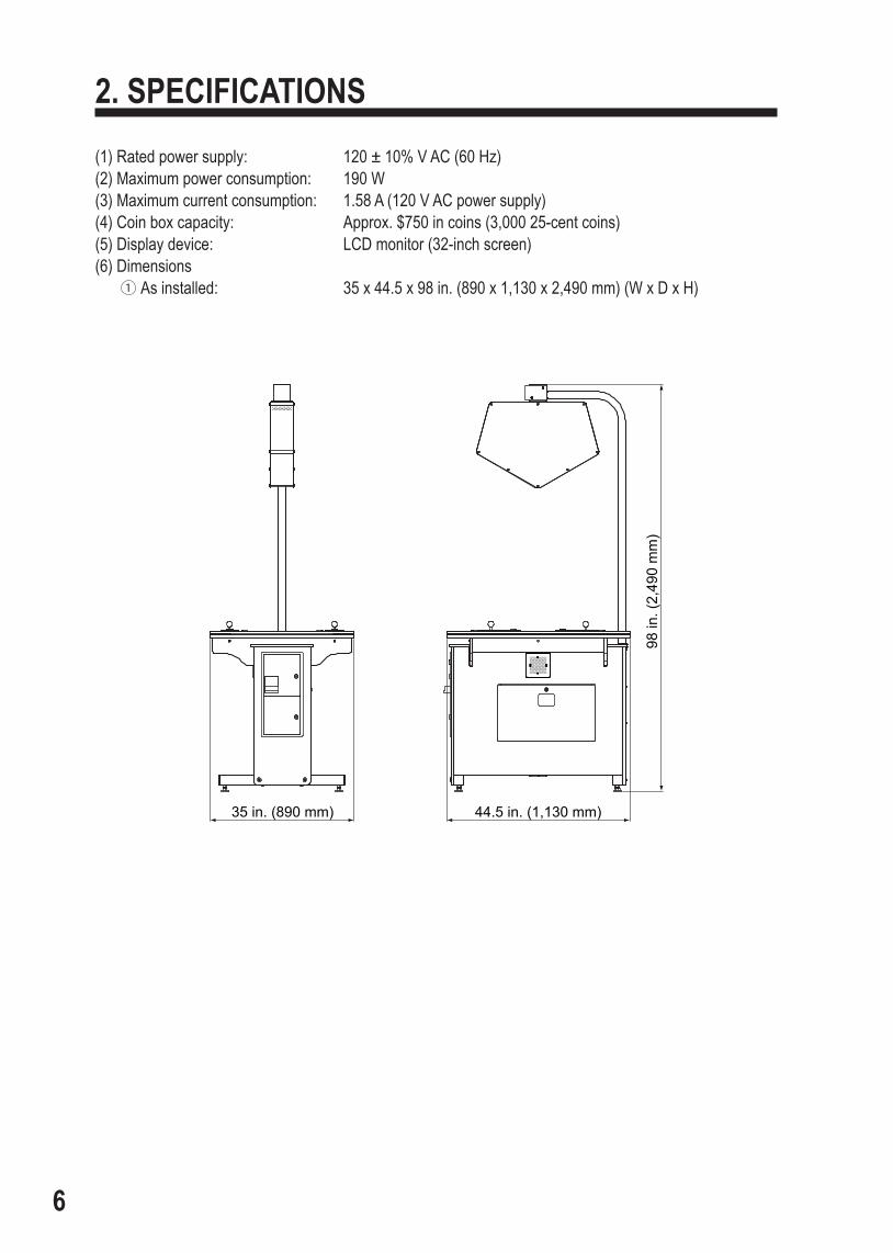
2. SPECIFICATIONS(1) Rated power supply: 120 ± 10% V AC (60 Hz)(2) Maximum power consumption: 190 W(3) Maximum current consumption: 1.58 A (120 V AC power supply)(4) Coin box capacity: Approx. $750 in coins (3,000 25-cent coins)(5) Display device: LCD monitor (32-inch screen)(6) Dimensions
1 As installed: 35 x 44.5 x 98 in. (890 x 1,130 x 2,490 mm) (W x D x H)
35 in. (890 mm) 44.5 in. (1,130 mm)
98 in
. (2,
490
mm
)

2. SPECIFICATIONS
SPECIFICATIONSTest m
odeTroubleshooting
7
2 When divided Cabinet: 35 x 44.5 x 38.6 in. (890 x 1,130 x 980 mm) (W x D x H)
35 in. (890 mm) 44.5 in. (1,130 mm)
38.6
in. (
980
mm
)
41 in
. (1,
040
mm
)
Signboard assembly: 5.1 x 33.1x 87 in. (130 x 840 x 2,210 mm) (W x D x H)
33.1 in. (840 mm)5.1 in. (130 mm)
87 in
. (2,
210
mm
)
(7) Weight1 As installed: Approx. 286.6 lb. (130 kg)2 When divided Cabinet: Approx. 242.5 lb. (110 kg) Signboard assembly: Approx. 35.3 lb. (16 kg)

8
3. PACKAGE CONTENTSThe product packages shipped from the factory contain the following components and parts.
Make sure that all the items listed below (except the service key) are contained in the coin box.
If any item is missing, contact your distributor.
Accessory listNo. Name Specification Qty.
1 Operation Manual Operation Manual 1
2 Service key 2
3 Coin box key 2
4 Power cord 1
5 Hex flange bolt M6 x 12 (For signboard) 4
6 Button head bolt M6 x 30 (For signboard pillar) 6
7 Flat washer M6 (For signboard pillar) 6

PACKAGE CONTENTS/OVERALL CONSTRUCTION (Names of Parts)
Test mode
Troubleshooting
9
4. OVERALL CONSTRUCTION (Names of Parts) Front
Signboard pillar
SignboardSignboard assembly
Fluorescent lamps(inside)
Control Panel assembly (3P, Blue)
Top Board assembly
Control Panel assembly(4P, Red)
Bill acceptor(option)
Under Box assembly Middle Box assembly
Side service door
Control Panel assembly(1P, Yellow)
Control Panel assembly(2P, Pink)
Front service door
Coin box door
Power switch
Fuse(5A 250V)
Cord box

10
5. INSTALLATION
WARNINGInstall the machine according to the instructions and procedures specified in this zzoperation manual. Failure to follow the specified procedures may result in a fire, electric shock, injury or machine malfunctions.Insert the power cord plug firmly into the AC outlet. Poor contact may cause zzoverheating that can lead to a fire or burns.Install the machine securely by using the level adjusters. Unstable machine zzinstallation can result in an accident or injury. (See P. 36 “8A-1-1 Securing the machine using level adjusters.”)
5-1 Installation conditions5-1-1 Locations to avoid when installing the machine
WARNINGThe machine is designed for indoor use. Never install the machine outdoors or in any zzof the following places:
A place subject to direct sunlight •A place exposed to rain or water leakage •Damp place •Dusty place •A place close to heating devices •Hot place •Extremely cold place •A place where dew condensation may occur due to temperature differences •A place where the machine may become an obstruction in emergencies (such as •near an emergency exit) or a place where a fire extinguisher or similar equipment is installedUnstable place or location where vibrations are produced •

5. INSTALLATION
Installation conditions/Required dimensions for bringing the m
achine insideTest m
odeTroubleshooting
11
5-1-2 Play zone for installed machine
WARNINGCreate a play zone around the machine (space as shown below) to prevent players zzcoming into contact with bystanders or passers-by.
z The distance from the floor to the ceiling must be at least 10.6 in. (2 m 70 cm).
3.5 in. (90 cm) or more
3.5 in.(90 cm) or more
Play zone
5-2 Required dimensions for bringing the machine inside (such as doors and corridors)
The machine is divided into separate components at the factory before shipping. The dimensions of main components are as follows:
As installed: z35 x 44.5 x 98 in. (890 x 1,130 x 2,490 mm) (W x D x H)Weight: Approx. 286.6 lb. (130 kg)
Without Signboard assembly: z35 x 44.5 x 38.6 in. (890 x 1,130 x 980 mm) (W x D x H)Weight: Approx. 242.5 lb. (110 kg)
Doors and corridors must be sufficiently higher and wider than the dimensions indicated above.Regarding the method of attaching the signboard assembly to the Under Box assembly, see “8A-1-3 (1) Attaching the signboard pillar.”

12
6. MOVING AND TRANSPORTING
WARNINGDo not leave the machine on a slope. If the machine is left on a slope, it may tip over zzand cause an accident.
6-1 Moving(onthefloor)
z Carefully transport the machine so as not to cause excessive impacts to it, as the LCD monitor is a precision electronic component.

6. MOVING AND TRANSPORTING
Test mode
TroubleshootingMoving(onthefloor)/Transportation
13
6-2 Transportation
6-2-1 Manualtransportation(carryingonstairs,etc.)
WARNINGThismachineweighsapproximately286.6lb.(130kg).zzWhen carrying the machine manually, be sure to remove the Signboard assembly zzfrom the machine, and raise all the level adjusters all the way (See P. 36 “8A-1 Assembly.”)Attempting tocarry themachinemanually (over stairs, etc.)withoutremoving the Signboard assembly as described above can result in an accident.If a corridor is narrow, separate the machine into parts. (See P. 11 “5-2 Required zzdimensionsforbringingthemachineinside(suchasdoorsandcorridors).”)When carrying the machine manually, the following number of people are needed. zzAttempting to carry the machine with fewer people can result in an accident or injury.
Machine without Signboard assembly: • (approx.286.6lb.(130kg)): 5peopleormoreSignboard assembly: • (approx.35.3lb.(16kg)): 1personormore
[When divided]Middle Box and Top Board assemblies: • (approx.110.2lb.(50kg)): 4peopleormoreUnder Box assembly: • (approx.132.3lb.(60kg)): 4peopleormore
z Do not drop the machine when lowering it. z Be sure to transport the machine with great care to avoid damaging it.

14
7. OPERATION
WARNINGSome monitor sections remain hot or charged with high voltage even after the power zzswitch is turned off. Do not touch the monitor unnecessarily in order to avoid electric shock and burns.Dust accumulated on the power cord plug may cause a fire. Check the power cord zzplug regularly and remove dust.Insert the power cord plug firmly into the AC outlet. Poor contact may cause zzoverheating that can lead to a fire or burns.Be sure to check that the machine has been installed according to the instructions zzand procedures specified in this operation manual (See P. 10 “5. INSTALLATION.”) before operating the machine. If the machine is not installed properly, fire, electric shock, injury or equipment malfunction can occur.The warning labels describe important safety precautions. Be sure to observe the zzfollowing:
To ensure that the warning labels attached to the machine are easily legible, •install the machine at an appropriate location with ample illumination and keep the labels clean at all times. Also, make sure that the labels are not hidden behind another game machine or other objects.Do not remove or alter the warning labels. •If the warning labels become excessively dirty or damaged, replace them with new •labels. To order warning labels, contact your distributor.
To ensure safe operation of the machine, be sure to conduct the pre-service check zz(see P. 15 “7-1 Pre-service check”) and Service (see P. 44 “8B. SERVICES”) described in this manual. Failure to conduct the pre-service check or service can result in an accident.
CAUTIONIf a player becomes sick due to light stimulation or game images, have that person zzstop playing the game immediately and let him/her rest.In rare cases, stimulation by lights or video images can cause convulsions or a loss zzof consciousness. If this happens, advise the player to consult a doctor as soon as possible. When pre-school children play, request their parents or guardians to keep an eye on the children.

7. OPERATION
Test mode
TroubleshootingPre-service check
15
7-1 Pre-service check
7-1-1 Safety check (before power ON)
WARNINGTo prevent accidents and injury, be sure to conduct the pre-service check described zzbelow before commencing operation.
(1) Are all warning indications in place? (See P. 3 “1-4 Description of warning labels attached to the machine.”)
(2) Are the warning indications legible? (See P. 3 “1-4 Description of warning labels attached to the machine.”)
(3) Are all level adjusters adjusted properly? (See P. 36 “8A-1-1 Securing the machine using level adjusters.”)
(4) Is the specified play zone provided? (See P. 11 “5-1-2 Play zone for installed machine.”)
(5) Is the power cord routed so that it will not cause players or other customers to trip over it?
(6) Is the power cord securely connected to the AC outlet and the power input socket on the machine?
(7) Is the power cord plug free of dust?(8) Is the signboard pillar securely attached to the Under Box assembly? (See P. 37
“8A-1-3 (1) Attaching the signboard pillar.”)(9) Is the signboard securely attached to the signboard pillar? (See P. 39 “8A-1-3 (2)
Attaching the signboard.”)(10) Is the under box side cover securely attached to the Under Box assembly? (See P.
37 “8A-1-3 (1) Attaching the signboard pillar.”)
Check the following items after turning on the power switch. If an abnormality is found, turn off the power switch immediately to stop operating the machine. Then, unplug the power cord from the AC outlet and contact your distributor.
(11) Is any part of the power cord or plug abnormally hot?(12) Does touching the machine give an electric shock?(13) Is there a burning smell, abnormal noise or vibration?(14) Is there any other sign of abnormality or malfunction?

16
7. OPERATION
7-1-2 Operation check (after power ON)
Check the following items in Test mode. (See P. 18 “7-2-2 Adjustment switches and but-tons.”)
(1) Check the lamps forproperoperation. (Do thefluorescentbulbandStartbuttonslight?)
(See P. 25 “7-4-4 Switch/sensor test (I/O TEST).”)(2) Check the Start buttons for proper operation. (See P. 25 “7-4-4 Switch/sensor test (I/O TEST).”)(3) Check the displayed image. (Does the monitor show images properly?) (See P. 28 “7-4-5 Monitor condition (MONITOR TEST).”)(4) Check the sound. (Is sound produced by each loudspeaker?) (See P. 29 “7-4-6 Sound adjustment (SOUND TEST).”)(5) Check the clock. (See P. 33 “7-4-8 (1) CLOCK SETTING.”)

7. OPERATION
Test mode
Troubleshooting
17
Pre-service check/Explanation of the power switch and adjustment switches
7-2 Explanation of the power switch and adjustment switches
7-2-1 Turning the power switch on
Power switch
z Be sure to complete the installation and setup of the machine before turning the power switch on.
z When turning the power switch on or off, wait at least 30 seconds between switch operations. Do not repeat turning the power switch on and off unnecessarily. Repeated on/off operations can cause damage to the data in the backup memory.

18
7. OPERATION
7-2-2 Adjustment switches and buttonsOpen the front service door to gain access to the adjustment switches and buttons.
Front service door
Test switch Select switch
Service button Enter button
Test switchSet this switch to ON to activate Test mode. Test mode is used to test the monitor and other parts. (See P. 21 “7-4 Test mode.”)
Service button (red)Press this button to increase the credit count without activating the coin counter.
Enter button (green)After selecting an item or setting (a numeric value) using the Select switch, press this button to enter or execute the selection.
Select switchInTestmode,flipthisswitchupordowntoselectanitemorsetting(anumericvalue).

19
7. OPERATION
Test mode
TroubleshootingExplanation of the power switch and adjustment switches/How to play the PAC-MAN BATTLE ROYALE
7-3 How to play PAC-MAN BATTLE ROYALE
7-3-1 Game rulesUp to four players can battle together. zIf your Pac-Man has eaten a power pellet, he can eat other players’ Pac-Men. zThe last one standing wins the round. zMultiple rounds can be played per battle royale. z
7-3-2 How to control your Pac-ManMove your Pac-Man through the maze by moving your joystick up, down, left, and right.
7-3-3 Items and a strategy in the mazePac-dotThe pac-dot pattern is refreshed when all pac-dots have been eaten.
FoodThe pac-dot pattern is refreshed when food is eaten, even if some pac-dots remain.
Power pelletWhen a Pac-Man eats a power pellet, he grows larger and other Pac-Men turn blue. The large Pac-Man can devour other blue Pac-Men.
TakeoutsWhen two equally-sized Pac-Men bump into each other, they bounce off of each other. To kill an opposing Pac-Man, bump your Pac-Man into it and knock it against a ghost.(Note that Pac-Men do not bump or pass through each other when they are blue.)
Food Pack-dotPower pellet
20
7. OPERATION
7-3-4 START buttonIf any credits remain when you press the START button, you can start playing the zgame.When you press the START button during a game in progress (group play), you (a zmaximumoffourplayers)canparticipateinthefirstavailableroundofplay.
(Notethatthisfunctionisnotavailableduringthefinalroundorinsinglemode.)When you (winner or loser) press the START button during intermission (while zWinner is displayed), you can throw paint bombs at the loser (for winner) or winner (for loser) to taunt your opponent(s).
(In solo play, the game proceed directly to the next round of play.)

21
7. OPERATION
Test mode
TroubleshootingHow to play the PAC-MAN BATTLE ROYALE/Test m
ode
7-4 Test mode
7-4-1 Description of the menu screen (MENU)
Unlock the front service door and set the Test switch to ON. (See P. 18 “7-2-2 Adjustment switches and buttons.”)The Menu screen appears on the monitor.
MENU
COIN OPTIONSGAME OPTIONSI/O TESTMONITOR TESTSOUND TESTBOOKKEEPINGOTHERS
CURRENT STATUSBALANCE $1.00SERVICE $0.00
SELECT SW:CHOOSE ENTER SW:ENTER
Game fee settings, etc.See section 7-4-2
Game detail settingsSee section 7-4-3
Switch/button/joystick testing, etc.See section 7-4-4
Monitor testingSee section 7-4-5
Sound adjustment, etc.See section 7-4-6
Bookkeeping checkSee section 7-4-7
Clock setting and backup memory initializationSee section 7-4-8
(a)(b)
Menu screen
Item Description(a) BALANCE Amount of money inserted before starting test mode.(b) SERVICE The amount for service games provided before starting test mode.
Flip the Select switch up or down to select an item. The selected item will blink. Press the Enter button to enter the selection. Applicable items under the selection
appear.
After all settings are complete, set the Test switch to OFF. The game display returns to the screen.

22
7. OPERATION
7-4-2 Game fee settings (COIN OPTIONS)
This screen is used to set the game fee, free play, and other options.
Select “COIN OPTIONS” in the Menu screen and press the Enter button. (See P. 21 “7-4-1 Description of the menu screen (MENU).”)The Coin Options screen appears on the monitor.
COIN OPTIONSDEFAULT IN GREEN
GAME COST $2.00FREE PLAY OFFPLAY TYPE GROUPCURRENCY DOLLARVALUE OF MECHANICAL COUNT $0.25VALUE OF COIN 1 $0.25VALUE OF COIN 2 $0.25VALUE OF COIN 3/BILL PULSE $0.25 EXIT
SELECT SW:CHOOSE ENTER SW:ENTER
(a)(b)(c)(d)(e)(f)
Coin Options screen
Item Description Factory settings
(a) GAME COST
Sets the game costA value range varies depending on the currency.DOLLAR: $ 0.25 to $ 25.0POUND: £ 0.10 to £ 10.0 £ 0.20 to £ 20.0 £ 0.50 to £ 50.0 £ 1 to £ 100 £ 2 to £ 200EURO: € 0.10 to € 10.0 € 0.20 to € 20.0 € 0.50 to € 50.0 € 1 to € 100 € 2 to € 200COIN: 1 to 100
$ 2.00
(b) FREE PLAY Turns Free Play on or offON/OFF OFF
(c) PLAY TYPESets the play type
GROUP: Up to four people can play during one play.SINGLE: A game fee required for each player.
GROUP
(d) CURRENCY Sets the currencyDOLLAR/POUND/EURO/COIN DOLLAR

23
7. OPERATION
Test mode
TroubleshootingTest m
ode
Item Description Factory settings
(e) VALUE OF MECHANICAL COUNT
Sets the incremental value of the coin counterThe value range varies depending on the currency.DOLLAR: $0.25(fixedvalue)POUND: £ 0.10/£ 0.20/£ 0.50/£ 1/£ 20EURO: € 0.10/€ 0.20/€ 0.50/€ 1/€ 20COIN: 1(fixedvalue)Each time the service button is pressed, the preset credit value increases in increments.
$ 0.25
(f) VALUE OF COIN 1(Settings for VALUE OF COIN 2 and VALUE OF COIN 3/BILL PULSE are the same.)
Sets the pulse input weighting for a coin selector or bill acceptor connected to COIN UNIT 1(As the input pulse value varies depending on the connected equipment, be sure to set the appropriate value.)The value range differs depending on the currency.DOLLAR: $ 0.25 to $ 25.0POUND: £ 0.10 to £ 10.0 £ 0.20 to £ 20.0 £ 0.50 to £ 50.0 £ 1 to £ 100 £ 2 to £ 200EURO: € 0.10 to € 10.0 € 0.20 to € 20.0 € 0.50 to € 50.0 € 1 to € 100 € 2 to € 200COIN: 1 to 100
$ 0.25
Flip the Select switch up or down to select an item. The selected item will blink. Press the Enter button to enter the selection. Flip the Select switch up or down to change the setting, and then press the Enter
button to enter the change. The display returns to the previous selection screen.
To return to the Menu screen, select “EXIT” and press the Enter button.

24
7. OPERATION
7-4-3 Game detail settings (GAME OPTIONS)
This screen is used to set the game details.
Select “GAME OPTIONS” in the Menu screen and press the Enter button. (See P. 21 “7-4-1 Description of the menu screen (MENU).”)The Game Options screen appears on the monitor.
GAME OPTIONSDEFAULT IN GREEN
GAME SPEED NORMALROUND NUMBERS 5TIME OUT NORMAL EXIT
SELECT SW:CHOOSE ENTER SW:ENTER
(a)(b)(c)
Game Options screen
Item Description Factory settings
(a) GAME SPEED Sets the game speedFAST/NORMAL/SLOW NORMAL
(b) ROUND NUMBERS Sets the available round number.3 to 9 5
(c) TIME OUT Sets the time-out duration for one round.LONG/NORMAL/SHORT NORMAL
Flip the Select switch up or down to select an item. The selected item will blink. Press the Enter button to enter the selection. Flip the Select switch up or down to change the setting, and then press the Enter
button to enter the change. The display returns to the previous selection screen.
To return to the Menu screen, select “EXIT” and press the Enter button.
25
7. OPERATION
Test mode
TroubleshootingTest m
ode
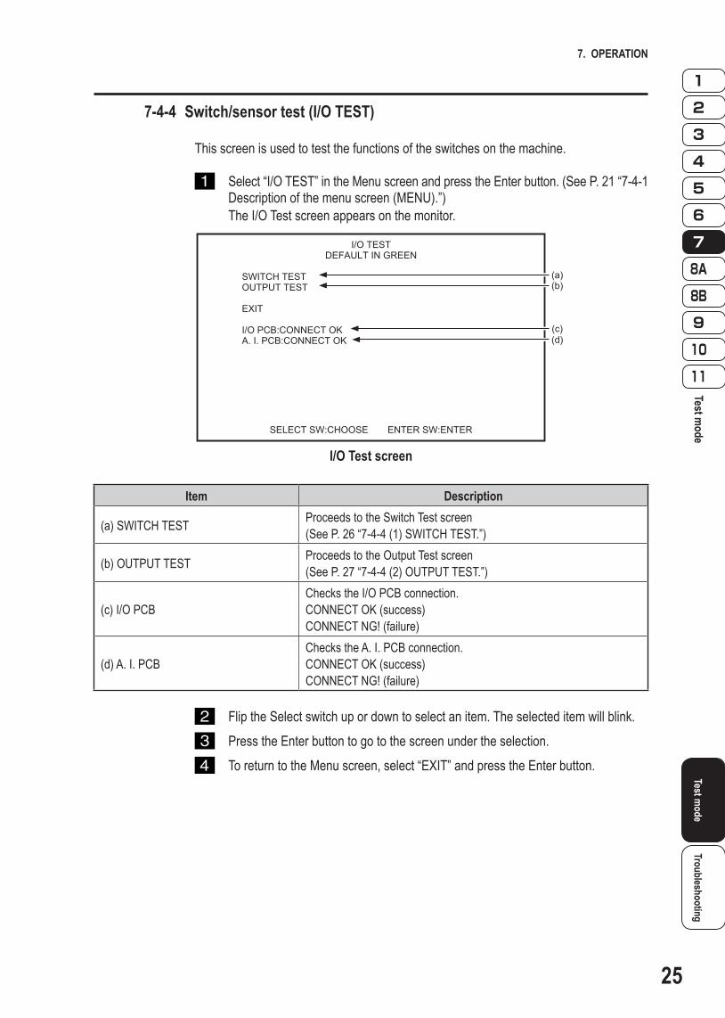
7-4-4 Switch/sensor test (I/O TEST)
This screen is used to test the functions of the switches on the machine.
Select “I/O TEST” in the Menu screen and press the Enter button. (See P. 21 “7-4-1 Description of the menu screen (MENU).”)The I/O Test screen appears on the monitor.
I/O TESTDEFAULT IN GREEN
SWITCH TESTOUTPUT TEST EXIT
I/O PCB:CONNECT OKA. I. PCB:CONNECT OK
SELECT SW:CHOOSE ENTER SW:ENTER
(a)(b)
(c)(d)
I/O Test screen
Item Description
(a) SWITCH TEST Proceeds to the Switch Test screen(See P. 26 “7-4-4 (1) SWITCH TEST.”)
(b) OUTPUT TEST Proceeds to the Output Test screen(See P. 27 “7-4-4 (2) OUTPUT TEST.”)
(c) I/O PCBChecks the I/O PCB connection.CONNECT OK (success)CONNECT NG! (failure)
(d) A. I. PCBChecks the A. I. PCB connection.CONNECT OK (success)CONNECT NG! (failure)
Flip the Select switch up or down to select an item. The selected item will blink. Press the Enter button to go to the screen under the selection. To return to the Menu screen, select “EXIT” and press the Enter button.
26
7. OPERATION
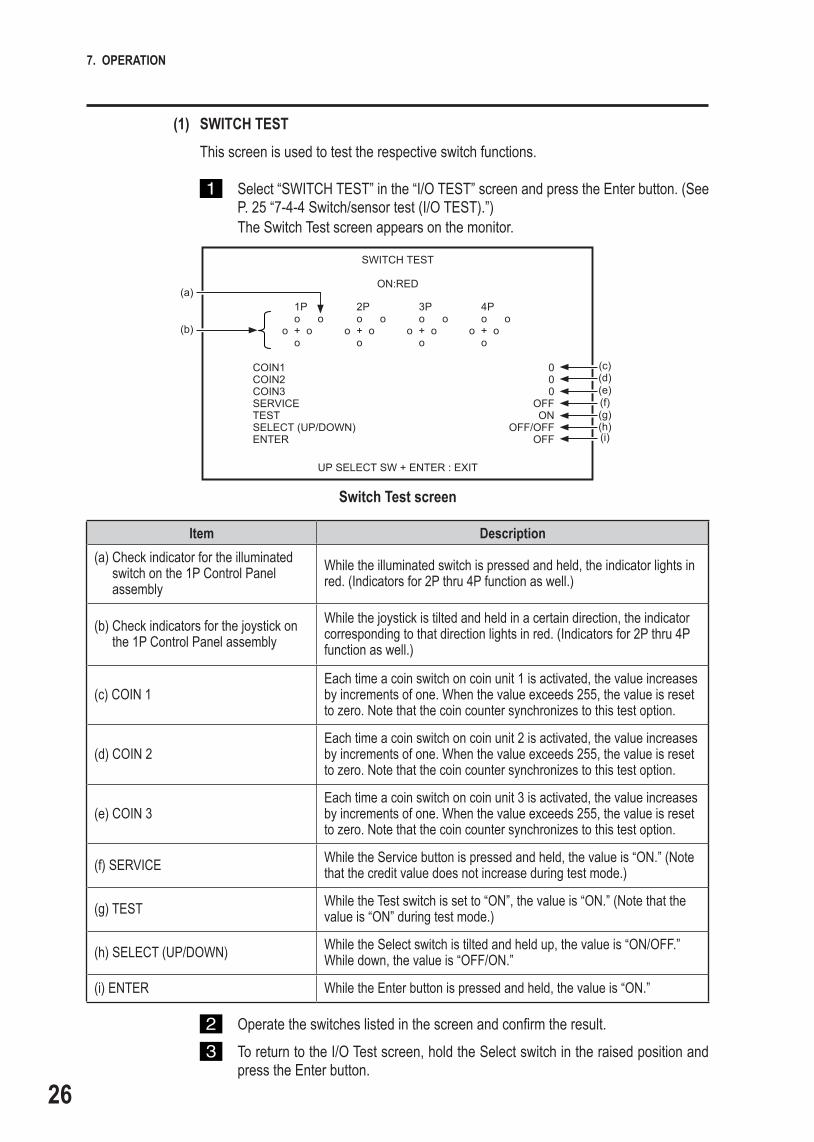
(1) SWITCH TESTThis screen is used to test the respective switch functions.
Select “SWITCH TEST” in the “I/O TEST” screen and press the Enter button. (See P. 25 “7-4-4 Switch/sensor test (I/O TEST).”)The Switch Test screen appears on the monitor.
SWITCH TEST
ON:RED
COIN1 0COIN2 0COIN3 0SERVICE OFFTEST ONSELECT (UP/DOWN) OFF/OFFENTER OFF
UP SELECT SW + ENTER : EXIT
(c)(d)(e)(f)(g)(h)(i)
1 P o oo + o o
(a)
(b)
2 P o oo + o o
3 P o oo + o o
4 P o oo + o o
Switch Test screen
Item Description(a) Check indicator for the illuminated
switch on the 1P Control Panel assembly
While the illuminated switch is pressed and held, the indicator lights in red. (Indicators for 2P thru 4P function as well.)
(b) Check indicators for the joystick on the 1P Control Panel assembly
While the joystick is tilted and held in a certain direction, the indicator corresponding to that direction lights in red. (Indicators for 2P thru 4P function as well.)
(c) COIN 1Each time a coin switch on coin unit 1 is activated, the value increases by increments of one. When the value exceeds 255, the value is reset to zero. Note that the coin counter synchronizes to this test option.
(d) COIN 2Each time a coin switch on coin unit 2 is activated, the value increases by increments of one. When the value exceeds 255, the value is reset to zero. Note that the coin counter synchronizes to this test option.
(e) COIN 3Each time a coin switch on coin unit 3 is activated, the value increases by increments of one. When the value exceeds 255, the value is reset to zero. Note that the coin counter synchronizes to this test option.
(f) SERVICE While the Service button is pressed and held, the value is “ON.” (Note that the credit value does not increase during test mode.)
(g) TEST While the Test switch is set to “ON”, the value is “ON.” (Note that the value is “ON” during test mode.)
(h) SELECT (UP/DOWN) While the Select switch is tilted and held up, the value is “ON/OFF.” While down, the value is “OFF/ON.”
(i) ENTER While the Enter button is pressed and held, the value is “ON.”
Operatetheswitcheslistedinthescreenandconfirmtheresult. To return to the I/O Test screen, hold the Select switch in the raised position and
press the Enter button.

27
7. OPERATION
Test mode
TroubleshootingTest m
ode
(2) OUTPUT TEST
This screen is used to test the illuminated switches.
Select “OUTPUT TEST” in the “I/O TEST” screen and press the Enter button. (See P. 25 “7-4-4 Switch/sensor test (I/O TEST).”)The Output Test screen appears on the monitor.
OUTPUT TEST
ON:RED
LAMP1 OFFLAMP2 OFFLAMP3 OFFLAMP4 OFF EXIT
SELECT SW:CHOOSE ENTER SW:ENTER
(a)(b)(c)(d)
Output Test screen
Item Description(a) LAMP1 When this item is set to “ON,” the 1P Start button lights.(b) LAMP2 When this item is set to “ON,” the 2P Start button lights.(c) LAMP3 When this item is set to “ON,” the 3P Start button lights.(d) LAMP4 When this item is set to “ON,” the 4P Start button lights.
Flip the Select switch up or down to select an item. The selected item will blink. Press the Enter button to enter the selection. Flip the Select switch to turn on the illuminated switch corresponding to the
selected item.
Before selecting the next item, press the Enter button. Repeat steps 2 thru 5 until all the switches have been checked.
To return to the I/O Test screen, select “EXIT” and press the Enter button.

28
7. OPERATION
7-4-5 Monitor condition test (MONITOR TEST)
This screen is used to check the monitor.
Select “MONITOR TEST” in the Menu screen and press the Enter button. (See P. 21 “7-4-1 Description of the menu screen (MENU).”)The Monitor Test screen appears on the monitor.
MONITOR TEST
GRADATION PATTERNCROSSHATCH PATTERNFULL WHITE EXIT
SELECT SW:CHOOSE ENTER SW:ENTER
(a)(b)(c)
Monitor Test screen
Item Description(a) GRADATION PATTERN Displays a 16-step gradation pattern.(b) CROSSHATCH PATTERN Displays a crosshatch pattern.(c) FULL WHITE Displays an all-white screen.
Flip the Select switch up or down to select an item. The selected item will blink. Press the Enter button to go to the screen under the selection. Press the Enter button again to return to the Monitor Test screen. To return to the Menu screen, select “EXIT” and press the Enter button.

29
7. OPERATION
Test mode
TroubleshootingTest m
ode
7-4-6 Sound adjustment (SOUND TEST)
This screen is used to adjust the sound volume, L/R channel balance, and other items.
Select “SOUND TEST” in the Menu screen and press the Enter button. (See P. 21 “7-4-1 Description of the menu screen (MENU).”)The Sound Test screen appears on the monitor.
SOUND TESTDEFAULT IN GREEN
VOLUME GAME (0~15) 10 ATTRACT (0~15) 10
REQUEST NO. 000LR CHECK EXIT
SELECT SW:CHOOSE ENTER SW:ENTER
SERVICE SW:REQUEST ON/OFF
(a)(b)
(c)(d)
(*)
Sound Test screen
Item Description Factory settings
(a) VOLUME GAME Sets the sound volume in Game mode.0 (no sound) to 15 (max.) 10
(b) VOLUME ATTRACT Sets the sound volume in Attract mode.0 (no sound) to 15 (max.) 10
(c) REQUEST NO. Sets the sound type for the service button000 (no sound) to 095 000
(d) LR CHECKChecks the loudspeakersThe check tone is heard from the loudspeakers in the following order; LEFT speaker (1P and 2P side), RIGHT speaker (3P and 4P side), LEFT + RIGHT (both) speakers.
* The sound set in the REQUEST NO. option is heard when the service button is pressed.Press the service button while the VOLUME ATTRACT option is selected to check the volume set in the VOLUME ATTRACT option.Press the service button while an option other than the VOLUME ATTRACT is selected to check the volume set in the VOLUME GAME option.
Flip the Select switch up or down to select an item. The selected item will blink. Press the Enter button to enter the selection. Flip the Select switch up or down to change the setting, and then press the Enter
button to enter the change. The display returns to the previous selection screen.
To return to the Menu screen, select “EXIT” and press the Enter button.

30
7. OPERATION
7-4-7 Game data display/initialization (BOOKKEEPING)
This screen is used to display various game data.
Select “BOOK KEEPING” in the Menu screen and press the Enter button. (See P. 21 “7-4-1 Description of the menu screen (MENU).”)The Bookkeeping screen appears on the monitor.
BOOKKEEPING 1/4
POWER ON TIME 0:13 ‘20TOTAL PLAY TIME 0:00 ‘10AVE. PLAY TIME 0:00 ‘00PLAY ON RATIO 0.0%PLAY COUNT 0COIN COUNT 0SERVICE SW COUNT 0
NEXTERROR LOGBOOKKEEPING INITIALIZE
EXIT
SELECT SW:CHOOSE ENTER SW:ENTER
(a)(b)(c)(d)(e)(f)(g)
(h)(i)(j)
Bookkeeping screen
Item Description(a) POWER ON TIME Shows the time when the machine is turned on(b) TOTAL PLAY TIME Shows the total playing time(c) AVE. PLAY TIME Shows the average playing time per play
(d) PLAY ON RATIO Shows the game-playing ratio (POWER ON TIME divided by TOTAL PLAY TIME)
(e) PLAY COUNT Shows the total number of plays(f) COIN COUNT Shows the total number of coins(g) SERVICE SW COUNT Shows the total number of time the service button is pressed(h) NEXT Goes to the next screen(i) ERROR LOG Shows the error log (See P. 31 “7-4-7 (1) ERROR LOG.”)
(j) BOOKKEEPING INITIALIZE
Initializes bookkeepingYES: Start initialization/NO: Stop initializationNote that the BACK UP MEMORY INITIALIZE option (See P. 32 “7-4-8 (2) Initialization and other settings (OTHERS).”) can also initialize bookkeeping.
Flip the Select switch up or down to select an item. The selected item will blink. To return to the Menu screen, select “EXIT” and press the Enter button.

31
7. OPERATION
Test mode
TroubleshootingTest m
ode
(1) ERROR LOG
This screen is used to check error logs.
Select “ERROR LOG” in the Bookkeeping screen and press the Enter button. (See P. 30 “7-4-7 Game data display/initialization (BOOKKEEPING).”)The Error Log screen appears on the monitor.
ERROR LOG 1/2
01 COIN ERROR1 JAN/01/2010 FRI 10:0902 COIN ERROR1 JAN/01/2010 FRI 10:0803 COIN ERROR1 JAN/01/2010 FRI 10:0704 COIN ERROR1 JAN/01/2010 FRI 10:0605 COIN ERROR1 JAN/01/2010 FRI 10:0506 COIN ERROR1 JAN/01/2010 FRI 10:0407 COIN ERROR1 JAN/01/2010 FRI 10:0308 COIN ERROR1 JAN/01/2010 FRI 10:0209 COIN ERROR1 JAN/01/2010 FRI 10:0110 COIN ERROR1 JAN/01/2010 FRI 10:00
NEXTEXIT
SELECT SW:CHOOSE ENTER SW:ENTER
Error Log screen
Flip the Select switch up or down to select an item. The selected item will blink. To proceed to the next page, select “NEXT” and press the Enter button (available
only when two or more pages exist).
To return to the Bookkeeping screen, select “EXIT” and press the Enter button.

32
7. OPERATION
7-4-8 Initialization and other settings (OTHERS)
This screen is used to initialize bookkeeping data (BOOKKEEPING) and other items.
Select “OTHERS” in the Menu screen and press the Enter button. (See P. 21 “7-4-1 Description of the menu screen (MENU).”)The Others screen appears on the monitor.
OTHERS
DATA PBR100-2-NA-MPRO-A57 MAY/26/2010 WED 20:40:54CLOCK JUN/23/2010 WED 14:06:24S/N 000000-000711
LANGUAGE ENGCLOCK SETTINGBACKUP MEMORY INITIALIZE
EXIT
SELECT SW:CHOOSE ENTER SW:ENTER
(a)
(b)(c)
(d)(e)(f)
Others screen
Item Description(a) DATA Shows the version information.(b) CLOCK Shows the date and time.(c) S/N Shows the serial number.
(d) LANGUAGE Shows the display language.ENG: English
(e) CLOCK SETTING Sets the built-in clock. (See P. 33 “7-4-8 (1) CLOCK SETTING.”)
(f) BACKUP MEMORY INITIALIZEInitializes the respective backup memory.(YES: Starts initialization/NO: Stops initialization)(See P. 34 “7-4-8 (2) BACKUP MEMORY INITIALIZE.”)
Flip the Select switch up or down to select an item. The selected item will blink. Press the Enter button to enter the selection. Flip the Select switch up or down to change the setting, and then press the Enter
button to enter the change. The display returns to the previous selection screen.
To return to the Bookkeeping screen, select “EXIT” and press the Enter button.

33
7. OPERATION
Test mode
TroubleshootingTest m
ode
(1) CLOCK SETTING
This screen is used to adjust the internal clock.
Select “CLOCK SETTING” in the Others screen and press the Enter button. (See P. 32 “7-4-8 Initialization and other settings (OTHERS).”)The Clock Setting screen appears on the monitor.
CLOCK SETTING
RECENTRY TIME: JAN/01/2010 FRI 10:00:00 CHANGE TO: JAN/01/2010 FRI 10:00
SET
EXIT
SELECT SW:CHOOSE ENTER SW:ENTER
(a)
(b)
(c)
Clock Setting screen
Item Description(a) RECENTRY TIME Shows the current time.(b) CHANGE TO: Sets the time.(c) SET Enters the change.
Flip the Select switch up or down to select an item. The selected item will blink. Press the Enter button to enter the selection. Flip the Select switch up or down to change the setting, and then press the Enter
button to enter the change. The display returns to the previous selection screen.
Flip the Select switch to select “SET” and press the ENTER button. The internal clock starts working.
To return to the Others screen, select “EXIT” and press the Enter button.

34
7. OPERATION
(2) BACKUP MEMORY INITIALIZE
This screen is used to initialize the backup memory.
Select “BACKUP MEMORY INITIALIZE” in the Others screen and press the Enter button. (See P. 32 “7-4-8 Initialization and other settings (OTHERS).”)The YES/NO option appears next to the selection.
Select the YES option to initialize the backup memory.When initialization is complete, “COMPLETE!” appears on the screen.
BACKUP MEMORY INITIALIZE? NO YES
BACKUP MEMORY INITIALIZE COMPLETE!
To return to the Others screen, select “EXIT” and press the Enter button.

35
7. OPERATION
Test mode
TroubleshootingTest m
ode/Error display (for the arcade operator)
7-5 Error display (for the arcade operator)
z The following shows items to be checked by the arcade operator. If an error other than the following is encountered, request a technician for service. (Technicians, see P. 48 “8B-3 Error display (for the technician).”)
Error code Error indication Cause Remedy
2-3 BACKUP MEMORY ERROR 1
Backup memory damageInitialize the backup memory. (See P. 34 “7-4-8 (2) BACKUP MEMORY INITIALIZE.”)
MAIN PCB failureRequest a technician for service. (See P. 48 “8B-3 Error display (for the technician).”)
2-4 BACKUP MEMORY ERROR 2
Backup memory damageInitialize the backup memory.(See P. 34 “7-4-8 (2) BACKUP MEMORY INITIALIZE.”)
MAIN PCB failureRequest a technician for service. (See P. 48 “8B-3 Error display (for the technician).”)

36
8A. ASSEMBLY AND SETUP – To be conducted by a technician only –
8A-1 Assembly
8A-1-1 Securing the machine using level adjusters
After installing the machine in a location as described in “5-1 Installation conditions” on page 10, be sure to make the machine level and stable using the four level adjusters.
Level adjuster
8A-1-2 Removing and attaching the side service door
Remove the two Torx bolts (M5 x 40), unlock the door using the provided service key, and remove the door.
Attach the door following the above steps in reverse.
Side service door
Torx bolt (M5 × 40)
Under Box assembly (right side)
Service key

8A. Assembly and setup – To be conducted by a technician only –
Test mode
TroubleshootingAssem
bly
37
8A-1-3 Attaching the Signboard assembly
WARNINGThe Signboard assembly weighs approximately 286.6 lb. (16 kg). It should be zzattached by two or more people in a large work area to prevent accidents.Since attachment of the Signboard assembly is performed above waist level, prepare zza step ladder or platform to stand on. Performing the task in an awkward position can result in injury or machine damage.
(1) Attaching the signboard pillar
Remove the two button head bolts (M4 x 20), and then remove the under box side cover.
Button head bolt (M4 x 20)
Under box side cover
Insert the signboard pillar into the opening on the Under Box assembly.
Signboard pillar
Harness connector

8A. Assembly and setup – To be conducted by a technician only –
38
Secure the signboard pillar using the six button head bolts (M6 x 30).
Button head bolt (M6 x 30)
Remove the side service door (See P. 36 “8A-1-2 Removing and attaching the side service door.”), and then connect the harness connecter and crimping terminal from the pillar.
Crimping terminal
Harness connector
Place the under box side cover on the Under Box assembly, and then secure it using the two button head bolts (M4 x 20) (see ).

8A. Assembly and setup – To be conducted by a technician only –
Test mode
TroubleshootingAssem
bly
39
(2) Attaching the signboard
Hang the notched signboard bracket hole on the pillar. Two installation orientations are available for the signboard.
Signboard
Securethesignboardbracketusingthefourflangebolts(M6x12).
Flange Bolt (M6 x 12)

8A. Assembly and setup – To be conducted by a technician only –
40
Connect the wiring harness connector that is pulled out from the signboard into the conncter that is pulled out from the signboard pillar.
Harness connectors
Signboard pillar
Signboard
Cap the signboard bracket cover on the bracket, and then secure it using four flangebolts(M6x12).
Flange Bolts (M6 x 12)
Signboard bracket cover

8A. Assembly and setup – To be conducted by a technician only –
Test mode
Troubleshooting
41
Assembly/Disassem
bly for passing through a narrow corridor
8A-2 Disassembly for passing through a narrow corridor
8A-2-1 Removing the Middle Box assembly from the Under Box assembly
WARNINGTo prevent electric shock, accident or injury and to prevent damage to the electrical zzcircuitry of the machine, be sure to turn the power switch off before performing the tasks described below.
CAUTIONThe Middle Box assembly including the top board weighs approximately 110.2 lb. zz(50 kg). It should be removed by three or more people in a large work area to prevent accidents.
Turn the power switch off and unplug the power cable. (See P. 17 “7-2-1 Turning the power switch on.”)
Remove the side service door. (See P. 36 “8A-1-2 Removing and attaching the side service door.”)
DisconnectthefiveharnessconnectorsandtheD-sub15pinterminal.
Harness connectors
Monitor adjustment PCB D-sub 15 pin terminal
Harness connectors

42
8A. Assembly and setup – To be conducted by a technician only –
Push the disconnected harnesses and cords into the Middle Box assembly from the openings in the Middle Box assembly.
Removethefourflangebolts(M8x35)andfourflatwashers(M8xø25).
Flange bolt (8M × 35)
Flat washer (M8 x Ø25)

43
8A. Assembly and setup – To be conducted by a technician only –
Test mode
TroubleshootingDisassem
bly for passing through a narrow corridor
Lift the Middle Box assembly to remove it from the Under Box assembly.
Attach the Middle Box assembly following the above steps in reverse.
44
8B. SERVICES – To be conducted by a technician only –
WARNINGTo prevent electric shock, accident or injury and to prevent damage to the electrical zzcircuitry of the machine, be sure to turn the power switch off before servicing the machine (including preventive measures against failure and repairs).
8B-1 Inspections and services
WARNINGThe machine should be inspected and serviced on a regular basis. Failing to do so zzmay result in accidents or damage to the machine.
8B-1-1 Inspection items
Check the following inspection items regularly.
(1) Level adjusterMake sure that the machine is stable on the floor. (See P. 36 “8A-1-1 Securing zthe machine using level adjusters.”)
(2) Power cord plugMake sure that the power cord is connected firmly to the cord box on the zmachine and the AC outlet.Be sure to keep the cord box free of dust and dirt. zCheck to see if there are any cracks in the power cord. If the power cord is zabnormal in any way, replace it with a new one.
(3) Bolts and nuts Check to be sure that the bolts and nuts used for the following parts are not loose.
If any of them are loose, tighten them firmly.For securing the signboard pillar, signboard, and under box side cover (See P. 37 z“8A-1-3 Attaching the Signboard assembly”)For other assemblies and parts z

45
8B. SERVICES – To be conducted by a technician only –
Test mode
TroubleshootingInspections and services/Troubleshooting
8B-2 Troubleshooting
WARNINGTo prevent electric shock, accident or injury and to prevent damage to the electrical zzcircuitry of the machine, be sure to turn the power switch off before conducting the tasks described bellow.If the problems encountered are not found in 8B-2-1 thru 8B-2-5 or if the problem zzpersists, immediately turn the power switch off to stop the operation of the machine, and contact your distributor. Operating the machine without fixing a problem can result in an accident.
z In the event a machine malfunctions, check to make sure that all connections are secure.
z If there is a problem in the MAIN, I/O, A.I., or AMP PCB, the faulty parts must be repaired by our company. Never use a tester to conduct a continuity test. The internal voltage of a tester can damage ICs.
z When sending parts for repair, pack them carefully. When sending the MAIN, I/O, A.I., or AMP PCB, wrap it completely in foam or bubble wrap and place it in a corrugated cardboard box to protect it from external impact.

46
8B. SERVICES – To be conducted by a technician only –
8B-2-1 General
Problem Main cause Remedy Page
The machine will not turn on.
The power cord is disconnected. Connect the cord securely to the AC outlet.
The fuse is blown. Replace the fuse.
The game will not start. (The attraction is not displayed.)
The connectors on the MAIN PCB are disconnected. Connect them securely. Page 55
MAIN PCB failure Replace the PCB. Page 55
The machine malfunctions or operation is unstable.
The power supply voltage is outside the range of 104 to 127 V AC
Disconnect large power consuming equipment (air conditioners, large rides, etc.) from the same power line, and ensure that the game machine receives the specified power supply voltage.
8B-2-2 Middle Box assembly
Problem Main cause Remedy Page
No images on the LCD monitor
The connectors to the LCD monitor are disconnected. Connect them securely. Page 54
LCD monitor failure Replace the LCD monitor. Page 52MAIN PCB failure Replace the PCB. Page 55
8B-2-3 Under Box assembly
Problem Main cause Remedy Page
No sound from the loudspeakers
The sound volume is set to the minimum. Turn the volume up. Page 29
The connectors to the loudspeakers are disconnected. Connect them securely.
AMP PCB failure Replace the PCB. Page 59MAIN PCB failure Replace the PCB. Page 55

47
8B. SERVICES – To be conducted by a technician only –
Test mode
TroubleshootingTroubleshooting
8B-2-4 Control Panel assembly
Problem Main cause Remedy Page
One of the joysticks does not operate properly.
The connector on the joystick is disconnected. Connect it securely. Page 62
Joystick failure Replace the joystick. Page 62A.I. PCB failure Replace the PCB. Page 58
There is no response from one of the illuminated switches.
The connector on the illuminated switch is disconnected. Connect it securely. Page 63
Illuminated switch failure Replace the switch. Page 63I/O PCB failure Replace the PCB. Page 57
One of the illuminated switches does not light up.
The connector on the illuminated switch is disconnected. Connect it securely. Page 63
The LED lamp is burnt out. Replace the lamp. Page 63I/O PCB failure Replace the PCB. Page 57
8B-2-5 Signboard assembly
Problem Main cause Remedy Page
The fluorescent bulb does not light up.
The power cord connector for the Signboard assembly is disconnected.
Connect it securely. Page 38 and 40
The fluorescent bulb is burned out. Replace the bulb. Page 64
Loose fluorescent bulb Screw the bulb in securely. Page 64

48
8B. SERVICES – To be conducted by a technician only –
8B-3 Error display (for the technician)
z If the error indication remains after the appropriate countermeasures have been taken, set the Test switch to ON and then to OFF to cancel the error indication.
Error code Error indication Cause Remedy Page
1-2 COIN ERROR 2Service button failure or some other problem near the button
Contact your distributor.
1-11 COIN ERROR 1(COIN UNIT 1)
COIN UNIT 1 failureReplace the coin selector or bill acceptor connected to COIN UNIT 1.
COIN UNIT 1 wiring harness failure Contact your distributor.
1-21 COIN ERROR 1(COIN UNIT 2)
COIN UNIT 2 failureReplace the coin selector or bill acceptor connected to COIN UNIT 2.
COIN UNIT 2 wiring harness failure Contact your distributor.
1-31 COIN ERROR 1(COIN UNIT 3)
COIN UNIT 3 failureReplace the coin selector or bill acceptor connected to COIN UNIT 3.
COIN UNIT 3 wiring harness failure Contact your distributor.
2-3 BACKUP MEMORY ERROR 1
Backup memory damage Initialize the backup memory. Page 34MAIN PCB failure Replace the MAIN PCB. Page 55
2-4 BACKUP MEMORY ERROR 2
Backup memory damage Initialize the backup memory. Page 34MAIN PCB failure Replace the MAIN PCB. Page 55
2-5 BATTERY ERROR The MAIN PCB backup battery is dead. Replace the battery. Page 56
3-1 I/O ERROR 1The connectors on the I/O PCB are disconnected. Connect them securely. Page 57
I/O PCB failure Replace the I/O PCB. Page 57
3-3 I/O ERROR 2
The connectors on the I/O PCB are disconnected. Connect them securely. Page 57
I/O PCB wiring harness failure Contact your distributor.
3-11 I/O ERROR 3The connectors on the A.I. PCB are disconnected. Connect them securely. Page 58
A.I. PCB failure Replace the A.I. PCB. Page 58
3-13 I/O ERROR 4
The connectors on the A.I. PCB are disconnected. Connect them securely. Page 58
A.I. PCB wiring harness failure Contact your distributor.

49
8B. SERVICES – To be conducted by a technician only –
Test mode
TroubleshootingError display (for the technician)/Assem
bly and disassembly of the m
achine
8B-4 Assembly and disassembly of the machine
8B-4-1 Top Board assembly
(1) Removing and attaching the Top Board assembly
WARNINGTo prevent electric shock, accident or injury and to prevent damage to the electrical zzcircuitry of the machine, be sure to turn the power switch off before performing the tasks described below.
CAUTIONThe Top Board assembly weighs approximately 44.1 lb. (20 kg). It should be removed zzby three or more people in a large work area to prevent accidents.
Turn the power switch off. (See P. 17 “7-2-1 Turning the power switch on.”) Remove the side service door. (See P. 36 “8A-1-2 Removing and attaching the
side service door.”)
Disconnect the four harness connectors.
Harness connectorsHarness connectors

50
8B. SERVICES – To be conducted by a technician only –
Remove the six button head bolts (M6 x 30) and their flat washers (M6 x ø13).
Button head bolt (M6 × 30)
Flat washer (M6 x Ø13)
Lift the Top Board assembly to remove it from the Middle Box assembly.
z Care must be taken so that the harness connectors are not caught in the Middle Box assembly holes when lifting the Top Board assembly.
Attach the Top Board assembly following the above steps in reverse.

51
8B. SERVICES – To be conducted by a technician only –
Test mode
TroubleshootingAssem
bly and disassembly of the m
achine
(2) Replacing the monitor glass
WARNINGTo prevent electric shock, accident or injury and to prevent damage to the electrical zzcircuitry of the machine, be sure to turn the power switch off before performing the tasks described below.
CAUTIONThe monitor glass should be removed by two or more people in a large work area to zzprevent accidents.
Remove the Top Board assembly. (See P. 49 “8B-4-1 (1) Removing and attaching the Top Board assembly.”)
z The following disassembly work requires sufficient space below the Top Board assembly. Before starting work, lay the Top Board assembly on two stable and solid boxes, etc., as illustrated below, and make sure that the Top Board assembly is level and stable.
Remove the four flange nuts (M4) and flat washers (M4 x Ø24) to remove the glass retainers.
Flat washer(M4 x Ø24)
Flange nut (M4)

52
8B. SERVICES – To be conducted by a technician only –
Remove the monitor glass and the glass retainers.
Attach the monitor glass following the above steps in the reverse order.
8B-4-2 Middle Box assembly
(1) Replacing the LCD monitor
WARNINGTo prevent electric shock, accident or injury and to prevent damage to the electrical zzcircuitry of the machine, be sure to turn the power switch off before performing the tasks described bellow.The LCD monitor may remain hot after turning the power switch off. Be sure to allow zzthe LCD monitor to cool down before starting the replacement procedure.
CAUTIONThe LCD monitor weighs approximately 26.5 lb. (12 kg). It should be removed by two zzor more people in a large work area to prevent accidents.
Remove the Top Board assembly. (See P. 49 “8B-4-1 (1) Removing and attaching the Top Board assembly.”)

53
8B. SERVICES – To be conducted by a technician only –
Test mode
TroubleshootingAssem
bly and disassembly of the m
achine
Disconnect the harness connector and D-sub 15 pin terminal.
D-sub 15 pin terminal
Harness connector
Remove the four flange bolts (M4 x 12).
Flange bolt (M4 × 12)

54
8B. SERVICES – To be conducted by a technician only –
Lift the LCD monitor to remove it from the Middle Box assembly.
Remove the RGB and power cables from the LCD monitor.
Power cableRGB cable
Attach the LCD monitor following the above steps in reverse.

55
8B. SERVICES – To be conducted by a technician only –
Test mode
TroubleshootingAssem
bly and disassembly of the m
achine
8B-4-3 Under Box assembly
(1) Replacing the MAIN PCB
WARNINGTo prevent electric shock, accident and injury and to prevent damage to the electrical zzcircuitry of the machine, be sure to turn the power switch off before performing the tasks described below.
z The PCB can be easily damaged by static electricity. If the PCB is handled by a person charged with static electricity, parts mounted on the PCB can be damaged. Before touching the PCB, be sure to remove static electricity from your body by touching a grounded metal object.
Turn the power switch off. (See P. 17 “7-2-1 Turning the power switch on.”) Remove the side service door. (See P. 36 “8A-1-2 Removing and attaching the
side service door.”)
Disconnect the two harness connectors, D-sub 15 pin terminal, and 3.5 MM plug.
Harness connectorsD-sub 15 pin terminal
3.5 MM plug
Phillips pan head screw (M3 x 8)
Remove the four Phillips pan head screws (M3 x 8) with flat and spring washers to remove the MAIN PCB.
Attach the MAIN PCB following the above steps in reverse.

56
8B. SERVICES – To be conducted by a technician only –
(2) Replacing the backup battery on the MAIN PCB
WARNINGTo prevent electric shock, accident and injury and to prevent damage to the electrical zzcircuitry of the machine, be sure to turn the power switch off before performing the tasks described below.
z The PCB can be easily damaged by static electricity. If the PCB is handled by a person charged with static electricity, parts mounted on the PCB can be damaged. Before touching the PCB, be sure to remove static electricity from your body by touching a grounded metal object.
Turn the power switch off. (See P. 17 “7-2-1 Turning the power switch on.”) Remove the MAIN PCB. (See P. 55 “8B-4-3 (1) Replacing the MAIN PCB.”) Place the MAIN PCB on a flat surface such as a desk. While gently pressing on the battery with your finger, insert a non-conductive
small stick into the notch on the battery holder, and then tilt the stick to remove the battery.* Use a CR2032 for the backup battery.
Notch on thebattery holderBackup battery
(CR2032) Positive (+) pole
Negative (-) pole
MAIN PCB
Non-conductive stick
Attach the battery following the above steps in reverse.
57
8B. SERVICES – To be conducted by a technician only –
Test mode
TroubleshootingAssem
bly and disassembly of the m
achine
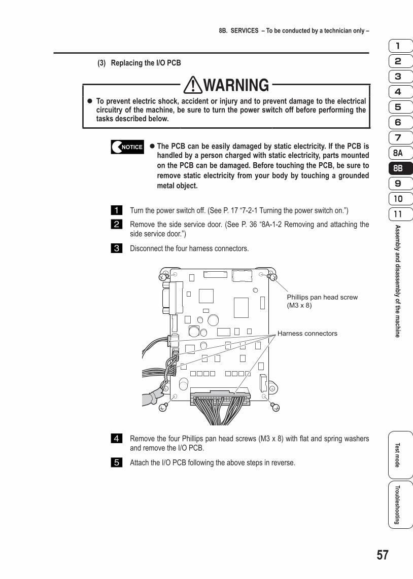
(3) Replacing the I/O PCB
WARNINGTo prevent electric shock, accident or injury and to prevent damage to the electrical zzcircuitry of the machine, be sure to turn the power switch off before performing the tasks described below.
z The PCB can be easily damaged by static electricity. If the PCB is handled by a person charged with static electricity, parts mounted on the PCB can be damaged. Before touching the PCB, be sure to remove static electricity from your body by touching a grounded metal object.
Turn the power switch off. (See P. 17 “7-2-1 Turning the power switch on.”) Remove the side service door. (See P. 36 “8A-1-2 Removing and attaching the
side service door.”)
Disconnect the four harness connectors.
Harness connectors
Phillips pan head screw(M3 x 8)
Remove the four Phillips pan head screws (M3 x 8) with flat and spring washers and remove the I/O PCB.
Attach the I/O PCB following the above steps in reverse.

58
8B. SERVICES – To be conducted by a technician only –
(4) Replacing the A.I. PCB
WARNINGTo prevent electric shock, accident or injury and to prevent damage to the electrical zzcircuitry of the machine, be sure to turn the power switch off before performing the tasks described below.
z The PCB can be easily damaged by static electricity. If the PCB is handled by a person charged with static electricity, parts mounted on the PCB can be damaged. Before touching the PCB, be sure to remove static electricity from your body by touching a grounded metal object.
Turn the power switch off. (See P. 17 “7-2-1 Turning the power switch on.”) Remove the side service door. (See P. 36 “8A-1-2 Removing and attaching the
side service door.”)
Disconnect the four harness connectors.
Harnessconnectors
Phillips pan head screw(M3 x 8)
Remove the four Phillips pan head screws (M3 x 8) with flat and spring washers and remove the A.I. PCB.
Attach the A.I. PCB following the above steps in reverse.

59
8B. SERVICES – To be conducted by a technician only –
Test mode
TroubleshootingAssem
bly and disassembly of the m
achine
(5) Replacing the AMP PCB
WARNINGTo prevent electric shock, accident or injury and to prevent damage to the electrical zzcircuitry of the machine, be sure to turn the power switch off before performing the tasks described below.
z The PCB can be easily damaged by static electricity. If the PCB is handled by a person charged with static electricity, parts mounted on the PCB can be damaged. Before touching the PCB, be sure to remove static electricity from your body by touching a grounded metal object.
Turn the power switch off. (See P. 17 “7-2-1 Turning the power switch on.”) Remove the side service door. (See P. 36 “8A-1-2 Removing and attaching the
side service door.”)
Disconnect the two harness connectors and RCA plug.
Harness connectors
RCA plug
Phillips pan head screws(M3 x 8)
Remove the three Phillips pan head screw (M3 x 8) with flat and spring washers and remove the AMP PCB.
Attach the AMP PCB following the above steps in reverse.

60
8B. SERVICES – To be conducted by a technician only –
(6) Replacing the power supply
WARNINGTo prevent electric shock, accident or injury and to prevent damage to the electrical zzcircuitry of the machine, be sure to turn the power switch off before performing the tasks described below.
z The PCB can be easily damaged by static electricity. If the PCB is handled by a person charged with static electricity, parts mounted on the PCB can be damaged. Before touching the PCB, be sure to remove static electricity from your body by touching a grounded metal object.
Turn the power switch off. (See P. 17 “7-2-1 Turning the power switch on.”) Remove the side service door. (See P. 36 “8A-1-2 Removing and attaching the
side service door.”)
Loose the Phillips pan head screws and remove the seven terminals.
Terminals
Phillips pan head screws(M3 x 8)
Phillips pan head screws
Remove the two Phillips pan head screws (M3 x 8) with flat and spring washers and remove the power supply.
Attach the power supply following the above steps in reverse.

61
8B. SERVICES – To be conducted by a technician only –
Test mode
TroubleshootingAssem
bly and disassembly of the m
achine
8B-4-4 Control Panel assembly
(1) Removing and attaching the Control Panel assembly
WARNINGTo prevent electric shock, accident and injury and to prevent damage to the electrical zzcircuitry of the machine, be sure to turn the power switch off before performing the tasks described below.
Remove the Top Board assembly. (See P. 19 “8B-4-1 (1) Removing and attaching the Top Board assembly.”)
Release the harness from the harness clamp on the back of the Top Board assembly.
Remove the six flanged nuts to remove the Control Panel assembly.
Harness clamp
Flanged nut
Attach the Control Panel assembly following the above steps in reverse.
z The Control Panel assemblies are color-coded for each player number. (See P. 9 “4 OVERALL CONSTRUCTION (Names of Parts).”) Make sure that all the Control Panel assemblies are attached in the correct positions.

62
8B. SERVICES – To be conducted by a technician only –
(2) Replacing the joystick
WARNINGTo prevent electric shock, accident and injury and to prevent damage to the electrical zzcircuitry of the machine, be sure to turn the power switch off before performing the tasks described below.
Remove the Top Board assembly. (See P. 49 “8B-4-1 (1) Removing and attaching the Top Board assembly.”)
While holding the thread on the bottom of the joystick shaft using a screwdriver, turn the joystick ball counterclockwise to remove the ball, collar, and upper Dustwasher.
Dustwashers
Joystick ball
Screwdriver
Collar
Remove the two flanged screws and disconnect the harness connector to remove the joystick.
Harness connector
Flanged screw
Attach the joystick following the above steps in reverse.

63
8B. SERVICES – To be conducted by a technician only –
Test mode
TroubleshootingAssem
bly and disassembly of the m
achine
(3) Replacing the illuminated switch and its LED lamp
WARNINGTo prevent electric shock, accident and injury and to prevent damage to the electrical zzcircuitry of the machine, be sure to turn the power switch off before performing the tasks described below.
Remove the Top Board assembly. (See P. 49 “8B-4-1 (1) Removing and attaching the Top Board assembly.”)
Remove the harness connector, and then turn the i l luminated switch counterclockwise to remove it.
Harness connector
Pull out the LED lamp from the illuminated switch.
LED lamp
Replace the illuminated switch or LED lamp. Attach the illuminated switch following the above steps in reverse, making sure
that the connector orientation is correct.

64
8B. SERVICES – To be conducted by a technician only –
8B-4-5 Signboard assembly
(1) Replacingthefluorescentlamp
WARNINGTo prevent electric shock, accident or injury and to prevent damage to the electrical zzcircuitry of the machine, be sure to turn the power switch off before performing the tasks described below.Since attachment of the Signboard assembly is performed above waist level, prepare zza step ladder or platform to stand on. Performing the task in an awkward position can result in injury or machine damage.Besuretoreplacewiththeproperfluorescentlamp.Don’tinstalltheothertypesofzzlamp.
Turn the power switch off. (See P. 17 “7-2-1 Turning the power switch on.”) Remove the eight Torx bolts (M5 x 8) and then the signboard panel.
Signboardpanel
Torx bolt(M5 x 8)
Replace the fluorescent lamp. Attach the signboard panel following the above steps in reverse.
Test mode
TroubleshootingAssem
bly and disassembly of the m
achine/DISPOSAL OF THE MACHINE
65
9. DISPOSAL OF THE MACHINE
WARNINGThe machine must be collected, transported and discarded in accordance with zzapplicable local laws and regulations.When entrusting a third party to collect, transport and discard the machine, be sure zzto select specialist companies.Dispose of used lithium batteries in accordance with local laws and regulations.zzBefore disposing of lithium batteries, place pieces of electrical insulation tape over zzboth the positive and negative electrodes. If the electrodes of the battery contact a metal object, a fire or explosion may result.

66
10. PARTS LISTS
10-1 Top Board assembly
513
8
439 6 12 1
2
10
11
7
No. Name Qty. Type and rating Part No.1 Top board 12 Monitor glass 1 PG99-13397-003 Glass retainer 4 PG10-13404-004 Corner sealing material 4 PG96-13425-005 Side sealing material A 2 PG96-13426-006 Side sealing material B 2 PG96-13427-007 Joint bracket 6 PG10-13403-008 Retainer guard A 8 PG96-13428-009 Retainer guard B 4
10 Money in sticker 1 PG40-13420-0011 Label, Caution Photosensitivity 212 Sealing Form A 213 Sealing Form B 2

10. PARTS LISTS
Test mode
Troubleshooting
67
Top Board assembly/Middle Box assem
bly
10-2 Middle Box assembly
2
3
1
No. Name Qty. Type and rating Part No.1 Middle box 12 Monitor bracket 2 PG10-13407-003 32" LCD Monitor 1 VG85-13741-00

10. PARTS LISTS
68
10-3 Under Box assembly
TEST SERVICE ENTER SELECT
22
8
13
7
12
9103421
24
2333 34 35 36
25
31 29 32
5
215
23
18
15
17
20
11
27
28
6
14
30
19
16
26

10. PARTS LISTS
Test mode
Troubleshooting
69
Under Box assembly
No. Name Qty. Type and rating Part No.1 Under box 12 Side service door 13 Service door lock 14 Seaker grill 25 Service panel 1 PG10-13412-006 Cord plate 1 VG10-09494-007 Under leg frame 2 PG10-13410-008 Under leg support 2 PG10-13402-009 Key washer 1
10 Coin lock 111 Level adjuster 412 Label, Warning Maintenance 1 VG44-12423-0013 Under box side cover 1 PG10-13416-0014 Signboard pillar support 1 PG10-13409-0015 PCB base 116 MAIN PCB 1 PG03-13391-0017 I/O PCB 1 PG03-13392-0018 A.I. PCB 1 PG03-13393-0019 AMP PCB 120 Power Supply 121 Speaker 2 VG54-12904-0022 Fan motor 123 Coin meter 1 VG83-13196-0024 Coin door Assy 1 VG83-13398-0025 Bill accepter (optional)26 Noise filter 1 VG78-12947-0027 Power switch 128 Fuse 1 5A 250V29 Push button 130 Push button 131 Flip switch 132 Flip switch 133 Label, Service panel "TEST" 1 VG44-02702-0034 Label, Service panel "SERVICE" 1 VG44-02702-0135 Label, Service panel "ENTER" 1 VG44-02702-1136 Label, Service panel "SELECT" 1 VG44-02702-07

10. PARTS LISTS
70
10-4 Control Panel assembly
1 2
10
6
14
( 3 for 2P)( 4 for 3P)( 5 for 4P)
( 11 for 2P)( 12 for 3P)( 13 for 4P)
( 7 for 2P)( 8 for 3P)( 9 for 4P)
No. Name Qty. Type and rating Part No.1 Control Panel 4 PG10-13411-002 Decal, Control Panel 1 1 YELLOW PG40-13421-003 Decal, Control Panel 2 1 PINK PG40-13421-014 Decal, Control Panel 3 1 LIGHT BLUE PG40-13421-025 Decal, Control Panel 4 1 RED PG40-13421-036 Decal, Button ST 1 1 YELLOW PG40-13422-007 Decal, Button ST 2 1 PINK PG40-13422-018 Decal, Button ST 3 1 LIGHT BLUE PG40-13422-029 Decal, Button ST 4 1 RED PG40-13422-03
10 Joystick 1 1 YELLOW VG80-11244-0011 Joystick 2 1 PINK VG80-11244-0012 Joystick 3 1 LIGHT BLUE VG80-11244-0013 Joystick 4 1 RED VG80-11244-0014 Illuminated switch 4 VG53-13399-00

10. PARTS LISTS
Test mode
Troubleshooting
71
Control Panel assembly/Signboard assem
bly
10-5 Signboard assembly
4
1
6
5 3 2
No. Name Qty. Type and rating Part No.1 Signboard frame 1 PG10-13414-002 Signboard pillar 1 PG10-13413-003 Signboard panel 2 PG95-13423-004 Signboard bracket 1 PG10-13401-005 Signboard bracket cover 1 PG10-13406-006 Fluorescent lamp 2

72
Test mode
TroubleshootingW
IRING DIAGRAMS
11. WIRING DIAGRAMS
Illuminated switch
LAMP1
1 1 GND
5 5 LEFT
2 2 DOWN3 3 UP4 4 RIGHT
Joystick JS1J28 NH5P
SW8
Illuminated switch
LAMP2
1 1 GND
5 5 LEFT
2 2 DOWN3 3 UP4 4 RIGHT
Joystick JS2J31 NH5P
SW9
Illuminated switch
LAMP3
1 1 GND
5 5 LEFT
2 2 DOWN3 3 UP4 4 RIGHT
Joystick JS3J34 NH5P
SW10
Illuminated switch
LAMP4
1 1 GND
5 5 LEFT
2 2 DOWN3 3 UP4 4 RIGHT
Joystick JS4J37 NH5P
SW11
AWG20
AW
G20
AW
G20
AW
G20
AWG20
AW
G20
AW
G20
AW
G20
1 1 Video
1 1 AC_IN
3 3 EARTH2 2 AC_RETGY
WH
11P1DOWN
99GND
22P1UP33P1RIGHT44P1LEFT55P2UP66P2DOWN77P2LEFT88P3RIGHT
J16 XAD20P
J17 XAD22P
1 1 +12V2 2 GND
OGBK
J15 VH2P
1 1 L+
3 3 GND2 2 L-
J14 XH3P
33P4SW
1919+12V
44P4LED55P3SW66P3LED77P2SW88P2LED99P1SW
1010P1LED
1 1 L+
3 3 GND2 2 L-
1 1 L+
3 3 GND2 2 L-
1 1 +12V
4 4 GND
2 2 +12V3 3 GND
J20 XH3P(RD)
J19 XH3P
J21 PA4POGOGBKBK
AB
J18 XAD40PJ18 XAD40P
BK
BNRDOGYE
BUVTGY
11P3UP
88P4LEFT
22P3DOWN33P3LEFT44P3RIGHT55P4DOWN66P4UP77P4RIGHT
1 1 +12V
4 4 GND
2 2 +12V3 3 GND
1 1 L+
3 3 GND2 2 L-
11Video
LR
GND
V387GAME PCB Assy
J22 XH3P
J24 PA4P
AWG20
AWG20
AWG20
AWG20
AWG20
AWG20
AWG20
AWG20
Control Panel Assy(P1)
Control Panel Assy(P2)
Control Panel Assy(P3)
Control Panel Assy(P4)
Control Panel FG1
Control Panel FG2
Control Panel FG3
Control Panel FG41 12 23 3
J2 YL3P
Top Board Assy
Middle Box Assy
Under Box Assy
FM
Cord box Cord box FG2Cord box FG1
112233
J1 VL3P
J43 YL3P
FLWHGY
J4
YL4
P
Signboard Assy
Signboard FG
3 cores cabtyre cable 0.75sq
AB
AB
AB
BK
1 12 23 34 45 56 67 78 89 9
Bill Validator
OG
BK
LT. BUBK
1 12 23 34 4
6 65 5
BK
COIN BOX
UP
DOWN
BKBK
BK
BK
J7 YL8P
SERVICE PANEL
Coin box FG
Service panel FG
1 12 23 34 45 56 67 78 8
J12
11+12V OGBK
OGBK
RDBU
YEVT
RDBU
YEVT
OGBK
J10 Molex156” 6P
J11 MATENLOK 4P
BKOG
BKOG
CC1 RD Accessory wireGY Accessory wire
OGVT
21
OGOGBKBK
BK
WHGY
BNRDYE
BUBK
J3
VL2
P
AWG16AWG16
AWG16AWG16
AWG16AWG16
WHGY
AWG16AWG16
J8 YL6P
J9 9P
J25 DSUB15P J26 DSUB15P
J23 Stereo 3.5ø
J27 YL9P
J30 YL9P
J33 YL9P
J36 YL9P
11
22
OG
BK
OG
BK J
39
YL2
P
1 12 23 34 45 56 67 78 89 9
1 12 23 34 45 56 67 78 89 9
1 12 23 34 45 56 67 78 89 9
1 12 23 34 45 56 67 78 89 9
Pillar FG
WHGY
J 42 YL3P
11
22
V387I/O PCB Assy
V343A.I.PCB Assy
11
22
33
44
COIN SWITCH2 SW6
COIN SWITCH 1 SW7
COIN METER
SwitchingRegurator
Fuse FU1 INLET3P
1P T
wis
t Pai
rC
able
0.3
SQ
1P T
wis
t Pai
r Cab
le 0
.3S
Q
Ste
reo3
.5 -
RC
A C
able
11
66
22SPL-
4455
SPR+
AC fan motor FM1
SP1SPEAKER1
4Ω 15W
SP2SPEAKER2
4Ω 15W
ANALOG VIDEO CABLE
3
123
40 40 GND
12 12 KANBAN LED
39 39 GND38 38 COIN CNT37 37 COIN SW335 35 COIN SW233 33 SERVICE SW31 31 COIN SW129 29 TEST SW27 27 ENTER SW25 25 UP SW23 23 DOWN SW20 20 +12V
FL1
AWG22AWG22
AWG22AWG22
AWG22
AWG22AWG22
AWG22AWG22
32inch LCDLCD1
112233
WH/VTWH/BUWH/GNWH/YEWH/OGWH/RDWH/BNWH/BKOG
WHPKLT. GNLT. BUWH/GY
WH/BKWH/BNGN/YE
GN
/YE
GN
/YE
GN
/YE
GN
/YE
GN
/YE
WH/BKWH/BNWH/RDWH/OGOGLT.BUWH/YEGN /YE
BKBKBNRDOGYEOG
WH/BKWH/BNGN/YE
WH/BKWH/BNWH/RDWH/OGOGLT.BUWH/YEGN /YE
BK
WH/BKWH/BNWH/RDWH/OGOGLT.BUWH/YEGN /YE
BK
WH/BKWH/BNWH/RDWH/OG
OGLT. BU
WH/YE
BK
BK
WH/BKWH/BNWH/RDWH/OG
OGLT. BU
WH/YE
BK
BK
WH/BKWH/BNWH/RDWH/OG
OGLT. BU
WH/YE
BK
BK
WH/BKWH/BNWH/RDWH/OG
OGLT. BU
WH/YE
BK
BK
GN/YE
GN/YE
GN/YE
GN/YE
GN/YE
GN/YE
GN/YE
BKBUGNGYVTOG
WH/RDWH/OG
BKPKWH
LT. BULT. GN
OGWH/YEWH/GN
OGBKBNRDOGYE
GN/YE
BUGNGYVT
WH/RDWH/OG
GN/YE
PKWHLT. BULT. GN
WH/YEWH/GN
GN/YE
WH/GYWH/PKWH/LT.GNWH/EL.BU
WH/BUWH/VT
GN/YEGYWH
GN/YEGYWH
GYWH
GN/YEGN/YEGYWH
GN
/YE
GY
WH
GN
/YE
GN
/YE
GN/YE
PKGY
GN / YE
GN
/YE
GN/
YEG
N/YE
GN/
YE
OGOGOG
OG
BKBKBKBK
WHGY
GN/YE
WH
GY
GN/
YE
WH
GY
GN
/YE
BNRDYEGNBUBKGN/YE
BNRDYEGNBUBK
GN/YE
BKVT
LT.BUWHRD
LT.GNBNBUYEGNOG
BKVTLT. BUWHRDLT. GNBNBUYEGNOG
GN/YE
OGBKLT. BUWHLT. GNGN/YE
OGBK
LT.BUWH
LT.GNGN/YE
BKBNRDOGYEGNBU
COLOR TABLEBLACKBROWNREDORANGEYELLOWGREENBLUE
VTGYWHPKLT. GNLT. BU
VIOLETGRAYWHITEPINKLIGHT GREENLIGHT BLUE
GN/YE
GN/YE
GND
GND
AC(L)AC(N)
FG
1 12 23 3
GN / YE
1 12 2
GN/YE
GN/YE
1 1 AC_IN
3 3 EARTH2 2 AC_RET
WHGY
WHGY
AWG16AWG16
GN
/YE
GN
/YE
FLWHGY
FL2
WHGY
14V White
14V White
14V White
14V White
Accessory wire
Test switch SW1
Service button SW2
Select switch SW3
Enter button SW4
REG1+12V12V 120W+12V
Powe
r cor
d
LINEFIL1 NOISE FILTER
INLET 3PPNE
LOAD
Power switch
SW5
GN/YE
GN/YE
J12
Stereo 3.5 - RCA Cable
OGOGBKBK
Stereo 3.5-RCA cable
“COLOR/COLOR” signed spiral cable
BKWH/GYWH/PK
WH/LT.GNWH/LT.BU
OGWH/BUWH/VTGN/YE
BKWH/BKWH/BNWH/RDWH/OGOGLT.BUWH/YEGN/YE
AWG20
AWG20
GN
GN / YEGN / YE
GN
WH/LT.GNWH/LT.BU
WH/PK
SPL+
SPR-
Gemini AMP PCB Assy
LR
GND
22GND
33SPS-SPS+
Note 1: If it is not mentioned, heavy green/yellow lines stand for AWG 16 wires, black heavy lines for AWG 18 wires, and black thin lines for AWG 24 wires in this diagram.
Note 2: If it is not mentioned, connectors in this diagram are Micro MATE-N-LOK Connectors.
Note 3: Pin contacts are used for cap connectors and socket contacts for plug connectors.