pa25342a01 ct-600-a rev. 01 5-2013 - panduit · © panduit corp. 2013 operating instructions...
TRANSCRIPT

CT-600-A
PA25342A01 Rev. 01 5-2013
PNEUMATIC CRIMPING TOOL OPERATING INSTRUCTIONS
HERRAMIENTA DE CRIMPEO NEUMÁTICO INSTRUCCIONES DE OPERACIÓN
© Panduit Corp. 2013
PNEUMATIC CRIMPING TOOL OPERATING INSTRUCTIONS (ENGLISH) ....................... 1 HERRAMIENTA DE CRIMPEO NEUMÁTICO INSTRUCCIONES DE OPERACIÓN (ESPAÑOL) .................................................................. 7
E-mail: [email protected]
www.panduit.com
Technical Support: 888-506-5400, ext. 83255
Correo electrónico Latino America: [email protected]
Si desea soporte técnico: Panduit Latino America,
Guadalajara, Jalisco, Mexico Latino America
Tel.: 52 (333) 666 2501 • Fax.: 52 (333) 666 2510
For Technical Support:
Si desea soporte técnico: www.panduit.com/resources/install_maintain.asp

CT-600-A
PA25342A01 Rev. 01 5-2013
PNEUMATIC CRIMPING TOOL OPERATING INSTRUCTIONS © Panduit Corp. 2013
TABLE OF CONTENTS
PRECAUTIONS AND GENERAL GUIDELINES .................................................................................. 1 CRIMPING HEADS ............................................................................................................................. 2 AIR SUPPLY ....................................................................................................................................... 3 OPERATING PRESSURE ................................................................................................................... 3 CRIMPING TOOL OPERATION .......................................................................................................... 3 MAINTENANCE................................................................................................................................... 3 INSTALLATION OF FOOT PEDAL CONTROL (FPC-600-A) ............................................................... 4 INSTALLATION OF POSITIONING DEVICE (PD-600-A) .................................................................... 5
Maintenance of Positioning Device ............................................................................................. 6 TROUBLESHOOTING ......................................................................................................................... 6
NOTE: In the interest of higher quality and value, Panduit products are continually being improved and updated. Consequently, pictures may vary from the enclosed product.

© Panduit Corp. 2013 OPERATING INSTRUCTIONS CT-600-A
Page: 1 of 12
PRECAUTIONS AND GENERAL GUIDELINES Always observe the following safety precautions when using this tool:
WARNING Read and understand all of the instructions and safety information in this manual before operating or servicing this tool. Failure to observe this warning can result in severe injury or death.
WARNING Electric Shock Hazard: • Verify electrical power is “OFF” before working on wiring with this tool. It is
not designed to insulate against shock and should never be used on live electric circuits.
• Do not use with frayed, abraded or cut air hose. Failure to observe this warning can result in severe injury or death.
WARNING • Do not remove the Safety Guard from the tip of the crimping head. It is
designed to guard against accidental closure on hands and is intended for the operator’s safety.
• Always lock the actuating lever in the neutral position when the tool is not in use. To lock the tool, move the Safety Lock to the “DOWN” position.
Failure to observe this warning can result in severe injury or death.
WARNING Wear eye protection when operating or servicing this tool. Failure to wear eye protection can result in serious eye injury from flying debris.
WARNING • Do not exceed air pressure of 115 psig.
© Panduit Corp. 2013 OPERATING INSTRUCTIONS CT-600-A
Page: 2 of 12
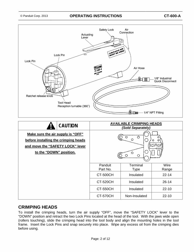
CAUTION AVAILABLE CRIMPING HEADS (Sold Separately)
Make sure the air supply is “OFF” before installing the crimping heads and move the “SAFETY LOCK” lever
to the “DOWN” position.
Panduit Part No.
Terminal Type
Wire Range
CT-500CH Insulated 22-14
CT-520CH Insulated 26-14
CT-550CH Insulated 22-10
CT-570CH Non-Insulated 22-10 CRIMPING HEADS To install the crimping heads, turn the air supply “OFF”, move the “SAFETY LOCK” lever to the “DOWN” position and retract the two Lock Pins located at the head of the tool. With the jaws wide open (rollers touching), slide the crimping head into the tool body and align the mounting holes in the tool frame. Insert the Lock Pins and snap securely into place. Wipe any excess oil from the crimping dies before using.

© Panduit Corp. 2013 OPERATING INSTRUCTIONS CT-600-A
Page: 3 of 12
AIR SUPPLY Connect the ¼” male air supply connector to a filter-regulator-lubricator unit rated at a minimum of 5 SCFM. Use a light weight oil compatible with Nitrile elastomer seals and the lubricator bowl materials.
NOTE: The tool has been designed to operate with lubricated air, therefore, a lubricator
must be used. Failure to use a lubricator will significantly shorten the tool life.
OPERATING PRESSURE For optimum air pressure setting, adjust the air supply regulator to 85 psig. Insert the desired terminal and wire into the proper size die and depress the actuating lever – the crimping head will close. The controlled cycle feature holds the crimp dies closed if the air pressure is too low. To open the crimp dies; turn the ratchet release knob next to the crimp head clockwise or counter-clockwise. Using new terminals and wires, increase the air pressure until the tool completes the crimp. Perform wire pullout test per customer’s test standards.
NOTE: Do not exceed the optimum air pressure setting, as this will cause premature tool wear.
CAUTION • READ SAFETY PRECAUTIONS ON PAGE 1 BEFORE USING THIS TOOL.
CRIMPING TOOL OPERATION
1. Move the “SAFETY LOCK” to the “DOWN” position to prevent accidental operation. 2. Rotate the Die Head to the proper orientation for the application. 3. Move the “SAFETY LOCK” to the “UP” position. 4. Set the optimum air pressure as instructed in the Operating Pressure Setting section above. 5. To crimp, insert the desired terminal and wire into the proper size die. Refer to the Product
Information Chart supplied with the crimping head or the product packaging for proper die selection and wire strip length.
6. Depress the actuating lever or foot petal and hold until the dies fully close. 7. Remove the terminal after the dies open.
MAINTENANCE Crimping Heads should be lubricated at least ONCE A WEEK. Lubricate all pins, pivots, rollers and bearing surfaces with a good grade SAE 20 motor oil. Be sure to clean any excess oil from the crimping dies before using the tool. For further information or assistance, call Panduit Tool Division at 888-506-5400, ext. 83255; and ask for one of our Tool Service Technicians. Contact Panduit Tool Division for repair or replacement.

© Panduit Corp. 2013 OPERATING INSTRUCTIONS CT-600-A
Page: 4 of 12
FOOT PEDAL CONTROL ASSEMBLY (FPC-600-A)
(Sold Separately)
INSTALLATION OF FOOT PETAL (FPC-600-A)
1. Position Actuator on back of CT-600-A and attach with thumbscrews. 2. Assemble ¼” NPT male connector from Air Hose to pipe tee connection. Connect ¼” Industrial
quick disconnect fittings to Air Supply Line. Refer to AIR SUPPLY section on Page 3.
¼” NPT connection for air line from CT-600-A
Front

© Panduit Corp. 2013 OPERATING INSTRUCTIONS CT-600-A
Page: 5 of 12
POSITIONING DEVICE (PD-600-A)
(Sold Separately)
INSTALLATION OF POSITIONING DEVICE (PD-600-A)
1. Clamp Positioning Device on edge of table. 2. Remove both screws holding the Tool Clamp Blocks 3. Install CT-600-A between Tool Clamp Blocks, away from CT-600-A’s Actuation Lever. 4. Tighten both Tool Clamp Block Screws. 5. Use Swivel Clamp Arm to loosen Positioning Device and position CT-600-A for operation.
BASE PLATE
HEXAGONAL SOCKET HEAD
SCREW (1) M10 x 16mm
POSITIONING CLAMP
SWIVEL CLAMP ARM
CLAMPING SCREW
TOOL CLAMP BLOCKS
HEXAGONAL SOCKET HEAD SCREW (2) M12 x 80mm

© Panduit Corp. 2013 OPERATING INSTRUCTIONS CT-600-A
Page: 6 of 12
MAINTENANCE OF POSITIONING DEVICE (PD-600-A) Adjusting Positioning Device Clamping
1. Release swivel clamp arm and lay CT-600-A tool on table surface. 2. Remove small screw above swivel clamp arm. 3. Rotate the plate above the swivel clamp arm clockwise 1/8 turn to the next threaded hole to
tighten. 4. Re-install small screw above swivel clamp arm. 5. Tighten 2 large screws opposite swivel clamp arm. 6. Position tool in desired orientation and tighten swivel clamp arm.
TROUBLESHOOTING
Problem Solution Dies stay closed at end of cycle a. Hold actuating lever or foot petal longer to allow the tool
to complete it’s cycle
b. Verify correct crimp pocket was used for the wire and terminal combination. Refer to product packaging or instructions included with the die
c. Verify the air pressure setting; increase if necessary

CT-600-A
PA25342A01 Rev. 01 5-2013
HERRAMIENTA DE CRIMPEO NEUMÁTICO INSTRUCCIONES DE OPERACIÓN
© Panduit Corp. 2013
CONTENIDO
PRECAUCIONES Y GUÍAS GENERALES ......................................................................................... 7 CABEZALES DE CRIMPEO ............................................................................................................... 8 SUMINISTRO DE AIRE ....................................................................................................................... 9 PRESIÓN DE OPERACIÓN ............................................................................................................... 9 OPERACIÓN DE LA HERRAMIENTA DE CRIMPEO .......................................................................... 9 MANTENIMIENTO .............................................................................................................................. 9 INSTALACIÓN DEL PEDAL DE CONTROL (FPC-600-A) ................................................................. 10 INSTALACIÓN DEL DISPOSITIVO DE POSICIONAMIENTO (PD-600-A) ........................................ 11
Mantenimiento del dispositivo de posicionamiento ................................................................... 12 DETECCIÓN DE PROBLEMAS ......................................................................................................... 12
NOTA: Por el interés de obtener una mayor calidad y valor, los productor de Panduit están siendo mejorados y actualizados continuamente. A consecuencia de esto, las imágenes pueden variar del producto adjunto.

© Panduit Corp. 2013 INSTRUCCIONES DE OPERACIÓN CT-600-A
Página: 7 of 12
PRECAUCIONES Y GUÍAS GENERALES Observe siempre las siguientes precauciones de seguridad al emplear esta herramienta:
ADVERTENCIA Lea y comprenda todas las instrucciones y la información sobre seguridad incluidas en este manual antes de operar o dar servicio a la herramienta. No observar esta advertencia puede provocar lesiones serias o incluso la muerte.
ADVERTENCIA
Peligro de choque eléctrico: • Verifique que la electricidad esté apagada (“OFF”) antes de trabajar con el
cableado de esta herramienta, la cual no ha sido diseñada para aislar un choque eléctrico y nunca deberá usarse con circuitos eléctricos activos.
• No emplee mangueras de aire que estén raídas, desgastadas o con cortes. No observar esta advertencia puede provocar lesiones serias o incluso la muerte.
ADVERTENCIA
• No retire el Dispositivo de Seguridad de la punta del cabezal del crimpeo, el cual ha sido diseñado para proteger las manos en caso de un cierre accidental. Su propósito es salvaguardar al operador.
• Asegure siempre la palanca de activación en la posición neutral cuando la herramienta no esté en uso. Para asegurar la herramienta lleve el Cierre de Seguridad hacia la posición “DOWN”.
No observar esta advertencia puede provocar lesiones serias o incluso la muerte.
ADVERTENCIA Use protección ocular al operar o dar servicio a la herramienta. No observar esta advertencia puede provocar lesiones serias o incluso la muerte.
ADVERTENCIA
• No exceda la presión de aire en más de 115 psig.

© Panduit Corp. 2013 INSTRUCCIONES DE OPERACIÓN CT-600-A
Página: 8 of 12
PRECAUCIÓN CABEZALES DE CRIMPEO DISPONIBLES (Se venden por separado)
Asegúrese de que el suministro de aire esté apagado (“OFF) antes de instalar
los cabezales de crimpeo; lleve la palanca del “CIERRE DE SEGURIDAD”
a la posición “DOWN”. No. de Parte
Panduit Tipo de Terminal Rango de Cable CT-500CH Con aislación 22-14
CT-520CH Con aislación 26-14
CT-550CH Con aislación 22-10
CT-570CH Sin aislacion 22-10
CABEZALES DE CRIMPEO Para instalar los cabezales de crimpeo, apague el suministro de aire (“OFF”); haga descender la palanca del “CIERRE DE SEGURIDAD” a la posición “DOWN” y retraiga los dos pins de seguridad, ubicados en el cabezal de la herramienta. Con las quijadas totalmente abiertas (los rodillos en contacto), deslice el cabezal del crimpeo en la herramienta y alinee las perforaciones de montaje en el marco de ésta. Inserte los pins de seguridad y presione para asegurarlos en su lugar. Limpie los dados de cualquier exceso de aceite antes de utilizarlos.

© Panduit Corp. 2013 INSTRUCCIONES DE OPERACIÓN CT-600-A
Página: 9 of 12
SUMINISTRO DE AIRE Inserte el conector macho de suministro de aire de ¼’’ a una unidad de filtro-regulador-lubricador con clasificación mínima de 5 SCFM. Utilice un aceite ligero compatible con los sellos de nitrilo de elastómero y con los materiales del recipiente lubricador.
NOTA: La herramienta ha sido diseñada para operar con aire lubricado, por lo tanto debe emplearse un lubricador.
El no utilizar lubricador acortará significativamente la vida de la herramienta.
PRESIÓN DE OPERACIÓN Para establecer de manera óptima la presión de aire, ajuste el regulador de suministro de aire en 85 psig. Inserte la terminal y cable deseados en el dado adecuado y oprima la palanca de activación – el cabezal de crimpeo se cerrará. Si la presión de aire es demasiado baja, el ciclo controlado en la herramienta hará que el dado de crimpeo se mantenga cerrado. Para abrir los dados de crimpeo, haga girar el botón de liberación con trinquete junto al cabezal de crimpeo, en el sentido o contra el sentido de las manecillas del reloj. Al usar terminales y cables nuevos, incremente la presión de aire hasta que el crimpeo se complete. Realice la prueba de arrastre del cable conforme los estándares de prueba del cliente.
NOTA: No sobrepase el ajuste óptimo de presión de aire pues eso ocasionara el desgaste prematuro de la herramienta.
PRECAUCIÓN
• LEA LAS PRECAUCIONES DE SEGURIDAD EN LA PÁGINA 7 ANTES DE USAR ESTA HERRAMIENTA
OPERACIÓN DE LA HERRAMIENTA DE CRIMPEO
1. Lleve el “CIERRE DE SEGURIDAD” a la posición “DOWN” para evitar la activación accidental. 2. Rote el cabezal del dado conforme la orientación adecuada para su aplicación. 3. Lleve el “CIERRE DE SEGURIDAD” a la posición “UP”. 4. Ajuste la presión óptima de aire según las instrucciones de presión de operación de la sección
anterior. 5. Para crimpear, inserte la terminal y el cable deseados en el dado del tamaño adecuado.
Consulte la Gráfica de Información de Productos que viene con el cabezal de crimpeo o en el paquete del producto para seleccionar el dado adecuado y la longitud de desforre del cable.
6. Oprima la palanca de activación o pedal y sosténgalo hasta que el dado cierre totalmente. 7. Retire la terminal después de que el dado se abra.
MANTENIMIENTO Deberán lubricarse los cabezales de crimpeo por lo menos UNA VEZ A LA SEMANA. Lubrique todos los pins, pivotes, rodillos y superficies de soporte con un buen aceite de motor grado SAE 20. Asegúrese de limpiar todo exceso de aceite de los dados de crimpeo antes de emplear la herramienta. Para mayor información o asistencia, llame a la División de Herramientas de Panduit, al 888-506-5400, ext. 83255; y pregunte por alguno de nuestros Técnicos de Servicio de Herramientas. Contacte con la División de Herramientas Panduit para reparaciones o reemplazos.

© Panduit Corp. 2013 INSTRUCCIONES DE OPERACIÓN CT-600-A
Página: 10 of 12
ENSAMBLE DEL CONTROL DE PEDAL (FPC-600-A)
(Se vende por separado)
INSTALACIÓN DEL PEDAL DE CONTROL (FPC-600-A)
1. Coloque el activador en el soporte de la CT-600-A y fíjelo con tornillos tipo mariposa. 2. Ensamble el conector macho NPT de ¼’’ desde la Manguera de Aire hacia la conexión del tubo
tipo “T”. Conecte los aditamentos de desconecte rápido industrial de ¼’’ a la línea de Suministro de Aire. Consulte la sección de SUMINISTRO DE AIRE en la página 9.
Conexión NPT ¼” para la línea de aire de la CT-600-A
Frente

© Panduit Corp. 2013 INSTRUCCIONES DE OPERACIÓN CT-600-A
Página: 11 of 12
DISPOSITIVO DE POSICIONAMIENTO (PD-600-A)
(Se vende por separado)
INSTALACIÓN DEL DISPOSITIVO DE POSICIONAMIENTO (PD-600-A)
1. Aseguree el dispositivo de posicionamiento a la orilla de una mesa. 2. Retire los dos tornillos que sostienen los Bloques de Sujeción de la Herramienta. 3. Instale la CT-600-A entre los Bloques de Sujeción de la Herramienta, de modo que la palanca de
activación quede alejada de la CT-600-A. 4. Ajuste los dos tornillos del Bloque de Sujeción de la Herramienta 5. Utilice el brazo giratorio de sujeción para aflojar el Dispositivo de Posicionamiento y coloque la
CT-600-A para su operación.
BASE
TORNILLO CABEZA HEXAGONAL (1)
M10 x 16mm
SUJETADOR DE POSICIONAMIENTO
BRAZO GIRATORIO DE SUJECIÓN
TORNILLO DE SUJECIÓN
TORNILLO CABEZA HEXAGONAL (2) M12 x 80mm
BLOQUES DE SUJECIÓN DE LA
HERRAMIENTA

© Panduit Corp. 2013 INSTRUCCIONES DE OPERACIÓN CT-600-A
Página: 12 of 12
MANTENIMIENTO DEL DISPOSITIVO DE POSICIONAMIENTO (PD-600-A) Ajuste de la sujeción del dispositivo de posicionamiento
1. Suelte el brazo giratorio de sujeción y coloque la herramienta CT-600-A en una superficie plana. 2. Retire el tornillo pequeño que se ubica sobre el brazo giratorio de sujeción. 3. Haga rotar la base sobre el brazo giratorio en el sentido del reloj en 1/8 de giro, hasta el
siguiente orificio en rosca para ajustar. 4. Coloque el tornillo pequeño de nuevo en su lugar, sobre el brazo giratorio de sujeción. 5. Ajuste los dos tornillos grandes opuestos al brazo de sujeción. 6. Coloque la herramienta en la orientación deseada y ajuste el brazo giratorio de sujeción.
DETECCIÓN DE PROBLEMAS
Problema Solución Los dados permanecen cerrados al final del ciclo
a. Sostenga la palanca de activación o el pedal por más tiempo para permitir que la herramienta complete su ciclo.
b. Verifique haber utilizado el pocket de crimpeo correcto para esa combinación de cable y terminal. Consulte la caja del producto o las instrucciones incluidas junto con el dado.
c. Verifique el ajuste de presión de aire; auméntelo si es necesario.