owner’s manual - water softener & water filter systems ... · owner’s manual chlorine...
TRANSCRIPT
Owner’s ManualChlorine Injection System with
Retention Tank
Rev I —Chlorine Injection System with Retention Tank
© 2012 Enviro Water Solutions, Inc.3060 Performance Circle, Suite 2, DeLand, FL 32724
Page 2
www.pelicanwater.com(877) 842-1635
© Copyright 2012 Enviro Water Solutions Inc. All rights reserved.
All information contained herein is the property of Pelican Water Systems. Pelican Water Systems makes no warranty of any kind with regard to this material, including, but not limited to, the implied warranties of merchantability and fitness for a particular purpose. Pelican Water Systems shall not be liable for technical or editorial errors or omissions contained herein or for incidental or consequential damages in connection with the furnishing, performance, or use of this material. The information is provided “as is” without warranty of any kind and is subject to change without notice. This document contains proprietary information which is protected by copyright. No part of this document may be photocopied, reproduced, or translated into another language without the prior written consent of Pelican Water Systems. Pelican Water Systems is an Enviro Water Solutions, Inc. company.
Rev I —Chlorine Injection System with Retention Tank
© 2012 Enviro Water Solutions, Inc.3060 Performance Circle, Suite 2, DeLand, FL 32724
Page 3
www.pelicanwater.com(877) 842-1635
Table of ContentsTable of Contents . . . . . . . . . . . . . . . . . . . . . . . . . . . . . . . . . . . . . . . . . . . . . . . . . . . . . . 3
Product Operation and Specifications . . . . . . . . . . . . . . . . . . . . . . . . . . . . . . . . . . . . . 4
Important Information . . . . . . . . . . . . . . . . . . . . . . . . . . . . . . . . . . . . . . . . . . . . . . . . . 4
Complete Parts List . . . . . . . . . . . . . . . . . . . . . . . . . . . . . . . . . . . . . . . . . . . . . . . . . . . . 5
Installation Overview . . . . . . . . . . . . . . . . . . . . . . . . . . . . . . . . . . . . . . . . . . . . . . . . . . 6
Installation . . . . . . . . . . . . . . . . . . . . . . . . . . . . . . . . . . . . . . . . . . . . . . . . . . . . . . . . . . . 7Chemical Injector Pump Installation . . . . . . . . . . . . . . . . . . . . . . . . . . . . . . . . . . . . . . 7Solution Tank Installation . . . . . . . . . . . . . . . . . . . . . . . . . . . . . . . . . . . . . . . . . . . . . 7Retention Tank Installation . . . . . . . . . . . . . . . . . . . . . . . . . . . . . . . . . . . . . . . . . . . 8
Complete the Installation . . . . . . . . . . . . . . . . . . . . . . . . . . . . . . . . . . . . . . . . . . . . . . . 9Testing Chlorine Levels in Water . . . . . . . . . . . . . . . . . . . . . . . . . . . . . . . . . . . . . . . . . . 9
Maintenance . . . . . . . . . . . . . . . . . . . . . . . . . . . . . . . . . . . . . . . . . . . . . . . . . . . . . . . . 10Solution Tank Refill . . . . . . . . . . . . . . . . . . . . . . . . . . . . . . . . . . . . . . . . . . . . . . . . 10Chemical Injector Pump: . . . . . . . . . . . . . . . . . . . . . . . . . . . . . . . . . . . . . . . . . . . . . . . 10
Troubleshooting . . . . . . . . . . . . . . . . . . . . . . . . . . . . . . . . . . . . . . . . . . . . . . . . . . . . . . 11
Warranty . . . . . . . . . . . . . . . . . . . . . . . . . . . . . . . . . . . . . . . . . . . . . . . . . . . . . . . . . . . 12Warranty Registration Form . . . . . . . . . . . . . . . . . . . . . . . . . . . . . . . . . . . . . . . . . . . . . 13
Rev I —Chlorine Injection System with Retention Tank
© 2012 Enviro Water Solutions, Inc.3060 Performance Circle, Suite 2, DeLand, FL 32724
Page 4
www.pelicanwater.com(877) 842-1635
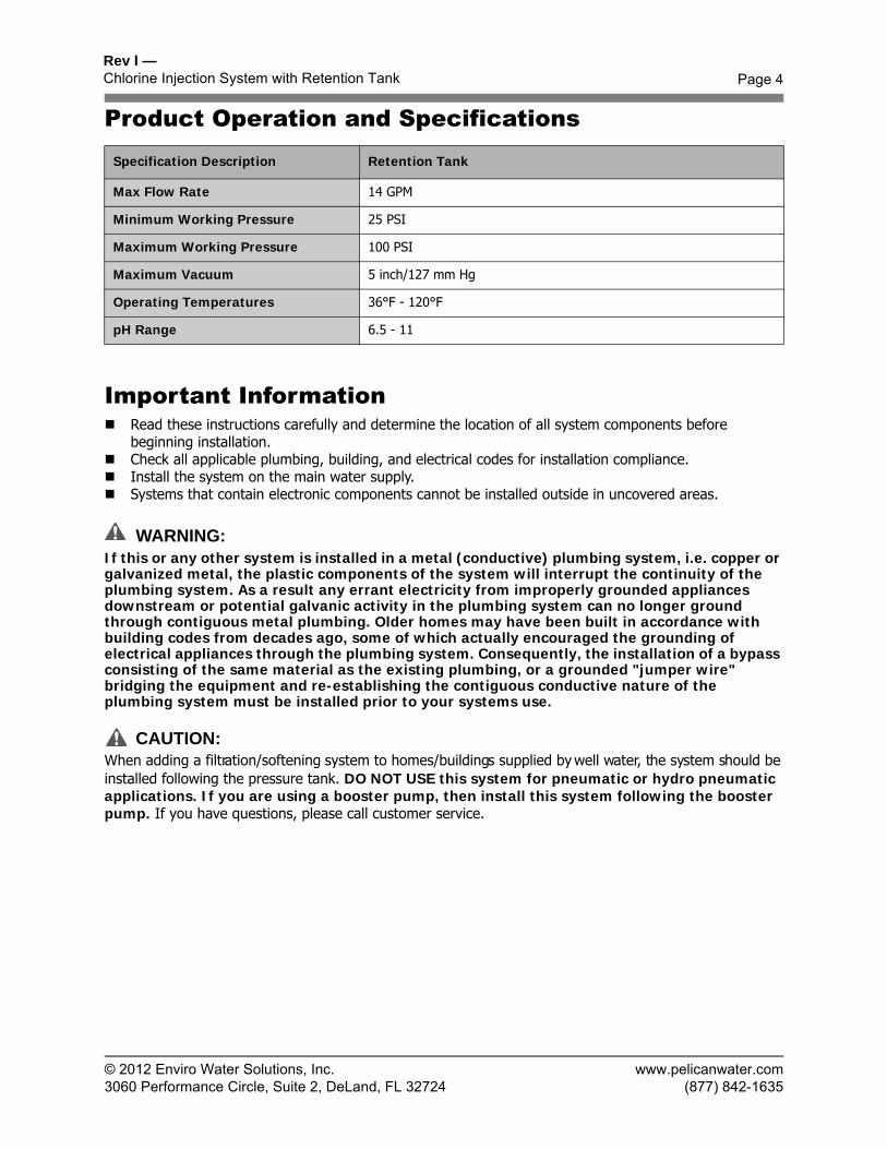
Product Operation and Specifications
Important Information Read these instructions carefully and determine the location of all system components before
beginning installation. Check all applicable plumbing, building, and electrical codes for installation compliance. Install the system on the main water supply. Systems that contain electronic components cannot be installed outside in uncovered areas.
WARNING:If this or any other system is installed in a metal (conductive) plumbing system, i.e. copper or galvanized metal, the plastic components of the system will interrupt the continuity of the plumbing system. As a result any errant electricity from improperly grounded appliances downstream or potential galvanic activity in the plumbing system can no longer ground through contiguous metal plumbing. Older homes may have been built in accordance with building codes from decades ago, some of which actually encouraged the grounding of electrical appliances through the plumbing system. Consequently, the installation of a bypass consisting of the same material as the existing plumbing, or a grounded "jumper wire" bridging the equipment and re-establishing the contiguous conductive nature of the plumbing system must be installed prior to your systems use.
CAUTION:When adding a filtration/softening system to homes/buildings supplied by well water, the system should be installed following the pressure tank. DO NOT USE this system for pneumatic or hydro pneumatic applications. If you are using a booster pump, then install this system following the booster pump. If you have questions, please call customer service.
Specification Description Retention Tank
Max Flow Rate 14 GPM
Minimum Working Pressure 25 PSI
Maximum Working Pressure 100 PSI
Maximum Vacuum 5 inch/127 mm Hg
Operating Temperatures 36°F - 120°F
pH Range 6.5 - 11
© 2012 Enviro Water Solutions, Inc.3060 Performance Circle, Suite 2, DeLand, FL 32724
Page 5
www.pelicanwater.com(877) 842-1635
Rev I —Chlorine Injection System with Retention Tank
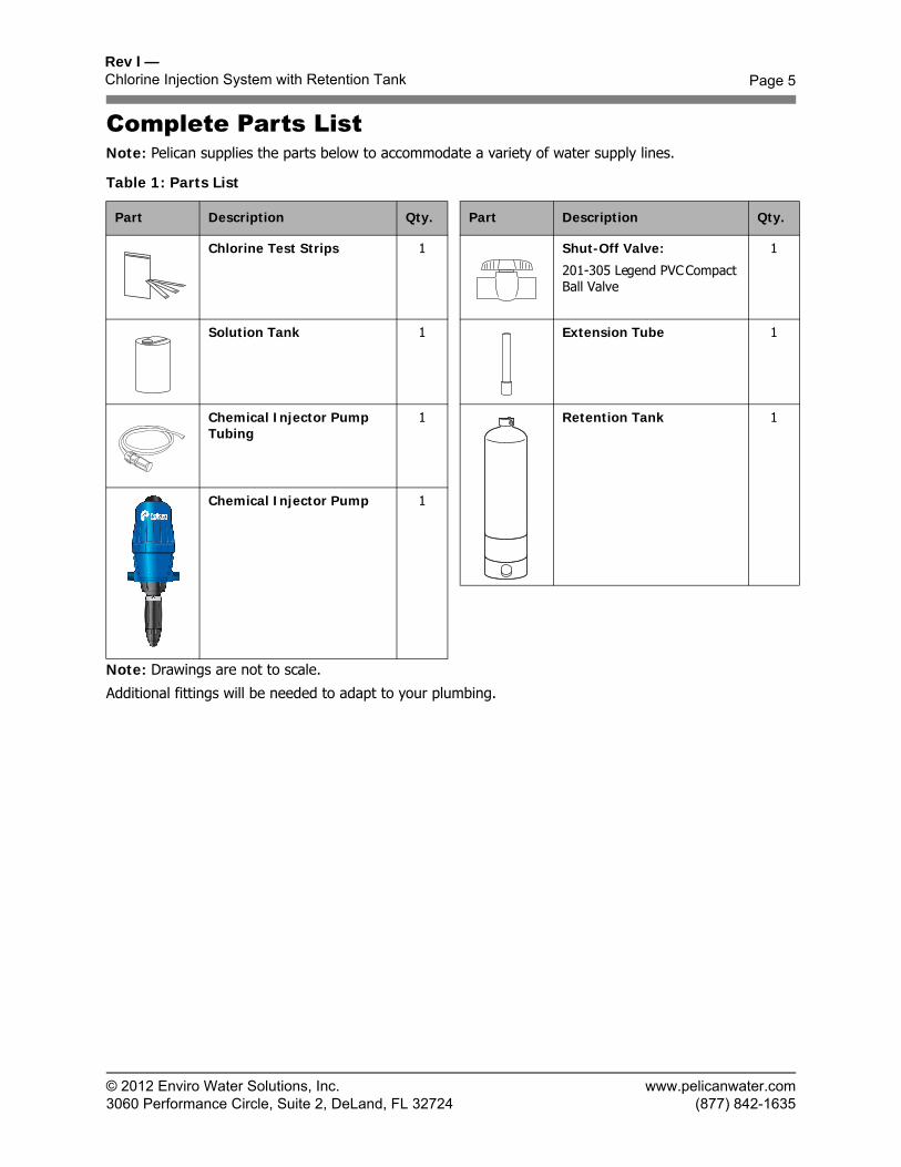
Complete Parts ListNote: Pelican supplies the parts below to accommodate a variety of water supply lines.
Table 1: Parts List
Note: Drawings are not to scale.
Additional fittings will be needed to adapt to your plumbing.
Part Description Qty. Part Description Qty.
Chlorine Test Strips 1 Shut-Off Valve:
201-305 Legend PVC CompactBall Valve
1
Solution Tank 1 Extension Tube 1
Chemical Injector Pump Tubing
1 Retention Tank 1
Chemical Injector Pump 1
Rev I —Chlorine Injection System with Retention Tank
© 2012 Enviro Water Solutions, Inc.3060 Performance Circle, Suite 2, DeLand, FL 32724
Page 6
www.pelicanwater.com(877) 842-1635
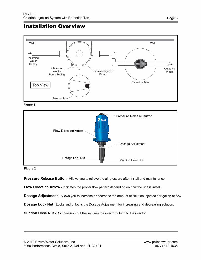
Installation Overview
Figure 1
IncomingWaterSupply
Solution Tank
Retention Tank
ChemicalInjector
Pump TubingChemical Injector
Pump
WallWall
INOU
T
INLET OUTLET
OutgoingWater
Dosage Adjustment
Dosage Lock Nut Suction Hose Nut
Pressure Release Button
Flow Direction Arrow
Figure 2
Pressure Release Button - Allows you to relieve the air pressure after install and maintenance.
Flow Direction Arrow - Indicates the proper flow pattern depending on how the unit is install.
Dosage Adjustment - Allows you to increase or decrease the amount of solution injected per gallon of flow.
Dosage Lock Nut - Locks and unlocks the Dosage Adjustment for increasing and decreasing solution.
Suction Hose Nut - Compression nut the secures the injector tubing to the injector.
Rev I —Chlorine Injection System with Retention Tank
© 2012 Enviro Water Solutions, Inc.3060 Performance Circle, Suite 2, DeLand, FL 32724
Page 7
www.pelicanwater.com(877) 842-1635
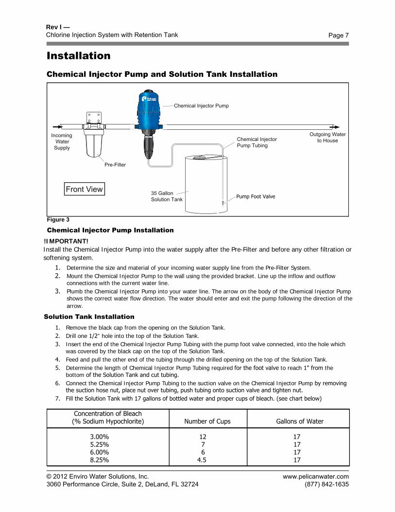
InstallationChemical Injector Pump and Solution Tank Installation
Figure 3
Chemical Injector Pump Installation
IncomingWater
Supply
Outgoing Waterto House
35 GallonSolution Tank
Chemical InjectorPump Tubing
Chemical Injector Pump
Pre-Filter
Pump Foot Valve
!IMPORTANT!Install the Chemical Injector Pump into the water supply after the Pre-Filter and before any other filtration or softening system.
1. Determine the size and material of your incoming water supply line from the Pre-Filter System.2. Mount the Chemical Injector Pump to the wall using the provided bracket. Line up the inflow and outflow
connections with the current water line.3. Plumb the Chemical Injector Pump into your water line. The arrow on the body of the Chemical Injector Pump
shows the correct water flow direction. The water should enter and exit the pump following the direction of the arrow.
Solution Tank Installation1. Remove the black cap from the opening on the Solution Tank.2. Drill one 1/2” hole into the top of the Solution Tank.3. Insert the end of the Chemical Injector Pump Tubing with the pump foot valve connected, into the hole which
was covered by the black cap on the top of the Solution Tank.4. Feed and pull the other end of the tubing through the drilled opening on the top of the Solution Tank.5. Determine the length of Chemical Injector Pump Tubing required for the foot valve to reach 1" from the
bottom of the Solution Tank and cut tubing.6. Connect the Chemical Injector Pump Tubing to the suction valve on the Chemical Injector Pump by removing
the suction hose nut, place nut over tubing, push tubing onto suction valve and tighten nut.7. Fill the Solution Tank with 17 gallons of bottled water and proper cups of bleach. (see chart below)
Concentration of Bleach (% Sodium Hypochlorite) Number of Cups Gallons of Water
3.00% 12 17 5.25% 7 17 6.00% 6 17 8.25% 4.5 17
Rev I —Chlorine Injection System with Retention Tank
© 2012 Enviro Water Solutions, Inc.3060 Performance Circle, Suite 2, DeLand, FL 32724
Page 8
www.pelicanwater.com(877) 842-1635
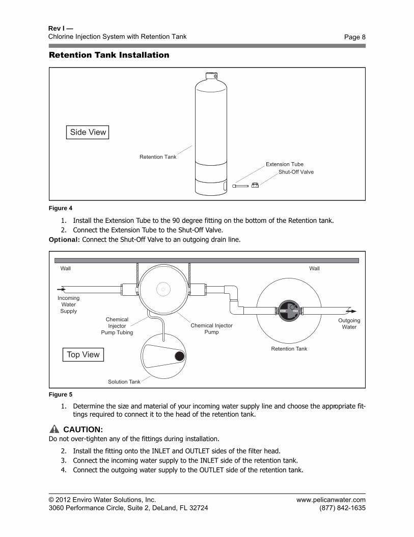
Retention Tank Installation
Figure 4
1. Install the Extension Tube to the 90 degree fitting on the bottom of the Retention tank.2. Connect the Extension Tube to the Shut-Off Valve.
Optional: Connect the Shut-Off Valve to an outgoing drain line.
Figure 5
1. Determine the size and material of your incoming water supply line and choose the appropriate fit-tings required to connect it to the head of the retention tank.
CAUTION:Do not over-tighten any of the fittings during installation.
2. Install the fitting onto the INLET and OUTLET sides of the filter head.3. Connect the incoming water supply to the INLET side of the retention tank.4. Connect the outgoing water supply to the OUTLET side of the retention tank.
Retention TankExtension Tube
Shut-Off Valve
Side View
IncomingWaterSupply
Solution Tank
Retention Tank
ChemicalInjector
Pump TubingChemical Injector
Pump
WallWall
INOU
T
INLET OUTLET
OutgoingWater
Rev I —Chlorine Injection System with Retention Tank
© 2012 Enviro Water Solutions, Inc.3060 Performance Circle, Suite 2, DeLand, FL 32724
Page 9
www.pelicanwater.com(877) 842-1635
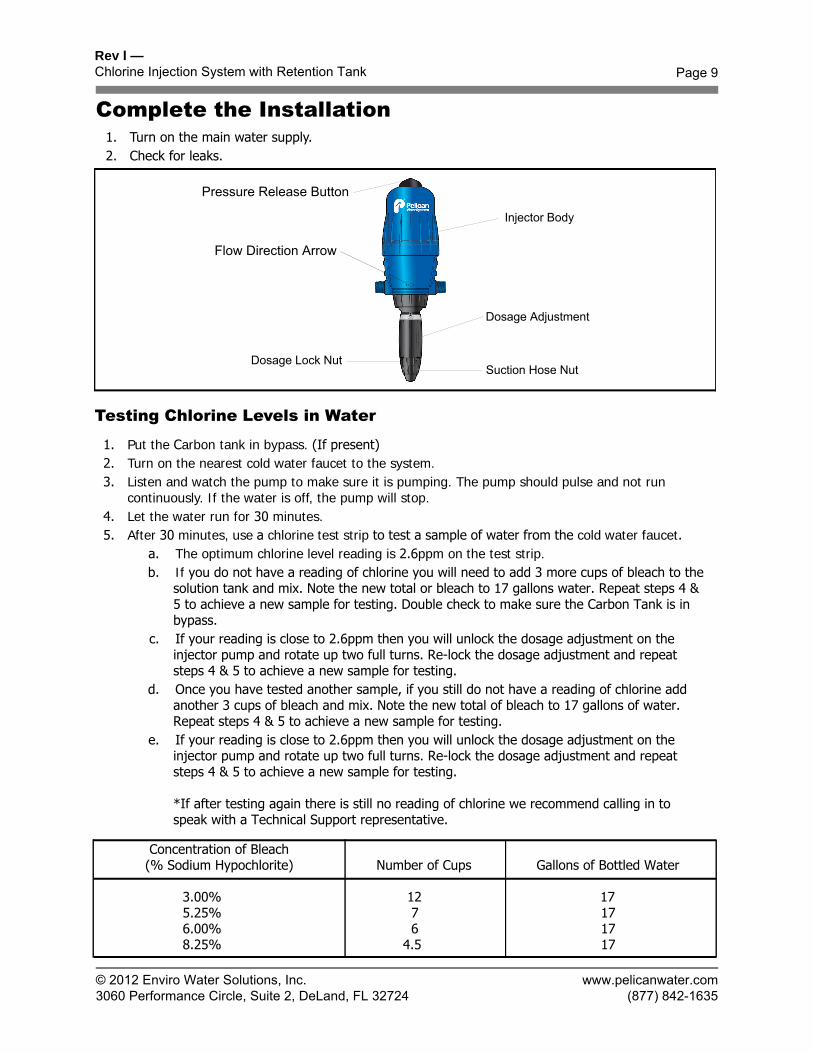
Complete the Installation1. Turn on the main water supply.2. Check for leaks.
Testing Chlorine Levels in Water
Concentration of Bleach (% Sodium Hypochlorite) Number of Cups Gallons of Bottled Water
3.00% 12 17 5.25% 7 17 6.00% 6 17 8.25% 4.5 17
1. Put the Carbon tank in bypass. (If present)2. Turn on the nearest cold water faucet to the system.3. Listen and watch the pump to make sure it is pumping. The pump should pulse and not run
continuously. If the water is off, the pump will stop.4. Let the water run for 30 minutes.5. After 30 minutes, use a chlorine test strip to test a sample of water from the cold water faucet.
a. The optimum chlorine level reading is 2.6ppm on the test strip.b. If you do not have a reading of chlorine you will need to add 3 more cups of bleach to the
solution tank and mix. Note the new total or bleach to 17 gallons water. Repeat steps 4 & 5 to achieve a new sample for testing. Double check to make sure the Carbon Tank is in bypass.
c. If your reading is close to 2.6ppm then you will unlock the dosage adjustment on the injector pump and rotate up two full turns. Re-lock the dosage adjustment and repeat steps 4 & 5 to achieve a new sample for testing.
d. Once you have tested another sample, if you still do not have a reading of chlorine add another 3 cups of bleach and mix. Note the new total of bleach to 17 gallons of water. Repeat steps 4 & 5 to achieve a new sample for testing.
e. If your reading is close to 2.6ppm then you will unlock the dosage adjustment on the injector pump and rotate up two full turns. Re-lock the dosage adjustment and repeat steps 4 & 5 to achieve a new sample for testing.
*If after testing again there is still no reading of chlorine we recommend calling in to speak with a Technical Support representative.
Dosage Adjustment
Dosage Lock Nut Suction Hose Nut
Pressure Release Button
Injector Body
Flow Direction Arrow
© 2012 Enviro Water Solutions, Inc.3060 Performance Circle, Suite 2, DeLand, FL 32724
Page 10
www.pelicanwater.com(877) 842-1635
Rev I —Chlorine Injection System with Retention Tank
Maintenance
Chemical Injector Pump:1. Change once a year (Injector Pump Seal Kit - 3 O-Rings & Check Valve)
NOTE: Spare kits for replacement purposes can be obtained by calling your customer service representative at Pelican Water.
Solution Tank Refill — Bleach & Water1. Check the level of the Solution Tank twice per month. Do not let the liquid in the tank fall below
¼ full.2. Fill the Solution Tank with bleach and treated water as needed. (Water that has gone through your
filtration system).
Rev I —Chlorine Injection System with Retention Tank
© 2012 Enviro Water Solutions, Inc.3060 Performance Circle, Suite 2, DeLand, FL 32724
Page 11
www.pelicanwater.com(877) 842-1635
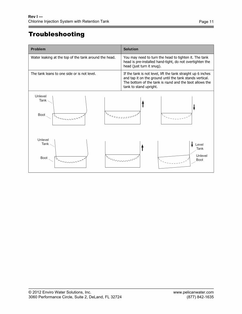
Troubleshooting
Problem Solution
Water leaking at the top of the tank around the head. You may need to turn the head to tighten it. The tank head is pre-installed hand-tight, do not overtighten the head (just turn it snug).
The tank leans to one side or is not level. If the tank is not level, lift the tank straight up 6 inches and tap it on the ground until the tank stands vertical. The bottom of the tank is round and the boot allows the tank to stand upright.
UnlevelTank
Boot
UnlevelTank
Boot
LevelTank
UnlevelBoot
Rev I —Chlorine Injection System with Retention Tank
© 2012 Enviro Water Solutions, Inc.3060 Performance Circle, Suite 2, DeLand, FL 32724
Page 12
www.pelicanwater.com(877) 842-1635
WarrantyPelican 5 Year Limited Warranty
Pelican Water ("Pelican") warrants to the end user ("customer") that its retention tanks and solid-state electronic heads ("Covered Items") will be free from defects in material and workmanship under normal use and service for a period of 5 years.
Pelican Dosatron Professional Chemical Injector Pump Warranty
Pelican Water ("Pelican") warrants to the end user ("customer") that its Dosatron Professional Chemical Injector Pump Motor (upper half of unit) will be free from defects in material and workmanship under normal use and service for a period of 1 year. The Dosatron Professional Chemical Injector Pump Adjustment Ratio Side (lower half of unit) will be free from defects in material and workmanship under normal use and service for a period of 90 days. The Chemical Injector Pump tubing is not covered as part of this warranty.
Limitations and Responsibilities
Pelican's obligation to the customer under these warranties shall be limited, at its option, to replacement or repair of Covered Items by these warranties, labor is not covered. Prior to return or repair of Covered Items, the customer must obtain a return goods authorization number from Pelican and at Pelicans option, return the Covered Items freight prepaid. Any Covered Item repaired or replaced under these warranties will be returned prepaid standard freight to the original point of shipment. Expedited freight options are available at customer expense.
No warranty is made with respect to defects or damaged due to neglect, misuse, alterations, accident, misapplication, physical damage, or damaged caused by fire, acts of God, or freezing. These warranties apply only to the original registered owner so long as the owner owns the home in which the unit was originally installed. Customer must register their system with Pelican within 90 days of purchase* in order to obtain a warranty. Warranty will discontinue after the unit is removed from the location where it was originally installed. Warranty begins on the date of delivery of product to the customer. Improper maintenance of system (i.e. not replacing filters or media) on time will be considered "neglect". Installation of any system on water conditions outside of or beyond the recommended specs of any system voids any warranty.
Pelican gives this warranty to the customer in lieu of all other warranties, express or implied, including without limitation any implied warranties of merchantability or fitness for a particular purpose or treatment of certain water and hereby expressly disclaims all other such warranties. Pelican's liability hereunder shall not exceed the cost of the product. Under no circumstances will Pelican be liable for any incidental or consequential damages or for any other loss, damage or expense of any kind, including loss of use, arising in connection with the installation or use or inability to use the Covered Items or any water treatment system the Covered Items are incorporated into. These warranties are governed by the laws of the state of Florida and may change at any time without notice.
*Failure by California and Quebec residents to complete the product registration form does not diminish their warranty rights.
**For all orders placed on or after June 3rd, 2011.
Rev I —Chlorine Injection System with Retention Tank
© 2012 Enviro Water Solutions, Inc.3060 Performance Circle, Suite 2, DeLand, FL 32724
Page 13
www.pelicanwater.com(877) 842-1635
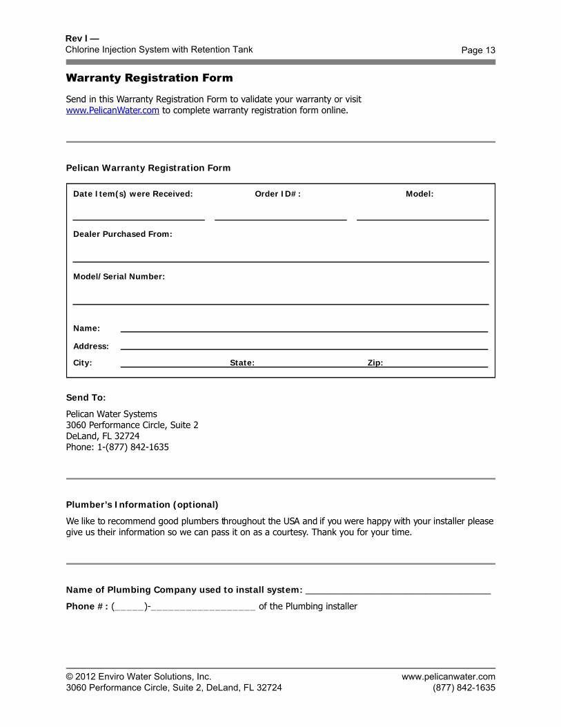
Warranty Registration Form
Send in this Warranty Registration Form to validate your warranty or visitwww.PelicanWater.com to complete warranty registration form online.
Pelican Warranty Registration Form
Send To:
Pelican Water Systems3060 Performance Circle, Suite 2DeLand, FL 32724Phone: 1-(877) 842-1635
Plumber’s Information (optional)
We like to recommend good plumbers throughout the USA and if you were happy with your installer please give us their information so we can pass it on as a courtesy. Thank you for your time.
Name of Plumbing Company used to install system: _____________________________________
Phone #: (_____)-__________________ of the Plumbing installer
Date Item(s) were Received: Order ID#: Model:
Dealer Purchased From:
Name:
Address:
City: State: Zip:
Model/Serial Number: