owner’s manual - water softener & hvac utah | …€¦ · owner’s manual ecowater systems...
TRANSCRIPT

OWNER’S MANUAL
EcoWater Systems LLCP.O. Box 64420, St. Paul, MN 55164-0420
1-800-86WATER Part No. 7333048 (Rev. A 4/24/12)
Systems tested and certified by NSF International againstNSF/ANSI Standard 44 for water softener performanceand the reduction of barium and radium 226/228.
Systems tested and certified by the Water QualityAssociation against NSF/ANSI Standard 44 for
hardness reduction, efficiency and the reduction ofbarium and radium 226/228; and against CSA B483.1.
ERR 3500R20 & ERR 3502R30 areTested and Certified by WQA against
NSF/ANSI Standard 42 for chlorine taste and odor.
How to operate your EcoWater SystemsWater Conditioner/Refiner
EcoWater Systems Conditionerwith Remote (ECR)
EcoWater Systems Refinerwith Remote (ERR)
SERIES 3500 & 3502

2
SAFETY GUIDESFollow the installation instructions carefully. Failure toinstall the EcoWater Systems conditioner/refiner proper-ly voids the warranty.Before you begin installation, read this entire manual.Then, obtain all the materials and tools you will need tomake the installation.Check local plumbing and electrical codes. Theinstallation must conform to them.Use only lead-free solder and flux for all sweat-solderconnections, as required by state and federal codes.Use care when handling the EcoWater Systems condi-tioner/refiner. Do not turn upside down, drop, or set onsharp protrusions.Do not locate the EcoWater Systems conditioner/refinerwhere freezing temperatures occur. Do not attempt totreat water over 120°F. Freezing, or hot water damagevoids the warranty.Avoid installing in direct sunlight. Excessive sun heatmay cause distortion or other damage to non-metallicparts.The EcoWater Systems conditioner/refiner requires aminimum water flow of 3 gallons per minute at the inlet.Maximum allowable inlet water pressure is 125 psi. Ifdaytime pressure is over 80 psi, nighttime pressure mayexceed the maximum. Use a pressure reducing valve ifnecessary (Adding a pressure reducing valve mayreduce the flow).The EcoWater Systems conditioner/refiner works on 24volt, 60 Hz electrical power only. Be sure to use theincluded transformer and plug it into a nominal 120V, 60Hz household outlet that is in a dry location only,grounded and properly protected by an over currentdevice such as a circuit breaker or fuse. If transformer isreplaced, use only the authorized service, Class II, 24V,10 VA transformer.
This system is not intended to be used for treating waterthat is microbiologically unsafe or of unknown qualitywithout adequate disinfection before or after the system.If conditioner/refiner is being used to reduce bariumand/or radium 226 and 228, please verify performanceby contacting 651-607-1700, ext. 6470 for testing treatedwater supply or check the water testing section of yourlocal phone directory.NOTE: This equipment has been tested and found tocomply with the limits for a Class B digital device, pur-suant to Part 15 of the FCC Rules. These limits aredesigned to provide reasonable protection against harm-ful interference in a residential installation. This equip-ment generates, uses, and can radiate radio frequencyenergy and, if not installed and used in accordance withthe instructions may cause harmful interference to radiocommunications. However, there is no guarantee thatinterference will not occur in a particular installation. Ifthis equipment does cause harmful interference to radioor television reception, which can be determined by turn-ing the equipment off and on, the user is encouraged totry to correct the interference by one or more of the fol-lowing measures:= Reorient or relocate the receiving antenna.= Increase the separation between the equipment andreceiver.
= Connect the equipment into an outlet on a circuit dif-ferent from that to which the receiver is connected.
= Consult the dealer or an experienced radio/TV tech-nician for help.
Changes or modifications not expressly approved byEcoWater Systems could void the user’s authority tooperate the equipment.This device complies with Industry Canada StandardRSS-210. Operation is subject to the following two con-ditions: (1) this device may not cause interference, and(2) this device must accept any interference, includinginterference that may cause undesired operation of thedevice.Ce dispositif est conforme avec la norme CNR-210d’Industrie Canada. Le fonctionnement du dispositifest sujet aux deux conditions suivantes: (1) le dispositifne doit pas causer de brouillage, et (2) le dispositif doitaccepter tous brouillages, incluant tous brouillages quipeut nuire au bon fonctionnement du dispositif.
European Directive 2002/96/EC requires allelectrical and electronic equipment to be dis-posed of according to Waste Electrical andElectronic Equipment (WEEE) requirements.This directive or similar laws are in placenationally and can vary from region to region.Please refer to your state and local laws forproper disposal of the equipment.
TABLE OF CONTENTS PageWarranty . . . . . . . . . . . . . . . . . . . . . . . . . . . . . . . . . . .3Guarantees . . . . . . . . . . . . . . . . . . . . . . . . . . . . . . . . .4Planning Installation . . . . . . . . . . . . . . . . . . . . . . . . . .5Unpacking . . . . . . . . . . . . . . . . . . . . . . . . . . . . . . . . . .6Installation . . . . . . . . . . . . . . . . . . . . . . . . . . . . . . . .6-8Conditioner/Refiner Operation . . . . . . . . . . . . . . . .9-23Remote Operation . . . . . . . . . . . . . . . . . . . . . . . .24-32Service Information . . . . . . . . . . . . . . . . . . . . . . .33-35Refilling with Salt . . . . . . . . . . . . . . . . . . . . . . . . . . .33Troubleshooting . . . . . . . . . . . . . . . . . . . . . . . . . .36-38Dimensions & Schematic . . . . . . . . . . . . . . . . . . . . .39Specifications & Performance Claims . . . . . . . . .40-41Repair Parts . . . . . . . . . . . . . . . . . . . . . . . . . . . . .42-45
ECOWATERS Y S T E M S Table of Contents & Safety Guides

3
ECOWATERS Y S T E M S Warranty
LIMITED WARRANTYEcoWater Systems LLC Advantage Warranty
Series ECR & ERR 3500 Water SystemCongratulations! You have just purchased the highest quality water conditioning product on the market. To register your war-ranty, complete the enclosed Warranty Registration Card and mail it within 30 days of purchase.To whom is this warranty extended?EcoWater Systems LLC warrants its products to the original owner and guarantees that the products will be free from defectsin materials and workmanship from the original date of installation.How does my warranty work?If, during the respective warranty period, a part proves, after inspection by EcoWater, to be defective, EcoWater will, at its soleoption repair or replace that part at no charge, other than normal shipping, installation or service charges.What is covered by the warranty?EcoWater Systems LLC guarantees that,for the LIFETIME of the original owner, the SALT TANK and the MINERAL TANK will not rust, corrode, leak, burst, or in anyother manner fail to perform their proper functions and that,for a period of TEN YEARS, the VALVE BODY will be free of defects in materials and workmanship and will perform its properfunction and that,for a period of FIVE YEARS, the ELECTRONIC FACEPLATE and ALL OTHER PARTS, including the HYDROLINK™ REMOTEwill be free of defects in materials and workmanship and will perform their normal functions.Only on models designated as ERR on the rating decal, is the media bed guaranteed, for the lifetime of the original owner, tobe free of defects in materials and workmanship and to remove chlorine taste and odor from a municipal water supply.How do I obtain warranty service?Should you need service, your local, independent EcoWater Dealer is only a phone call away.PHONE:____________________________________________________________To obtain warranty service, notice must be given, within thirty (30) days of the discovery of the defect, to your local EcoWaterSystems dealer.If I need a part replaced after the factory warranty expires, is the replacement part warranted?Yes, EcoWater Systems LLC warrants FACTORY REPAIRS as well as all REPLACEMENT PARTS for a period of 90 DAYS.This warranty does not include normal shipping, installation or service charges.Are any additional warranties available?We are pleased to say, YES! EcoWater Systems LLC sells an EXTENDED, PARTS ONLY WARRANTY for the ELECTRON-ICS portion of your product. This warranty is called the "Perfect Ten" and extends the five year warranty on the electronic FACE-PLATE, WIRING HARNESS, DRIVE MOTOR, TRANSFORMER, POWER CORD, SENSOR HOUSING, and MICRO SWITCH-ES to a total of TEN YEARS from the date of original installation. Your local dealer will provide details regarding this warrantyor will refer you to the factory for additional information. In addition, the 3500 SERIES product carries the CREST OF EXCEL-LENCE GUARANTEE that, should you experience a repetitive problem that remains uncorrected, EcoWater will, during theFIRST YEAR OF INSTALLATION, replace the product with the exact or comparable product.* This guarantee may be subjectto normal shipping and installation or service charges.General ProvisionsThe above warranties are effective provided the water conditioner/refiner is operated at water pressures not exceeding 125 psi,and at water temperatures not exceeding 120°F (and on a municipal chlorinated water supply - models designated as ERR onthe rating decal); provided further that the water conditioner/refiner is not subject to abuse, misuse, alteration, neglect, freezing,accident or negligence; and provided further that the water conditioner/refiner is not damaged as the result of any unusual forceof nature such as, but not limited to, flood, hurricane, tornado or earthquake. EcoWater Systems LLC is excused if failure toperform its warranty obligations is the result of strikes, government regulation, materials shortages, or other circumstancesbeyond its control.*THERE ARE NO WARRANTIES ON THE WATER CONDITIONER/REFINER BEYOND THOSE SPECIFICALLY DESCRIBED ABOVE. ALLIMPLIED WARRANTIES, INCLUDING ANY IMPLIED WARRANTY OF MERCHANTABILITY OR OF FITNESS FOR A PARTICULAR PUR-POSE, ARE DISCLAIMED TO THE EXTENT THEY MIGHT EXTEND BEYOND THE ABOVE PERIODS. THE SOLE OBLIGATION OF ECOW-ATER SYSTEMS LLC UNDER THESE WARRANTIES IS TO REPLACE OR REPAIR THE COMPONENT OR PART WHICH PROVES TO BEDEFECTIVE WITHIN THE SPECIFIED TIME PERIOD, AND ECOWATER IS NOT LIABLE FOR CONSEQUENTIAL OR INCIDENTAL DAM-AGES. NO ECOWATER DEALER, AGENT, REPRESENTATIVE, OR OTHER PERSON IS AUTHORIZED TO EXTEND OR EXPAND THEWARRANTIES EXPRESSLY DESCRIBED ABOVE.Some states do not allow limitations on how long an implied warranty lasts or exclusions or limitations of incidental or conse-quential damage, so the limitations and exclusions in this warranty may not apply to you. This warranty gives you specific legalrights, and you may have other rights which vary from state to state. This warranty applies to consumer-owned installations only.

4
GUARANTEE BONDThe Safeco Insurance Company of America has issued its bond in the form shown below, guaranteeing full performance byEcoWater Systems LLC.SAFECO INSURANCE COMPANY OF AMERICA, hereinafter called “Surety,” guarantees unto Bank of New York as Trusteeholding said Guarantee Bond under the terms of a Trust Agreement dated April 9, 2003, for the use and benefit of originalpurchasers of residential EcoWater Systems Units within the Continental United States, as described herein, that EcoWaterSystems LLC will discharge the obligations of the “EcoWater Bonded Parts and Service Guarantee Policy.”PROVIDED, HOWEVER, that:1. Liability of Surety hereunder shall not exceed the sum of FIVE HUNDRED AND 00/100th DOLLARS ($500.00) as to anyone installation, and shall not exceed the sum of FIVE HUNDRED THOUSAND AND 00/100th DOLLARS ($500,000.00) inthe aggregate, and2. There shall be no liability hereunder as to any purchaser to whom there has not been issued at the time of installation andpurchase completed registration card which is enclosed with a facsimile of this bond, and who has not returned such card inaccordance with this guarantee.3. Claim must be made by such original purchaser in writing within 30 days from the expiration of these guarantees uponEcoWater Systems LLC, P.O. Box 64420, St. Paul, MN 55164, to perform the terms of said guarantee, and notice of anydefault on such guarantee must be sent to Surety at its address by Registered Mail.
SAFECO INSURANCE COMPANY OF AMERICAThis is to certify that the original of the above guarantee and bond is on file with Bank of New York.
BANK OF NEW YORKAs Trustee
ECOWATERS Y S T E M S Guarantees
Crest of ExcellenceGUARANTEE
for the EcoWater Series ECR/ERR 3500/3502 Water Systems
Satisfied customers are our most valuable asset, and EcoWater has been dedicated to the manufactureof the highest quality water conditioning equipment and to the satisfaction of its customers for over 80years. When you purchase EcoWater equipment you’re buying quality; and that is exactly what we expectyou to receive!The Crest of Excellence Performance Guarantee assures you that satisfying customers is our primary con-cern, and allows you to feel secure and confident with the quality of your purchase.If during the first year of installation, the unit does not perform the function for which it was designed, andthe repetitive problem remains uncorrected, we will – under the Crest of Excellence Performance Guaran -tee and at no charge to you – replace the unit with identical equipment or with equipment of comparablefeatures and capabilities.The Crest of Excellence Performance Guarantee applies to new equipment which is purchased and serv-iced through Authorized EcoWater Dealers, and is not applicable to equipment which is damaged ordestroyed by forces of nature, abuse, neglect or misuse.It’s just that easy! Quality and satisfaction are what you are buying and the Crest of ExcellencePerformance Guarantee is our promise that you’ll get what you pay for!

5
INLET / OUTLET PLUMBING OPTIONS= ALWAYS INSTALL either an EcoWater Systems bypassvalve #7214383, or a 3-valve bypass system. Bypassvalves allow you to turn off water to the conditioner/refiner for repairs if needed, but still have water inhouse pipes.
OTHER REQUIREMENTS= A drain is needed for recharge discharge water. A floordrain is preferred, close to the EcoWater Systemsconditioner/refiner. A laundry tub, standpipe, etc., areother options (See Figure 1B).
= A 120V, 60 Hz, grounded, continuously “live” electricaloutlet is needed, in a dry location within 10 feet of theEcoWater Systems conditioner/refiner.
NOTE: The Commonwealth of Massachusetts plumbingcode 248-CMR shall be adhered to. A licensed plumbershall be used for this installation.
floor drain
valve drain hose
brinetankoverflowhose
TWO--TANKMODEL
1--1/2”airgap
INLET
OUTLET
3-- valvebypass system
inlet valve
outlet valve
bypass valve
floor drain
NOTE: Faceplate and supportnot shown for clarity of drawing.
Tie or wire valve drain hose in placeto keep over floor drain.
brine tankoverflow hose
valve drain hose
CABINETMODEL
1--1/2”airgap
120V, 60Hzoutlet
transformer(supplied)
tocontroller
INLET
OUTLET
HARDWATERHARD
WATER
CONDITIONEDWATER
bypass valve#7214383
tocontroller
FIG. 1
TYPICAL INSTALLATION DRAWINGS
ECOWATERS Y S T E M S Planning Installation
STANDPIPE
1--1/2”airgap
drainhose
1--1/2”airgap
drainhose
LAUNDRY TUB
DRAIN OPTIONS
FIG. 1B

6
e. Make sure the brine tank cover is properly positioned onthe tank.3. INSTALL BYPASS VALVE and/or COPPERTUBES
a. If installing an EcoWater Systems Bypass Valve, putlubricated o-ring seals onto both bypass valve ports (SeeFigure 3B). Carefully slide the bypass valve into the condi-tioner/refiner valve and install the "C" clips.b. Slide a lubricated o-ring seal onto each of the coppertubes. Carefully insert the copper tubes into the bypass valve(See Figure 3B), or into the conditioner/refiner valve (Figures3 & 3A). Then install the “C'' clips.NOTE: For lubrication, use silicone grease approved forpotable water supplies.4. TURN OFF WATER SUPPLYa. Close the main water supply valve near the well pump orwater meter.b. Shut off the electric or fuel supply to the water heater.c. Open high and low faucets to drain all water from thehouse pipes.5. INSTALLING THREE-VALVE BYPASSIf installing a 3-valve bypass system, plumb as needed usingFigure 1 as a guide. When installing sweat copper, be sure touse lead-free solder and flux, required by federal and statecodes. Use pipe joint compound on outside pipe threads.6. ASSEMBLE INLET & OUTLET PLUMBINGMeasure, cut, and loosely assemble pipe and fittings from themain water pipe (or from the bypass valves installed in Step5), to the inlet and outlet copper tubes, installed in Step 3b.Be sure hard water supply pipe goes to the valve inlet side.Trace the water flow direction to be sure.
1. UNPACKINGEcoWater Systems conditioner models R70 and R50S areshipped from the factory in two cartons. These contain resintank/controller assembly in one carton and the brine tank,cover, bag(s) of small parts needed to assemble and installthe unit, plus this manual, in the other.EcoWater Systems conditioner/refiner models R20, R30 andR40 are shipped from the factory in one master carton. Thecarton also includes a bag of small parts needed to assembleand install the unit, plus this manual.Thoroughly check the EcoWater Systems conditioner/refinerfor possible shipping damage and parts loss. Also inspectand note any damage to the shipping carton. Notify the trans-portation company if damage is present. EcoWater Systemsis not responsible for in-transit damages.Remove and discard (RECYCLE) all packing materials. Wesuggest you keep the small parts in the bag(s) until you areready to use them.2. BRINE TANK (on two-tank models)a. Locate the brinewell in position. On the brine tank, locatethe slots at the bottom of the brinewell, toward the tank wall,as shown in Figure 2. Then use the screw and washer (inparts bag) to fasten the brinewell in place.b. Lower the brine valve into the brinewell. Push the tubinginto the brinewell top slot (Fig. 2) and route it out of the brinetank through the smaller hole in the rear wall of the brine tank.c. Install the brinewell cover.d. Take the rubber grommet and hose adaptor elbow from theparts bag. Push grommet into the larger hole in the rear wallof the brine tank. Then insert the larger diameter end of theelbow through the grommet.
FIG. 3
ECOWATERS Y S T E M S Unpacking & Installation
FIG. 2
screw
slots
brine valve
brinewell
brine tank
brine tubing
elbow
grommet
washer
brinewell cover
standtube
float stem
o--ring (2)
turbinesupport
clip (2)
copper tube (2)
VALVE INLET
coppertube
o--ring
clipturbinesupport
A.
B.
BypassValveInstallation
coppertube (2)
o--ring (2)

7
7. CONNECT INLET & OUTLET PLUMBINGa. SOLDERED COPPER(1) Thoroughly clean and flux all joints.(2) Pull the plastic “C'' clips and remove the inlet and outlettubes from the valve. Remove o-rings from the tubes. DONOT solder with tubes in the valve. Soldering heat willdamage the valve.NOTE: If installing a ground as shown in Figure 4A, placeground clamps on copper tubes before soldering (See Step7a).(3) Make all solder connections. Be sure to keep fittings fullytogether, and pipes square and straight.b. THREADED PIPE(1) Apply pipe joint compound to all outside pipe threads.(2) Tighten all threaded joints.(3) If soldering to the inlet and outlet tubes, observe Step 7aabove.c. CPVC PLASTIC PIPE(1) Clean, prime and cement all joints, following the manufac-turer's instructions supplied with the plastic pipe and fittings.(2) If soldering to the inlet and outlet tubes, observe Step 7aabove.
8. COLD WATER PIPE GROUNDINGThe house cold water pipe (metal only) is often used as aground for the house electrical system. The 3-valve bypasstype of installation, shown in Figure 1, will maintain groundcontinuity. If you use the plastic bypass, continuity is broken.To restore the ground, do either step 8a or 8b following.a. Use the ground clamp kit (included) to make a jumperacross the inlet and outlet copper tubes (See Figure 4A).
b. Install a #4 copper wire across the removed section ofmain water pipe, securely clamping at both ends (See Figure4B) – parts not included.
9. INSTALL VALVE DRAIN HOSENOTE: See valve drain options on Page 5.a. Elevating the drain hose may cause back pressure thatcould reduce the brine draw during recharge. If raising thedrain line overhead is required to get to the drain point, meas-ure the inlet water pressure to the conditioner/refiner first. Forinlet pressures between 20 and 50 psi, do not raise higherthan 8 feet above the floor. For inlet pressure above 50 psi,the drain line may be raised to a maximum height of 14 feet.b. Connect a length of 1/2" I.D. hose (check codes) to thevalve drain elbow, on the controller. Use a hose clamp tohold the hose in place. Route the hose out through the notchin the back of the top cover.c. Run the hose to the floor drain, and as typically shown inFigure 1, tie or wire the end to a brick or other heavy object.This will prevent “whipping” during recharges. Be sure to pro-vide a 1-1/2" minimum air gap, to prevent possible sewerwater backup.
10. INSTALL BRINE TANK OVERFLOWHOSE
a. Connect a length of 1/2" I. D. hose to the brine tank over-flow elbow and secure in place with a hose clamp.b. Run the hose to the floor drain, or other suitable drain pointno higher than the drain fitting on the tank. If the tankoverfills with water, the excess water flows to the drain point.
11. On Two-tank models, connect the brine tubingto the nozzle and venturi housing.
FIG. 4 FIG. 5 FIG. 6
ECOWATERS Y S T E M S Installation
D
ground wire
clamp (2)
nozzle &venturi
o--ring
Note: To ease brine tubing con-nection, use the elbow and o--ringseal as shown. Lubricate the o--ring and insert into the elbow. Turnthe elbow on and tighten. Then,back--off up to one turn, as need-ed.
B
A3 -- Valve Bypass
OUTLETVALVE
INLETVALVE
BYPASSVALVE
refinerrefiner
EcoWater SystemsBypass Valve
D for SERVICE:-- Open the inlet and outlet
valves.-- Close the bypass valve.
for BYPASS:-- Close the inlet and outlet
valves.-- Open the bypass valve.
PUSH INfor bypass
PULL OUTfor servicenut--ferrule
screen
groundclamp
tubingto conditioner/
from conditioner/

8
12. PRESSURE TESTING FOR LEAKSTo prevent excessive air pressure in the EcoWaterSystems conditioner/refiner and plumbing system, dothe following steps EXACTLY in order:a. Fully open two or more conditioned cold water faucetsnearby the EcoWater Systems conditioner/refiner.b. Place the bypass valve(s) in bypass position (SeeFigure 6).c. Fully open the main water supply valve. Watch until theflow from the opened faucets becomes steady, with nospurting or air bubbles.d. EXACTLY as follows, place bypass valve(s) into serv-ice:(1) SINGLE BYPASS VALVE: Slowly move the valvestem toward service position, pausing several times toallow the unit to pressurize slowly.(2) 3-VALVE BYPASS: Fully close the bypass valve andopen the outlet valve. Slowly open the inlet valve,pausing several times to allow the unit to pressurizeslowly.
e. After about three minutes, open a hot water faucet forone minute, or until all air is expelled, then close.f. Close all cold water faucets and check your plumbing workfor leaks.13. RINSING OUT CARBON FINES (Refiner
models only)In refiners (ERR series), small particles of carbon filtrationmaterial are generated during manufacturing and shippingwhich will exit the media tank with the first water flow. Thesecarbon “fines” are not harmful, but give the water a gray colorand should be rinsed down the drain before any water fromthe refiner is directed to the home’s faucets or water heater.a. Make sure the refiner’s valve drain hose is hooked up andthe open end directed to a floor drain, laundry tub or othersuitable type of drain.
b. Make sure the refiner’s bypass valve is in the bypass posi-tion.
c. Plug in the transformer.d. Initiate a recharge, and advance the valve to the back-wash position.
e. Once the unit is in backwash, slowly open the bypassvalve into the service position.
f. Let the refiner complete the backwash and fast rinse cycles(takes 10-12 minutes). When the recharge cycle ends, therefiner valve returns to the service position.
14. ADD WATER AND SALT TO THE BRINETANK
a. Using a pail or garden hose, add about 3 gallons ofwater into the brine tank. DO NOT pour into the brinewell.b. Add salt to the brine tank. It is recommended to fill thebrine tank no more than 1/2 full. Level the salt when fin-ished adding. You can use most water conditioner salts,but it must be clean. Recommended nugget, pellet orcoarse solar salts have less than 1% impurities. Salt stor-
age capacity is shown on page 39.NOTE: See page 33 for additional information on salt.15. CONNECT TRANSFORMERPlug the transformer into a continuously “live,” grounded,120V, 60Hz house electrical outlet, in a dry location andapproved by local codes. The unit works on 24V only. Donot connect without the transformer.16. PROGRAM THE ELECTRONIC CON-
TROLLERFollow the Setup Procedure on Page 9 to program the elec-tronic controller with basic operating information, such as timeand water hardness. After completing Steps 1 through 14 ofthe setup procedure on Page 9, continue with Step 17 below.17. SANITIZING THE ECOWATER SYSTEMS
CONDITIONER/REFINERCare is taken at the factory to keep your EcoWater Systemsconditioner/refiner clean and sanitary. However, during ship-ping, storage, installing and operating, bacteria could get intothe unit. For this reason, sanitizing as follows is suggested*when installing.a. Remove the brinewell cover and pour about 1-1/2 oz. (2 to3 tablespoons) of common household bleach into the condi-tioner/refiner brinewell. Clorox, Linco, Bo Peep, White Sail,Eagle, etc., are brand names of bleach readily available.Replace the brinewell cover.b. Make sure the bypass valve is in the service position.c. Start a recharge: From the rolling status screens, pressthe SELECT (¡) button to display the Main menu. Makesure Recharge is highlighted, then press SELECT (¡). PressDOWN (6) to scroll to Recharge Now, then press SELECT(¡) twice. You should hear the valve motor run as the condi-tioner/refiner begins recharging. This recharge draws thesanitizing bleach into and through the conditioner/refiner. Anyair remaining in the unit is purged to the drain.d. After the recharge has completed, fully open a cold waterfaucet, downstream from the conditioner/refiner, and allow 50gallons of water to pass through the system. This should takeat least 20 minutes. Close the faucet.18. RESTART THE WATER HEATERTurn on the electric or fuel supply to the water heater, andlight the pilot, if applies.NOTE: The water heater is filled with hard water and, as hotwater is used, it refills with conditioned water. In a few days,the hot water will be fully conditioned. To have fully condi-tioned hot water immediately, wait until the recharge (Step 17)is complete, then drain the water heater until water runs cold.19. CONNECT TO THE REMOTEUnpack the remote and install the batteries, as detailed onPage 24. Then, follow the “Connecting to Remote” procedureon Page 11.*Recommended by the Water Quality Association. On some watersupplies, the EcoWater Systems unit may need periodic disinfecting.
ECOWATERS Y S T E M S Installation

9
SETUP PROCEDUREWhen the EcoWater Systems conditioner/refiner isplugged in for the first time, a beep sounds and the dis-play briefly shows a logo, followed by model informa-tion. Next, a series of six “wizard” screens prompts youto enter basic operating information:
FIG. 81. LANGUAGE If the desired language already has ablack dot next to it (See Figure 8), go to Step 2.Otherwise, press the conditioner/refiner’s DOWN (6)or UP (5) buttons to scroll to the desired language,then press the SELECT (¡) button to choose it.
2. Press the SELECT (¡) button to advance to the next“wizard” screen.
FIG. 93. SYSTEM UNITS If the desired system already has ablack dot next to it (See Figure 9), go to Step 4.Otherwise, press the DOWN (6) or UP (5) buttonsto scroll to the desired system, then press theSELECT (¡) button to choose it.
4. Press the SELECT (¡) button.
FIG. 10
FIG. 11
FIG. 12
FIG. 13
FIG. 14
6. Press the SELECT (¡) button.
8. Press the SELECT (¡) button.
9. SALT LEVEL Press the UP (5) or DOWN (6) but-tons to set the salt level (See Figure 12). It shouldmatch the lowest number visible on the brinewelldecal above the salt.
10. Press the SELECT (¡) button.
11. IRON LEVEL Press the UP (5) or DOWN (6) but-tons to set the value for iron in your water (SeeFigure 13). The conversion factor is 3 grains per 1ppm of clear water iron.
12. Press the SELECT (¡) button. The screen willshow “Setup complete!” (See Figure 14).
13. If, at this point, you want to go back and makechanges, press the DOWN (6) button to scroll toRedo setup, then press the SELECT (¡) buttontwice to repeat the six “wizard” screens.
14. If no changes are desired, make sure Run softenerhas a black dot next to it (See Figure 14) and pressthe SELECT (¡) button. The unit begins normaloperation, described on the next page.
FIG. 7
Display LEFTButton
RIGHTButton
UPButton
DOWNButton
E.A.S.E.Port
SELECTButton
5. CURRENT TIME Press the DOWN (6) or UP (5)buttons to set the current time (See Figure 10). Holdthe button down to rapidly advance. Be sure that AMor PM is correct. If the system units were set to met-ric in Step 3, the clock will be in 24-hour format.
ECOWATERS Y S T E M S Conditioner/Refiner Operation
NOTE: Do not increase the hardness setting tocompensate for iron in your water. Theelectronic control compensates automaticallyafter you set the iron level in Step 11, below.
7. HARDNESS Press the UP (5) or DOWN (6) but-tons to set the value of your water’s hardness (SeeFigure 11).

10
During normal operation (status screens rolling), pressthe conditioner/refiner’s SELECT (¡) button to displaythe Main menu (See Figure 16). This menu and itssubsidiary screens are used to control these operations:
=Recharge (See Page 14)=Salt settings
=Salt level (See Page 13)=Low salt alarm (See Page 13)=Salt type (See Page 13)
=Basic settings=Current time (See Page 14)=Hardness (See Page 15)=Iron level (See Page 15)=Recharge time (See Page 15)=Rolling screens (See Page 16)
=User preferences=Language (See Page 16)=Time format (See Page 17)=Volume units (See Page 17)=Hardness units (See Page 17)=Weight units (See Page 17)
=System information=Model information (See Page 18)=Water available (See Page 18)=Daily avg. water used (See Page 18)=Water used today (See Page 18)=Total water used (See Page 18)=Current water flow (See Page 18)=Days powered up (See Page 18)=Last recharge (See Page 18)=Total recharges (See Page 18)
=Advanced settings=Cycle times
=Backwash time (See Page 19)=2nd backwash (On/Off) (See Page 19)=2nd backwash time (See Page 19)=Fast rinse time (See Page 19)
=Special features=Efficiency mode (See Page 20)=Max. days between recharges (See Page 20)=Auxiliary control (See Page 21)=Chemical feed volume** (See Page 21)=Chemical feed timer** (See Page 21)=97% feature (See Page 20)=Service reminder (See Page 22)
=Troubleshooting=Send E.A.S.E. message (See Page 22)=Diagnostics (See Page 23)=Setup changes (See Page 23)
=Connect to remote (See Page 11)**Only displayed if Auxiliary control is set to Chemical feed.
FIG. 16
MAIN MENU
Pressing the conditioner/refiner’s RIGHT (4) buttonmanually advances to the next screen in the sequence.Pressing the LEFT (3) button manually returns to theprevious status screen. If no buttons are pressed for 30seconds, the automatic rolling sequence resumes.
OTHER MESSAGES, ALERTS &REMINDERSThe conditioner/refiner status screens described abovewill not be displayed in a rolling sequence when one ofthe following items is displayed:
=Recharge status (Displayed during recharges,showing valve position and time remaining)
=Add salt or Out of salt (See Page 33)=Current time setting screen instead of statusscreens indicates time has been lost, perhaps aftera long power loss. Set the time (See Page 14).
=Service reminder (See Page 22)=Error detected (Contact your dealer for service)
FLASHING BACKLIGHTThe conditioner/refiner’s display is backlit to make iteasy to read. The backlight will flash on and off whenone or more of the following conditions occurs:
=Salt needs to be added=Time needs to be set (Time has been lost)=Service is overdue (Service reminder)=Error condition
The flashing will stop after any key is pressed.However, it will start again at Midnight if the underlyingcondition (e.g. low salt level) has not been addressed.
ECOWATERS Y S T E M S Conditioner/Refiner Operation
CONDITIONER/REFINER STATUS SCREENS
FIG. 15
*
*Water remaining before the next recharge.
During normal operation, the EcoWater Systems condi-tioner/refiner’s display shows up to four status screens(Page 16 explains how individual screens can be turnedon or off). Each is shown for six seconds, in a rollingsequence (See Figure 15).

11
CONNECTING TO REMOTEWhen the conditioner/refiner’s electronic control is firstpowered up, it is not yet in communication with theremote. Do the following to establish a link betweenthe two:1. This procedure involves pushing buttons on both theconditioner/refiner and remote, so have the remotenear the conditioner/refiner for now. Make sure theremote is powered up (See “Installing Batteries” onPage 24).
2. From any of the rolling status screens, press the con-ditioner/refiner’s SELECT (¡) button to display theMain menu.
3. Press the conditioner/refiner’s DOWN (6) button toscroll through the menu options until Advanced set-tings is highlighted (See Figure 17).
4. Press the conditioner/refiner’s SELECT (¡) button todisplay the Advanced settings menu (See Figure 18).
FIG. 17
FIG. 185. Press the conditioner/refiner’s DOWN (6) button toscroll through the menu options until Connect toremote is highlighted.
6. If the remote does not already show a menu screen,press the remote’s SELECT (¡) button to display aMenu screen. (See Figure 100 on Page 26).
7. Press the remote’s DOWN (6) button to scrollthrough the menu options until Add new device ishighlighted in a box (See Figure 101).
8. Press the remote’s SELECT (¡) button, and the“Waiting for new device...” screen appears (SeeFigure 102). The remote waits two minutes for theconditioner/refiner to be activated (in the next step).
9. Make sure the conditioner/refiner’s display still showsthe screen in Figure 18. Press the conditioner/refin-er’s SELECT (¡) button to display the “Looking forremote” screen (See Figure 19).
continued
FIG. 1910. Within a few seconds the screen should change to
show “Remote found” (See Figure 20). If, afterabout one minute, the conditioner/refiner’s screeninstead reads “New remote not found,” press theconditioner/refiner’s SELECT (¡) button to return tothe screen in Figure 18 and press the remote’sLEFT (3) button to return to the screen in Figure101. Then repeat this procedure from Step 8. If theremote is not found after several tries, contact yourdealer for service. Take note of the message on theremote’s screen after an unsuccessful attempt, as itindicates the nature of the problem.
FIG. 2011. Press the conditioner/refiner’s SELECT (¡) button.
The display will go back to the Advanced settingsmenu (Figure 18).
12. Press the conditioner/refiner’s LEFT (3) buttontwice to return to the rolling status screens.
FIG. 21
FIG. 22
LONG DISPLAY SCREEN MESSAGESMost messages in the conditioner/refiner’s displayscreens are short enough to be shown as a single line.Longer messages will be truncated (See Figure 21 foran example) until you highlight them.
ECOWATERS Y S T E M S Conditioner/Refiner Operation
One second after being highlighted, the viewing boxexpands (See Figure 22) to show the entire message.After three seconds the view resets (Figure 21).

12
ECOWATERS Y S T E M S Conditioner/Refiner Operation
Another indicator that the lockout feature is on is theModel Information screen. This screen appears onpower-up, and can also be displayed from the SystemInformation menu (See Page 18). If the lockout featureis on, there will be a non-flashing padlock icon in theupper right corner (See Figure 27).
FIG. 27
FIG. 26
To turn off the lockout feature:1-7. Go to the Setup changes screen (Figure 24) by
following Steps 1-7 at left.8. Press the RIGHT (4) button. The flashing padlockicon will disappear, as shown in Figure 23.
9. Press the SELECT (¡) button.10. Press the LEFT (3) button three times to return to
the rolling status screens.
FIG. 24
FIG. 25
LOCKOUT FEATUREIn software version R1.4 and higher, a “lockout” featureis available to prevent user modification of parametersthat affect conditioner/refiner performance. The unit isshipped from the factory with the lockout feature off.After programming is complete, the lockout feature canbe turned on to prevent changes to the following:
=Hardness=Iron level=Backwash time=Second backwash (On/Off)=Second backwash time=Fast rinse time=Efficiency mode=Max days between recharges=Auxiliary control=Chemical feed volume=Chemical feed timer=97% feature=Service reminder=Setup changes
To turn on the lockout feature:1. From any of the rolling status screens, press theSELECT (¡) button to display the Main menu.
2. Press the DOWN (6) button to scroll through themenu options until Advanced settings is highlighted.
3. Press the SELECT (¡) button to display theAdvanced settings menu.
4. Press the DOWN (6) button to scroll through themenu options until Troubleshooting is highlighted.
5. Press the SELECT (¡) button to display theTroubleshooting menu.
6. Press the DOWN (6) button to scroll through themenu options until Setup changes is highlighted.
7. Press the SELECT (¡) button to display the Setupchanges menu (See Figure 23).
10. Press the LEFT (3) button three times to return tothe rolling status screens.
When the lockout feature is on, the flashing padlockicon will appear in any screen that would normally beused to change a parameter in the list to the left. Forexample, the Hardness screen will look like Figure 26,instead of Figure 25.
FIG. 238. Press the RIGHT (4) button. A flashing padlock iconwill appear, as shown in Figure 24.
9. Press the SELECT (¡) button.
13
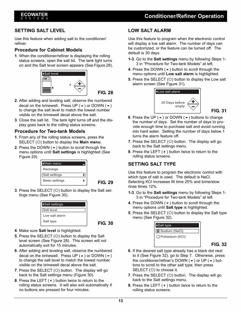
LOW SALT ALARMUse this feature to program when the electronic controlwill display a low salt alarm. The number of days canbe customized, or the feature can be turned off. Thedefault is 30 days.1-3. Go to the Salt settings menu by following Steps 1-
3 in “Procedure for Two-tank Models” at left.4. Press the DOWN (6) button to scroll through themenu options until Low salt alarm is highlighted.
5. Press the SELECT (¡) button to display the Low saltalarm screen (See Figure 31).
FIG. 28
6. Press the UP (5) or DOWN (6) buttons to changethe number of days. Set the number of days to pro-vide enough time to purchase salt and avoid runninginto hard water. Setting the number of days below 1turns the alarm feature off.
7. Press the SELECT (¡) button. The display will goback to the Salt settings menu.
8. Press the LEFT (3) button twice to return to therolling status screens.
SETTING SALT TYPEUse this feature to program the electronic control withwhich type of salt is used. The default is NaCl.Selecting KCl increases fill time 25% and brine/slowrinse times 12%.1-3. Go to the Salt settings menu by following Steps 1-
3 in “Procedure for Two-tank Models” at left.4. Press the DOWN (6) button to scroll through themenu options until Salt type is highlighted.
5. Press the SELECT (¡) button to display the Salt typemenu (See Figure 32).
FIG. 31
FIG. 326. If the desired salt type already has a black dot nextto it (See Figure 32), go to Step 7. Otherwise, pressthe conditioner/refiner’s DOWN (6) or UP (5) but-tons to scroll to the other salt type, then pressSELECT (¡) to choose it.
7. Press the SELECT (¡) button. The display will goback to the Salt settings menu.
8. Press the LEFT (3) button twice to return to therolling status screens.
SETTING SALT LEVELUse this feature when adding salt to the conditioner/refiner.Procedure for Cabinet Models1. When the conditioner/refiner is displaying the rollingstatus screens, open the salt lid. The tank light turnson and the Salt level screen appears (See Figure 28).
2. After adding and leveling salt, observe the numbereddecal on the brinewell. Press UP (5) or DOWN (6)to change the salt level to match the lowest numbervisible on the brinewell decal above the salt.
3. Close the salt lid. The tank light turns off and the dis-play goes back to the rolling status screens.
Procedure for Two-tank Models1. From any of the rolling status screens, press theSELECT (¡) button to display the Main menu.
2. Press the DOWN (6) button to scroll through themenu options until Salt settings is highlighted (SeeFigure 29).
3. Press the SELECT (¡) button to display the Salt set-tings menu (See Figure 30).
FIG. 29
FIG. 304. Make sure Salt level is highlighted.5. Press the SELECT (¡) button to display the Saltlevel screen (See Figure 28). This screen will notautomatically exit for 15 minutes.
6. After adding and leveling salt, observe the numbereddecal on the brinewell. Press UP (5) or DOWN (6)to change the salt level to match the lowest numbervisible on the brinewell decal above the salt.
7. Press the SELECT (¡) button. The display will goback to the Salt settings menu (Figure 30).
8. Press the LEFT (3) button twice to return to therolling status screens. It will also exit automatically ifno buttons are pressed for four minutes.
ECOWATERS Y S T E M S Conditioner/Refiner Operation

14
FIG. 34
2. Make sure Recharge is highlighted (See Figure 33).3. Press the SELECT (¡) button to display theRecharge menu (See Figure 34).
FIG. 33
4. If the desired option already has a black dot next to it(See Figure 34), go to Step 5. Otherwise, press theDOWN (6) or UP (5) buttons to scroll to the desiredoption, then press SELECT (¡) to choose it.=Automatic cancels a manually scheduled recharge(if it has not already begun) and lets the electroniccontrol determine when to recharge next.=Recharge now begins a recharge immediatelyafter the SELECT (¡) button is pushed again in Step5.=Schedule sets a recharge to begin at the presetrecharge time (set according to the instructions onPage 15).
5. Press the SELECT (¡) button. If Recharge now isselected, the display immediately goes to theRecharge status screen (See Figure 35). IfAutomatic or Schedule are selected, the displaygoes back to the Main menu (Figure 33).
SETTING THE CURRENT TIMEWhen the conditioner/refiner’s electronic control is firstpowered up, a “wizard” screen prompts you to set thecurrent time (See Page 9). To change the time at alater date, such as after a long power loss:1. From any of the rolling status screens, press theSELECT (¡) button to display the Main menu.
2. Press the DOWN (6) button to scroll through themenu options until Basic settings is highlighted(See Figure 36).
3. Press the SELECT (¡) button to display the Basicsettings menu (See Figure 37).
FIG. 36
FIG. 374. Make sure Current time is highlighted.5. Press the SELECT (¡) button to display the Currenttime screen (See Figure 38).
6. Press the UP (5) or DOWN (6) buttons to changethe time. Hold the button down to rapidly advance.Be sure that AM or PM is correct (unless condition-er/refiner is set for a 24-hour clock).
7. Press the SELECT (¡) button. The display will goback to the Basic settings menu (Figure 37).
8. Press the LEFT (3) button twice to return to therolling status screens.
FIG. 38
FIG. 356. Press the LEFT (3) button (twice from the Rechargestatus screen) to return to the rolling status screens.
ECOWATERS Y S T E M S Conditioner/Refiner Operation
RECHARGING THE CONDITIONER/REFINERThis feature may be used to assure an adequate supplyof conditioned water at times of unusually high wateruse. For example, if you have guests and the “Wateravailable” screen (See Page 18) is at or below 50%,you could deplete conditioned water capacity before thenext automatic recharge. Initiating a manual rechargewill restore 100% conditioned water capacity after com-plete.1. From any of the rolling status screens, press theSELECT (¡) button to display the Main menu.

15
SETTING RECHARGE TIMEWhen the conditioner/refiner’s electronic control is firstpowered up, the default time for starting an automaticrecharge is 2:00 a.m. This is a good time in mosthouseholds because water is not being used. Tochange this time:1. From any of the rolling status screens, press theSELECT (¡) button to display the Main menu.
2. Press the DOWN (6) button to scroll through themenu options until Basic settings is highlighted(See Figure 39).
FIG. 40
3. Press the SELECT (¡) button to display the Basicsettings menu (See Figure 40).
FIG. 41
FIG. 39
4. Press the DOWN (6) button to scroll through themenu options until Recharge time is highlighted.
5. Press the SELECT (¡) button to display theRecharge time screen (See Figure 41).
6. Press the UP (5) or DOWN (6) buttons to changethe recharge time in 1 hour increments. Hold thebutton down to rapidly advance. Be sure that AM orPM is correct (unless conditioner/refiner is set for a24-hour clock).
7. Press the SELECT (¡) button. The display will goback to the Basic settings menu (Figure 40).
8. Press the LEFT (3) button twice to return to therolling status screens.
7. Press the SELECT (¡) button. The display will goback to the Basic settings menu.
8. Press the LEFT (3) button twice to return to therolling status screens.
SETTING IRON LEVELWhen the conditioner/refiner’s electronic control is firstpowered up, a “wizard” screen prompts you to enteryour water’s iron level (See Page 9). The conversion is3 grains per ppm of clear water iron. To change:1-3. Go to the Basic settings menu by following Steps
1-3 in “Setting Recharge Time” at left.4. Press the DOWN (6) button to scroll through themenu options until Iron level is highlighted.
5. Press the SELECT (¡) button to display the Ironlevel screen (See Figure 43).
FIG. 436. Press the UP (5) or DOWN (6) buttons to set thevalue for iron in your water. Hold the button down torapidly advance.
7. Press the SELECT (¡) button. The display will goback to the Basic settings menu.
8. Press the LEFT (3) button twice to return to therolling status screens.
SETTING HARDNESSWhen the conditioner/refiner’s electronic control is firstpowered up, a “wizard” screen prompts you to enteryour water’s hardness (See Page 9). To change it:1-3. Go to the Basic settings menu by following Steps
1-3 in “Setting Recharge Time” at left.4. Press the DOWN (6) button to scroll through themenu options until Hardness is highlighted.
5. Press the SELECT (¡) button to display theHardness screen (See Figure 42).
FIG. 42
ECOWATERS Y S T E M S Conditioner/Refiner Operation
NOTE: Do not increase the hardness setting tocompensate for iron in your water. Theelectronic control compensates automaticallyafter you set the iron level, below.
6. Press the UP (5) or DOWN (6) buttons to set thevalue for your water’s hardness. Hold the buttondown to rapidly advance.

16
MODIFYING ROLLING SCREENSDuring normal conditioner/refiner operation, four statusscreens are shown in sequence (See “Conditioner/Refiner Status Screens” on Page 10). When the condi-tioner/refiner’s electronic control is first powered up, thedefault is to show all four. You can turn on/off individualscreens*:1. From any of the rolling status screens, press theSELECT (¡) button to display the Main menu.
2. Press the DOWN (6) button to scroll through themenu options until Basic settings is highlighted(See Figure 44).
3. Press the SELECT (¡) button to display the Basicsettings menu (See Figure 45).
FIG. 44
FIG. 454. Press the DOWN (6) button to scroll through themenu options until Rolling screens is highlighted.
5. Press the SELECT (¡) button to display the Rollingscreens menu (See Figure 46).
FIG. 466. Press the DOWN (6) or UP (5) buttons to scrollthrough the list. Items with a black square next tothem will be displayed during normal operation.
7. To un-select a screen, make sure its name is high-lighted in a box. Then press the SELECT (¡) button.The black square will disappear. Pressing SELECT(¡) again makes the black square reappear and re-selects the highlighted item. At least one screenmust be selected/highlighted.
8. When selections are complete, exit this menu bypressing the LEFT (3) button. The display will goback to the Basic settings menu (Figure 45).
9. Press the LEFT (3) button twice to return to therolling status screens.*This does not include service reminders, errors, alerts orRecharge status screens.
SETTING THE LANGUAGEWhen the conditioner/refiner’s electronic control is firstpowered up, a “wizard” screen prompts you to set thelanguage (See Page 9). Language is set independentlyon the conditioner/refiner and remote (See Page 28 toset the remote’s language). To change the conditioner/refiner’s language:1. From any of the rolling status screens, press theSELECT (¡) button to display the Main menu.
2. Press the DOWN (6) button to scroll through themenu options until User preferences is highlighted(See Figure 47).
4. Make sure Language is highlighted.5. Press the SELECT (¡) button to display theLanguage menu (See Figure 49).
FIG. 47
FIG. 48
3. Press the SELECT (¡) button to display the Userpreferences menu (See Figure 48).
FIG. 496. If the desired language already has a black dot nextto it (See Figure 49), go to Step 7. Otherwise, pressthe DOWN (6) or UP (5) buttons to scroll to thedesired language, then press SELECT (¡) to chooseit. The choices are: English, Spanish, French, Italian,German, Dutch, Polish, Russian, Hungarian, Turkish,Lithuanian, Greek or Romanian.
7. Press the SELECT (¡) button. The display will goback to the User preferences menu (Figure 48).
8. Press the LEFT (3) button twice to return to therolling status screens.TO SET THE CONDITIONER/REFINER TO ENG-LISH IF ANOTHER LANGUAGE IS DISPLAYED:From the rolling status screens, press SELECT (¡).Press DOWN (6) three times, then press SELECT(¡) twice. Press UP (5) to scroll to English at thetop of the list, then press SELECT (¡) twice. PressLEFT (3) twice to exit all menus.
ECOWATERS Y S T E M S Conditioner/Refiner Operation

17
SETTING TIME FORMATUse this feature to select a 12-hour (AM/PM) or 24-hourclock.1. From any of the rolling status screens, press theSELECT (¡) button to display the Main menu.
2. Press the DOWN (6) button to scroll through themenu options until User preferences is highlighted.
3. Press the SELECT (¡) button to display the Userpreferences menu.
4. Press the DOWN (6) button to scroll through themenu options until Time format is highlighted.
5. Press the SELECT (¡) button to display the Timeformat menu (See Figure 50).
FIG. 506. If the desired time format already has a black dotnext to it (See Figure 50), go to Step 7. Otherwise,press the DOWN (6) or UP (5) buttons to scroll tothe other time format, then press SELECT (¡) tochoose it.
7. Press the SELECT (¡) button. The display will goback to the User preferences menu.
8. Press the LEFT (3) button twice to return to therolling status screens.
SETTING VOLUME UNITSUse this feature to select gallons or liters as volumeunits.1-3. Go to the User preferences menu by following
Steps 1-3 in “Setting Time Format” above.4. Press the DOWN (6) button to scroll through themenu options until Volume units is highlighted.
5. Press the SELECT (¡) button to display the Volumeunits menu (See Figure 51).
FIG. 516. If the desired volume unit already has a black dotnext to it (See Figure 51), go to Step 7. Otherwise,press the DOWN (6) or UP (5) buttons to scroll tothe other volume unit, then press SELECT (¡) tochoose it.
7. Press the SELECT (¡) button. The display will goback to the User preferences menu.
8. Press the LEFT (3) button twice to return to therolling status screens.
SETTING HARDNESS UNITSUse this feature to select grains or parts per million(ppm) as hardness units.1. From any of the rolling status screens, press theSELECT (¡) button to display the Main menu.
2. Press the DOWN (6) button to scroll through themenu options until User preferences is highlighted.
3. Press the SELECT (¡) button to display the Userpreferences menu.
4. Press the DOWN (6) button to scroll through themenu options until Hardness units is highlighted.
5. Press the SELECT (¡) button to display theHardness units menu (See Figure 52).
FIG. 526. If the desired hardness unit already has a black dotnext to it (See Figure 52), go to Step 7. Otherwise,press the DOWN (6) or UP (5) buttons to scroll tothe other hardness unit, then press SELECT (¡) tochoose it.
7. Press the SELECT (¡) button. The display will goback to the User preferences menu.
8. Press the LEFT (3) button twice to return to therolling status screens.
SETTING WEIGHT UNITSUse this feature to select pounds or kilograms asweight units.1-3. Go to the User preferences menu by following
Steps 1-3 in “Setting Hardness Units” above.4. Press the DOWN (6) button to scroll through themenu options until Weight units is highlighted.
5. Press the SELECT (¡) button to display the Weightunits menu (See Figure 53).
FIG. 536. If the desired weight unit already has a black dot nextto it (See Figure 53), go to Step 7. Otherwise, pressthe DOWN (6) or UP (5) buttons to scroll to theother weight unit, then press SELECT (¡) to chooseit.
7. Press the SELECT (¡) button. The display will goback to the User preferences menu.
8. Press the LEFT (3) button twice to return to therolling status screens.
ECOWATERS Y S T E M S Conditioner/Refiner Operation

18
SYSTEM INFORMATIONUse these features to look up the following informationabout the conditioner/refiner and its operations:
=Model information (model number and softwareversion)
=Water available (conditioned water ready for use)=Daily average water used=Water used today=Total water used (explained in Step 6, below)=Current water flow=Days powered up=Last recharge=Total recharges
To display one of these screens:1. From any of the rolling status screens, press theSELECT (¡) button to display the Main menu.
2. Press the DOWN (6) button to scroll through themenu options until System information is highlight-ed (See Figure 54).
FIG. 54
FIG. 55
3. Press the SELECT (¡) button to display the Systeminformation menu (See Figure 55).
4. Press the DOWN (6) button to scroll through themenu options until the desired option is highlighted(See list at the top of this column).
5. Press the SELECT (¡) button to display the desiredinformation screen (See Figures 56-64).
6. The Total water used screen (See Figure 60) showsthe volume of water used since it was last reset (itworks like the trip odometer in a car). To reset thevalue to 0, press the RIGHT (4) button while thisscreen is displayed.
7. When finished viewing an information screen, pressthe SELECT (¡) button. The display will go back tothe System information menu (Figure 55). It will alsoexit automatically if no buttons are pressed for fourminutes.
8. Press the LEFT (3) button twice to return to therolling status screens.
FIG. 56
FIG. 57
FIG. 58
FIG. 59
FIG. 60
FIG. 61
FIG. 62
FIG. 63
FIG. 64
ECOWATERS Y S T E M S Conditioner/Refiner Operation

19
CYCLE TIMESUse these features to change the following conditioner/refiner operations:
=Backwash time=Second backwash (On/Off)=Second backwash time=Fast rinse time
To display these screens:1. From any of the rolling status screens, press theSELECT (¡) button to display the Main menu.
2. Press the DOWN (6) button to scroll through themenu options until Advanced settings is highlighted(See Figure 65).
FIG. 67
FIG. 68
6. Press the DOWN (6) button to scroll through themenu options until the desired option is highlighted(See list at the top of this column).
7. Press the SELECT (¡) button to display the desiredinformation screen (See Figures 68-71).
8. See the right column on this page for specificinstructions on each cycle time screen.
9. Press the SELECT (¡) button. The display will goback to the Cycle times menu (Figure 67).
10. Press the LEFT (3) button three times to return tothe rolling status screens.
8a. Backwash time: Press the UP (5) or DOWN(6) buttons to change the backwash time.Hold the button down to rapidly advance. Thebackwash time can be set from 1 to 30 min-utes* (See Figure 68).
FIG. 664. Make sure Cycle times is highlighted.5. Press the SELECT (¡) button to display the Cycletimes menu (See Figure 67).
FIG. 653. Press the SELECT (¡) button to display theAdvanced settings menu (See Figure 66).
FIG. 69
8b. Second backwash (On/Off): If the desiredoption already has a black dot next to it (SeeFigure 69), go to Step 9. Otherwise, press theDOWN (6) or UP (5) buttons to scroll to theother option, then press SELECT (¡) to chooseit. Setting this feature On adds a second back-wash and rinse at the beginning of the rechargecycle. Default is Off. Set this feature On if yourwater supply contains a lot of sediment or iron.
FIG. 70
8c. Second backwash time: Press the UP (5) orDOWN (6) buttons to change the second back-wash time. Hold the button down to rapidlyadvance. The time can be set from 1 to 30minutes (See Figure 70).
FIG. 71
8d. Fast rinse time: Press the UP (5) or DOWN(6) buttons to change the fast rinse time. Holdthe button down to rapidly advance. The fastrinse time can be set from 1 to 30 minutes*(See Figure 71).
ECOWATERS Y S T E M S Conditioner/Refiner Operation
*Reducing the backwash and fast rinse times below aconditioner/refiner model’s default settings can result insalty water after recharges.

20
SPECIAL FEATURESUse these features to change the following operations:
=Efficiency mode=Maximum days between recharges=Auxiliary control (described on Page 21)=Chemical feed volume* (described on Page 21)=Chemical feed timer* (described on Page 21)=97% feature=Service reminder (described on Page 22)
To display one these screens:1. From any of the rolling status screens, press theSELECT (¡) button to display the Main menu.
2. Press the DOWN (6) button to scroll through themenu options until Advanced settings is highlighted(See Figure 72).
FIG. 734. Press the DOWN (6) button to scroll through themenu options until Special features is highlighted.
5. Press the SELECT (¡) button to display the Specialfeatures menu (See Figure 74).
FIG. 723. Press the SELECT (¡) button to display theAdvanced settings menu (See Figure 73).
FIG. 746. Press the DOWN (6) button to scroll through themenu options until the desired option is highlighted(See list at the top of this column).
7. Press the SELECT (¡) button to display the desiredinformation screen (See Figures 75-77).
8. See the right column on this page for specificinstructions on each cycle time screen.
9. Press the SELECT (¡) button. The display will goback to the Special features menu (Figure 74).
10. Press the LEFT (3) button three times to return tothe rolling status screens.
*Only displayed if Auxiliary control is set to Chemical feed.
FIG. 75
FIG. 76
FIG. 77
8a. Efficiency mode: If the desired efficiencymode already has a black dot next to it (SeeFigure 75), go to Step 9. Otherwise, press theDOWN (6) or UP (5) buttons to scroll to thedesired efficiency mode, then press SELECT(¡) to choose it.=Salt efficient limits available salt doses tomaintain 4000 grains/lb. of salt efficiency.Units may recharge more frequently.=Auto adjusting is the default. It automati-cally adjusts salt doses to target a 3-4 dayinterval between recharges. Recommended.=High capacity is for applications where verylow “bleed” (less than 1.5 ppm) of hardnesscan be tolerated. Such applications includewater for boilers. This setting will consumehigher quantities of salt.
8b. Maximum days between recharges: Pressthe UP (5) or DOWN (6) buttons to changethe number of days (See Figure 76). The fea-ture can be set from 1 to 15 days. Setting thenumber of days below 1 turns the feature offand defaults to automatic control of recharging.
8c. 97% feature: If the desired option already hasa black dot next to it (See Figure 77), go toStep 9. Otherwise, press the DOWN (6) orUP (5) buttons to scroll to the other option,then press SELECT (¡) to choose it. If thisfeature is On, the conditioner/refiner will auto-matically recharge when 97% of capacity isused, at any time of day. Default is Off.
ECOWATERS Y S T E M S Conditioner/Refiner Operation
NOTE: California regulations require the effi-ciency mode be set to Salt efficient forunits installed in the state of California.

21
FIG. 80
FIG. 81
FIG. 78
AUXILIARY CONTROLThe electronic control has an auxiliary output which cancontrol external devices in a water treatment system.The signal is 24V AC, current draw 800 mA maximum.The Auxiliary Output terminals are located on the elec-tronic control board (See Schematic on Page 39).For more details on the use of auxiliary controlledequipment in water treatment systems, consult theEcoWater Systems “Problem Water Guide.”To select an auxiliary control mode:1. From any of the rolling status screens, press theSELECT (¡) button to display the Main menu.
2. Press the DOWN (6) button to scroll through themenu options until Advanced settings is highlighted.
3. Press the SELECT (¡) button to display theAdvanced settings menu.
4. Press the DOWN (6) button to scroll through themenu options until Special features is highlighted.
5. Press the SELECT (¡) button to display the Specialfeatures menu (See Figure 78).
6. Press the DOWN (6) button to scroll through themenu options until Auxiliary control is highlighted.
7. Press the SELECT (¡) button to display the Auxiliarycontrol menu (See Figure 79).
8. If the desired option already has a black dot next to it(See Figure 79), go to Step 9. Otherwise, press theDOWN (6) or UP (5) buttons to scroll to the desiredoption, then press SELECT (¡) to choose it.=Off is the default.=Chlorine can be used to drive a chlorine generator,which produces chlorine, as brine water passesthrough it, to sanitize the resin during recharges.
=Bypass turns 24V AC on during the entire regener-ation cycle (when the conditioner/refiner’s valve isin bypass and hard water is being supplied to thehouse).
=Chemical feed can be used to run a chemical feedpump. If chosen, the chemical feed volume andtimer must be set, as detailed at right)
=Water use turns 24V AC on when the conditioner/refiner’s turbine indicates water flow. Could drivean air pump for iron or sulfur oxidation.
9. Press the SELECT (¡) button. The display will goback to the Special features menu (Figure 78).
10. Press the LEFT (3) button three times to return tothe rolling status screens.
FIG. 79CHEMICAL FEEDIf the auxiliary control mode has been set to Chemicalfeed, as described in the previous section, two addition-al lines (Chemical feed volume and Chemical feedtimer) will appear on the Special features menu.To set these values:1. From any of the rolling status screens, press theSELECT (¡) button to display the Main menu.
2. Press the DOWN (6) button to scroll through themenu options until Advanced settings is highlighted.
3. Press the SELECT (¡) button to display theAdvanced settings menu.
4. Press the DOWN (6) button to scroll through themenu options until Special features is highlighted.
5. Press the SELECT (¡) button to display the Specialfeatures menu (See Figure 78).
6. Press the DOWN (6) button to scroll through themenu options until Chemical feed volume orChemical feed timer is highlighted.
7. Press the SELECT (¡) button to display theChemical feed volume or Chemical feed timer menu(See Figures 80 & 81).
8. Press the UP (5) or DOWN (6) buttons to changethe value. Hold the button down to rapidly advance.=Chemical feed volume is the amount of waterwhich will pass through the conditioner/refinerbetween each activation of the chemical feedequipment.
=Chemical feed timer is how long the output to thechemical feed equipment is energized each time itis activated.
9. Press the SELECT (¡) button. The display will goback to the Special features menu (Figure 78).
10. Press the LEFT (3) button three times to return tothe rolling status screens.
ECOWATERS Y S T E M S Conditioner/Refiner Operation

22
FIG. 83
FIG. 84
SERVICE REMINDER (set / reset)Use this feature to program the number of months (upto 24) before a “Service overdue” message will appearinstead of the rolling status screens (See Figure 82).
8. Press the UP (5) or DOWN (6) buttons to set thenumber of months until the service reminderappears. Repeatedly pressing the DOWN (6) but-ton until the display reads “Off” turns this feature offand zeros the number of months and days.
9. Press the SELECT (¡) button. The display will goback to the Special features menu (Figure 83).
10. Press the LEFT (3) button three times to return tothe rolling status screens.
6. Press the DOWN (6) button to scroll through themenu options until Service reminder is highlighted.
7. Press the SELECT (¡) button to display the Servicereminder screen (See Figure 84).
This message also appears on the remote. This will bea reminder to call your dealer for service. Once pro-grammed, this feature displays the number of monthsand days left until the service reminder.Once the “Service overdue” message has appeared,dealers performing service clear it by setting the num-ber of months until the next service reminder. Set orreset the service reminder as follows:1. From any of the rolling status screens, press theSELECT (¡) button to display the Main menu.
2. Press the DOWN (6) button to scroll through themenu options until Advanced settings is highlighted.
3. Press the SELECT (¡) button to display theAdvanced settings menu.
4. Press the DOWN (6) button to scroll through themenu options until Special features is highlighted.
5. Press the SELECT (¡) button to display the Specialfeatures menu (See Figure 83).
FIG. 82
SEND E.A.S.E. MESSAGEWith E.A.S.E. (Electronic Automated ServiceEvaluation), a homeowner or service technician cantransmit operational data via a telephone for diagnosticpurposes. Ask your participating EcoWater Systemsdealer for more information.To send an E.A.S.E. message:1. From any of the rolling status screens, press theSELECT (¡) button to display the Main menu.
2. Press the DOWN (6) button to scroll through themenu options until Advanced settings is highlighted.
3. Press the SELECT (¡) button to display theAdvanced settings menu (See Figure 85).
FIG. 86
FIG. 87
6. Make sure Send EASE message is highlighted.7. With the phone ready, press the SELECT (¡) buttonto display the Send EASE message screen andbegin transmission.
8. Hold the phone’s receiver an inch or two above theE.A.S.E. port on the conditioner/refiner’s faceplate(See Figure 7 on Page 9). Maintain the receiversteadily in this position during the entire transmis-sion.
9. A bar is displayed showing the transmission’sprogress (See Figure 87). Once completed, theTroubleshooting screen immediately reappears(Figure 86).
10. Press the LEFT (3) button three times to return tothe rolling status screens.
FIG. 854. Press the DOWN (6) button to scroll through themenu options until Troubleshooting is highlighted.
5. Press the SELECT (¡) button to display theTroubleshooting menu (See Figure 86).
ECOWATERS Y S T E M S Conditioner/Refiner Operation

23
DIAGNOSTICSThis feature allows a service technician to check theoperating state of individual components in the condi-tioner/refiner (e.g. valve position) to troubleshoot prob-lems. If an error code is displayed in place of therolling status screens, call your dealer for service.To view the Diagnostics screen:1. If an error code is displayed, skip Steps 2-7 and godirectly to Step 8.
2. To display the Diagnostics screen from any of therolling status screens (when an error code is not dis-played), press the SELECT (¡) button to display theMain menu.
3. Press the DOWN (6) button to scroll through themenu options until Advanced settings is highlighted.
4. Press the SELECT (¡) button to display theAdvanced settings menu.
5. Press the DOWN (6) button to scroll through themenu options until Troubleshooting is highlighted.
6. Press the SELECT (¡) button to display theTroubleshooting menu (See Figure 88).
SETUP CHANGESThis feature allows a service technician to repeat thesetup procedure (See Page 9) or restore the condition-er/refiner’s default operating values.1. From any of the rolling status screens, press theSELECT (¡) button to display the Main menu.
2. Press the DOWN (6) button to scroll through themenu options until Advanced settings is highlighted.
3. Press the SELECT (¡) button to display theAdvanced settings menu.
4. Press the DOWN (6) button to scroll through themenu options until Troubleshooting is highlighted.
5. Press the SELECT (¡) button to display theTroubleshooting menu (See Figure 88).
6. Press the DOWN (6) button to scroll through themenu options until Setup changes is highlighted.
7. Press the SELECT (¡) button to display the Setupchanges menu (See Figure 90).
FIG. 887. Press the DOWN (6) button to scroll through themenu options until Diagnostics is highlighted.
8. Press the SELECT (¡) button to display theDiagnostics screen (See Figure 89).
FIG. 899. Press the DOWN (6) or UP (5) buttons to scrollthrough the list. The following items are displayed:=Time (current)=Position time (counts down the time remaining inthe current valve position)
=Current position (of the valve: service, fill, brine,backwash, fast rinse or moving)
=Requested position (of the valve)=Motor state (on or off)=Valve position switch (open or closed)=Turbine count (if changing, indicates water flow)=Tank light switch (open or closed)=RF module (detected or not)=Error code (call for service if a number is dis-played)
continued
10. When finished viewing the Diagnostics screen,press the SELECT (¡) button. The display will goback to the Troubleshooting menu.
11. Press the LEFT (3) button three times to return tothe rolling status screens (or error code screen if anerror condition exists).
FIG. 908. If the desired option already has a black dot next to it(See Figure 90), go to Step 9. Otherwise, press theDOWN (6) or UP (5) buttons to scroll to the desiredoption, then press SELECT (¡) to choose it.=Redo setup allows you to select a different modelcode (intended to be used for upgrades or retrofitsof existing conditioner/refiners). Model codes arelisted on Page 40.
=Restore defaults will reset all customizable set-tings to their default values and take you throughthe “wizard” screen setup procedure (See Page 9).
=Cancel will return to the Troubleshooting menu(Figure 88).
9. Press the SELECT (¡) button.
ECOWATERS Y S T E M S Conditioner/Refiner Operation

24
UNPACKINGThe EcoWater Systems HydroLink™ remote is shippedfrom the factory in one carton. Thoroughly check forpossible shipping damage and parts loss. Also noteany damage to the shipping carton. Notify the trans-portation company if damage is present. EcoWaterSystems is not responsible for in-transit damages.Remove and discard (RECYCLE) all packing materials.
ITEMS INCLUDED WITH SHIPMENT
FIG. 91Remote (including
Battery Cover)
Support 3 Batteries(AA size)
INSTALLING BATTERIES1. Remove the battery cover from the back of theremote.
2. Install three (3) AA size batteries, making sure thatthey are oriented to match the � and – markingsinside the battery compartment (See Figure 92).
3. Snap the battery cover back in place.
FIG. 92
FIG. 94
INSTALLING THE SUPPORTThe EcoWater Systems HydroLink™ remote is shippedwith a teardrop-shaped support to hold the unit at anangle when placed on a horizontal surface.1. Snap one of the support’s two tabs into the rectangu-lar slot on the back of the remote’s case (See Figure93).
OPTIONAL WALL MOUNTINGThe EcoWater Systems HydroLink™ remote (withoutthe support) may also be mounted on a wall. If thisoption is desired, install two fasteners (not included) ata convenient height, spaced 6-1/8” (156 mm) apart(See Figure 95).
FIG. 95
FIG. 93
Supporthas 2 tabsSlot inbattery cover
BatteryCover
3 Batteries(AA size)
6-1/8”(156 mm)
2. The angle may be adjusted by reorienting the sup-port in the battery cover (See Figure 94).
ECOWATERS Y S T E M S Remote Unpacking & Installation
NOTE: When replacing batteries in a remote that waspreviously connected to a conditioner/refiner, itis not necessary to reconnect the remote andconditioner/refiner.

25
HYDROLINK™ REMOTEThe EcoWater Systems HydroLink™ remote is part of awireless system which monitors multiple water treat-ment devices in a home. These water treatmentdevices include water conditioner/refiner(s) and drinkingwater filter(s) equipped to communicate with this type ofsystem (See Figure 96). The remote displays, in a con-venient, central location, useful operating information.Once devices capable of communicating with the sys-tem have been added to the remote (See “Adding aDevice” on Page 26), the remote’s normal operatingmode displays a sequence of screens showing the sta-tus of each device in the system (See Figure 97), andany active alerts, such as “Low salt.”In addition to monitoring water treatment devices, theremote can also control some water conditioner/refineroperations, such as initiating a manual recharge.
HYDROLINK™ COMMUNICATION SYSTEMThe devices in the system exchange information in aloosely coupled network. AC powered devices, such asconditioner/refiners, listen for new data all the time andact as data hubs. Battery powered devices like theremote check for information at regular intervals.Battery powered devices like drinking water systems donot communicate directly with each other or the remote,but pass along information through AC powereddevices. Up to 4 devices may be added to one remote,including no more than 3 AC powered devices. An ACpowered device with a transmitter must be part of anynetwork (usually a water conditioner/refiner).It is not necessary for every device in a network to be inradio range of all others. Information one device com-municates to any other device will be passed along (likegossip) to all devices in the network.
Remote
System 1Water
Drinking
Drinking
System 2Water
Conditioner/Water
Refiner
FIG. 96
FIG. 97
System 1Water
statusSystem 2
Water
status
Active Alerts(if any)
Drinking Drinking
RefinerConditioner/
status
Water
NAVIGATING THE SCREENSWhen the remote is powered up (by installing the bat-teries), a logo will briefly appear in the display. Once adevice has been added, as shown in the procedure onPage 26, the display will automatically cycle betweenscreens showing the status of water treatment devicescommunicating with the remote. To manually go to thenext screen in the sequence, press the LEFT (3) orRIGHT (4) buttons.
FIG. 98
ACTIVE ALERTSThe status screens described above will not be dis-played in a rolling sequence when one of the followingactive alert messages is displayed:
=Low salt (See Page 33)=Time lost (Set the conditioner/refiner’s clock, asdescribed on Page 14)
=Service overdue (See Page 22)=Error code (Contact your dealer for service)
MANUALLY REFRESHING THE DATAIf there has been no button activity for 30 seconds,pressing any button will refresh the data being dis-played. Normally each data element refreshes at amuch slower rate to conserve battery life.
ECOWATERS Y S T E M S Remote Introduction
Some screens have more information than can beshown at one time (for example, the conditioner/refinerstatus display shown in Figure 98). A down arrow (6)in the lower right corner indicates that there is moreinformation below. Use the DOWN (6) button to scrollthrough the additional lines.

26
AlertTM
FIG. 99
DisplayLEFTButton
RIGHTButton
UPButton
DOWNButton
AlertLED
SELECTButton
ADDING A DEVICETo initiate communication between the remote and adevice such as a conditioner/refiner, it is necessary toadd the device to the remote by doing the following:1. If no device has been added to the remote, the menushown in Figure 100 is displayed instead of statusscreens. In this case, skip to step 2. Otherwise, ifstatus screens are shown, press the remote’sSELECT (¡) button to display a Menu screen (SeeFigure 100).
2. Press the DOWN (6) button to scroll through themenu options until Add new device is highlighted ina box (See Figure 101).
3. Press the SELECT (¡) button, and the screen shownin Figure 102 appears. The remote waits two min-utes for the device to be activated (following theinstructions in that device’s manual). For completeinstructions on adding the conditioner/refiner, refer to“Connecting to Remote” on Page 11 of this manual.
4. When the remote detects a signal from the device,the display will change to show that it has beenadded to the remote (See Figure 103). If anothermessage appears instead, indicating the device wasnot added successfully, press the LEFT (3) button toreturn to the screen in Figure 101. Repeat Step 3. Ifthis does not work, contact your dealer for service.
FIG. 100
FIG. 101
FIG. 102
FIG. 1035. To exit this screen, press the LEFT (3) button orwait 30 seconds for it to exit automatically.
REMOTE MENUSStartup MenuBefore any devices have been added to the remote, thefollowing menu is displayed:=Display options
=Set language (See Page 28)=Network options
=Add new device (See Page 26)Conditioner/Refiner MenuAfter the conditioner/refiner has been added, the re -mote will display a conditioner/refiner status screen asone of the rolling status screens. Pressing the remote’sSELECT (¡) button when the conditioner/ refiner statusscreen is displayed shows the following menu:=Remote Control
=Recharge (See Page 29)=Recharge time (See Page 29)
=Display options=Display data (See Page 30)=Display order (See Page 31)=Remote control data (See Page 31)=Rename device (See Page 32)=Set language (See Page 28)
=Network options=Add new device (See Page 26)=Delete current device (See Page 32)=RF signal strength (See Page 27)
Drinking Water Status MenuIf no drinking water system has been added, the remotewill display a drinking water status screen as one of therolling status screens. Pressing the remote’s SELECT(¡) button when the drinking water status screen is dis-played shows the following menu:=Display options
=Drinking water message (See Page 28)=Set language (See Page 28)
=Network options=Add new device (See Page 26)
ECOWATERS Y S T E M S Remote Operation
PhotoCell

27
FIG. 104
FIG. 105
FIG. 106
2. Press the remote’s SELECT (¡) button to display thedevice menu.
3. Press the DOWN (6) button to scroll through themenu options until RF signal strength is highlightedin a box (See Figure 105).
4. Press the SELECT (¡) button, and the screen shownin Figure 106 will appear. The more bars that arefilled in black, the stronger the signal. The signalstrength display updates every 15 seconds.
ECOWATERS Y S T E M S Remote Operation
5. To exit this screen, press the LEFT (3) button.
PHOTO CELLTo prolong battery life, the remote has a photo cellabove the display (See Figure 99). This cell triggersthe display to “go to sleep” (turn off) when the ambientlight level stays low for 10 minutes. The display willimmediately turn back on when the ambient light level isincreased.NOTE: The “Alert” LED (See Figure 99) will not “go to
sleep” if ambient light levels are low.
CHECKING RF SIGNAL STRENGTHDuring installation of a system, it is useful to check thestrength of the signal from a water treatment device.As described on Page 25 (HydroLink™ CommunicationSystem), the remote receives direct signals only fromAC powered devices, such as conditioner/refiners.Battery-powered devices like drinking water systemspass their information along indirectly, by way of the ACdevices. If you check the signal strength of a devicenot in direct communication with the remote, the displaywill show the strength of the “weakest link” in the chainof communication to the remote.Begin by checking the signal strength between the con-ditioner/refiner and the remote. If the signal is weak (2bars or less on the display shown in Figure 106), movethe remote to a different location to try improving thesignal strength.When adding additional devices, such as battery-oper-ated drinking water systems (RO), keep in mind that thesignal strength display shows the “weakest link” in thechain of communications. If the link between the ROand the conditioner/refiner is weak, move the RO (ifpossible) to a location closer to the conditioner/refineror remove metal objects between the two.
continued
To check the signal strength for a particular device:1. Press the remote’s LEFT (3) or RIGHT (4) buttonsto manually advance to the status screen for thedevice you want to check. The device name willshow in the header. (See Figure 104).

28
SETTING THE LANGUAGELanguage is set independently on the remote and con-ditioner/refiner (See Page 16 to set the conditioner/refiner’s language). Fewer languages are available onthe remote. To change the remote’s language:1. Press the remote’s SELECT (¡) button to display aMenu screen.
2. Press the DOWN (6) button to scroll through themenu options until Set language is highlighted in abox (See Figure 107). Press the SELECT (¡) button.
5. Press the DOWN (6) or UP (5) buttons to scrollthrough the list to the desired language, then pressSELECT (¡) to choose it.
6. Press the SELECT (¡) button. The display will goback to the menu shown in Figure 107, in the newlyset language.
7. To exit this menu, press the LEFT (3) button or wait30 seconds for it to exit automatically.
FIG. 107
FIG. 108
ECOWATERS Y S T E M S Remote Operation
TO SET THE REMOTE TO ENGLISHIF ANOTHER LANGUAGE IS DISPLAYED:
From the rolling status screens, press SELECT (¡).Press DOWN (6) to scroll through the list until theline immediately above the antenna ( ) symbolis highlighted (See Figure 109), then pressSELECT (¡). Press UP (5) to scroll to English atthe top of the list, then press SELECT (¡) twice.Press LEFT (3) to exit the menu.
3. Depending on which devices are added, you couldsee a message saying “This will delete all devices!Continue?” If so, you would need to add the devicesagain after changing the language. Press the RIGHT(4) button to continue (or skip to Step 4 if this mes-sage is not displayed).
4. The Set language menu is displayed (See Figure108). The current language has a black dot next to it.
FIG. 109
DRINKING WATER STATUS MESSAGEIf a communications-capable drinking water filtration(RO) system has been added to the remote, it will haveits own status screen displayed during normal opera-tion. Otherwise, a drinking water status screen will dis-play a message like the one shown in Figure 110.If the message displayed is not appropriate to your sys-tem, change it as follows:1. Press the remote’s LEFT (3) or RIGHT (4) buttonsto manually advance to the Drinking water statusscreen (See Figure 110).
4. Press the SELECT (¡) button to display the Drinkingwater message menu (See Figure 112).
5. The current message has a black dot next to it.Press the DOWN (6) or UP (5) buttons to scrollbetween the two messages, then press SELECT (¡)to choose one.
6. Press the SELECT (¡) button. The display will goback to the menu shown in Figure 111.
7. Press the LEFT (3) button to exit this menu, or wait30 seconds for it to exit automatically.
FIG. 111
FIG. 112
FIG. 1102. Press the remote’s SELECT (¡) button to display thedrinking water status menu (See Figure 111).
3. If necessary, press the DOWN (6) button to scrollthrough the menu options until Drinking water mes-sage is highlighted in a box (See Figure 111).
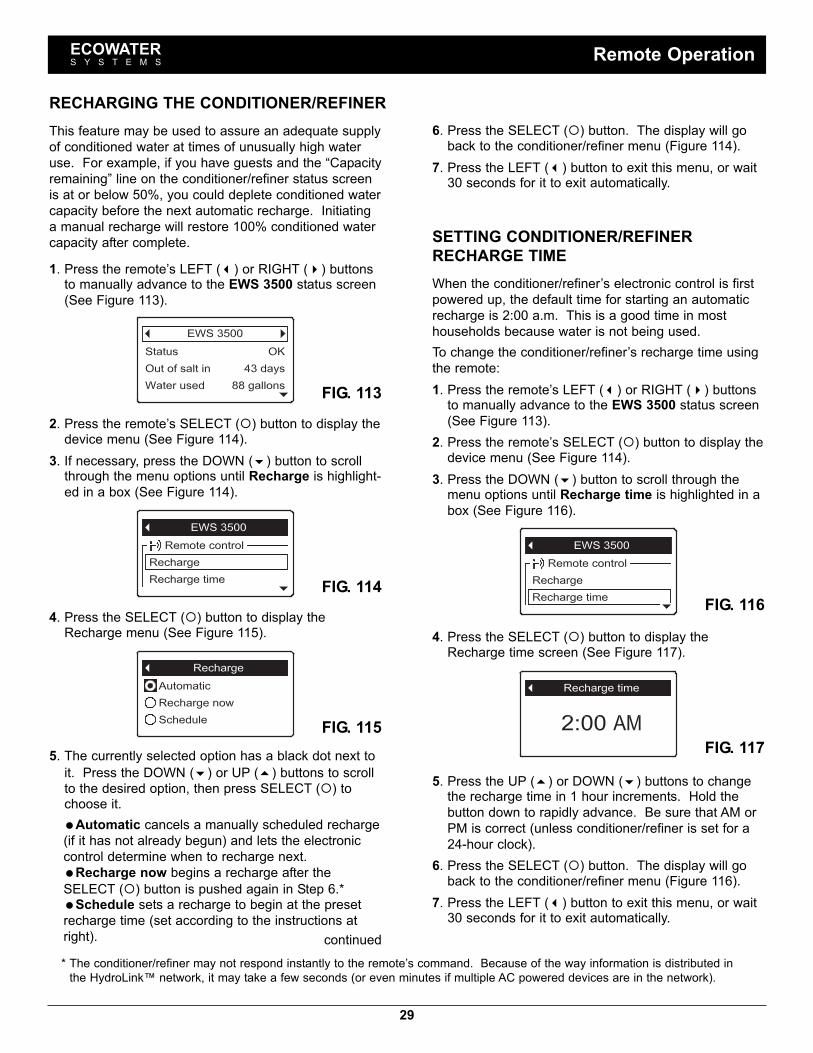
29
This feature may be used to assure an adequate supplyof conditioned water at times of unusually high wateruse. For example, if you have guests and the “Capacityremaining” line on the conditioner/refiner status screenis at or below 50%, you could deplete conditioned watercapacity before the next automatic recharge. Initiatinga manual recharge will restore 100% conditioned watercapacity after complete.1. Press the remote’s LEFT (3) or RIGHT (4) buttonsto manually advance to the EWS 3500 status screen(See Figure 113).
4. Press the SELECT (¡) button to display theRecharge menu (See Figure 115).
5. The currently selected option has a black dot next toit. Press the DOWN (6) or UP (5) buttons to scrollto the desired option, then press SELECT (¡) tochoose it.=Automatic cancels a manually scheduled recharge(if it has not already begun) and lets the electroniccontrol determine when to recharge next.=Recharge now begins a recharge after theSELECT (¡) button is pushed again in Step 6.*=Schedule sets a recharge to begin at the presetrecharge time (set according to the instructions atright).
FIG. 115
FIG. 114FIG. 116
FIG. 117
SETTING CONDITIONER/REFINERRECHARGE TIMEWhen the conditioner/refiner’s electronic control is firstpowered up, the default time for starting an automaticrecharge is 2:00 a.m. This is a good time in mosthouseholds because water is not being used.To change the conditioner/refiner’s recharge time usingthe remote:1. Press the remote’s LEFT (3) or RIGHT (4) buttonsto manually advance to the EWS 3500 status screen(See Figure 113).
2. Press the remote’s SELECT (¡) button to display thedevice menu (See Figure 114).
3. Press the DOWN (6) button to scroll through themenu options until Recharge time is highlighted in abox (See Figure 116).
4. Press the SELECT (¡) button to display theRecharge time screen (See Figure 117).
FIG. 1132. Press the remote’s SELECT (¡) button to display thedevice menu (See Figure 114).
3. If necessary, press the DOWN (6) button to scrollthrough the menu options until Recharge is highlight-ed in a box (See Figure 114).
6. Press the SELECT (¡) button. The display will goback to the conditioner/refiner menu (Figure 114).
7. Press the LEFT (3) button to exit this menu, or wait30 seconds for it to exit automatically.
* The conditioner/refiner may not respond instantly to the remote’s command. Because of the way information is distributed inthe HydroLink™ network, it may take a few seconds (or even minutes if multiple AC powered devices are in the network).
ECOWATERS Y S T E M S Remote Operation
5. Press the UP (5) or DOWN (6) buttons to changethe recharge time in 1 hour increments. Hold thebutton down to rapidly advance. Be sure that AM orPM is correct (unless conditioner/refiner is set for a24-hour clock).
6. Press the SELECT (¡) button. The display will goback to the conditioner/refiner menu (Figure 116).
7. Press the LEFT (3) button to exit this menu, or wait30 seconds for it to exit automatically.
continued
RECHARGING THE CONDITIONER/REFINER

30
CHANGING WHICH DATA ITEMS ARE DIS-PLAYED IN THE STATUS SCREENSEach device added to the remote (conditioner/refiner,drinking water system, etc.) has a status screen whichthe remote displays during normal operation. The sta-tus screen may be customized by turning items on oroff.On the remote, the conditioner/refiner’s status screen,for example, will include a Status line and may alsoinclude any or all of the optional data items in the listbelow. The frequency with which data is updated onthe remote depends on the data item:
REMOTE DISPLAYDATA ITEM UPDATED EVERY
=Out of salt in (days). . . . . . . . . . . . 7 hours=Soft water left (gallons) . . . . . . . . . 10 min.=Soft water left (liters) . . . . . . . . . . . 10 min.=Average daily use (gallons) . . . . . 7 hours=Average daily use (liters) . . . . . . . 7 hours=Total minerals removed (lbs) . . . . 7 hours=Total minerals removed (kg). . . . . 7 hours=Capacity remaining (%). . . . . . . . . 10 min.=Salt level . . . . . . . . . . . . . . . . . . . . . 10 min.=Total soft water (gallons) . . . . . . . 10 min.=Total soft water (m3) . . . . . . . . . . . 10 min.=Water used today (gallons). . . . . . 10 min.=Water used today (liters). . . . . . . . 10 min.
To turn data items on or off:1. Press the remote’s LEFT (3) or RIGHT (4) buttonsto manually advance to the status screen you want tocustomize. For example, to change the data for theconditioner/refiner, manually advance to the EWS3500 status screen.
2. Press the remote’s SELECT (¡) button to display thedevice menu.
3. Press the DOWN (6) button to scroll through themenu options until Display data is highlighted in abox (See Figure 118).
4. Press the SELECT (¡) button to display the Displaydata screen (See Figure 119).
5. Press the DOWN (6) or UP (5) buttons to scrollthrough the list of display data items. Items with acheck mark in the box next to them will be displayedduring normal operation.
6. To select an unchecked display data item, make surethe box next to the item’s name is highlighted (box isblack inside). Then press the SELECT (¡) button.The check mark will appear in the box.
7. To un-select a checked display data item, make surethe box next to the item’s name is highlighted (box isblack inside). Then press the SELECT (¡) button.The check mark will disappear.
8. When selections are complete, exit this menu bypressing the LEFT (3) button. The display will goback to the device menu (Figure 118).
9. Press the LEFT (3) button to exit this menu, or wait30 seconds for it to exit automatically.
FIG. 118
FIG. 119
ECOWATERS Y S T E M S Remote Operation
OUT OF SALT IN (X) DAYSThis display, on both the conditioner/refiner and remotestatus screens, is an estimate of the number of daysuntil the conditioner/refiner will be out of salt. This esti-mate is based on salt level in the brine tank, salt doseused, and average daily water use. It is recalculatedwhen the conditioner/refiner regenerates, and the num-ber of days may decrease, remain the same or evenincrease at regeneration time (a drop in water use couldcause the estimated days left to increase). Betweenregenerations it will count down.

31
CHANGING WHICH DATA ITEMS MAY BEREMOTELY CONTROLLEDSome devices (conditioner/refiners, for example) have alist of data items which may be controlled by theremote. Remote control items may be customized, asfollows:1. Press the remote’s LEFT (3) or RIGHT (4) buttonsto manually advance to the status screen of thedevice you want to customize. For example, tochange the data for the conditioner/refiner, manuallyadvance to the EWS 3500 status screen.
2. Press the remote’s SELECT (¡) button to display thedevice menu.
3. Press the DOWN (6) button to scroll through themenu options until Remote control data is highlight-ed in a box (See Figure 123).
FIG. 1234. Press the SELECT (¡) button to display the Remotecontrol data screen (See Figure 124).
FIG. 1245. Press the DOWN (6) or UP (5) buttons to scrollthrough the list of remote control items. Items with acheck mark in the box next to them will be control-lable using the remote.
6. To select an unchecked remote control item, makesure the box next to the item’s name is highlighted(box is black inside). Then press the SELECT (¡)button. The check mark will appear in the box.
7. To un-select a checked remote control item, makesure the box next to the item’s name is highlighted(box is black inside). Then press the SELECT (¡)button. The check mark will disappear.
8. When selections are complete, exit this menu bypressing the LEFT (3) button. The display will goback to the device menu (Figure 123).
9. Press the LEFT (3) button to exit this menu, or wait30 seconds for it to exit automatically.
ECOWATERS Y S T E M S Remote Operation
CHANGING THE ORDER OF DATA ITEMSDISPLAYED IN THE STATUS SCREENSIn addition to changing which data items the remote dis-plays during normal operation, the order of these itemsmay be customized, as follows:1. Press the remote’s LEFT (3) or RIGHT (4) buttonsto manually advance to the status screen you want tocustomize. For example, to change the order of theconditioner/refiner’s screen, manually advance to theEWS 3500 status screen.
2. Press the remote’s SELECT (¡) button to display thedevice menu.
3. Press the DOWN (6) button to scroll through themenu options until Display order is highlighted in abox (See Figure 120).
FIG. 1204. Press the SELECT (¡) button to display the Displayorder screen (See Figure 121).
FIG. 121
FIG. 122
5. Press the DOWN (6) or UP (5) buttons to scrollthrough the list of display data items. Stop when theitem you want to move is highlighted in a box.
6. Press the SELECT (¡) button. Arrows will appearnext to the item (See Figure 122).
7. Press the UP (5) or DOWN buttons to move theitem higher or lower in the list.
8. When the item is where you want it in the list, pressthe SELECT (¡) button. The arrows next to the itemwill disappear.
9. To move another item, return to Step 5. When fin-ished moving items, press the LEFT (3) button. Thedisplay will go back to the device menu (Figure 120).

32
ECOWATERS Y S T E M S Remote Operation
FIG. 128
FIG. 130
FIG. 132
FIG. 129
FIG. 131
2. Press the remote’s SELECT (¡) button to display thedevice menu (See Figure 129).
3. Press the DOWN (6) button to scroll through themenu options until Delete current device is high-lighted in a box (See Figure 130).
6. To exit this screen, press the LEFT (3) button orwait 30 seconds for it to exit automatically.
4. Press the SELECT (¡) button. The screen shown inFigure 131 will appear.
5. Press the RIGHT (4) button. The screen shown inFigure 132 will appear.
DELETING A DEVICETo delete a device from the remote (possible reasonsfor deleting a device include replacing or upgrading theconditioner/refiner’s electronic control):1. Press the remote’s LEFT (3) or RIGHT (4) buttonsto manually advance to the status screen for thedevice to delete. The device name will show in theheader. (See Figure 128).
RENAMING A DEVICEEach device (conditioner/refiner, drinking water system,etc.) in the system has a default name in the header ofits status screen. The name may be customized (up to20 characters long), as follows:1. Press the remote’s LEFT (3) or RIGHT (4) buttonsto manually advance to the status screen of thedevice you want to rename. For example, to renamethe conditioner/refiner, manually advance to the EWS3500 status screen.
2. Press the remote’s SELECT (¡) button to display thedevice menu.
3. Press the DOWN (6) button to scroll through themenu options until Rename device is highlighted ina box (See Figure 125).
4. Press the SELECT (¡) button to display the Renamedevice screen (See Figure 126).
FIG. 125
FIG. 126
FIG. 127
5. Two lines are displayed below the header. Theupper line shows the device name. The lower line isthe list of available characters (upper and lower casealphabets, space character, numbers and commonpunctuation marks). Use the RIGHT (4) or LEFT(3) buttons to highlight the first character you wantto replace in the old device name.
6. Press DOWN (6) to switch to the lower line.7. Press the RIGHT (4) or LEFT (3) buttons to scrollthrough the character list.. Stop when the characteryou want to select is highlighted (See Fig. 127).
8. Press the SELECT (¡) button. The character youpicked is added to the upper line.
9. To select the next character, return to Step 7. Whenfinished entering the device name, press the UP (5)button to switch to the upper line, then pressSELECT (¡) to go back to the device menu (Figure125).

33
REFILLING WITH SALTIf the conditioner/refiner uses all the salt before more isadded, hard water will result. Lift the brine tank lid andcheck the salt level frequently. The remote can also beused to monitor salt. It has an optional display, on theconditioner/refiner status screen, of the estimated num-ber of days until salt is depleted (“Out of salt in Xdays”). The conditioner/refiner can also be pro-grammed to display a Low Salt Alarm a certain numberof days before salt is estimated to run out (See Page13).Be sure that the brinewell cover is on when adding salt.After adding and leveling salt, always set the salt levelon the electronic controller, as described on Page 13. NOTE: In humid areas it is best to keep the salt levelless than half full and refill more often.RECOMMENDED SALT: Cube, pellet, coarse solar,etc., water conditioner salt is recommended. This typeof salt is high purity evaporated crystals, sometimesformed and pressed into briquets. It has less than 1%insoluble (not dissolvable in water) impurities. Clean,high grade rock salts are acceptable, but may requirefrequent brine tank cleaning to remove the “sludge”residue (insolubles) collecting at the bottom of the tank.POTASSIUM CHLORIDE: If you choose potassiumchloride (KCl) salt as a regenerant:1) Make sure “Salt type” on the electronic control is setto “KCl”, as shown on Page 13.
2) Place only one bag of potassium chloride (KCl) intoyour conditioner/refiner at a time. The salt storagetank should never contain more than 60 pounds ofKCl.
SALT NOT RECOMMENDED: Rock salt high in impuri-ties, block, granulated, table, ice melting, or ice creammaking salts, etc., are not recommended.SALT WITH IRON REMOVING ADDITIVE: Some saltshave an additive to help a water conditioner/refiner han-dle iron in the water supply. Although this may helpkeep the resin bed clean, it may also release corrosivefumes that will weaken and shorten the life of someEcoWater Systems conditioner/refiner electronic parts.Iron Out salt is safe to use on two-tank models.
NOTE: The Commonwealth of Massachusetts plumbingcode 248-CMR shall be adhered to. A licensed plumbershall be used for this installation.
ECOWATERS Y S T E M S Service Information
BREAKING A SALT BRIDGESometimes a hard crust or salt “bridge” forms in thebrine tank. This is usually caused by high humidity orthe wrong kind of salt. When the salt bridges, an emptyspace forms between the water and the salt. Then saltwill not dissolve in the water to make brine. Withoutbrine, the resin bed is not recharged and hard water willresult.If the storage tank is full of salt, it is difficult to tellwhether there is a salt bridge. A bridge may be under-neath loose salt. The following is the best way to checkfor a salt bridge:Salt should be loose all the way to the bottom of thetank. Hold a broom handle, or like tool, up to the condi-tioner/refiner, as shown in Figure 133. Make a pencilmark on the handle 1” - 2” below the top of the rim.Then, carefully push it straight down into the salt. If ahard object is felt before the pencil mark is even withthe top, it is most likely a salt bridge. Carefully pushinto the bridge in several places to break it. Do not tryto break the salt bridge by pounding on the outsideof the salt tank. You may damage the tank.
FIG. 133
1” - 2”
Pencil Mark
BroomHandle
Push tool intosalt bridgeto break
Water LevelEmpty SpaceSalt BridgeSalt

34
CLEANING THE NOZZLE & VENTURIA clean nozzle & venturi (See Figure 134) is necessaryfor the EcoWater Systems conditioner/refiner to workproperly. This small unit creates the suction to movebrine from the brine tank into the resin tank. If it shouldbecome plugged with dirt, silt, sand, etc., the EcoWaterSystems conditioner/refiner will not work and hard waterwill result.To get access to the nozzle & venturi, remove the con-ditioner/refiner’s top cover. Put the bypass valve(s) intothe bypass position. Be sure the conditioner/refiner isin the service cycle (no water pressure at the nozzle &venturi). Then, holding the nozzle & venturi housingwith one hand, turn the cap to remove it. Do not losethe o-ring seal. Lift out the screen support and screen.Then, remove the nozzle & venturi. Wash the parts inwarm, soapy water and rinse in fresh water. If needed,use a small brush to remove iron or dirt. Be careful notto scratch, misshape, etc., surfaces of the nozzle &venturi. Also, check and clean the gasket and flowplug(s) if dirty.Carefully replace all parts in the correct order.Lubricate the o-ring seal with silicone grease and put inplace. Install and tighten the cap, by hand only. Do notovertighten, which could break the cap or housing. Putthe bypass valve(s) into service (conditioned water)position.
cap
o--ring
screensupport
screen
nozzle &venturi
gasket
flow plug(fill)
nozzle &venturi housing
conescreen
flow plug (not usedon all models)
install with numberedside UP, concave side
down
FIG. 134
j
j
j
RESIN BED CLEANINGIf the water supply contains clear water iron, regularresin bed cleaning is needed to keep the bed from coat-ing with iron. Use resin bed cleaner, available fromEcoWater Systems, following directions on the contain-er. Clean the resin every six months, or more often ifiron appears in the conditioned water supply.
ECOWATERS Y S T E M S Service Information

35
ECOWATERS Y S T E M S Service Information
RELIEVING WATER PRESSURE WITH THEBYPASS VALVE(S)CAUTION: Always relieve water pressure in theEcoWater Systems conditioner/refiner, as describedbelow, before removing parts from the valve orresin tank.DE-PRESSURIZE1. Put bypass valve(s) into Bypass position.2. Place conditioner/refiner valve in Fill position by per-forming Steps 1 & 8 of Manual Advance Rechargeprocedure on Page 38.
PRESSURIZE1. Put bypass valve(s) into Service position.2. Return conditioner/refiner valve to Service positionby performing Steps 11-17 of Manual AdvanceRecharge procedure on Page 38.
ALTERNATE METHODS:3-VALVE BYPASS (See Figure 135)DE-PRESSURIZE1. Close the INLET valve.2. Open HOT and COLD conditioned water housefaucets.
3. Close the OUTLET valve and open the BYPASSvalve.
4. Close all house faucets.PRESSURIZE1. Open HOT and COLD house faucets.2. Close the BYPASS valve and open the OUTLETvalve.
3. Slowly, open the INLET valve.4. Close all house faucets.
ECOWATER SYSTEMS BYPASS VALVE(See Figure 136)DE-PRESSURIZE1. Close the house main water supply valve.2. Open HOT and COLD conditioned water housefaucets.
3. Push the bypass valve handle to Bypass position.4. Optional: For hard water bypass to house faucets,reopen the main water supply valve.
PRESSURIZE1. Open main water supply valve if it is closed.2. Open HOT and COLD house faucets.3. Pull the bypass valve handle to Service position.4. Close all house faucets.
FIG. 136
FIG. 135
BYPASSVALVE
EcoWater Systems Bypass Valve
3-Valve Bypass
ToConditioner/Refiner
FromConditioner/Refiner
Water Flow
OUTLETVALVE INLET
VALVE
For ServiceClose Bypass Valve.Open Inlet & Outlet
Valves.
For BypassOpen Bypass Valve.Close Inlet & Outlet
Valves.
Pull out for Service(Soft water)
Push in forBypass

36
PROBLEM CAUSE CORRECTIONRemote display showsquestion marks (?) insteadof numbers
Loss of signal between conditioner/refinerand remote.
Make sure conditioner/refiner is powered up. Checksignal strength on remote (See Page 27). If signalis weak, move remote to a different location.
Cannot set some conditioner/refiner para meters and dis-play shows a padlock icon:
Lockout feature is on. Turn off the lockout feature (See Page 12).
No soft water No salt in the storage tank. Add salt (See Page 33) and then initiate a“Recharge now,” as shown on Page 14.
Salt is “bridged.” Break salt bridge (See Page 33) and then initiate a“Recharge now,” as shown on Page 14.
If display is blank, transformer may beunplugged at wall outlet, power cableleads may be disconnected from the elec-tronic control board, fuse may be blown,circuit breaker may be popped, or trans-former may be plugged into a switchedoutlet which is “off.”
Check for power loss due to any of these and cor-rect. When power is restored, if the display showsthe “Current Time” setting screen (Figure 38 onPage 14), it means time was lost during the outage.Set the current time. Other settings such as hard-ness are retained in memory during a power loss.
Bypass valve(s) in bypass position. Referring to Figure 6 on Page 7, place bypassvalve(s) in service position.
Dirty, plugged or damaged nozzle & ven-turi.
Take apart, clean and inspect the nozzle & venturiassembly, as shown on Page 34.
Valve drain hose plugged or restricted. Drain hose must not have any kinks, sharp bends,or be raised too high above the conditioner/refiner(See Page 7).
Water hard sometimes Bypassed hard water being used duringrecharge, due to current time or rechargetime settings being incorrect.
Check the current time displayed. If not correct,refer to “Set Current Time” on Page 14. Check therecharge time, as described on Page 15.
Hardness number setting is too low. Referring to “Setting Hardness” on Page 15, checkthe current hardness setting and increase if needed.
Hot water being used when conditioner/refiner is recharging.
Avoid using hot water during recharges, becausewater heater refills with hard water.
Increase in actual hardness of water sup-ply.
Have unconditioned water sample tested. Referringto Page 15, check the current hardness setting andincrease if needed.
Turbine is not turning freely. Check turbine, as described on Page 37.Motor stalled or clicking Motor malfunction or internal valve fault
causing high torque on motor.Contact your dealer for service.
Error code E1, E3 or E4displayed.
Fault in wiring harness, connections toposition switch, switch, valve or motor.
Contact your dealer for service.
Error code E5 displayed. Electronic control malfunction. Contact your dealer for service.
TROUBLESHOOTING GUIDE
TROUBLESHOOTING - INITIAL CHECKSAlways make these initial checks first:1. Is display blank? Check power source.2. Is Error code displayed? If so, go to “AutomaticElectronic Diagnostics” on the next page.
3. Is correct time displayed? If not, recharges occur atthe wrong time. Set current time (See Page 14.)
4. Is there salt in the brine tank? If not, refill.5. Is salt “bridged” (See Page 33)?6. Are plumbing bypass valve(s) in service position(See Figure 6 on Page 7)?
7. Are inlet and outlet pipes connected to the EcoWaterconditioner/refiner inlet and outlet respectively?
8. Is valve drain hose free of kinks and sharp bends,and not elevated over 8 feet above the floor.
9. Is the brine tube connected (See Fig. 5 on Page 7)?10. Check the hardness setting (See “Setting Hardness
on Page15). Be sure it is correct for the house-hold's water supply. Perform a hardness test on araw water sample to compare with the setting.
11. Perform a hardness test on a conditioned watersample to determine whether a problem exists.
If no problem is found after making the initial checks,proceed to “Troubleshooting - Manual Diagnostics” and“Manual Advance Recharge Check” on the next twopages.
ECOWATERS Y S T E M S Service Information

37
AUTOMATIC ELECTRONIC DIAGNOSTICSThis conditioner/refiner has a self-diagnostic function forthe electrical system (except for input power and/orwater meter). The controller monitors electronic com-ponents and circuits for correct operation. If a malfunc-tion occurs, an Error code is displayed (See Figure137).
FIG. 137The troubleshooting chart on the previous page showsthe error codes that could appear, and the possible mal-functions for these codes.When an error code appears in the display, pressingSELECT (¡) will display the Diagnostics screen (SeePage 23), so a service technician can further isolate theproblem.REMOVING ERROR CODE1. Unplug transformer from electrical outlet.2. Correct problem.3. Plug in transformer.4. Wait for eight minutes while controller operates valvethrough an entire cycle. The error code will return ifthe problem was not corrected.
TROUBLESHOOTING -MANUAL DIAGNOSTICS1. Display the Diagnostics screen, following the proce-dure on Page 23.
2. Press the DOWN (6) or UP (5) buttons to scrollthrough the list. The following items are displayed:
=Time (current)=Position time (counts down the time remainingin the current valve position)
=Current position (of the valve: service, fill,brine, backwash, fast rinse or moving) See“Manual Advance Recharge Check” on nextpage for position verification.
=Requested position (of the valve)=Motor state (on or off)=Valve position switch (open or closed)=Turbine count (indicates water flow) See fol-lowing section for turbine diagnostics.
=Tank light switch (open or closed)=RF module (detected or not)=Error code
FIG. 1383. A steady display of “0” (zero) indicates no water flowthrough the meter (i.e. no conditioned water beingused).
4. Open a nearby conditioned water faucet.5. The number in the display should count upward from0 and reset for each gallon of flow (at 200 on somemodels, for example).
6. If the display reading does not change with thefaucet open, pull the wire harness from the valve out-let port (See Figure 139).
turbinesupport
turbine
wire harness
BACK OF CONTROLLERCIRCUIT BOARD
magnet
sensor pickup
FIG. 1397. Pass a small magnet back and forth in front of thesensor.
8a. If the displayed Turbine Count does count upwardwith each pass of the magnet, disconnect the outletplumbing and check the turbine for binding.
8b. If the displayed Turbine Count does not countupward with each pass of the magnet, the sensor isprobably faulty.
CHECKING THE TURBINE1. Display the Diagnostics screen, following the proce-dure on Page 23.
2. Press the DOWN (6) button to scroll through the listuntil Turbine Count is displayed (See Figure 138).
ECOWATERS Y S T E M S Service Information

38
TROUBLESHOOTING -MANUAL ADVANCE RECHARGE CHECKThis check verifies proper operation of the positionswitch, gear motor, brine tank fill, brine draw, rechargeflow rates, and other controller functions. Always makethe Initial Checks (See Page 36) and the ManualDiagnostics (See Page 37) first.1. Display the Diagnostics screen, following the proce-dure on Page 23.
2. Press the DOWN (6) button to scroll through the listuntil Valve position switch is displayed (See Figure140).
FIG. 1416. Verify that the valve position indicator on the motorcam agrees with the position displayed on the screen
7. Remove the brinewell cover.8. With the Diagnostics screen displayed, press theRIGHT (4) button once to advance the valve fromService to Fill.
9. Shine a flashlight into the brinewell and observe fillwater entering the tank.
10. If water does not enter the tank, look for anobstructed nozzle / venturi, fill flow plug or brinetube (See Figure 134 on Page 34).
11. After verifying fill, press the RIGHT (4) button onceto move the valve into Brine* A slow flow of waterto the drain will begin. Verify brine draw from thebrine tank by shining the flashlight into the brinewellto observe a noticeable drop in the liquid level.
* If the 2nd Backwash option is set “On” (See Page 19), thevalve will enter backwash and fast rinse before brine.
FIG. 1403. Verify that when the switch plunger is down (into oneof the detents on the valve motor cam), this screenreads Open. When the valve cam is rotating (forexample, after Step 8, below) , the switch plunger willbe up and this screen should read Closed.
4. Press the UP (5) button to scroll through the list untilCurrent position is displayed (See Figure 141).
12. If the unit does not draw brine, check for:= Dirty or defective nozzle / venturi (See Page 34)= Nozzle / venturi not seated on the gasket or gas-ket not sealing properly
= Restriction in valve drain, causing back pressure(bends, kinks, elevated too high, etc.)
= Obstruction in valve or brine tubing= Internal valve fault (obstructed outlet disc, wavewasher faulty etc.)
13. With the Diagnostics screen displayed, once againpress the RIGHT (4) button to advance the valve toBackwash.
14. Look for a fast flow of water from the drain hose. Ifflow is slow, check for a plugged top distributor,backwash flow plug or drain hose
15. With the Diagnostics screen displayed, once againpress the RIGHT (4) button to advance the valve toFast rinse.
16. Again, look for a fast flow of water from the drainhose. Allow the unit to rinse for several minutes toflush out any brine that may remain from the brinecycle test.
17. With the Diagnostics screen displayed, once againpress the RIGHT (4) button to return the valve tothe Service position.
IMPORTANT: Always return the valve to the Serviceposition before exiting this procedure.
OTHER SERVICEHard Water Bypass (Hard water “bleeds” into condi-tioned water supply):1. Faulty inlet disc, seal or wave washer (See Pages 43and 44).
2. Missing or faulty o-ring(s) at valve connection to riserpipe.
Water Leaks from Drain Hose during service:1. Faulty inlet disc, seal or wave washer.2. Faulty o-ring on inlet disc shaft.3. Faulty outlet disc, seal or wave washer.Flooded Salt Tank:1. Nozzle / venturi plugged.2. Faulty valve seals.3. Restricted or plugged backwash / fast rinse controls.4. Restricted or plugged drain line.Water Has Salty Taste:1. House water pressure low. Adjust well pump.2. Partially restricted valve drain hose, top distributor,backwash flow plug, resin tank internal riser pipe, orbottom distributor.
3. Backwash and fast rinse times have been reducedfrom default settings.
4. Wrong model code.
ECOWATERS Y S T E M S Service Information
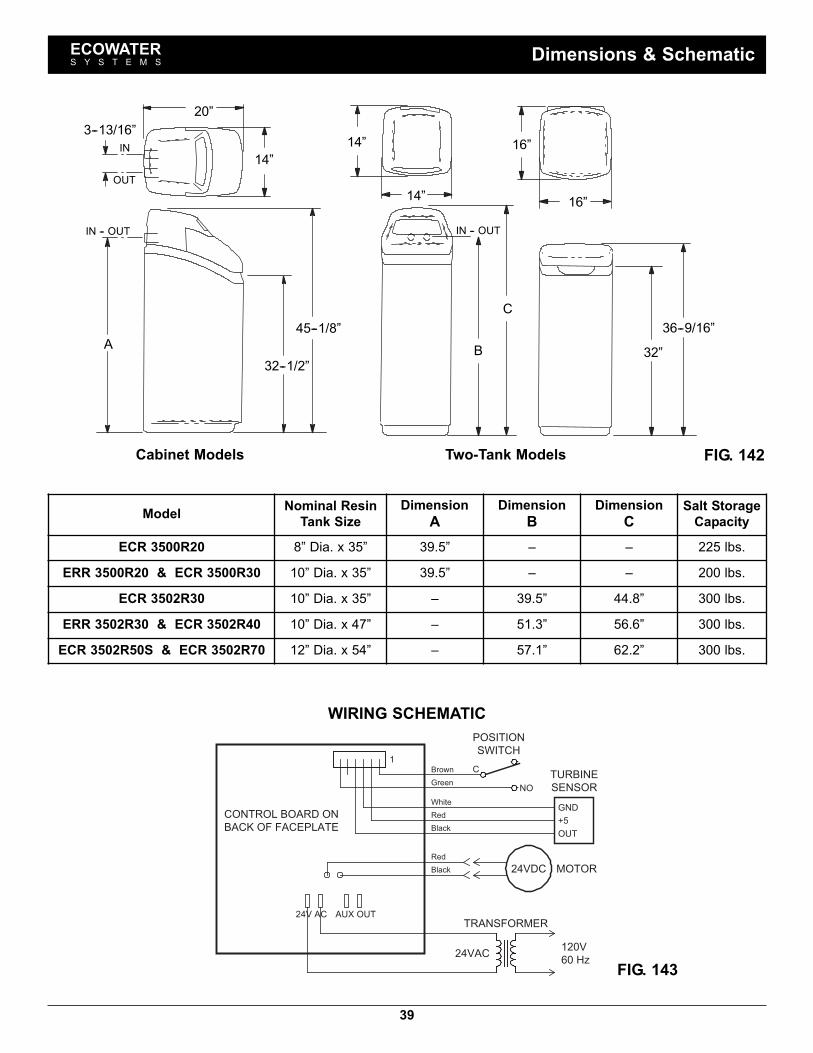
39
ECOWATERS Y S T E M S Dimensions & Schematic
IN
OUT
3--13/16”
32--1/2”
45--1/8”
A
IN -- OUTIN -- OUT
14”
20”
14”
14”
C
B
16”
16”
36--9/16”
32”
FIG. 142
Model Nominal ResinTank Size
DimensionA
DimensionB
DimensionC
Salt StorageCapacity
ECR 3500R20 8” Dia. x 35” 39.5” – – 225 lbs.ERR 3500R20 & ECR 3500R30 10” Dia. x 35” 39.5” – – 200 lbs.
ECR 3502R30 10” Dia. x 35” – 39.5” 44.8” 300 lbs.ERR 3502R30 & ECR 3502R40 10” Dia. x 47” – 51.3” 56.6” 300 lbs.ECR 3502R50S & ECR 3502R70 12” Dia. x 54” – 57.1” 62.2” 300 lbs.
Cabinet Models Two-Tank Models
WIRING SCHEMATIC
1
24VDC MOTOR
TRANSFORMER
24VAC120V
60 Hz
BACK OF FACEPLATE
CONTROL BOARD ON
SWITCH
POSITION
NO
+5
GND
OUT
TURBINE
SENSOR
Red
Black
Red
Black
White
Brown C
Green
AUX OUT24V AC
FIG. 143

40
ECOWATERS Y S T E M S Specifications & Performance Claims
p Intermittent flow rate does not represent the maximum service flow rate used for determining the unit’s rated capacity and effi-ciency. Continuous operation at flow rates greater than the service flow rate may affect capacity and efficiency performance.The validity of these flow rates is verified by Water Quality Association (WQA).
¢ Capacity to remove clear water iron is substantiated by WQA test data. State of Wisconsin requires additional treatment ifwater supply contains greater than 5 ppm clear water iron.
u Canada working pressure limits: 1.4 - 7.0 kg/cm².These units conform to NSF/ANSI 44 for the specific performance claims as verified and substantiated by test data.
SPECIFICATIONSECR
3500R20ERR
3500R20ECR
3500R30ECR
3502R30ERR
3502R30ECR
3502R40ECR
3502R50SECR
3502R70Model Code HR20 HR20+ HR30 2H30 2H30+ 2H40 2H50 2H70Rated Softening Capacity(Grains @ lb. Salt Dose)
5,700@ 1.116,800@ 4.320,400@ 7.5
6,200@ 1.117,400@ 5.222,200@ 8.9
8,300@ 1.625,000@ 6.430,200@ 11.3
8,300@ 1.625,000@ 6.430,200@ 11.3
7,500@ 1.721,400@ 6.427,500@ 11.0
11,300@ 2.233,200@ 8.540,100@ 14.8
21,600@ 4.539,500@ 11.050,000@ 17.4
32,900@ 6.257,600@ 12.871,500@ 25.6
Rated Efficiency (gr./lb. ofSalt at Min. Salt Dose) 5150 4440 5160 5160 4420 5150 4800 5310Water Used DuringRegeneration
4.6 gal. /1,000 grains
4.5 gal. /1,000 grains
4.5 gal. /1,000 grains
4.5 gal. /1,000 grains
4.5 gal. /1,000 grains
4.7 gal. /1,000 grains
3.8 gal. /1,000 grains
2.8 gal. /1,000 grains
Service Flow Rate (gpm) 9.0 9.0 11.0 11.0 10.0 12.0 20.0 12.0Pressure Drop at ServiceFlow Rate (psi) 10 8 8 8 8 13 13 11Intermittent Flow Rate(gpm) @ 15 psip 12.0 14.8 16.5 16.5 14.2 13.6 21.5 17.0Intermittent Flow Rate(gpm) @ 30 psip 19.4 23.6 25.8 25.8 21.4 21.6 32.2 22.0Amount of HighCapacity Resin (cu. ft.) 0.60 0.71 0.89 0.89 0.88 1.18 1.53 2.05Water Supply Max.Hardness (gpg) 40 50 60 60 60 75 95 125Water Supply Max. ClearWater Iron (ppm) ¢ 10 10 12 12 12 15 15 15Min.-Max. WorkingPressure (psi) u 20 - 125Min.-Max. OperatingTemperature (°F) 40 - 120Min. Water SupplyFlow Rate (gpm) 3Max. Flow Rate (gpm) toDrain during Recharge 2.4 3.0 3.0 3.0 3.0 3.0 5.0 5.4
These models are efficiency rated. The efficiency rating is valid only at the minimum salt dose and service flow rate. Thesofteners have a demand initiated regeneration (D.I.R) feature that complies with specific performance specificationsintended to minimize the amount of regenerant brine and water used in their operation.These softeners have a rated softener efficiency of not less than 3,350 grains of total hardness exchange per pound of salt(based on sodium chloride) and shall not deliver more salt than their listed rating or be operated at a sustained maximumservice flow rate greater than their listed rating. These softeners have been proven to deliver soft water for at least tencontinuous minutes at the rated service flow rate. The rated salt efficiency is measured by laboratory tests described inNSF/ANSI Standard 44. These tests represent the maximum possible efficiency that the system can achieve. Operationalefficiency is the actual efficiency after the system has been installed. It is typically less than the rated efficiency, due toindividual application factors including water hardness, water usage, and other contaminants that reduce a softener'scapacity.While testing was performed under standard laboratory conditions, actual performance of the system may vary based onlocal water conditions.

41
ECOWATERS Y S T E M S Specifications & Performance Claims
For future reference, enter the following information:Model No. ______________________ Installation Date _________________
Serial No. (includes date code) ____________________________________________
Water Hardness _________ GPG Iron Content _________ PPMModel No. and Serial No. are on the shipping carton and on the conditioner/refiner’s rating decal.
PERFORMANCE CLAIMSContaminant Influent Challenge Level Maximum Allowable
Product Water LevelBarium 10 ±10% mg/L 2.0 mg/LRadium 226/228 25 pCi/L 5 pCi/L
Substance Influent Challenge Level Reduction RequirementChlorine 2.0 ±10% mg/L 50%
Models ERR 3500R20 and ERR 3502R30 have been tested according to NSF/ANSI Standard 42 for the reduction of chlo-rine taste and odor. The concentration of the indicated substance in water entering the system was reduced to a concen-tration less than or equal to the permissible limit for water leaving the system, as specified in NSF/ANSI Standard 42.

42
ECOWATERS Y S T E M S Repair Parts
ECOWATER SYSTEMS CONDITIONER/REFINER ASSEMBLY1 2
Valve AssemblySee Pages 44 & 45
for parts
3467
591110
8
12
30
3332
34 35
36
37
13
2926
27 16
20 2117
18
1922
24
3928
3823
252021
15
22
14
13
18 1917
16
31

43
ECOWATER SYSTEMS CONDITIONER/REFINER ASSEMBLYKeyNo. Part No. Description1 7275907 Transformer, 24V, 10VA2 7292967 Repl. Remote (incl. batteries)3 7218662 Repl. Top Cover (cabinet models)4 7292941 Repl. Faceplate Assembly,
incl. decal & electronic control5 7291343 Support, Faceplate w/lens– 7331177 Tank Neck Clamp Kit
(includes 2 ea. of Key Nos. 6 & 7)6 á Clamp Section (2 req.)7 á Retainer Clip (2 req.)– 7112963 Distributor O-Ring Kit
(includes Key Nos. 8-10)8 á O-Ring, 2-7/8” x 3-1/4”9 á O-Ring, 13/16” x 1-1/16”10 á O-Ring, 2-3/4” x 3”11 7077870 Top Distributor12 7105047 Repl. Bottom Distributor
137304235 Resin Tank, 8” dia. x 35”7113066 Resin Tank, 10” dia. x 35”7092202 Resin Tank, 10” dia. x 47”7113074 Resin Tank, 12” dia. x 54”
140502272 Resin, 1 cu. ft. (standard mesh)7052202 Resin, 1 cu. ft. (fine mesh)7175149 Activated Carbon (refiner models)
15 7124415 Gravel, 17 lbs.16 7219888 Brinewell Cover17 7214375 Brinewell Assembly w/decal– 7331698 Brinewell Mounting Hardware Kit
(includes Key Nos. 18 & 19)18 á Washer19 á Screw– 7331258 Overflow Hose Adaptor Kit
(includes Key Nos. 20-22)20 á Grommet21 á Adaptor Elbow22 á Hose Clamp
KeyNo. Part No. Description23 7218604 Repl. Brine Tank (cabinet models)24 7287386 Rim (cabinet models)25 7214244 Vapor Barrier26 7291466 Salt Hole Cover Assembly27 7274008 Cover, Brine Tank (two-tank models)28 7218612 Repl. Brine Tank (two-tank models)
297310210
Brine Valve Assembly,(R20, ECR 3500R30, R50S & R70models)
7310197Brine Valve Assembly,(ECR 3502R30, ERR 3502R30 &R40 models)
307327568
Float, Stem & Guide Assembly(R20, ECR 3500R30, R50S & R70models)
7113008Float, Stem & Guide Assembly(ECR 3502R30, ERR 3502R30 &R40 models)
31 7171349 Cone Screen32 9003201 Nut-Ferrule (2 req.) Ù33 7094987 Union Connector Ù34 7161807 Tubing, 20 ft. Ù
7161768 Tubing, 100 ft. Ù35 7218670 Repl. Top Cover (two-tank models)36 7274286 Rim (two-tank models)
37
7111084 Repl. Tank Sleeve (ECR 3502R30)7218646 Repl. Tank Sleeve (ERR 3502R30
& ECR 3502R40)7111050 Repl. Tank Sleeve (ECR 3502R50S
& ECR 3502R70)38 7248706 Ground Clamp Kit Ù39 7214383 Bypass Valve Ù (includes 2 ea. of
Key Nos. 52 & 55)¢ 7108118 Drain Hose, 1/2” I.D.¢ Not illustratedÙ Optional parts, not included with conditioner/refiner
ECOWATERS Y S T E M S Repair Parts
To order parts, call your local EcoWater dealer or go towww.ecowater.com to locate a dealer in your area.

44
ECOWATERS Y S T E M S Repair Parts
VALVE ASSEMBLY
6869
58
69
6261
6667
63
5960
65
68
64
57
56
5554
5352
5150
83
70
71
72
73
7475
76
7980 81
78
77
88
82
61
62
60
8786
8584
8990
9796
95
98
91
929394

45
VALVE ASSEMBLYKeyNo. Part No. Description
–
7290931Turbine & Support Assembly(includes 1 ea. of Key Nos. 50, 51& 2 ea. of Key No. 52)(ECR 3500R20, ERR 3500R20,ECR 3500R30, ECR 3502R30)
7331703Turbine & Support Assembly(includes 1 ea. of Key Nos. 50, 51& 2 ea. of Key No. 52)(ERR 3502R30, ECR 3502R40,ECR 3502R50S, ECR 3502R70)
50 á Turbine51 á Turbine Support & Shaft52 7311127 O-Ring, 1-1/16” x 1-5/16” (2 req.)53 7077642 Copper Tube, 1” pipe (2 req.)54 7234553 Copper Tube, 1-1/4” pipe (2 req.)55 7089306 Clip Retainer (2 req.)56 7309811 Wire Harness w/pos. switch conn.57 7159949 Disc Valve Housing58 7078282 Inlet End Seal u59 7214286 Inlet Disc u60 7058216 Wave Washer (2 req.)61 7170220 O-Ring, 3/4” x 15/16” (3 req.) u62 7170296 O-Ring, 2-7/8” x 3-1/4” (2 req.)63 7077498 Inlet End Cap64 7142942 Clip, Drain65 7219066 Drain Nipple– 7141239 Drain Hose Adaptor (optional)66 7170327 O-Ring, 5/8” x 13/16”
67
1110600 Flow Plug, Fast Rinse, 2.4 gpm(ECR 3500R20)
7097969 Flow Plug, Fast Rinse, 3.0 gpm(ERR 3500R20, R30 & R40 models)
7097977 Flow Plug, Fast Rinse, 4.0 gpm(R50S & R70 models)
– 7331177 Tank Neck Clamp Kit(includes 2 ea. of Key Nos. 68 & 69)
68 á Retainer Clip (4 req.) v69 á Clamp Section (4 req.) v
–
7137507 Nozzle Venturi Assembly (includesKey Nos. 70-78) (ECR 3500R20w)
7091866Nozzle Venturi Assembly(includes Key Nos. 70-77)(ERR 3500R20, R30 & R40 models)
7085247Nozzle Venturi Assembly((includes Key Nos. 70-77)R50S & R70 models)
KeyNo. Part No. Description70 7199729 Cap71 7170262 O-Ring, 1-1/8” x 1-3/8”72 7167659 Screen Support73 7146043 Screen
747187772 Nozzle Venturi (red) & Gasket Kit
(R20w, R30 & R40 models)7114533 Nozzle Venturi (blue) & Gasket Kit
(R50S & R70 models)7204362 Gasket Only (black)
75 1148800 Flow Plug, Fill, 0.3 gpm76 7081104 Housing, Nozzle & Venturi77 7095030 Cone Screen78 7084607 Flow Plug, 0.15 gpm
(ECR 3500R20w)79 7292323 O-Ring, .171” x .449”80 7120526 Elbow, 90°81 1202600 Nut - Ferrule82 7170319 O-Ring, 1/4” x 3/8” (2 req.)83 7081201 Clip, Nozzle & Venturi84 7078313 Retainer x
857104774 Flow Washer, Backwash, 1.0 gpm
(ECR 3500R20) x
7104570Flow Washer, Backwash, 1.7 gpm(ERR 3500R20, R30 & R40 models)- not used on R50S & R70 modelsx
86 7214278 Outlet Disc u87 7078274 Outlet End Seal u88 7091329 Driver, Outlet Disc89 7159965 Outlet End Cap90 7283497 Cam & Gear91 7203104 Washerhead Screw, #8-18 x 1/2”92 7281275 Motor, incl. Key No. 9393 7289702 Bracket, Motor94 7168524 Screw, #10-32 x 5/16” (3 req.)95 7103972 Screw, #8-18 x 7/16” (2 req.)96 7140738 Screw, #4-24 x 3/4”97 7145186 Switch98 7140746 Expansion Pinu Included in Disc Kit, #7218688v Not all parts are shownw Use red nozzle along with Key No. 77 on water pres-sures of 50 psi and less.
x Order Key Nos. 84 & 85 if needed
ECOWATERS Y S T E M S Repair Parts

46
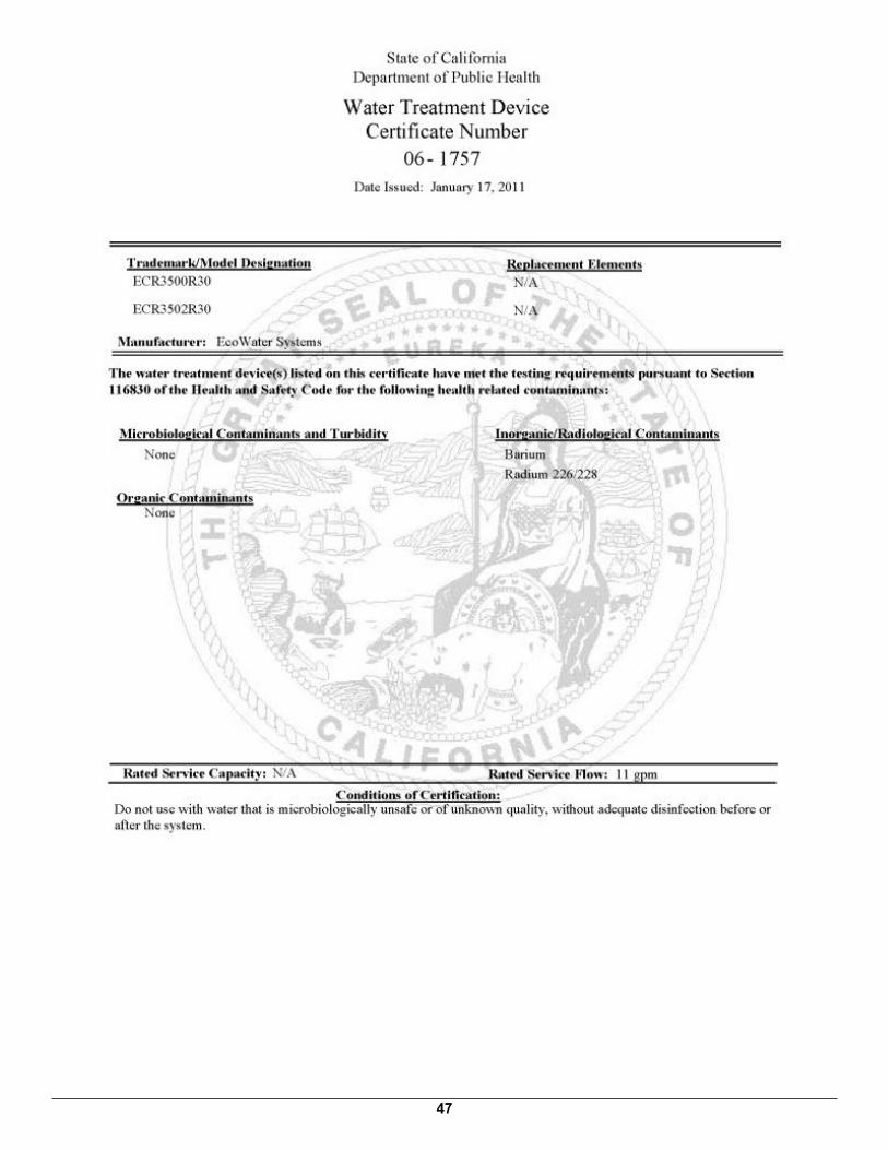
47

48

49
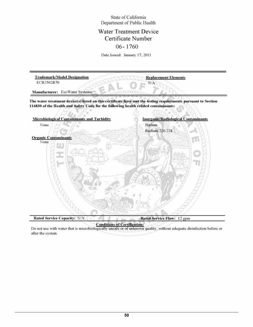
50
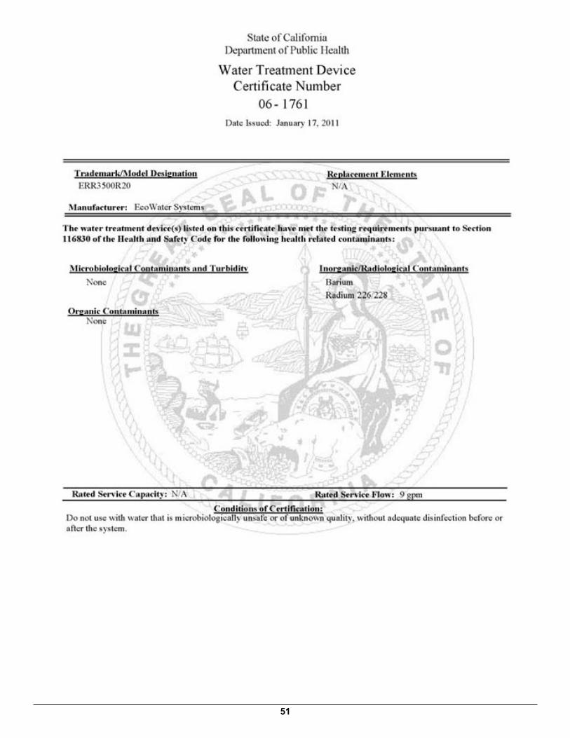
51

FOR IOWA USE ONLYAll sales in Iowa require the following signature before consummation of sale. These signatures must be retained byseller/renter for 2 years minimum.Buyer/Renter __________________________________________________________ Date _________________Seller ________________________________________________________________ Date _________________Seller’s Address _______________________________________________________________________________Seller’s Phone No. _____________________________________________________________________________
EcoWater Systems Digital Demand Water System – ECR / ERR Series 3500 or 3502
– – – – – – – – – – – – – – – – – – – – – – – – –"