softener manual - watersoft inc. softener...installation-installation procedure-- water supply...
TRANSCRIPT

Softener ManualInstallation / Operation Manual
Fully Automatic & DemandWater Softeners
with 2092 Isobar Control Valve

Softener Specifications.................................................................................................Page 3
Softener Installation......................................................................................................Page 5
Softener Capacity..........................................................................................................Page 10
Installing the Control Valve..........................................................................................Page 13
WARNING
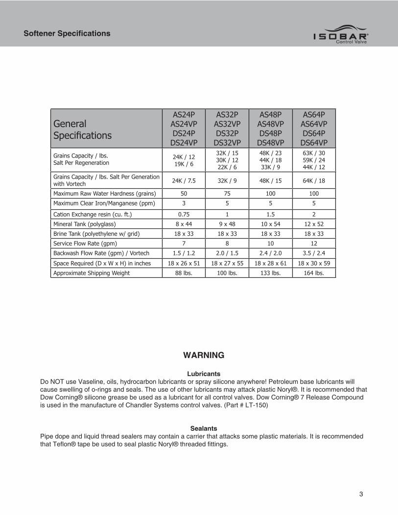
LubricantsDo NOT use Vaseline, oils, hydrocarbon lubricants or spray silicone anywhere! Petroleum base lubricants will cause swelling of o-rings and seals. The use of other lubricants may attack plastic Noryl®. It is recommended that Dow Corning® silicone grease be used as a lubricant for all control valves. Dow Corning® 7 Release Compound is used in the manufacture of Chandler Systems control valves. (Part # LT-150)
SealantsPipe dope and liquid thread sealers may contain a carrier that attacks some plastic materials. It is recommended that Teflon® tape be used to seal plastic Noryl® threaded fittings.
Softener Specifications
3
GeneralSpecifications
AS24PAS24VPDS24PDS24VP
AS32PAS32VPDS32PDS32VP
AS48PAS48VPDS48PDS48VP
AS64PAS64VPDS64PDS64VP
Grains Capacity / lbs. Salt Per Regeneration
24K / 1219K / 6
32K / 1530K / 1222K / 6
48K / 2344K / 1833K / 9
63K / 3059K / 2444K / 12
Grains Capacity / lbs. Salt Per Generation with Vortech 24K / 7.5 32K / 9 48K / 15 64K / 18
Maximum Raw Water Hardness (grains) 50 75 100 100Maximum Clear Iron/Manganese (ppm) 3 5 5 5
Cation Exchange resin (cu. ft.) 0.75 1 1.5 2Mineral Tank (polyglass) 8 x 44 9 x 48 10 x 54 12 x 52Brine Tank (polyethylene w/ grid) 18 x 33 18 x 33 18 x 33 18 x 33Service Flow Rate (gpm) 7 8 10 12Backwash Flow Rate (gpm) / Vortech 1.5 / 1.2 2.0 / 1.5 2.4 / 2.0 3.5 / 2.4Space Required (D x W x H) in inches 18 x 26 x 51 18 x 27 x 55 18 x 28 x 61 18 x 30 x 59Approximate Shipping Weight 88 lbs. 100 lbs. 133 lbs. 164 lbs.
PLEASE NOTE THESE SPECIFICATIONS BEFORE PROCEEDING
OPERATING PRESSURE RANGE : 20 - 125 PSIOPERATING TEMPERATURE RANGE : 33º F - 120º F
INLET / OUTLET PIPE SIZE : 3/4: FNPT
PLEASE COMPLY WITH ALL APPLICABLE PLUMBING CODES
PROTECT THE SOFTENER AND PIPING FROM FREEZING TEMPERATURES
Please read the entire Owner’s Manual and Instruction before installation.This Owner’s Manual must stay with the unit.
-How A Water Softener Works-
Water hardness is derived from Calcium and Magnesium minerals that have been dissolved into the water under the earth’s surface. These minerals are found in limestone deposits and are the source of hard water. The amount of hardness in a given water supply is dependent upon the quantity of Calcium and Magnesium present and the length of time water has been in contact with them. This can vary dramatically from well-to-well and, for this reason, a water analysis is imperative in order to determine the proper treatment method. The degree of hardness increas-es as the concentration of Calcium and Magnesium “ions” increase and is measured in Grains Per Gallon (gpg).
The problem of hard water in the home / business comes to light in many facets of daily use. Water spots and scum left behind on bathtubs, fixtures and showers; wear and tear on appliances; calcium build-up in hot water heaters and piping; and, greater amounts of soap and detergents being used are just a few examples.
The modern water softener is designed to reduce hardness ions and their unpleasant side effects. Special resin beads in the softener mineral tank are used to change hard water into soft water. The surfaces of these beads are covered with sodium ions. As hard water enters the mineral tank and comes into contact with the resin, an ex-change of ions takes place as dissolved Calcium and Magnesium ions cling to the resin surface and sodium ions take their place, thus softening the water. This process is called Ion Exchange. Over time, the sodium ions used for the exchange process become depleted and must be replenished.
The water softener provides a Regeneration process whereby brine solution enters the mineral tank, driving-off the collected hardness ions and replenishes the surface of the resin beads with more sodium ions. This process is automatically initiated by the control valve on the mineral tank. The regeneration process has five basic cycles as follows:
1. Backwash - The control valve directs the water flow in a reverse direction through the mineral tank, separating the resin beads and flushing any accumulated particles to a waste drain.
2. Brine & Rinse - In the first part of this cycle, the control valve directs brine solution downward through the mineral tank, driving-off collected hardness ions and replenishing the resin beads with sodium ions. The second part of the cycle rinses hardness ions and excess brine from the mineral tank to the waste drain.
3. Rapid Rinse - The control valve directs the water flow downward, settling and recompacting the resin bed.
4. Brine Refill - The control valve directs fresh water into the salt compartment to create new brine solution for the next scheduled regeneration.
5. Service - This is the normal “operating” cycle where hard water enters the mineral tank, comes into contact with the resin beads and exchanges hardness ions for sodium ions - the water then becomes “soft” and ready for use.
Softener Specifications
4

Softener Specifications
-Pre-Installation Check List-
A water test should always be performed in order to determine total water hardness (in gpg) and total dis-solved iron (in parts per million - ppm). This is critical for proper equipment selection, sizing and for determining the program for regeneration frequency. If heavy concentrations of iron (above 5 ppm), iron coloration, iron bac-teria or sediment are present, filtration prior to the softener will most generally be required. Certain states may require a licensed plumber for installation.
Note : Flexible water supply connectors and flexible drain line tubing may not be allowed in you locale. Please check with local plumbing code officials prior to installation.
Installation Requirements• A level floor position ahead of piping into water heater.• Unit must be installed at least 10’ ahead of the inlet to a water heater to prevent damage due to back-up of hot water.• DO NOT install the unit in an area of direct sunlight or where freezing temperatures may occur! (See Installation Diagrams for proper placement and plumbing connections.)
-Major System Components-1. Brine Tank - This tank holds the salt that is added to the softener. This salt is dissolved with water to form a brine solution used in the softener regeneration process.2. Resin Tank - This tank contains the ion exchange resin media. Water flows through the resin tank under pres sure to come into contact with the resin for water softening.3. Control Valve - The valve directs water through the resin tank for water softening and controls the flow of water / brine for the regeneration process.
Installation
5

Installation
-Softener Location / Other Requirements-
• Locate the unit near an unswitched, 120 volt / 60 Hz grounded electrical outlet.• Check for distance and proper drain installation (e.g. floor drain, washing machine standpipe).• Determine type and size of piping required for softener connection (e.g. copper, galvanized, PVC plastic).
Note• If household plumbing is galvanized and you intend to make the installation with copper (or vise versa), obtain di-electric unions to prevent dissimilar metal corrosion.• Where the drain line is elevated above the control valve or exceeds 20 feet in length to reach the drain, use 3/4" I.D. drain line tubing instead of 1/2" I.D. Drain line tubing is not included.• All plumbing lines not requiring “soft” water should be connected “upstream” of the softener. • The brine tank drain line is gravity flow and must discharge below the overflow fitting.• The brine overflow is provided as a back-up in the event the safety float shut-off should fail, allowing the brine tank to overfill. This drain connection would then carry the excess water to the drain and prevent flooding of the floor. Therefore, no liability will or can be assumed by the manufacturer of the softener should this occur.
Caution • If sweat soldering copper pipe (remember to always use lead free solder and flux), cover yoke and bypass valve with wet rags to prevent heat damage to connections and control valve! If using PVC or plastic pipe primers and solvent cements specifically recommended for use with potable water are required.
• Do not “TEE” to the main drain line from control valve.
6
Installation
-Installation Procedure-
- Water Supply Connections and Bypass Valve -
To allow for softener servicing, swimming pool filling or lawn sprinkling, a manual bypass valve has been installedat the factory. The bypass allows hard water to be manually routed around the softener.
1. Position softener at desired location for installation. (See Installation Diagrams.)
2. For AS96V & DS96V Units ONLY - The resin material is shipped separately from the mineral tank. Remove the valve by unscrewing from center hole. Use a cork or tape to place over top of distributor tube to prevent material from entering tube while filling. Place funnel in hole. Pour several gallons of water in the tank.
No gravel is required. Pour in the resin material. Remove funnel and cork or tape from distributor tube. Clean tank threads and fill the mineral tank completely with water. Replace the valve, being careful to position the distributor tube into the distributor tube pilot hole.
Note : If rebedding an existing unit and the system utilizes a standard tube & basket style distributor, a “D” gravel underbedding will be required.
3. Turn OFF main water supply and OPEN nearest faucet to relieve pressure.4. Cut main line and install appropriate elbows and extensions. Inlet and outlet connections on the control valve are 3/4” FNPT. (1” FNPT for AS96V & DS96V units.)
Caution : Raised arrows located on the sides of control valve body and bypass valve indicate proper direction of water flow. Install inlet and outlet piping in direction of arrows.
6. Rotate bypass valve to the bypass position (position of lever is at right angle to inlet / outlet piping).
7. Turn the main supply line on to restore water service to the home.
8. OPEN nearest faucet to evacuate air and repressurize plumbing lines.
9. Check for leaks!
-Drain Line Connection-
1. Pull out clip and remove drain line assembly located on the left side of control valve. Remove drain line hose barb and wrap threads with Teflon tape. Reinstall drain line hose barb. Caution : Hand tighten only!!! Replace drain line assembly and reinstall clip.
2. Install 1/2” I.D. drain line tubing (not included) from hose barb to an open drain. A 4” gap between the end of the drain line and the open drain is required to prevent waste water backflow. Keep the drain line as short as possible. An overhead drain line can be used if necessary, but should discharge below the control valve. A syphon trap (taped loop) at the outlet of the drain line is advisable to keep the drain line full and assure correct flow during regeneration. Elbows or other fittings must be kept at a bare minimum.
Note: Where the drain line is elevated above the control valve or exceeds 20’ in length, 3/4” I.D. drain line tubing should be used.
Installation
7

Installation
-Brine Line and Overflow Connection-
1. Position brine tank on a smooth, level surface near the softener resin tank. If necessary, the brine tank can be placed at a higher level than the resin tank, but never at a lower level.
2. Install one end of 3/8" O.D. by 1/4" I.D. brine line tubing (included with unit) to push lock fitting located on left side of control valve.
3. Remove brine tank cover.
4. Remove cap from brine well.
5. Insert opposite end of brine line through outer hole in brine tank.
6. Connect brine line to compression fitting on safety brine valve located inside brine well. Replace brine well cap.
7. Install 1/2" I.D. drain line tubing (not included) to the overflow fitting on brine tank located just below the brine line.
8. Run the opposite end of brine tank drain line to a suitable drain.
NOTE: The brine tank drain line is gravity flow and must discharge below the overflow fitting.
CAUTION: DO NOT “TEE” to the main drain line from control valve.
NOTE: The brine overflow is provided as a back-up in the event the safety float shut-off should fail, allowing the brine tank to overfill. This drain connection would then carry the excess water to the drain and prevent flooding of the floor. Therefore, no liability will or can be assumed by the manufacturer of the softener should this occur.
-Electrical Connection-
1. Plug the cord from the control valve into a standard 115 volt / 60 Hz receptacle.
NOTE: DO NOT plug into an outlet controlled by a wall switch or pull chain that could inadvertently be turned off.
2. For your protection, this unit is equipped with a 3-prong plug and should be plugged into a grounded receptacle is designed only to accept 2-prong plugs, obtain a 3-prong adapter and secure the ground wire to the receptacle plate mounting screw.
WARNING: DO NOT remove grounding plug!! An improperly grounded unit could cause injury from electrical shock!
-Pressurizing The System-
1. Remove control valve cover or cabinet lid to access control panel. (See Figure 1.)2. The control valve must be in the Service position! The word SERVICE is imprinted in the notch on the manual regeneration knob. (See Figure 1.) If needed, rotate the manual regeneration knob CLOCKWISE to this position.WARNING: NEVER turn regeneration knob counter clockwise as this will cause damage to the control valve!3. Slowly rotate the bypass valve to the SERVICE position. The handle will be parallel with the plumbing lines.4. Open the nearest faucet to evacuate air from plumbing lines.5. Check for leaks!!!
8

Installation Installation
- Control Valve Options-
Each control valve position can be manually selected by rotating the regeneration knob CLOCKWISEuntil the desired position appears in the knob notch.
1. Manually index regeneration knob to BACKWASH position and allow water to run to drain for 3-4 minutes.2. Manually index regeneration knob to BRINE REFILL position and allow the brine tank to fill just over the salt grid plate.3. Manually index regeneration knob to BRINE & RINSE position and allow the control valve to draw water from the brine tank until it stops.4. Manually index regeneration knob to SERVICE position.
9
- Setting the Regeneration Schedule -
1. Locate the skipper wheel just to the right of the manual regeneration knob. (See Figure 1.)2. Rotate skipper wheel until the red pointer covers the number "1".NOTE: The red pointer represents tonight in the regeneration program. (See Figure 1.)3. Select the capacity chart (beginning on page 8) that corresponds with the capacity of the softener.4. Select the salt setting to be used and use this section of the capacity chart.NOTE: Salt settings are pre-set at the factory for the maximum shown on the capacity chart. If an economy salt setting is desired, contact factory.WARNING: Do not reduce salt settings below 9 lbs. as the water level in the brine tank will not reach the grid plate.5. Follow along the line indicating the number of persons in the family to the column that corresponds with the hardness range. This will indicate how many tabs on the skipper wheel will need to be slid out. (See Figure 2.)NOTE: If the water contains iron and / or manganese, multiply the total parts per million (ppm) by four (4) and then add to the grains per gallon (gpg) of hardness. Use this COMPENSATED HARDNESS level when programming the regeneration frequency.
6. Next, find the regeneration schedule chart. Follow along the line corresponding with the number found in the capacity chart. These are the actual tab numbers on the skipper wheel that need slid out exposing the tab end. (See Figure 3.)

Capacity
Model Nominal 32,000 Grain Units (-32)
# of People 1 2 3 4 5 6 7 8 9
Salt Setting 15 lbs. / Regeneration
Hardness Range Number Of Tabs To Pull
3 - 10 1 1 1 2 2 2 2 3 3
11 - 20 1 2 2 3 3 4 4 4 4
21 - 30 1 2 3 4 6 6 6 12 12
31 - 40 2 3 4 6 6 12 12 12 -
41 - 50 2 3 6 6 12 12 12 12 -
51 - 60 2 4 6 12 12 12 12 - -
61 - 75 2 4 6 12 12 12 - - -
NOTE: The number found in the above sample chart is the number of program tabs that will need to be pulled (slide out) on the program wheel. Simply align the Number of People with the Compensated Hardness to find the number of tabs to slide. When you have determined the number of tabs to slide, consult the regeneration frequency chart below to find the actual “tab number(s)” to slide out on the program wheel.
Figure 3
Regeneration Frequency Slide Out TAB NUMBER
(# of Tabs Out) 1 2 3 4 5 6 7 8 9 10 11 12
12 ● ● ● ● ● ● ● ● ● ● ● ●6 ● ● ● ● ● ●4 ● ● ● ●3 ● ● ●2 ● ●1 ●
NOTE: Figure 1 shows the skipper wheel set for the example (every 2 days).
Figure 2
10
- How To Use The Capacity Charts -
EXAMPLEHARDNESS = 20 gpg 20 gpg UNIT SELECTED 32,000 GRAIN
IRON = 3 ppm X 4 12 gpg NUMBER OF PERSONS 4
MANGANESE = 1 ppm X 4 4 gpg COMPENSATED HARDNESS 36 gpg
TOTAL COMPENSATED HARDNESS 36 gpg SALT SETTING 15 LB/ REG

Capacity Capacity
Model Nominal 24,000 Grain Unit (- 24)
# of People 1 2 3 4 5 6 7 8 9
Salt Setting 12 lbs. / Regeneration
Hardness Range Number of Pins to Pull
3 - 10 1 1 1 2 2 2 2 3 3
11 - 20 1 2 2 3 3 4 4 4 4
21 - 30 1 2 3 4 6 6 6 12 12
31 - 40 2 3 4 6 6 12 12 12 -
41 - 50 2 3 6 6 12 12 12 12 -
51 - 60 2 4 6 12 12 12 12 - -
61 - 75 2 4 6 12 12 12 - - -
NOTE: All of these charts assume 75 gallons per person per day usage.
Regeneration Frequency Slide Out TAB NUMBER
(# of Tabs Out) 1 2 3 4 5 6 7 8 9 10 11 12
12 ● ● ● ● ● ● ● ● ● ● ● ●6 ● ● ● ● ● ●4 ● ● ● ●3 ● ● ●2 ● ●1 ●
Model Nominal 32,000 Grain Units (- 32)
# of People 1 2 3 4 5 6 7 8 9
Salt Setting 15 lbs. / Regeneration
Hardness Range Number of Pins to Pull
3 - 10 1 1 1 2 2 2 2 3 3
11 - 20 1 2 2 3 3 4 4 6 6
21 - 30 1 2 3 4 6 6 6 12 12
31 - 40 2 3 4 6 6 12 12 12 -
41 - 50 2 3 6 6 12 12 12 12 -
51 - 60 2 4 6 12 12 12 12 - -
61 - 75 2 4 6 12 12 12 - - -
11
Capacity
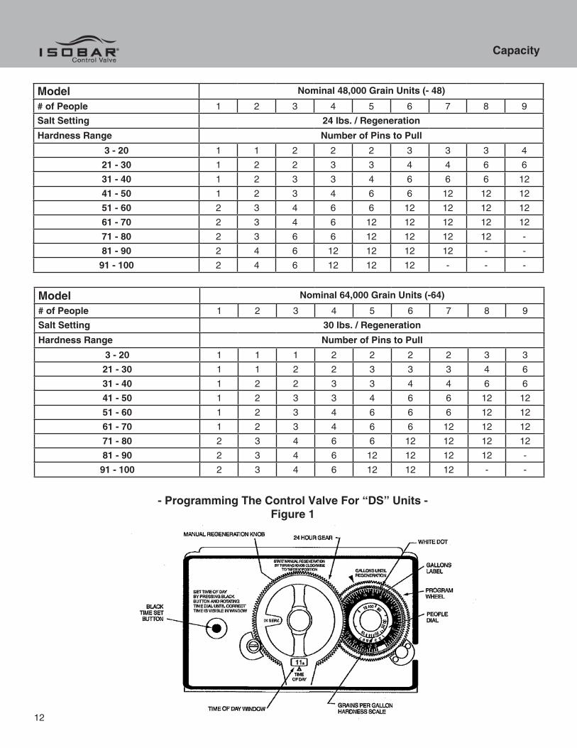
Model Nominal 48,000 Grain Units (- 48)
# of People 1 2 3 4 5 6 7 8 9
Salt Setting 24 lbs. / Regeneration
Hardness Range Number of Pins to Pull
3 - 20 1 1 2 2 2 3 3 3 4
21 - 30 1 2 2 3 3 4 4 6 6
31 - 40 1 2 3 3 4 6 6 6 12
41 - 50 1 2 3 4 6 6 12 12 12
51 - 60 2 3 4 6 6 12 12 12 12
61 - 70 2 3 4 6 12 12 12 12 12
71 - 80 2 3 6 6 12 12 12 12 -
81 - 90 2 4 6 12 12 12 12 - -
91 - 100 2 4 6 12 12 12 - - -
Model Nominal 64,000 Grain Units (-64)
# of People 1 2 3 4 5 6 7 8 9
Salt Setting 30 lbs. / Regeneration
Hardness Range Number of Pins to Pull
3 - 20 1 1 1 2 2 2 2 3 3
21 - 30 1 1 2 2 3 3 3 4 6
31 - 40 1 2 2 3 3 4 4 6 6
41 - 50 1 2 3 3 4 6 6 12 12
51 - 60 1 2 3 4 6 6 6 12 12
61 - 70 1 2 3 4 6 6 12 12 12
71 - 80 2 3 4 6 6 12 12 12 12
81 - 90 2 3 4 6 12 12 12 12 -
91 - 100 2 3 4 6 12 12 12 - -
- Programming The Control Valve For “DS” Units -Figure 1
12

Capacity
- Setting The Regeneration Schedule -
1. Locate the program wheel just to right of the manual regeneration knob. (See Figure 1.)2. Rotate program wheel until the white dot located on the outermost gear is aligned with the capacity (gallons) arrow on the control panel. (See Figure 1.)3. Place your thumb firmly on the white dot to hold the outer gear while setting the program wheel.4. Lift out the “people” dial and rotate it so that the number of people in the family is aligned with the compensated hardness in grains per gallon. The capacity arrow will not be aligned to the gallons of water that will be used between each regeneration as shown on the gallons label located outside the “people” dial. (See Figure 1.) If preferred, the unit can be set by gallons using this procedure. To calculate gallons, divide the grain capacity of the unit by the compensated hardness level. It is then advisable to subtract one day of water usage to provide a reserve. This setting will assume ample soft water for the family and automatically set a reserve capacity into the system.5. Push the meter cable firmly into the meter module on the back of the control valve, if not already in.
NOTE: Salt settings are pre-set at the factory for the maximum shown on the capacity chart. Salt settings should never be reduced on Demand Regeneration systems as a different volume of reserve capacity will be used before each regeneration. If the water contains iron and / or manganese, multiply the total parts per million (ppm) by four (4) and then add to the grains per gallon (gpg) of hardness. Use this compensated hardness level when programming the regeneration frequency.
WARNING: DO NOT reduce salt setting below 9 lbs. as the water level in the brine tank will not reach the grid plate.
Operation, Care and Cleaning
- Operation Of Bypass Valve -
When the handle on the bypass valve is in the SERVICE position, it will be parallel with the plumbing lines. Water is directed through the water softener. Water may be bypassed by turning the handle to the BYPASS horizontally. Water to the home will bypass the softener and be “untreated”.
You should manually bypass the softener if :
1. The outside lines do not bypass the water softener and water is to be used for lawn sprinkling or other similar uses.2. Servicing the water softener.3. A water leak from the water softener is evident.4. Shock Treating water well and piping with chlorine or other disinfectant.
- Extra Regeneration -
If soft water demands are unusually heavy, an extra regeneration can be initiated manually :
1. Remove the control valve face cover or remove cabinet lid to access control panel.2. Rotate manual regeneration knob CLOCKWISE until REGEN appears in knob notch.
CAUTION: DO NOT rotate regeneration knob COUNTER CLOCKWISE, as this will cause damage to the control valve! If the REGEN position is passed, continue around to SERVICE position and start again.
3. Regeneration will begin immediately and the softener will automatically return to the SERVICE position.
Note: Water will not start flowing for several minutes.
4. Replace control valve face cover or replace cabinet lid.
Installing the Control Valve
13

- General Care and Cleaning -
1. Do not place heavy or sharp objects on water softener or cabinet.2. Use only mild soap and warm water to clean exterior of the unit. Never use harsh, abrasive cleaners.3. Protect the water softener and drain line from freezing.4. Reset time for daylight saving time periods.5. Replace 9-volt battery once a year.6. Inspect and clean the brine tank when sediment appears in the bottom of the salt compartment.7. Always keep the brine tank supplied with good quality salt, a type designed for use in water softeners.
Servicing Instructions
- Changing The Salt -
1. Unplug electrical cord from outlet.2. Remove the control valve back cover.3. Locate salt dosage cam.4. Loosen salt dosage cam set screw.5. Rotate salt dosage cam until pointer lines up with desired salt setting.6. Tighten set screw.7. Replace control valve back cover.8. Plug electrical cord into outlet.9. Rest time of day.
14
Installing the Control Valve

Installing the Control Valve

710 Orange Street, Ashland, OH 44805 PH 419.289.1500 FAX 419.289.1515 www.watersoftinc.com