owner's manual craftsmanowner's manual craftsman garden tractor 25.0 hp, 48" mower...
TRANSCRIPT

Owner's Manual
CRAFTSMAN°
GARDEN TRACTOR25.0 HP, 48" MowerElectric StartAutomatic Transmission
Model No.917.276022
This product has a low emission engine which operates
from built Before start thedifferently previously engines. youengine, read and understand this Owner's Manual,
IMPORTANT:
Read and follow all SafetyRules and Instructions before
operating this equipment.
For answers to your questions
about this product, Call:
1-800-659-5917Sears Craftsman Help Line5 am - 5 pm, Mon- Sat
Sears, Roebuck and Co., Hoffman Estates, IL 60179 U.S.A.Visit our Craftsman website:www.sears.com/craftsman

Warranty ................................................ 2Safety Rules .......................................... 3Product Specifications ........................... 5Assembly/Pre-Operation ....................... 7Operation ............................................... 9Maintenance Schedule ........................ 16
Maintenance ........................................ 16Service and Adjustments ..................... 20Storage ................................................ 29Troubleshooting ................................... 30Repair Parts ......................................... 34Sears Service ........................ Back Cover
LIMITED WARRANTY ON CRAFTSMAN RIDING EQUIPMENTFor two (2) years from the date of purchase, if this Craftsman Riding Equipment ismaintained, lubricated and tuned up according to the instructions in the owner's manual,Sears will repair or replace free of charge any parts that are found to be defective inmaterial or workmanship according to the guidelines of coverage listed below. Sears willalso provide free labor for these applicable warranted parts for the two full years. Duringthe first 30 days of purchase, there will be no charges to service the product at yourhome for issues covered by this warranty. (See exclusions below). For your conve-nience, IN HOME warranty service will still be available after the first 30 days of pur-chase, but a trip charge will apply. This charge will be waived if the Craftsman product isdropped off at an authorized Sears location. For the nearest authorized Sears location,please call 1-800-4-MY-HOME®. This warranty applies only while this product is withinthe United States.
This Warranty does not cover:• Expendable items which become worn during normal use, including but not limited to
blades, spark plugs, air cleaners, belts, and oil filters.• Standard Maintenance Servicing, oil changes, or tune-ups.• Tire replacement or repair caused by punctures from outside objects, such as nails,
thorns, stumps, or glass.• Repairs necessary because of operator abuse, including but not limited to, damage
caused by towing objects beyond the capability of the riding equipment, impactingobjects that bend the frame or crankshaft, or over-speeding the engine.
• Repairs necessary because of operator negligence, including but not limited to, elec-trical and mechanical damage caused by improper storage, failure to use the propergrade and amount of engine oil, failure to keep the deck clear of flammable debris,or failure to maintain the equipment according to the instructions contained in theowner's manual.
• Engine (fuel system) cleaning or repairs caused by fuel determined to be contami-nated or oxidized (stale). In general, fuel should be used within 30 days of its pur-chase date.
• Normal deterioration and wear of the exterior finishes, or product label replacement.• Riding equipment used for commercial or rental purposes.
LIMITED WARRANTY ON BATTERY
For ninety (90) days from date of purchase, if any battery included with this riding equip-ment proves defective in material or workmanship and our testing determines the batterywill not hold a charge, Sears will replace the battery at no charge. During the first 30days of purchase, there will be no charges to replace the battery at your HOME. Afterthe first 30 days, for your convenience, IN-HOME warranty service will still be avail-able but a trip charge will apply. This charge will be waived if the Craftsman product isdropped off at an authorized Sears location. For the nearest authorized Sears location,please call 1-800-4-MY-HOME®.
This battery warranty applies only while this product is within the United States.
This warranty gives you specific legal rights, and you may also have other rights, whichvary, from state to state.
Sears, Roebuck and Co.,Dept.817WA, Hoffman Estates, IL 60179

IMPORTANT:This cuttingmachineis capableof amputatinghandsandfeet and throw-ing objects.Failureto observethe followingsafety instructionscouldresult in seriousinjuryor death.
WARNING: In order to preventac-cidentalstartingwhensettingup, trans-porting,adjustingor makingrepairs,alwaysdisconnectsparkplugwire andplacewire where it cannot contactsparkplug.
WARNING: Donot coast downahill in neutral,youmay lose controlof thetractor.
WARNING: Towonlythe attachmentsthat are recommendedby and complywithspecificationsof the manufacturerof yourtractor.Usecommonsensewhen towing.Operateonly at the lowestpossiblespeedwhen on a slope. Tooheavyof a load,while on a slope, is dangerous. Tirescanlosetractionwith the groundand causeyou to lose controlof your tractor.
WARNING:Engineexhaust,someof its constituents,and certain vehiclecomponentscontainor emit chemicalsknownto the State of Californiato causecancerand birthdefectsor other reproduc-tive harm.
WARNING:Batteryposts,terminalsand relatedaccessoriescontain lead andleadcompounds,chemicalsknownto theStateof Californiato cause cancerandbirthdefectsor other reproductiveharm.Wash hands after handling.
I. GENERAL OPERATION
• Read, understand, and follow all instruc-tions in the manual and on the machine
before starting.• Only allow responsible adults, who are
familiar with the instructions, to operatethe machine.
• Clear the area of objects such as rocks,toys, wire, etc., which could be pickedup and thrown by the blade.
• Be sure the area is clear of other peoplebefore mowing. Stop machine if anyoneenters the area.
• Never carry passengers.• Do not mow in reverse unless abso-
lutely necessary. Always look down andbehind before and while backing.
• Be aware of the mower discharge direc-tion and do not point it at anyone. Donot operate the mower without eitherthe entire grass catcher or the guard inplace.
• Slow down before turning.• Never leave a running machine unat-
tended. Always turn off blades, setparking brake, stop engine, and removekeys before dismounting.
• Turn off blades when not mowing.• Stop engine before removing grass
catcher or unclogging chute.• Mow only in daylight or good artificial
light.• Do not operate the machine while under
the influence of alcohol or drugs.• Watch for traffic when operating near or
crossing roadways.• Use extra care when loading or un-
loading the machine into a trailer ortruck.
• Data indicates that operators, age 60years and above, are involved in a largepercentage of riding mower-related in-juries. These operators should evaluatetheir ability to operate the riding mowersafely enough to protect themselves andothers from serious injury.
• Keep machine free of grass, leaves orother debris build-up which can touchhot exhaust / engine parts and burn. Donot allow the mower deck to plow leavesor other debris which can cause build-
up to occur. Clean any oil or fuelspillage before operating or storing themachine. Allow machine to cool before
storage.
II. SLOPE OPERATION
Slopes are a major factor related to loss-of-control and tipover accidents, which canresult in severe injury or death. All slopesrequire extra caution. If you cannot backup the slope or if you feel uneasy on it, donot mow it.
3

DO:
• Mow up and down slopes, not across.• Remove obstacles such as rocks, tree
limbs, etc.• Watch for holes, ruts, or bumps. Un-
even terrain could overturn the machine.
Tall grass can hide obstacles.• Use slow speed. Choose a low gear
so that you will not have to stop or shiftwhile on the slope.
• Follow the manufacturer's recommend-ations for wheel weights or counter-weights to improve stability.
• Use extra care with grass catchers orother attachments. These can changethe stability of the machine.
• Keep all movement on the slopes slowand gradual Do not make suddenchanges in speed or direction.
• Avoid starting or stopping on a slope. Iftires lose traction, disengage the bladesand proceed slowly straight down theslope.
DO NOT:
• Do not turn on slopes unless neces-sary, and then, turn slowly and graduallydownhill, if possible.
• Do not mow near drop-offs, ditches,or embankments. The mower could
suddenly turn over if a wheel is overthe edge of a cliff or ditch, or if an edgecaves in.
• Do not mow on wet grass. Reducedtraction could cause sliding.
• Do not try to stabilize the machine byputting your foot on the ground.
• Do not use grass catcher on steepslopes.
III. CHILDREN
Tragic accidents can occur if the operatoris not alert to the presence of children.Children are often attracted to the ma-chine and the mowing activity. Neveras-sume that children will remain where youlast saw them.• Keep children out of the mowing area
and under the watchful care of anotherresponsible adult.
• Be alert and turn machine off if childrenenter the area.
• Before and when backing, look behindand down for small children.
• Never carry children. They may fall offand be seriously injured or interfere withsafe machine operation.
• Never allow children to operate themachine.
• Use extra care when approaching blindcorners, shrubs, trees, or other objectsthat may obscure vision.
IV. SERVICE
• Use extra care in handling gasoline andother fuels. They are flammable andvapors are explosive.- Use only an approved container.- Never remove gas cap or add fuelwith the engine running. Allowengine to cool before refueling. Donot smoke.
-Never refuel the machine indoors.- Never store the machine or fuel con-tainer inside where there is anopen flame, such as a water heater.
• Never run a machine inside a closedarea.
• Keep nuts and bolts, especially bladeattachment bolts, tight and keep equip-ment in good condition.
• Never tamper with safety devices.Check their proper operation regularly.
• Keep machine free of grass, leaves, orother debris build-up. Clean oil or fuelspillage. Allow machine to cool beforestoring.
• Stop and inspect the equipment if youstrike an object. Repair, if necessary,before restarting.
• Never make adjustments or repairs withthe engine running.
• Grass catcher components are subjectto wear, damage, and deterioration,which could expose moving parts orallow objects to be thrown. Frequentlycheck components and replace withmanufacturer's recommended parts,when necessary.
• Mower blades are sharp and can cut.Wrap the blade(s) or wear gloves, anduse extra caution when servicing them.
• Check brake operation frequently. Ad-just and service as required.

@@@@@• Be sure the area is clear of other people
before mowing. Stop machine if anyoneenters the area.
• Never carry passengers or childreneven with the blades off.
• Do not mow in reverse unless abso-lutely necessary. Always look down andbehind before and while backing.
• Never carry children. They may fall offand be seriously injured or interfere withsafe machine operation.
• Keep children out of the mowing areaand under the watchful care of another
responsible adult.• Be alert and turn machine off if children
enter the area.
• Before and when backing, look behindand down for small children.
• Mow up and down slopes (15 ° Max), notacross.
• Remove obstacles such as rocks, treelimbs, etc.
• Watch for holes, ruts, or bumps. Uneventerrain could overturn the machine. Tall
grass can hide obstacles.• Use slow speed. Choose a low gear
so that you will not have to stop or shiftwhile on the slope.
• Avoid starting or stopping on a slope. Iftires lose traction, disengage the bladesand proceed slowly straight down theslope.
• If machine stops while going uphill,disengage blades, shift into reverse andback down slowly.
• Do not turn on slopes unless necessary,and then, turn slowly and graduallydownhill, if possible.
PRODUCT SPECIFICATIONS
Gasoline 5.0 GallonsCapacity Unleadedand Type: Regular
Oil Type SAE 10W30 (above 32°F)API-SG-SL): SAE 5W-30 (below 32°F
Oil Capacity: W/Filter: 4.0 PintsW/O Filter: 3.5 Pints
Spark Plug: Champion RC12YC(Gap: .030")
Ground Speed Forward: 0 - 5.8(MPH): Reverse: 0 - 2.1
Tire Pressure: Front: 14 PSIRear: 10PSI
Charging System: 15 Amps @ 3600Rpm
Battery: Amp/Hr: 35Min. CCA: 280Case size: U1R
Blade Bolt Torque: 45-55 Ft. Lbs.
CONGRATULATIONS on your purchaseof a new tractor. It has been designed,engineered and manufactured to giveyou the best possible dependability andperformance.Should you experience any problem youcannot easily remedy, please contact aSears or other qualified service center.We have competent, well-trained techni-cians and the proper tools to service orrepair this tractor.Please read and retain this manual. The
instructions will enable you to assembleand maintain your tractor properly. Alwaysobserve the "SAFETY RULES".
5

CUSTOMER RESPONSIBILITIES
• Read and observe the safety rules.• Follow a regular schedule in main-
taining, caring for and using your tractor.• Follow the instructions under"Mainte-
nance" and "Storage" sections of thisowner's manual.
_kWARNING: This tractor is equippedwith an internal combustion engine andshould not be used on or near any unim-proved forest-covered, brush-covered orgrass-covered land unless the engine'sexhaust system is equipped with a sparkarrester meeting applicable local or statelaws (if any). If a spark arrester is used, itshould be maintained in effective workingorder by the operator.In the state of California the above is re-
quired by law (Section 4442 of the Califor-nia Public Resources Code). Other statesmay have similar laws. Federal laws applyon federal lands. A spark arrester for themuffler is available through your nearestSears service center (See REPAIR PARTSsection of this manual).
REPAIR PROTECTION
AGREEMENTS
Congratulations on making a smart pur-chase. Your new Craftsman® product isdesigned and manufactured for years ofdependable operation. But like all prod-ucts, it may require repair from time totime. That's when having a Repair Protec-tion Agreement can save you money andaggravation.Purchase a Repair Protection Agreementnow and protect yourself from unexpectedhassle and expense.
Here's what's included in the Agreement:• Expert service by our 12,000 profe-
sional repair specialists.• Unlimited service and no charge for
parts and labor on all covered repairs.• Product replacement if your covered
product can't be fixed.• Discount of 10% from regular price of
service and service-related parts notcovered by the agreement; also, 10%off regular price of preventive mainte-nance check.
• Fast help by phone- phone supportfrom a Sears technician on productsrequiring in-home repair, plus conve-nient repair scheduling.
Once you purchase the Agreement, asimple phone call is all that it takes for youto schedule service. You can call anytimeday or night, or schedule a service ap-pointment online.Sears has over 12,000 professional repairspecialists, who have access to over 4.5million quality parts and accessories.That's the kind of professionalism you cancount on to help prolong the life of yournew purchase for years to come. Purchaseyour Repair Protection Agreement today!Some limitations and exclusions apply.For prices and additional informationcall 1-800-827-6655.
SEARS INSTALLATION SERVICE
For Sears professional installation of homeappliances, garage door openers, waterheaters, and other major home items, inthe U.S.A. call 1-800-4-MY-HOME®
Video Cassette Keys Slope Sheet! _-_ ] _ Mower I I
I Levelingl IwrenchU

Your new tractor has been assembled at the factory. Review the video cassette beforeyou begin.
When right or left hand is mentioned inthis manual, it means, from your point ofview, when you are in the operating posi-tion (seated behind the steering wheel).
TO REMOVE TRACTOR FROM
CARTON
UNPACK CARTON
1. Cut along dotted lines on all four pan-els of carton. Remove end panels andlay side panels flat.
2. Remove packing materials.3. Remove protective materials from trac-
tor hood and grille.IMPORTANT: Check for and remove anystaples in skid that may puncture tireswhere tractor is to roll off skid.
HOW TO SET UP YOUR TRACTOR
CHECK BATTERY
1. Lift hood to raised position.NOTE: If this battery is put into serviceafter month and year indicated on label(label located between terminals) chargebattery for minimum of one hour at 6-10amps. (See "BATTERY" in Maintenancesection of this manual for charging instruc-tions).
AdjustmentKnob
_ _ 02G24
NOTE: You may now roll or drive yourtractor off the skid. Follow the appropriateinstruction below to remove the tractorfrom the skid.
TO ROLL TRACTOR OFF SKID (See
Operation section for location andfunction of controls)1. Press lift lever plunger and raise
attachment lift lever to its highest po-sition.
2. Release parking brake by depressingbrake pedal.
3. Place freewheel control in transmission
disengaged position (See "To Trans-port" in the Operation section of thismanual).
4. Roll tractor forward off skid.
Label
! ..... i
ADJUST SEAT
1. Raise seat and loosen adjustmentknobs.
2. Lower seat into operating position andsit in seat.
3. Slide seat until a comfortable positionis reached which allows you to pressclutch/brake pedal all the way down.
4. Get off seat without moving its ad-justed position.
5. Raise seat and tighten adjustmentknob securely.
TO DRIVE TRACTOR OFF SKID (See
Operation section for location and
_lbnction of controls)WARNING: Before starting, read, un-
derstand and follow all instructions in the
Operation section of this manual. Be suretractor is in a well-ventilated area. Be surethe area in front of tractor is clear of other
people and objects.1. Be sure all the above assembly steps
have been completed.2. Check engine oil level and fill fuel tank
with gasoline.3. Place freewheel control in "trans-
mission engaged" position (See "ToTransport" in the Operation section ofthis manual).
4. Sit on seat in operating position, de-press brake pedal and set the parkingbrake.
5. Press lift lever plunger and raiseattachment lift lever to its highest posi-tion.
7

6. Start the engine. After engine hasstarted, move throttle control to idleposition.
7. Release parking brake.8. Slowly move the motion control lever
forward and slowly drive tractor offskid.
9. Apply brake to stop tractor and setparking brake.
10. Turn ignition key to "STOP" position.Continue with the instructions that follow.
CHECKTIRE PRESSURE
The tires on your tractor were overinflatedat the factory for shipping purposes. Cor-rect tire pressure is important for bestcutting performance.• Reduce tire pressure to PSI shown in
"PRODUCT SPECIFICATIONS" sectionof this manual.
CHECK DECK LEVELNESS
For best cutting results, mower hous-ing should be properly leveled. See "TOLEVEL MOWER HOUSING" in the Service
and Adjustments section of this manual.
CHECK FOR PROPER POSITIONOF ALL BELTS
See the figures that are shown for replac-ing motion and mower blade drive beltsin the Service and Adjustments sectionof this manual. Verify that the belts arerouted correctly.
CHECK BRAKE SYSTEM
After you learn how to operate your trac-tor, check to see that the brake is properlyadjusted. See "TO ADJUST BRAKE" inthe Service and Adjustments section ofthis manual.
#'CHECKLIST
Before you operate your new tractor, wewish to assure that you receive the bestperformance and satisfaction from thisQuality Product.Please review the following checklist:,/All assembly instructions have been
completed.
,/No remaining loose parts in carton.
,/Battery is properly prepared andcharged. (Minimum 1 hour at 6 amps).
,/Seat is adjusted comfortably and tight-ened securely.
,/All tires are properly inflated. (For ship-ping purposes, the tires were overin-flated at the factory).
,/Be sure mower deck is properly leveledside-to-side/front-to-rear for best cuttingresults. (Tires must be properly inflatedfor leveling).
v" Check mower and drive belts. Be sure
they are routed properly around pulleysand inside all belt keepers.
v" Check wiring. See that all connectionsare still secure and wires are properlyclamped.
v" Before driving tractor, be sure freewheelcontrol is in "transmission engaged"position (see "TO TRANSPORT" in theOperation section of this manual).
While learning how to use your tractor, payextra attention to the following importantitems:v" Engine oil is at proper level.
v" Fuel tank is filled with fresh, clean, regu-lar unleaded gasoline.
v" Become familiar with all controls, theirlocation and function. Operate thembefore you start the engine.
v" Be sure brake system is in safe operat-ing condition.
v" It is important to purge the transmissionbefore operating your tractor for the firsttime. Follow proper starting and trans-mission purging instructions (See "TOSTART ENGINE" and "PURGE TRANS-MISSION" in the Operation section ofthis manual).

Thesesymbols mayappearon your tractoror in literaturesuppliedwith the product.Learnand understandtheir meaning.
R N H I",1REVERSE NEUTRAL HIGH LOW CHOKE FAST
ENGINE OFF LIGHTS ON ENGINE ON ENGINE START PARKING BRAKE
olOVER TEMP
LIGHT
FUEL OIL PRESSURE
ATTACHMENT ATTACHMENTCLUTCH ENGAGED CLUTCH DISENGAGED
FREE WHEEL
(Automatic Models only)
Failure to follow instructions
could result in serious injury or
death. The safety alert symbolis used to identify safety inform-ation about hazards which can
result in death, serious injury
and/or property damage.
t
BATTERY REVERSE FORWARD
SLOW IGNITION
6PARKING BRAKE PARKING BRAKE
LOCKED UNLOCKED
MOWER HEIGHT MOWER LIFT
DANGER, KEEP HANDSAND FEET AWAY
®@@@@KEEP AREA CLEAR SLOPE HAZARDS
(SEE SAFETY RULES SECTION)
&&&
DANGER indicatesa hazard which, if not avoided,will result in death or serious injury.
WARNING indicates a hazard which, if not avoided,could result in death or serious injury.
CAUTION indicates a hazard which, it not avoided,might result in minor or moderate injury.
CAUTION when used without the alert symbol,indicates a situation that could result in damageto the tractor and/or engine.
HOT SURFACES indicates a hazard which,if not avoided, could result in death, serious injuryand/or property damage.
FIRE indicates a hazard which, if not avoided,could result in death, serious injury and/orproperty damage.

KN OW YOU R TRACTORREAD THIS OWNER'S MANUAL AND SAFETY RULES BEFORE OPERATINGYOURTRACTOR
Compare the illustrations with your tractor to familiarize yourself with the locations ofvarious controls and adjustments. Save this manual for future reference.
Motion DriveBelt TensionHandle
ChokeControl
ThrottleControl
Brake Pedal
Light SwitchAmmeter Ignition Position
AttachmentClutchSwitch
LiftLeverPlunger
AttachmentLift Lever
Parking BrakeLever
HeightAdjustmentKnob
Free WheelControl
, f
Approx.Speed:3MPH
Motion ControlLever
Our tractors conform to the safety standards of theAmerican National Standards Institute.
ATTACHMENT CLUTCH SWITCH - Used
to engage the mower blades, or other at-tachments mounted to your tractor.LIGHT SWITCH POSITION - Turns theheadlights on and off.THROTTLE CONTROL - Used to control
engine speed.BRAKE PEDAL - Used for braking thetractor and starting the engine.CHOKE CONTROL - Used when startinga cold engine.HEIGHT ADJUSTMENT KNOB - Used to
adjust the mower cutting height.IGNITION SWITCH - Used for starting andstopping the engine.ATTACHMENT LIFT LEVER - Used to raiseand lower the mower deck or other attachmentsmounted to your tractor.
LIFT LEVER PLUNGER - Used to release
attachment lift lever when changing itsposition.AMMETER - Indicates charging (+) ordischarging (-) of battery.PARKING BRAKE LEVER- Locks brakepedal into the brake position.MOTION CONTROL LEVER - Selects the
speed and direction of tractor.FREEWHEEL CONTROL - Disengagestransmission for pushing or slowly towingthe tractor with the engine off.MOTION DRIVE BELT TENSION HAN-
DLE - Used when changing motion drivebelt and, if necessary, starting engineunder extremely cold conditions.
10

SAFETYGLASSES
The operation of any tractor can result in foreign objects thrown intothe eyes, which can result in severe eye damage. Always wear safetyglasses or eye shields while operating your tractor or performing anyadjustments or repairs. We recommend standard safety glasses or awide vision safety mask worn over spectacles.
HOW TO USE YOUR TRACTORTO SET PARKING BRAKE
Your tractor is equipped with an operatorpresence sensing switch. When engineis running, any attempt by the operatorto leave the seat without first setting theparking brake will shut off the engine.1. Depress brake pedal all the way down
and hold.
2. Pull parking brake lever up and releasepressure from brake pedal. Pedalshould remain in brake position. Makesure parking brake will hold tractorsecure.
Choke Push-In to Attachment ClutchControl ngage" Switch Pull Out to
"Engage"
ThrottleControl.
PedalMotionControl_ever
ustment Parking BrakeKnob "Disengaged" "Engaged"
Brake Pedal Position Position"Drive" Position
STOPPING
MOWER BLADES -
• To stop mower blades, push attachmentclutch switch in to disengaged position.
GROUND DRIVE -
• To stop ground drive, depress brakepedal all the way down.
IMPORTANT: The motion control leverreturns to neutral (N) position when thebrake pedal is fully depressed.
ENGINE -
• Move throttle control between half andfull speed (fast) position.
NOTE: Failure to move throttle control
between half and full speed (fast) posi-tion, before stopping, may cause engine to"backfire".
• Turn ignition key to "STOP" position andremove key. Always remove key whenleaving tractor to prevent unauthorizeduse.
• Never use choke to stop engine.IMPORTANT: Leaving the ignition switchin any position other than "STOP" willcause the battery to discharge and godead.NOTE: Under certain conditions when
tractor is standing idle with the enginerunning, hot engine exhaust gases maycause "browning" of grass. To eliminatethis possibility, always stop engine when
pping tractor on grass areas.AUTION: Always stop tractor com-
pletely, as described above, before leavingthe operator's position.
TO USE THROTTLE CONTROL
Always operate engine at full throttle.• Operating engine at less than full
throttle reduces the battery chargingrate.
• Full throttle offers the best mower per-formance.
TO USE CHOKE CONTROL
Use choke control whenever you are start-ing a cold engine. Do not use to start awarm engine.• To engage choke control, pull knob out.
Slowly push knob in to disengage.
TO MOVE FORWARD AND
BACKWARD
CAUTION: Do not attempt to operate mo-tion control lever when the parking brakeis set or when the brake pedal is de-pressed. Doing so may result in misadjust-ment to the drive control system.The direction and speed of movement iscontrolled by the motion control lever.1. Start tractor with motion control lever in
neutral (N) position.2. Release parking brake.3. Slowly move motion control lever to
desired position.
11

TO ADJUST MOWER CUTTING HEIGHT
The cutting height is controlled by turn-ing the height adjustment knob in desireddirection.
• Turn knob clockwise (_) to raise cut-ting height.
• Turn knob counterclockwise (_) tolower cutting height.
The cutting height range is approximately1-1/2" to 4-1/2". The heights are mea-sured from the ground to the blade tip withthe engine not running.These heights are approximate and mayvary depending upon soil conditions,height of grass and types of grass beingmowed.
• The average lawn should be cut toapproximately 2-1/2 inches during thecool season and to over 3 inches duringhot months. For healthier and betterlooking lawns, mow often and aftermoderate growth.
• For best cutting performance, grass over6 inches in height should be mowedtwice. Make the first cut relatively high;the second to desired height.
TO ADJUST GAUGE WHEELS
Gauge wheels are properly adjustedwhen they are slightly off the ground whenmower is at the desired cutting height inoperating position. Gauge wheels thenkeep the deck in proper position to helpprevent scalping in most terrain conditions.NOTE: Be sure tractor is on a flat levelsurface.1. Lower mower and adjust mower to
desired cutting height.2. Remove retainer spring and clevis pin
which secure each gauge wheel bar.3. Lower gauge wheels to ground. Raise
gauge wheels slightly to align holesin bracket and gauge wheel bar andinsert clevis pin. Gauge wheels shouldbe slightly off the ground.
4. Replace retainer spring into clevis pin.5. Be sure all gauge wheels are in the
same setting.IMPORTANT: Be sure to readjust gaugewheels if you change the cutting heightof the mower deck.
RetainerSpring
PinTO OPERATE MOWER
Your tractor is equipped with an operatorpresence sensing switch. Any attemptby the operator to leave the seat with theengine running and the attachment clutchengaged will shut off the engine. You mustremain fully and centrally positioned in theseat to prevent the engine from hesitatingor cutting off when operating your equip-ment on rough, rolling terrain or hills.1. Select desired height of cut.2. Lower mower with attachment lift con-
trol.
3. Start mower blades by engaging at-tachment clutch control.
TO STOP MOWER BLADES -
engage attachment clutch control.CAUTION: Do not operate the mower
without either the entire grass catcher,on mowers so equipped, or the deflectorshield in place.
Attachment ClutchSwitch Pull Out to"Engage"
Attachemnt LiftLever High Position
//
Push-In to"Disengage"
DeflectorShield
TO OPERATE ON HILLS
_:_WARNING: Do not drive up or downhills with slopes greater than 15 ° and donot drive across any slope. Use the slopeguide provided at the back of this manual.• Choose the slowest speed before start-
ing up or down hills.
12

• Avoid stopping or changing speed onhills.
• If stopping is absolutely necessary, pushbrake pedal quickly to brake positionand engage parking brake.
IMPORTANT: The motion control lever
returns to neutral (N) position when thebrake pedal is depressed.• To restart movement, slowly release
parking brake and brake pedal.• Slowly move motion control lever to
slowest setting.• Make all turns slowly.
TO TRANSPORT
When pushing or towing your tractor, besure to disengage transmission by placingfreewheel control in freewheeling position.Freewheel control is located at the reardrawbar of tractor.
1. Raise attachment lift to highest positionwith attachment lift control.
2. Pull freewheel control out and into theslot and release so it is held in thedisengaged position.
• Do not push or tow tractor at more thantwo (2) MPH.
• To re-engage transmission, reverseabove procedure.
Transmission Engaged
Transmission Disengaged
NOTE: To protect hood from damagewhen transporting your tractor on a truckor a trailer, be sure hood is closed andsecured to tractor. Use an appropriatemeans of tying hood to tractor (rope, cord,etc.).
TOWING CARTS AND OTHER ATTACH-MENTS
Tow only the attachments that are recom-mended by and comply with specificationsof the manufacturer of your tractor. Usecommon sense when towing. Too heavyof a load, while on a slope, is dangerous.Tires can lose traction with the ground andcause you to lose control of your tractor.
BEFORE STARTING THE ENGINE
CHECK ENGINE OIL LEVEL
The engine in your tractor has beenshipped, from the factory, already filledwith summer weight oil.1. Check engine oil with tractor on level
ground.2. Unthread and remove oil fill cap/
dipstick; wipe oil off. Reinsert thedipstick into the tube and rest oil fillcap on the tube. Do not thread the caponto the tube. Remove and read oillevel. If necessary, add oil until "FULl"mark on dipstick is reached. Do notoverfill.
• For cold weather operation you shouldchange oil for easier starting (See theoil viscosity chart in the Maintenancesection of this manual).
• To change engine oil, see the Mainte-nance section in this manual.
ADD GASOLINE
• Fill fuel tank to bottom of filler neck. Do
not overfill. Use fresh, clean, regularunleaded gasoline with a minimum of87 octane. (Use of leaded gasoline willincrease carbon and lead oxide depositsand reduce valve life). Do not mix oilwith gasoline. Purchase fuel in quan-tities that can be used within 30 days toassure fuel freshness.
_I, CAUTION: Wipe off any spilled oil orfuel. Do not store, spill or use gasolinenear an open flame.IMPORTANT: When operating in temper-atures below32°F(0°C), use fresh, cleanwinter grade gasoline to help insure goodcold weather starting.CAUTION: Alcohol blended fuels (calledgasohol or using ethanol or methanol) canattract moisture which leads to separa-tion and formation of acids during storage.Acidic gas can damage the fuel systemof an engine while in storage. To avoidengine problems, the fuel system shouldbe emptied before storage of 30 daysor longer. Drain the gas tank, start theengine and let it run until the fuel linesand carburetor are empty. Use fresh fuelnext season. See Storage Instructions foradditional information. Never use engineor carburetor cleaner products in the fueltank or permanent damage may occur.
13

TO START ENGINE
When starting the engine for the first timeor if the engine has run out of fuel, it willtake extra cranking time to move fuel fromthe tank to the engine.1. Be sure freewheel control is in the
transmission engaged position.2. Sit on seat in operating position,
depress brake pedal and set parkingbrake.
3. Move attachment clutch to disengagedposition.
4. Move throttle control to fast position5. Pull choke control out for a cold engine
start attempt. For a warm engine startattempt the choke control may not beneeded.
NOTE: Before starting, read the warm andcold starting procedures below.6. Insert key into ignition and turn key
clockwise to start position and releasekey as soon as engine starts. Donot run starter continuously for morethan fifteen seconds per minute. If theengine does not start after severalattempts, push choke control in, waita few minutes and try again. If enginestill does not start, pull the choke con-trol out and retry.
WARM WEATHER STARTING (50 ° F andabove)
7. When engine starts, slowly push chokecontrol in until the engine begins torun smoothly. If the engine starts torun roughly, pull the choke control outslightly for a few seconds and thencontinue to push the control in slowly.
• The attachments and ground drive cannow be used. If the engine does notaccept the load, restart the engine andallow it to warm up for one minute usingthe choke as described above.
COLD WEATHER STARTING (50 ° F andbelow)7. When engine starts, slowly push choke
control in until the engine begins to runsmoothly. Continue to push the chokecontrol in small steps allowing the en-gine to accept small changes in speedand load, until the choke control is fullyin. If the engine starts to run roughly,pull the choke control out slightly for afew seconds and then continue to pushthe control in slowly. This may requirean engine warm-up period from severalseconds to several minutes, dependingon the temperature.
NOTE: In extreme cold conditions, ifengine will not start you may need to dis-engage the motion drive belt as follows:1. Be sure parking brake is engaged.2. Remove retainer spring from the drive
belt tension handle to relieve belt ten-sion.
3. Start engine and allow it to warm up forthree (3) minutes.
4. Shut-off engine and engage parkingbrake.
5. Engage drive belt tension handle andreplace the retainer spring.
AUTOMATIC TRANSMISSION WARM UP
Before driving the unit in cold weather,the transmission should be warmed up asfollows:
1. Be sure the tractor is on level ground.2. Place the motion control lever in
neutral. Release the parking brake andlet the brake slowly return to operatingposition.
3. Allow one minute for transmission to
warm up. This can be done during theengine warm up period.
• The attachments can be used duringthe engine warm-up period after thetransmission has been warmed up andmay require the choke control be pulledout slightly.
NOTE: If at a high altitude (above 3000feet) or in cold temperatures (below 32 F)the carburetor fuel mixture may need tobe adjusted for best engine performance(see "TO ADJUST CARBURETOR" in theService and Adjustments section of thismanual).
PURGE TRANSMISSION
_,CAUTION: Never engage or dis-engage freewheel lever while the engineis running.To ensure proper operation and per-formance, it is recommended that thetransmission be purged before operatingtractor for the first time. This procedure willremove any trapped air inside the trans-mission which may have developed duringshipping of your tractor.IMPORTANT: Should your transmissionrequire removal for service or replace-ment, it should be purged after reinstall-ation before operating the tractor.1. Place tractor safely on level surface
with engine off and parking brake set.2. Disengage transmission by plac-
ing freewheel control in disengagedposition (See "TO TRANSPORT" in thissection of manual).
14

3. Sitting in the tractor seat, start engine.After the engine is running, movethrottle control to slow position. Disen-gage parking brake.
4. Move motion control lever to full
forward position and hold for five (5)seconds. Move lever to full reverse
position and hold for five (5) seconds.Repeat this procedure three (3) times.
NOTE: During this step there will be nomovement of drive wheels. The air is beingremoved from hydraulic drive system.5. Move motion control lever to neutral
(N) position. Shutoff engine and setparking brake.
6. Engage transmission by placing free-wheel control in engaged position (See"TO TRANSPORT" in this section of
manual).7. Sitting in the tractor seat, start engine.
After the engine is running, movethrottle control to half (1/2) speed.Disengage parking brake.
8. Slowly move motion control lever for-ward, after the tractor moves approxi-mately five (5) feet, slowly move motioncontrol lever to reverse position. Afterthe tractor moves approximately five(5) feet return the motion control leverto the neutral (N) position. Repeat thisprocedure with the motion control leverthree (3) times.
Your transmission is now purged and nowready for normal operation.
MOWING TIPS
• Tire chains cannot be used when the
mower housing is attached to tractor.• Mower should be properly leveled for
best mowing performance. See "TOLEVEL MOWER HOUSING" in the
Service and Adjustments section of thismanual.
• The left hand side of mower should be
used for trimming.• Drive so that clippings are discharged
onto the area that has already beencut. Have the cut area to the right ofthe tractor. This will result in a more
even distribution of clippings and moreuniform cutting.
• When mowing large areas, start byturning to the right so that clippings willdischarge away from shrubs, fences,driveways, etc. After one or two rounds,mow in the opposite direction makingleft hand turns until finished.
(00272
If grass is extremely tall, it should bemowed twice to reduce load and pos-sible fire hazard from dried clippings.Make first cut relatively high; the secondto the desired height.Do not mow grass when it is wet.Wet grass will plug mower and leaveundesirable clumps. Allow grass to drybefore mowing.Always operate engine at full throttlewhen mowing to assure better mow-ing performance and proper dischargeof material. Regulate ground speed byselecting a low enough gear to give themower cutting performance as well asthe quality of cut desired.When operating attachments, select aground speed that will suit the terrainand give best performance of the at-tachment being used.
15

MAINTENANCE SCHEDULEFILL IN DATESAS YOU COMPLETEREGULAR SERVICE
Check Brake Operation _ _,Check Tire Pressure
Check Operator Presence andT Interlock Systems ll_
R Check for Loose Fasteners li_
A Sharpen/Replace Mower Blades
T_ Lubrication Chart
0 Check Battery Level
R Clean Battery and Terminals
Check Transaxle Cooling
Check V-Belts
Check Engine Oil Level if if
Change Engine Oil (with eil filter)
E Change Engine Oil (without eil filter)
N Clean Air Filter
G Clean Air Screen
Inspect Muffler/Spark Arrester
E Replace Oil Filter (If equipped)
Clean Engine Cooling Fins
Replace Spark Plug
Replace Air Filter Paper Cartridge
Replace Fuel Filter
1 - Change more often when operating under a heavy load orin high ambient temperatures.
2 - Service more often when operating in dirty or dusty conditions.
f F4 y4 2"SERV'OE DATES
v'
_,.2 V'
iz,.2 iv'
V' v'
GENERAL RECOMMENDATIONS
The warranty on this tractor does notcover items that have been subjected tooperator abuse or negligence. To receivefull value from the warranty, operatormust maintain tractor as instructed in thismanual.Some adjustments will need to be madeperiodically to properly maintain yourtractor.At least once a season, check to see ifyou should make any of the adjustmentsdescribed in the Service and Adjustmentssection of this manual.
• At least once a year you should replacethe spark plug, clean or replace air filter,and check blades and belts for wear.
A new spark plug and clean air filterassure proper air-fuel mixture and helpyour engine run better and last longer.
BEFORE EACH USE1. Check engine oil level.2. Check brake operation.3. Check tire pressure.4. Check operator presence and
interlock systems for proper operation.5. Check for loose fasteners.
3 - Replace blades more often when mowing in sandy soil.4 - Not required if equipped with maintenance-tree battery.5 - Tighten front axle pivot belt to 35 ft.-Ibs, maximum.
Do not overtighten.
LUBRICATION CHART
(!_ SI: SpindleZerk Zerk
Front WheelBearing zerk
l(tbSector GearTeeth
Front WheelBearing zerk
Engine
(l_bGeneral Purpose Grease(2bRefer to Maintenance "ENGINE" Section
IMPORTANT: Do not oil or grease thepivot points which have special nylonbearings. Viscous lubricants will attractdust and dirt that will shorten the life of
the self-lubricating bearings. If you feelthey must be lubricated, use only a dry,powdered graphite type lubricant sparingly.
16

TRACTOR
Always observe safety rules when per-forming any maintenance.
BRAKE OPERATION
If tractor requires more than five (5) feet tostop at highest speed in highest gear on alevel, dry concrete or paved surface, thenbrake must be checked and adjusted.(See"TO ADJUST BRAKE" in the Service andAdjustments section of this manual).
TIRES
• Maintain proper air pressure in all tires(See "PRODUCT SPECIFICATIONS"section of this manual).
• Keep tires free of gasoline, oil, or insectcontrol chemicals which can harm rub-ber.
• Avoid stumps, stones, deep ruts, sharpobjects and other hazards that maycause tire damage.
NOTE: To seal tire punctures and preventflat tires due to slow leaks, tire sealantmay be purchased from your local partsdealer. Tire sealant also prevents tire dryrot and corrosion.
OPERATOR PRESENCE SYSTEM
Be sure operator presence and interlocksystems are working properly. If your trac-tor does not function as described, repairthe problem immediately.• The engine should not start unless
the brake pedal is fully depressed andattachment clutch control is in the disen-gaged position.
• When the engine is running, any at-tempt by the operator to leave the seatwithout first setting the parking brakeshould shut off the engine.
• When the engine is running and theattachment clutch is engaged, any at-tempt by the operator to leave the seatshould shut off the engine.
• The attachment clutch should never op-erate unless the operator is in the seat.
BLADE CAREFor best results mower blades must bekept sharp. Replace bent or damagedblades.
BLADE REMOVAL
1. Raise mower to highest position to al-low access to blades.
NOTE: Protect your hands with glovesand/or wrap blade with heavy cloth.2. Remove blade bolt by turning counter-
clockwise.3. Install new or resharpened blade with
stamped "THIS SIDE UP" facing deckand mandrel assembly.
IMPORTANT: To ensure proper assembly,center hole in blade must align with staron mandrel assembly.4. Install and tighten blade bolt securely
(45-55 Ft. Lbs. torque).IMPORTANT: Special blade bolt is heattreated.
f_ _ade _\ _Mandrel_./_._'_'_ Assembly
Blade Bolt/_ ___\Star(Special)" Cenier Hole-"_.."_
TO SHARPEN BLADE
NOTE: We do not recommend sharp-ening blade - but if you do, be sure theblade is balanced.Care should be taken to keep the bladebalanced. An unbalanced blade will causeexcessive vibration and eventual damageto mower and engine.• The blade can be sharpened with a file
or on a grinding wheel. Do not attemptto sharpen while on the mower.
• To check blade balance, you will need a5/8" diameter steel bolt, pin, or a conebalancer. (When using a cone balancer,follow the instructions supplied withbalancer.)
NOTE: Do not use a nail for balancingblade. The lobes of the center hole mayappear to be centered, but are not.• Slide blade on to an unthreaded portion
of the steel bolt or pin and hold thebolt or pin parallel with the ground. Ifblade is balanced, it should remain in ahorizontal position. If either end of theblade moves downward, sharpen theheavy end until the blade is balanced.
5/8" Bolt
Center Hole
BATTERY
Your tractor has a battery charging systemwhich is sufficient for normal use. How-ever, periodic charging of the battery withan automotive charger will extend its life.• Keep battery and terminals clean.• Keep battery bolts tight.• Keep small vent holes open.• Recharge at 6-10 amperes for 1 hour.NOTE: The original equipment battery onyour tractor is maintenance free. Do notattempt to open or remove caps or covers.
17

Adding or checking level of electrolyte isnot necessary.
TO CLEAN BATTERY AND TERMINALS
Corrosion and dirt on the battery andterminals can cause the battery to "leak"power.1. Remove terminal guard.2. Disconnect BLACK battery cable first
then RED battery cable and removebattery from tractor.
3. Rinse the battery with plain water anddry.
4. Clean terminals and battery cable endswith wire brush until bright.
5. Coat terminals with grease or petro-leum jelly.
6. Reinstall battery (See "REPLACINGBATTERY" in the SERVICE AND AD-JUSTMENTS section of this manual).
TRANSAXLE COOLING
The transmission fan and cooling finsshould be kept clean to assure propercooling.Do not attempt to clean fan or transmis-sion while engine is running or while thetransmission is hot. To prevent possibledamage to seals, do not use high pressurewater or steam to clean transaxle.• Inspect cooling fan to be sure fan blades
are intact and clean.
• Inspect cooling fins for dirt, grass clip-pings and other materials. To preventdamage to seals, do not use com-pressed air or high pressure sprayer toclean cooling fins.
TRANSAXLE PUMP FLUID
The transaxle was sealed at the factoryand fluid maintenance is not required forthe life of the transaxle. Should the trans-
axle ever leak or require servicing, contacta Sears or other qualified service center.
V-BELTS
Check V-belts for deterioration and wearafter 100 hours of operation and replaceif necessary. The belts are not adjustable.Replace belts if they begin to slip fromwear.
ENGINE
LUBRICATION
Only use high quality detergent oil ratedwith API service classification SG-SL.
Select the oil's SAE viscosity gradeaccording to your expected operatingtemperature.
SAE VISCOSITY GRADES
F -20 0 30 32 40 60 80 100
c J0 -2o -1_ _ ;0 10 _0 45TEMPERATURE RANGE ANTICIPATED BEFORE NEXT OIL CHANGE
oilvisccha_14 e
Change the oil after every 50 hours of op-eration or at least once a year if the tractoris not used for 50 hours in one year.Check the crankcase oil level before start-
ing the engine and after each eight (8)hours of operation.
TO CHANGE ENGINE OIL
Determine temperature range expectedbefore oil change. All oil must meet APIservice classification SG-SL.• Be sure tractor is on level surface.
• Oil will drain more freely when warm.• Catch oil in a suitable container.
1. Remove oil fill cap/dipstick. Be carefulnot to allow dirt to enter the enginewhen changing oil.
2. Install the drain tube onto the fitting.3. Open drain valve by using a 7/16"
(11 mm) wrench turning counterclock-wise.
Oil Drain Valve
To Open
To Close
Drain Tube
18
4. After oil has drained completely, closethe drain valve turning clockwise. Usethe 7/16" (11 mm)wrench to applya small amount of torque to keep itclosed. Do not over tighten.
5. Remove the drain tube and store in asafe place.
6. Refill engine with oil through oil fill dip-stick tube. Pour slowly. Do not overfill.For approximate capacity see "PROD-UCT SPECIFICATIONS" section of thismanual.
7. Use gauge on oil fill cap/dipstick forchecking level. Insert dipstick intothe tube and rest the oil fill cap on thetube. Do not thread the cap onto thetube when taking reading. Keep oilat "FULl" line on dipstick. Tighten caponto the tube securely when finished.

ENGINE OIL FILTER
Replace the engine oil filter every seasonor every other oil change if the tractor isused more than 100 hours in one year.
AIR FILTER
Your engine will not run properly using adirty air filter. Clean the foam pre-cleanerafter every 25 hours of operation or everyseason. Service paper cartridge every100 hours of operation or every season,whichever occurs first.Service air cleaner more often under
dusty conditions.1. Loosen knob and remove cover.
TO SERVICE PRE-CLEANER
2. Slide foam pre-cleaner off cartridge.3. Wash it in liquid detergent and water.4. Squeeze it dry in a clean cloth. Allow
it to dry.5. Saturate it in engine oil. Wrap it in
clean, absorbent cloth and squeeze toremove excess oil.
TO SERVICE CARTRIDGE
• Replace a dirty, bent, or damaged car-tridge.
NOTE: Do not wash the paper cartridgeor use pressurized air, as this will damagethe cartridge.1. Remove nut and cartridge plate.2. Reinstall the pre-cleaner (cleaned and
oiled) over the paper cartridge.3. Check rubber seal for damage and
proper position around stud. Replaceif necessary.
4. Reassemble air cleaner, cartridgeplate, and nut.
5. Reinstall air cleaner cover and secureby tightening knob.
Knob\
CartridgeFoamPre-Cleaner
Nut
Plate
RubberSeal
CLEAN AIR SCREEN
Air screen must be kept free of dirt andchaff to prevent engine damage fromoverheating. Clean with a wire brush orcompressed air to remove dirt and stub-born dried gum fibers.
CLEAN AIR INTAKE/COOLING AREASTo insure proper cooling, make sure thegrass screen, cooling fins, and other exter-nal surfaces of the engine are kept cleanat all times.Every 100 hours of operation (more oftenunder extremely dusty, dirty conditions),remove the blower housing and other cool-ing shrouds. Clean the cooling fins andexternal surfaces as necessary. Make surethe cooling shrouds are reinstalled.NOTE: Operating the engine with ablocked grass screen, dirty or pluggedcooling fins, and/or cooling shroudsremoved will cause engine damage due tooverheating.MUFFLERInspect and replace corroded muffler andspark arrester (if equipped) as it could cre-ate a fire hazard and/or damage.SPARK PLUG(S)Replace spark plug(s) at the beginningof each mowing season or after every100 hours of operation, whichever occursfirst. Spark plug type and gap setting areshown in "PRODUCT SPECIFICATIONS"section of this manual.IN-LINE FUEL FILTER
The fuel filter should be replaced onceeach season. If fuel filter becomesclogged, obstructing fuel flow to carbu-retor, replacement is required.1. With engine cool, remove filter and
plug fuel line sections.2. Place new fuel filter in position in fuel
line with arrow pointing towards carbu-retor.
3. Be sure there are no fuel line leaks and
clamps are properly positioned.4. Immediately wipe up any spilled gaso-
line.
CLEANING• Clean engine, battery, seat, finish, etc.
of all foreign matter.• Keep finished surfaces and wheels free
of all gasoline, oil, etc.• Protect painted surfaces with auto-
motive type wax.We do not recommend using a gardenhose or pressure washer to clean yourtractor unless the engine and transmis-sion are covered to keep water out. Waterin engine or transmission will shorten theuseful life of your tractor. Use compressedair or a leaf blower to remove grass,leaves and trash from tractor and mower.
19

I_IbWARNING: TO AVOID SERIOUS INJURY, BEFORE PERFORMING ANY SER-VICE OR ADJUSTMENTS:
1. Depress brake pedal fully and set parking brake.2. Place attachment clutch in "DISENGAGED" position.3. Turn ignition key to "STOP" and remove key.4. Make sure the blades and all moving parts have completely stopped.5. Disconnect spark plug wire from spark plug and place wire where it cannot
come in contact with plug.
TRACTOR
TO REMOVE MOWER
1. Place attachment clutch in "DISEN-GAGED" position.
2. If equipped, turn height adjustmentknob to lowest setting.
3. Lower mower to its lowest position.4. Remove retainer spring holding
anti-sway bar to chassis bracket anddisengage anti-sway bar from bracket.
5. Remove four retainer springs from frontplate assembly and remove plate.
6. Remove retainer springs from suspen-sion arms at deck and disengage armsfrom deck.
7. Raise attachment lift to its highest posi-tion.
8. Slide mower forward and remove belt
from electric clutch pulley.9. Slide mower out from under right side
of tractor.TO INSTALL MOWER
Be sure tractor is on level surface andmower suspension arms are raised withattachment lift control. Engage parkingbrake.
ChassisBracket
RetainerSpring
1. Swing anti-sway bar to left side ofmower deck.
2. Slide mower under tractor with deflec-
tor shield to right side of tractor.IMPORTANT: Check belt for proper rout-ing in all mower pulley grooves.3. If equipped, turn height adjustment
knob counterclockwise until it stops.4. Lower mower linkage with attachment
lift control.
5. Install belt into electric clutch pulleygroove.
6. Place the suspension arms on outwardpointing deck pins. Retain with doubleloop retainer spring with loops up asshown.
7. Install front plate assembly to tractorsuspension brackets and retain withsingle loop retainer springs as shown.
8. Position front plate assembly betweenfront mower brackets. Raise deck andplate assembly to align holes andinsert flanged pins. Secure pins withdouble loop retainer springs betweenthe plate and mower brackets.
Front MowerBracket
Electric Clutch PulleyFront Plate
.=_L--_ Single LoopRetainerSprings
Double LoopRetainer Springs
Bracket
Anti-SwayBar
Flanged Pins
USE PLIERS FOR Suspension Arms:_ETAINERSPRING_ Double Loop
Retainer Springs(Outward pointing
Up deck pins)
20
Deflector Shield

NOTE: To assist in locating hole in flangedpin, the hole in pin is inline with notch onhead of pin. If necessary, move mowerside-to-side to give space between plateand mower brackets.
IMPORTANT: Check belt for proper rout-ing in all mower pulley grooves.9. Connect anti-sway bar to chassis
bracket under left footrest and retain
with double loop retainer spring.10. If equipped, turn height adjustment
knob clockwise to remove slack from
mower suspension.11. Raise deck to highest position.
TO LEVEL MOWER HOUSING
Adjust the mower while tractor is parkedon level ground such as a carport or ga-rage. Make sure tires are properly inflated(See "PRODUCT SPECIFICATIONS"section of this manual). If tires are over orunderinflated, you will not properly adjustyour mower.
SIDE-TO-SIDE ADJUSTMENT WITHBUBBLE LEVEL
NOTE: If necessary, check side-to-sidesurface below tractor for levelness with a
long board and the bubble level.• Using the lift lever, place mower in
position where no part of the mower,including gauge wheels, is touching theground.
• From left side of tractor, find the leveldecal on top of mower and place bubblelevel on decal as indicated.
• Mower is level side-to-side when bubbleis between the two lines in the bubblelevel.
• If adjustment is necessary, under lefthand footrest, turn lift link adjustmentnut (above yellow cap) in appropriatedirection to bring bubble between thelines in the bubble level.
• Remove bubble level from mower andstore in a safe place.
Bubble Between Bubble Level
Lines Level Decal
Pedal
Left HandFootrest
ALTERNATE SIDE-TO-SIDEADJUSTMENT METHOD
• Raise mower to its highest position.• Measure height from bottom edge of
mower to ground level at front cornersof mower. Distance "A" on both sides ofmower should be the same.
• If adjustment is necessary, make adjust-ment on one side of mower only.
• To raise one side of mower, tighten liftlink adjustment nut on that side.
• To lower one side of mower, loosen liftlink adjustment nut on that side.
NOTE: Each full turn of adjustment nutwill change mower height about 3/16".• Recheck measurements after adjusting.
Bottom Edge ofMower to Ground
Bottom Edge ofMower to Ground
/A _GROUNDLINE_ A
_Suspension
_ent
FRONT-TO-BACK ADJUSTMENTIMPORTANT: Deck must be level side-to-side. If the following front-to-backadjustment is necessary, be sure to adjustboth front links equally so mower will staylevel side-to-side.To obtain the best cutting results, themower blades should be adjusted so thefront tip is approximately 1/8" to 1/2" lowerthan the rear tip when the mower is in its,_g hest position.
CAUTION: Blades are sharp. Protectyour hands with gloves and/or wrap bladewith heavy cloth.Check adjustment on right side of tractor.Position any blade so the tip is pointingstraight forward. Measure distance "B" atfront and rear tip of blade• Before making any necessary adjust-
ments, check that both front plate linksare equal in length.
• If links are not equal in length, adjustone link to same length as other link.
• To lower front of blade, loosen nut "C"on both front links an equal number ofturns.
21

NOTE: Each full turn of nut "C" will
change dim. "B" by approximately 3/16".• When distance "B" is 1/8" to 1/2" lower
at front than rear, tighten nut "D" againsttrunnion on both front links.
• To raise front of blade, loosen nut"D" from trunnion on both front links.
Tighten nut "C" on both front links anequal number of turns. The two frontlinks must remain equal in length.
• When distance "B" is 1/8" to 1/2" lowerat front than rear, tighten nut "D" againsttrunnion on both front links.
• Recheck side-to-side adjustment.
BOTH FRONT PLATE LINKS MUST BEEQUAL IN LENGTH
TO REPLACE MOWER DRIVE BELT
MOWER DRIVE BELT REMOVAL
1. Park tractor on a level surface. Engageparking brake.
2. Lower mower to its lowest position.3. Remove screws from R.H. mandrel
cover and remove cover.
4. Remove any dirt or grass clippingswhich may have accumulated aroundmandrels and entire upper deck sur-face.
5. Disconnect R.H. suspension arm fromrear deck bracket by removing retainerspring.
6. Carefully roll belt over the top of R.H.mandrel pulley.
7. Remove belt from electric clutch pulley.8. Remove belt from idler pulleys.9. Check primary idler arm and two idlers
to see that they rotate freely.10. Be sure spring is securely hooked to
primary idler arm and spring arm.
MOWER DRIVE BELT INSTALLATION
11. Install belt in both idlers.
12. Install new belt onto electric clutch pul-ley.
13. Carefully roll belt into upper groove ofR.H. mandrel pulley.
14. Carefully check belt routing makingsure belt is in the grooves correctly.
15. Reconnect R.H. suspension arm torear deck bracket with retainer spring.
16. Reassemble R.H. mandrel cover.
Nut
Trunnion
Front PlateAssembly
22

R.H. MandrelCover
I
Electric
Pulley
IdlerPulleys
SpringArm
R.H.
Mandrel
R.H.
Suspension PrimaryArm Idler Arm
TO REPLACE MOWER BLADE (SEC-ONDARY) DRIVE BELT
Park the tractor on level surface. Engageparking brake.1. Remove mower (See "TO REMOVE
MOWER" in this section of manual).2. Remove screws from R.H. and L.H.
mandrel covers and remove covers.
REMOVE MOWER DRIVE BELT
(Refer to "TO REMOVE MOWER DRIVEBELT" illustration in this section of
manual).3. Carefully roll belt over the top of R.H.
mandrel pulley.4. Remove belt from idler pulleys.5. Check primary idler arm and two idlers
to see that they rotate freely.6. Be sure spring is securely hooked to
primary idler arm and spring arm.
REMOVE MOWER BLADE
(SECONDARY) DRIVE BELT
7. Carefully roll belt off L.H. mandrel pul-ley.
8. Remove belt from center mandrelpulley, idler pulley, and R.H. mandrelpulley.
9. Remove any dirt or grass which mayhave accumulated around mandrelsand entire upper deck surface.
10. Check secondary idler arm and idlerpulley to see that they rotate freely.
11. Be sure spring is hooked in secondaryidler arm and secondary spring arm.
INSTALL NEW MOWER BLADE
(SECONDARY) DRIVE BELT
12. Install new belt in lower groove of R.H.mandrel pulley, idler pulley, and centermandrel pulley as shown.
13. Carefully roll belt over L.H. mandrelpulley. Make sure belt is in all groovesproperly.
REINSTALL MOWER DRIVE BELT
(Refer to "TO REMOVE MOWER DRIVEBELT" illustration in this section ofmanual).14. Install belt into upper groove of R.H.
mandrel pulley and around both idlers.Pull belt to front of mower to removeslack.
15. Reinstall mandrel covers and securelytighten all screws.
16. Carefully check belt routing makingsure belt is in all grooves correctly.
17. Reinstall mower to tractor (See "TOINSTALL MOWER" in this section of
manual).
23

L.H. Secondary IdlerIdler Arm Pulley pring SecondaryArm
Center
Mower Blade(Secondary)Drive Belt
R.H.
Mandrel
TO ADJUST ATTACHMENT CLUTCH
The electric clutch should provide yearsof service. The clutch has a built-in brakethat stops the pulley within 5 seconds.Eventually, the internal brake will wearwhich may cause the mower blades tonot engage, or, to not stop as required.Adjustments should be made by a Searsor other qualified service center.1. Make sure attachment clutch and igni-
tion switches are in "OFF" position.2. Adjust the three nylon Iocknuts until
space between clutch plate and rotormeasures .012" at all three slot loca-
tions cut in the side of brake plate.NOTE: After installing a new electricclutch, run tractor at full throttle andengage and disengage electric clutch 10cycles to wear in clutch plate.
Rotor- .012"
Slot (3) Brake,_ Plate
Nylon Locknut (3)
TO CHECK AND ADJUST BRAKE
If tractor requires more than five (5) feet tostop at highest speed in highest gear on alevel, dry concrete or paved surface, thenbrake must be checked and adjusted.
TO CHECK BRAKE
1. Park tractor on a level, dry concrete orpaved surface, depress clutch/brakepedal all the way down and engageparking brake.
2. Disengage transmission by placingfreewheel control in "transmission dis-
engaged" position. Pull freewheel con-trol out and into the slot and release so
it is held in the disengaged position.The rear wheels must lock and skid when
you try to manually push the tractor for-ward. If the rear wheels rotate, the brakeneeds to be adjusted or the pads need tobe replaced.
TO ADJUST BRAKE
Contact a Sears or other qualified servicecenter.
TO REPLACE MOTION DRIVE BELT
Park the tractor on level surface. Engageparking brake. For ease of service there isa belt installation guide decal on bottom ofleft footrest.
1. Remove mower (See "TO REMOVEMOWER" in this section of this man-
ual.)
BELT REMOVAL -
2. Create slack in belt by removingretainer spring from drive belt tensionhandle.
3. Remove belt from all idler pulleys,transaxle pulley and then from enginepulley.
BELT INSTALLATION -
1. Install new belt around engine pulleyfirst, then around transaxle pulley andlastly into all the idler pulleys.
2. Check to be sure belt is positioned cor-rectly and is on proper side of all beltkeepers.
3. Engage the drive belt tension handleand replace the retainer spring.
4. Reinstall mower.
24

RetainerSpringDrive BeltTensionHandle
Engine Pulley Transaxle Pulley
L_ Belt KeeperFlat Idler
Belt BeltKeeper Keeper
Belt ClutchingV-Idler Keeper Clutching Flat Idler
Idler
TRANSAXLE MOTION CONTROL LE-VER NEUTRAL ADJUSTMENT
The motion control lever has been presetat the factory and adjustment should notbe necessary.1. Park Tractor on level surface. Stop
tractor by turning ignition key to "OFF"position and engage parking brake.
2. Loosen the adjustment bolt in front ofthe right rear wheel.
3. Move motion control lever to the neu-tral position.
4. Tighten the adjustment bolt.
"----" ' - --- Adjustment Bolt
TRANSMISSION REMOVAL/REPLACEMENT
Should your transmission require removalfor service or replacement, it should bepurged after reinstallation and before op-erating the tractor. See "PURGE TRANS-MISSION" in the Operation section of thismanual.
TO ADJUST STEERING WHEEL ALIGN-MENT
If steering wheel crossbars are nothorizontal (left to right) when wheels arepositioned straight forward, remove steer-ing wheel and reassemble with crossbarshorizontal. Tighten securely.
FRONT WHEEL TOE-IN/CAM BER
The front wheel toe-in and camber are not
adjustable on your tractor. If damage hasoccurred to affect the front wheel toe-in or
camber, contact a Sears or other qualifiedservice center.
TO REMOVE WHEEL FOR REPAIRS
FRONT WHEEL -
1. Block up axle securely.2. Remove axle cover, retaining ring and
washers to allow wheel removal.3. Repair tire and reassemble.4. Replace washers and snap retaining
ring securely in axle groove.5. Replace axle cover.REAR WHEEL -
1. Block rear axle securely.2. Remove five (5) hub bolts to allow
wheel removal.3. Repair tire and reassemble. Replace
and tighten hub bolts securely.NOTE: To seal tire punctures and preventflat tires due to slow leaks, purchase anduse tire sealant from Sears. Tire sealantalso prevents tire dry rot and corrosion.
Washers
RetainingRing
AxleCover
TO START ENGINEWITH AWEAK BAT-TERY
_WARNING: Lead-acid batteries gen-erate explosive gases. Keep sparks, flameand smoking materials away from bat-teries. Always wear eye protection whenaround batteries.
If your battery is too weak to start theengine, it should be recharged. (See "BAT-TERY" in the MAINTENANCE section of
this manual).If "jumper cables" are used for emergencystarting, follow this procedure:IMPORTANT: Your tractor is equippedwith a 12 volt system. The other vehiclemust also be a 12 volt system. Do not useyour tractor battery to start other vehicles.
TO ATTACH JUMPER CABLES -
1. Connect one end of the RED cableto the POSITIVE (+) terminal of eachbattery(A-B), taking care not to shortagainst tractor chassis.
25

2. Connect one end of the BLACK cable
to the NEGATIVE (-) terminal (C) offully charged battery.
3. Connect the other end of the BLACK
cable (D) to good chassis ground,away from fuel tank and battery.
TO REMOVE CABLES, REVERSEORDER -
1. BLACK cable first from chassis and
then from the fully charged battery.2. RED cable last from both batteries.
Terminal Keps Nut Hex BoltAccess .-s-:-:_:"_--..... _Door ;_:_:_ . _ -
_itive
Terminal __ (Red) CableGuard
_Q""_I_ Negative (Black)_-_"Y _ Negative•.. Cable
02614
Weak or Dead Fully ChargedBattery Battery
REPLACING BATTERY
_WARNING: Do not short batteryterminals by allowing a wrench or anyother object to contact both terminals atthe same time. Before connecting battery,remove metal bracelets, wristwatch bands,rings, etc.Positive terminal must be connectedfirst to prevent sparking from accidentalgrounding.1. Lift hood to raised position.2. Remove terminal guard.3. Disconnect BLACK battery cable
then RED battery cable and carefullyremove battery from tractor.
4. Install new battery with terminals insame position as old battery.
5. Reinstall terminal guard.6. First connect RED battery cable to
positive (+) battery terminal with hexbolt and keps nut as shown. Tightensecurely.
7. Connect BLACK grounding cable tonegative (-) battery terminal with re-maining hex bolt and keps nut. Tightensecurely
8. Close terminal access doors.9. Close hood.
TO REPLACE HEADLIGHT BULB
1. Raise hood.2. Pull bulb holder out of the hole in the
backside of the grill.3. Replace bulb in holder and push bulb
holder securely back into the hole inthe backside of the grill.
4. Close hood.INTERLOCKS AND RELAYS
Loose or damaged wiring may causeyour tractor to run poorly, stop running, orprevent it from starting.• Check wiring. See electrical wiring
diagram in the Repair Parts section.TO REPLACE FUSE
Replace with 30 amp automotive-typeplug-in fuse. The fuse holder is locatedbehind the dash.
TO REMOVE HOOD AND GRILL AS-SEMBLY1. Raise hood.
2. Unsnap headlight wire connector.3. Stand in front of tractor. Grasp hood at
sides, tilt toward engine and lift off oftractor.
4. When replacing hood, be sure to re-connect the headlight wire connector.
Headlight WireConnector
26
ENGINE
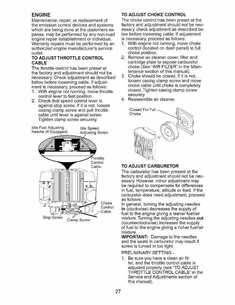
Maintenance, repair, or replacement ofthe emission control devices and systems,which are being done at the customers ex-pense, may be performed by any non-roadengine repair establishment or individual.Warranty repairs must be performed by anauthorized engine manufacturer's serviceoutlet.TO ADJUST THROTTLE CONTROLCABLE
The throttle control has been preset atthe factory and adjustment should not benecessary. Check adjustment as describedbelow before loosening cable. If adjust-ment is necessary, proceed as follows:1. With engine not running, move throttle
control lever to fast position.2. Check that speed control lever is
against stop screw. If it is not, loosencasing clamp screw and pull throttlecable until lever is against screw.Tighten clamp screw securely.
Idle Fuel AdjustingNeedle (If Equip
Idle SpeedAdjusting Screw
_rottleControlCable
01_8
Stop ScrewClamp Screw
ChokeControlCable
TO ADJUST CHOKE CONTROL
The choke control has been preset at thefactory and adjustment should not be nec-essary, check adjustment as described be-low before loosening cable. If adjustmentis necessary, proceed as follows:1. With engine not running, move choke
control (located on dash panel) to fullchoke position.
2. Remove air cleaner cover, filter andcartridge plate to expose carburetorchoke (See "AIR FILTER" in the Main-tenance section of this manual).
3. Choke should be closed. If it is not,loosen casing clamp screw and movechoke cable until choke is completelyclosed. Tighten casing clamp screwsecurely.
4. Reassemble air cleaner.
Closed For Full
Choke _.
TO ADJUST CARBURETOR
The carburetor has been present at thefactory and adjustment should not be nec-essary. However, minor adjustment maybe required to compensate for differencesin fuel, temperature, altitude or load. If thecarburetor does need adjustment, proceedas follows:
In general, turning the adjusting needlesin (clockwise) decreases the supply offuel to the engine giving a leaner fuel/airmixture. Turning the adjusting needles out(counterclockwise) increases the supplyof fuel to the engine giving a richer fuel/airmixture.
IMPORTANT: Damage to the needlesand the seats in carburetor may result ifscrew is turned in too tight.
PRELIMINARY SETTING -
1. Be sure you have a clean air fil-ter, and the throttle control cable isadjusted properly (see "TO ADJUSTTHROTTLE CONTROL CABLE" in theService and Adjustments section ofthis manual).
27

1 With engine off turn idle fuel adjust-ing needle in (clockwise) closing itfinger tight and then turn out (counter-clockwise) 1 turn.
FINAL SETTING -
1. Start engine and allow to warm for fiveminutes. Make final adjustments withengine running and shift/motion controllever in neutral (N) position.
NOTE: The high idle is set at the factoryand cannot be adjusted.2. Idle speed setting - With throttle control
lever in slow position, engine shouldidle at 1750 RPM. If engine idles tooslow or fast, turn idle speed adjustingscrew in or out until correct idle is at-tained.
3. Idle fuel needle setting - With throttlecontrol lever in slow position, turn idlefuel adjusting needle in (clockwise)until engine speed decreases and thenturn out (counterclockwise) approxi-mately 3/4 turn to obtain the best lowspeed performance.
4. Recheck idle speed. Readjust if neces-sary.
ACCELERATION TEST -
5. Move throttle control lever from slow
to fast position. If engine hesitates ordies, turn idle fuel adjusting needle out(counterclockwise) 1/8 turn. Repeattest and continue to adjust, if neces-sary, until engine accelerates smoothly.
High speed stop is factory adjusted. Donot adjust-damage may result.
IMPORTANT: Never tamper with theengine governor, which is factory setfor proper engine speed. Overspeedingthe engine above the factory high speedsetting can be dangerous. If you think theengine-governed high speed needs ad-justing, contact a Sears or other qualifiedservice center, which has proper equip-ment and experience to make any neces-sary adjustments.
28

Immediately prepare your tractor for stor-age at the end of the season or if the trac-tor will not be used for 30 days or more.
WARNING: Never store the tractor
with gasoline in the tank inside a buildingwhere fumes may reach an open flameor spark. Allow the engine to cool beforestoring in any enclosure.
TRACTOR
Remove mower from tractor for winterstorage. When mower is to be stored for aperiod of time, clean it thoroughly, removeall dirt, grease, leaves, etc. Store in aclean, dry area.1. Clean entire tractor (See "CLEANING"
in the Maintenance section of this
manual).2. Inspect and replace belts, if necessary
(See belt replacement instructions inthe Service and Adjustments section ofthis manual).
3. Lubricate as shown in the Maintenancesection of this manual.
4. Be sure that all nuts, bolts and screwsare securely fastened. Inspect movingparts for damage, breakage and wear.Replace if necessary.
5. Touch up all rusted or chipped paintsurfaces; sand lightly before painting.
BATTERY
• Fully charge the battery for storage.• After a period of time in storage, battery
may require recharging.• To help prevent corrosion and power
leakage during long periods of storage,battery cables should be disconnectedand battery cleaned thoroughly (see "TOCLEAN BATTERY AND TERMINALS" in
the Maintenance section of this manual).• After cleaning, leave cables discon-
nected and place cables where theycannot come in contact with batteryterminals.
• If battery is removed from tractor forstorage, do not store battery directly onconcrete or damp surfaces.
ENGINE
FUEL SYSTEM
IMPORTANT: It is important to preventgum deposites from forming in essentialfuel system parts such as carburetor, fuelhose, or tank during storage. Also, experi-
ance indicates that alcohol blended fuels
(called gasohol or using ethanol or metha-nol) can attract moisture which leads toseparation and formation of acids duringstorage. Acidic gas can damage the fuelsystem of an engine while in storage.• Empty the fuel tank by starting the en-
gine and letting it run until the fuel linesand carburetor are empty.
• Never use engine or carburetor cleanerproducts in the fuel tank or permanentdamage may occur.
• Use fresh fuel next season.
NOTE: Fuel stabilizer is an acceptablealternative in minimizing the formation offuel gum deposits during storage. Addstabilizer to gasoline in fuel tank or stor-age container. Always follow the mix ratiofound on stabilizer container. Run engineat least 10 minutes after adding stabilizerto allow the stabilizer to reach the car-
buretor. Do not empty the gas tank andcarburetor if using fuel stabilizer.ENGINE OIL
Drain oil (with engine warm) and replacewith clean engine oil. (See "ENGINE" inthe Maintenance section of this manual).CYLINDER(S)
1. Remove spark plug(s).2. Pour one ounce of oil through spark
plug hole(s)into cylinder(s).3. Turn ignition key to "START" position
for a few seconds to distribute oil.
4. Replace with new spark plug(s).
OTHER
• Do not store gasoline from one seasonto another.
• Replace your gasoline can if your canstarts to rust. Rust and/or dirt in yourgasoline will cause problems.
• If possible, store your tractor indoorsand cover it to give protection from dustand dirt.
• Cover your tractor with a suitable pro-tective cover that does not retain mois-
ture. Do not use plastic. Plastic cannotbreathe which allows condensation to
form and will cause your tractor to rust.IMPORTANT: Never cover tractor while
engine and exhaust areas are still warm.
29

TROUBLESHOOTING CHART:See appropriate section in manual unless directed to Sears service centerPROBLEM CAUSE CORRECTION
Will not start
Hard to start
Engine will notturn over
1. Out of fuel.
2. Engine not "CHOKED"properly.
3. Engine flooded.
Engine clicks butwill not start
4. Bad spark plug.5. Dirty air filter.6. Dirty fuel filter.7. Water in fuel.
8. Loose or damaged wiring.9. Carburetor out of
adjustment.
10. Engine valves out ofadjustment.
11. Extreme Cold Conditions
1. Dirty air filter.2. Bad spark plug.3. Weak or dead battery.4. Dirty fuel filter.5. Stale or dirty fuel.
6. Loose or damaged wiring.7. Carburetor out of
adjustment.
8. Engine valves out ofadjustment.
1. Brake pedal notdepressed
2. Attachment clutch is
engaged.3. Weak or dead battery.4. Blown fuse.
5. Corroded battery terminals.6. Loose or damaged wiring.7. Faulty ignition switch.
8. Faulty solenoid or starter.
9. Faulty operator presenceswitch(es).
1. Weak or dead battery.2. Corroded battery terminals.3. Loose or damaged wiring.4. Faulty solenoid or starter.
1. Fill fuel tank.2. See "TO START ENGINE"
in Operation section.3. Wait several minutes before
attempting to start.4. Replace spark plug.5. Clean/replace air filter.6. Replace fuel filter.7. Empty fuel tank and carbure-
tor, refill tank with freshgasoline and replace fuelfilter.
8. Check all wiring.9. See "To Adjust Carburetor"
in Service and Adjustmentssection.
10. Contact a Sears or other
qualified service center.11. See "To start engine" in
operation section.
1. Clean/replace air filter.2. Replace spark plug.3. Recharge or replace battery.4. Replace fuel filter.5. Empty fuel tank and refill tank
with fresh, clean gasoline.6. Check all wiring.7. See "To Adjust Carburetor"
in Service and Adjustmentssection.
8. Contact a Sears or otherqualified service center.
1. Depress brake pedal.
2. Disengage attachmentclutch.
3. Recharge or replace battery.4. Replace fuse.5. Clean battery terminals.6. Check all wiring.7. Check/replace ignition
switch.
8. Check/replace solenoid orstarter.
9. Contact a Sears or other
qualified service center.
1. Recharge or replace battery.2. Clean battery terminals.3. Check all wiring.4. Check/replace solenoid or
starter.
30

TROUBLESHOOTING CHART:
See appropriate section in manual unless directed to Sears service center
PROBLEM CAUSE CORRECTION
Loss of power 1. Cutting too much grass/too 1. Raise cutting height/reducefast. speed.
2. Throttle in "CHOKE" 2. Adjust throttle control.position.
3. Build-up of grass, leaves 3. Clean underside of mowerand trash under mower, housing.
4. Dirty air filter. 4. Clean/replace air filter.5. Low oil level/dirty oil. 5. Check oil level/change oil.6. Faulty spark plug. 6. Clean and regap or change
spark plug.7. Dirty fuel filter. 7. Replace fuel filter.8. Stale or dirty fuel. 8. Empty fuel tank and refill tank
with fresh, clean gasoline.9. Water in fuel. 9. Empty fuel tank and
carburetor, refill tank withfresh gasoline and replacefuel filter.
10. Spark plug wire loose. 10. Connect and tighten sparkplug wire.
11. Dirty engine air screen/fins. 11. Clean engine air screen/fins.
12. Dirty/clogged muffler. 12. Clean/replace muffler.13. Loose or damaged wiring. 13. Check all wiring.14. Carburetor out of 14. See "To Adjust Carburetor"
adjustment, in Service and Adjustmentssection.
15. Engine valves out of 15. Contact a Sears or otheradjustment, qualified service center.
Excessive 1. Worn, bent or loose blade. 1. Replace blade.vibration Tighten blade bolt.
2. Bent blade mandrel. 2. Contact a Sears or other
Engine continuesto run when
operator leavesseat withattachment
clutch engaged
Poor cut - uneven
3. Loose/damaged part(s).
. Faulty operator-safetypresence control system.
1. Worn, bent or loose blade.
.
.
.
qualified service center.Tighten loose part(s).Replace damaged parts.
Check wiring, switches andconnections. If not corrected,contact a Sears or otherqualified service center.
Replace blade. Tightenblade bolt.
2. Mower deck not level.
3. Buildup of grass, leaves,and trash under mower.
4. Bent blade mandrel.
. Clogged mower deck ventfrom build-up of grass,leaves, and trash aroundmandrels.
2. Level mower deck.3. Clean underside of mower
housing.4. Contact a Sears or other
qualified service center.5. Clean around mandrels to
open vent holes.
31
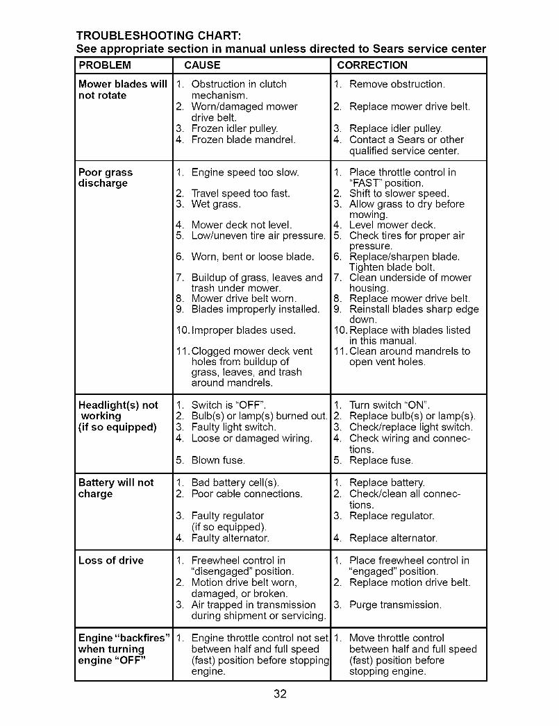
TROUBLESHOOTING CHART:See appropriate section in manual unless directed to Sears service centerPROBLEM CAUSE
Mower blades willnot rotate
Poor grassdischarge
Headlight(s) notworking(if so equipped)
Battery will notcharge
Loss of drive
Engine "backfires"when turningengine "OFF"
1. Obstruction in clutchmechanism.
2. Worn/damaged mowerdrive belt.
3. Frozen idler pulley.4. Frozen blade mandrel.
1. Engine speed too slow.
2. Travel speed too fast.3. Wet grass.
4. Mower deck not level.5. Low/uneven tire air pressure.
6. Worn, bent or loose blade.
7. Buildup of grass, leaves andtrash under mower.
8. Mower drive belt worn.9. Blades improperly installed.
10. Improper blades used.
11. Clogged mower deck ventholes from buildup ofgrass, leaves, and trasharound mandrels.
1. Switch is "OFF".
2. Bulb(s) or lamp(s) burned out.3. Faulty light switch.4. Loose or damaged wiring.
5. Blown fuse.
1. Bad battery cell(s).2. Poor cable connections.
3. Faulty regulator(if so equipped).
4. Faulty alternator.
1. Freewheel control in"disengaged" position.
2. Motion drive belt worn,damaged, or broken.
3. Air trapped in transmissionduring shipment or servicing.
. Engine throttle control not setbetween half and full speed(fast) position before stoppingengine.
CORRECTION
1. Remove obstruction.
2. Replace mower drive belt.
3. Replace idler pulley.4. Contact a Sears or other
qualified service center.
1. Place throttle control in"FAST" position.
2. Shift to slower speed.3. Allow grass to dry before
mowing.4. Level mower deck.5. Check tires for proper air
pressure.6. Replace/sharpen blade.
Tighten blade bolt.7. Clean underside of mower
housing.8. Replace mower drive belt.9. Reinstall blades sharp edge
down.10. Replace with blades listed
in this manual.11. Clean around mandrels to
open vent holes.
1. Turn switch "ON".
2. Replace bulb(s) or lamp(s).3. Check/replace light switch.4. Check wiring and connec-
tions.
5. Replace fuse.
1. Replace battery.2. Check/clean all connec-
tions.3. Replace regulator.
4. Replace alternator.
1. Place freewheel control in"engaged" position.
2. Replace motion drive belt.
3. Purge transmission.
. Move throttle control
between half and full speed(fast) position beforestopping engine.
32

SCHEMATICTRACTOR -- MODEL NUMBER 917.276022
RED
AMMETER
(OPTIONAL)
RED
BATTERY
RED _
FUSE
WHITE
BLACK
RED
SOLENOID
I
I
I J
STARTER
BLACK
BLACK
)G
I
I
B
F H
©
D
PTO (DISENGAGED)
IELECTRIC CLUTCH
I
I I
CLUTCH / BRAKE I •(PEDAL UP)
RED
BLUE
FUEL i
--Ii ............._/_LINE II
I I
ICHARGING SYSTEM OUTPUT
FUEL SHUT-OFF _5AMPoc @36O0RPM
SOLENOID _// I
................................. REGULATOR
SEAT SWITCH(NOT OCCUPIED)
I I
I
• I
GROUNDING
(_ CONNECTOR
............................9-A2_....................................................................................................................................................SPARK PLUGS
IGNITION _ GAP
--[ UNIT _ ON TVVI_ _E°N GIN ES)
28 VOLTS AC @ 3600 RPM
/ (REGULATOR DISCONNECTED
ALTERNATOR ]
IGNITION SWITCH
POSITION CIRCUIT "MAKE"
OFF M+G+A1 NONE
ON+LIGHTS B+A1 L+A2
ON B + A1 NONE
START B+S+A1 NONE
HEADLIGHTS
WIRING INSULATED CLIPS
NOTE: IF WIRING INSULATEDCLIPS WERE REMOVED FOR
SERVICING OF UNIT, THEYSHOULD BE REPLACED TOPROPERLY SECURE YOURWIRING.
©REMOVABLE
02742 CONNECTIONS
PTO SWITCH
I POSITION CIRCUIT
I OFF C+G,B+HON C+F,B+E,A+D
NON-REMOVABLECONNECTIONS
GFC
DA
PTO SWITCHCONNECTOR
33

ELECTRICALTRACTOR -- MODEL NUMBER 917.276022
i_ 11 1_
I \1
I 27
12
33
34

ELECTRICALTRACTOR -- MODEL NUMBER 917.276022
KEY PARTNO. NO. DESCRIPTION
1 144927 Battery2 74760412 Bolt Hex Head 1/4-20 x 3/4
8 7603J Tray, Battery10 145211 Bolt 1/4-20 x 7.5 Zinc
11 150109 Hold down Battery Dash Mount12 145769 Nut Push Nylon 1/4"16 176138 Switch Interlock Push-In
21 175688 Harness Socket Light W/4152J22 4152J Bulb Light25 185456 Cable, Battery26 108824X Fuse
27 73510400 Nut Keps Hex 1/4-20 uric28 170697 Cable, Ground29 121305X Switch, Plunger30 175566 Switch, Ign33 140403 Key, Ignition40 188032 Harness Ign.42 154336 Cover, Terminal45 122822X Ammeter
50 174652 Switch, PTO52 141940 Hourmeter Adaptor79 175242 Bulbholder Asm incandescent SV81 109748X Relay Asm.
NOTE: All component dimensions given in U. S.inches 1 inch = 25.4 mm
35

TRACTOR -- MODEL NUMBER 917,276022CHASSIS AND ENCLOSURES
138
151
158
37
122
150
122
153
21
I
_o19
2
\
56
86
.156
6
chassis-stealth_43-vgt
36

TRACTOR -- MODEL NUMBER 917,276022CHASSIS AND ENCLOSURES
KEY PARTNO. NO. DESCRIPTION
1 180375 Rail, Frame RH2 175282 Drawbar, Gt4 73680700 Nut 7/16-145 187934X428 Dash
6 157882 Dash, Lower Vgt One Piece7 17720408 Screw, Thd Cut 1/4-20 x 1/28 184668 Support, Battery14 175260X615 Hood Asm16 121794X Cover, Access17 17000612 Screw 3/8-16 x .7518 174515X615 Grille19 19131312 Washer 13/32x13/16 x 12 Ga.20 STD523710 Bolt, Fin Hex 3/8-16 x 121 STD541437 Nut Crownlock 3/8-16 unc24 179717X615 Footrest, RH28 179716X615 Footrest, LH30 145052 Saddle, Hydro31 161419 Brace, Supt 1-pcVGT32 161327 Bracket, Pivot Chassis Lh33 161326 Bracket, Pivot Chassis Rh34 177018 Plate Asm Engine35 19111116 Washer 11/32 x 11/16 x 16 Ga.36 17060512 Screw 5116-18 x 31437 178510X615 Fender Pnt39 175278 Bracket, Axle Front43 136939 Bracket, Spnsn Front Lh44 136940 Bracket, Spnsn Front Rh45 176018 Bracket Asm., Susp Chas.Rh47 17490608 ScrewThdrol. 3/8-16 x 1/2
50 175476 Bracket, Chassis Front56 176016 Bracket Asm., Susp Chas. Lh58 183569 Bracket Asm., Fender68 17490508 ScrewThdrol. 5/16-18 x 1/286 74780616 Bolt Fin Hex 7/16-14 uric x 191 180374 Rail, Frame Lh99 177143 Rod By Pass122 161464 Screw Hex Wshd 8-18 x 7/8130 171875 Screw Hwhd Hi-Lo #13-16 x 3/4138 179125X428 Cup Holder139 171873 Bolt Shoulder 5/16-18 TT142 161897 Bracket Dash Rh144 161900 Bracket Dash Lh148 164655 Extrusion Bumpers150 175352 Duct Heat Hood152 177956 Shield Browning153 179761 Lightbox Asm WlLens156 17000512 Screw 5t16-18 x 3/4157 161840 Lens Bar158 17670608 Screw Thdrol 3/8-16 x 1/2161 179612X428 Console Fuel Window162 142432 Screw Hex 1/4-1/2 uric
165 183554 Bracket Support Tank
NOTE: All component dimensions given in U. S.inches 1 inch = 25.4 mm
37

TRACTOR -- MODEL NUMBER 917.276022GROUND DRIVE
9
69
33
drive 6-vgt
127 148
35
34
46
68
151
<.
64 37 38 5 i
.;_" /p °,
13377 .148
111
114_- 23 f_ --..,,_._× 148
112
38

TRACTOR -- MODEL NUMBER 917.276022GROUND DRIVE
KEY PART KEY PARTNO. NO. DESCRIPTION NO. NO. DESCRIPTION
1 Transaxle Hydro Gear 94 133835331-3000 (See Breakdown) 98 141004
2 7070E Key 1/4 x 2.5 106 1429183 7563R Washer Thrust 107 154739
6 STD561210 Pin, Cotter 108 1429177 140507 Wheel, Hub Assembly 111 1562409 140080 Bolt, Hub 112 17855820 73940800 Nut 114 7380050022 180235 Lever Asm Shift Lower 117 7390060023 130564 Knob 120 1700061229 176600 Brake, Rod 121 17561133 12000053 Ring E 122 7201052034 71673 Cap, Parking Brake35 137648 Rod, Parking Brake 123 18325436 149412 Spring, Drive Ground 124 16549237 121749X Washer 25t32 x 1-1/4 x 16 Ga. 125 17490510
38 150035 Nyliner 126 16600239 74321016 Screw, Fin. #10-24 x 140 178575 Actuator, Interlock Switch 127 17736241 73931000 Nut Centerlock 10-24 unc 128 17662442 8883R Cover, Pedal 129 17947346 145170 Retainer, Spring 130 1913101648 72110614 Bolt, 318-16 x 1-3/4 Gr. 5 131 7602031250 131494 Pulley, Idler, Flat 132 17546752 127783 Pulley, Idler, Grooved 133 17546855 105706X Bearing, Idler 135 17736456 161597 V-Belt 137 1685H58 74760724 Bolt Fin Hex 7/16-14 x 1-1/2 138 1370H
61 143995 Pulley, Transaxle 142 17546964 176601 Shaft, Clutch/Brake Pedal 143 1700051265 179613 Bolt, Shoulder 145 16316868 STD571812 Pin, Roll 146 14046269 123800X Washer 147 14132270 179121X428 Console AutomaticYT/GT 151 74760514
73 74490548 Bolt Hex Flghd 5/16-18 x 3 Gr. 5 152 17870574 142432 Screw HexWsh. Hi-Lo 1/4-1/2 153 4997H77 74780720 Bolt Hex 7/16-14 x 1-1/4 Gr. 589 73680700 Nut Crownlock 7/16-14 unc
Fastener Christmas TreeBracket Shift
O-Ring Asm Hydro GearLine Fuel Hydro 15" VGTCap Asm Vent Hydro Gear 70109Spacer Shift Lever VGTHWasher Nylon High TempNut Lock Hx W/Ins 5/16-18 uric
Nut, Lock Fig. 3/8-16Screw 3/8-16 x .75
Bracket Strap TorqueBolt RDHD SQ5/16-18 unc x 2-1/2Rod ShiftBolt Shoulder 5/16-18 x .561Screw 5/16-18 x 5t8Washer SRRTD51161D x 1.0 x .125Link Control ClutchSpring Drive GRNDBracket Asm Idler TensioningWasher 13/32 x 5/8 x 16 Ga.Pin Cotter 3/32 x 3/4Bracket Mtg Hydro 3500 LH VGTBracket Mtg Hydro 3500 RH VGTLink Asm Control Hydro 3500Nut Lock 5/16-18 NC ThdWasher Thrust 5/8 x 1.10 x 1/32
Strap Torque HG-3500Screw Thdrol 5/16-18 x 3t4
Washer Axle Flange HG-3000Fan 7" HydroWasherBolt Fin Hex 5/16-18 x 7/8Bolt Hex 5116-18 x 1Retainer Spring
NOTE: All component dimensions given in U. S.inches 1 inch = 25.4 mm
39

STEERINGTRACTOR -- MODEL NUMBER 917,276022
23
34
33
32
6
<"
42
//
22
13
/31
\
16
29
36
\\,
<28
49
0
I j-
15
1313
/ i \
i I i I 1
I I III
\ I
J
18_ steering 13-vgt
J
40

STEERINGTRACTOR -- MODEL NUMBER 917,276022
KEY PARTNO. NO. DESCRIPTION
1 159944X4282 1785573 1832264 1618495 1618486 6266H7 121748X8 120000299 184946X50510 7478104411 13651812 7390100013 121749X14 STD55113715 STD54153716 18681418 17557219 15601120 163887X42821 15994522 15510523 15292726 159946X42827 3366R28 1700061229 104239X31 13813632 1911161033 STD55113134 7478051235 18703936 18679941 15524642 1749050844 160135X42845 1918241146 1913161047 17947149 17582050 7390060051 7394080052 17555353 188967
Wheel, SteeringAxle Asm., FrontFitting, GreaseSpindle Asm, LHSpindle Asm., RHBearing, Race Thrust HardenWasher 25/32 x 1-5/8 x 16 Ga.
Ring, Klip #T5304-75Cap, SpindleBolt, Fin Hex 5/8-11 x 2-3/4Spacer Bearing Axle FrontNut, Lock Flange 5/8-11 uncWasher 25/32 x 1-1/4 x 16 Ga.
Washer, Lock Hvy HIcl Spr 3/8Nut, Lock Center 3/8-24 unfShaft Asm., SteeringDraglink VgtSupport Asm., Steering VgtBoot, SteeringAdapter, Wheel SteeringBushing, Strg. BIkScrew
Cap, Wheel SteeringBearing, Col. Strg.Screw, 318-16 x 3/4Bearing, FlangeBushing, Nyliner SnapWasher 11/32xlx10Ga.
Washer, Lock Hvy Hlcl Spr 5t16Bolt Fin Hex 5116-18 unc x 314
Gear, Sector SteeringTie RodBracket Switch Interlock VGT 97ScrewThdrol 5116-18 x 112 TytExtension, SteeringWasher 9/16 x 1-1/20 x 11 Ga.Washer Flat 13/32 x 1 x 10 Ga.Bracket Asm Idler StationaryPulley Idler FlatNut Lock Fig 3/8-16 uncNut Hex Jam Toplock 1/2-20 unfClip Steering .750Washer Hardened
NOTE: All component dimensions given in U. S.inches 1 inch = 25.4 mm
41

ENGINETRACTOR -- MODEL NUMBER 917,276022
18
26
engine-kohber22_17-vgt
15
27
2O
37
28
39
85
9
8
40
84
12
11
82
69
n
7OI n
_86I
29
SPARK ARRESTER KIT
KEY PARTNO. NO.
1
2 1497238 121361X9 17774810 17528711 17933512 14399615 17911518 179124X42820 177328X42821 17187522 187768X42824 STD55123726 3645J27 13927728 7834R29 13718037 123487X
DESCRIPTION
Engine (See Breakdown)Kohler Model No. CV730-0029Muffler
Pulley V-IdlerKeeper Asm. Belt EngineBushingClutch Electric
Pulley Engine VGT Elect ClutchTank Fuel Rear 5.0 Yt/Gt 96
Cap Asm Fuel W/GaugeControl ThrottleScrew hwhd Hi-Lo #13-16 x 3/4Control ChokeWasher Ext Tooth 3/8BushingStern Tank FuelFuel Line
Spark Arrester KitClamp Hose
KEY PART
NO. NO. DESCRIPTION
39 17490636 ScrewTT 3/8-16 x 2-1/4 uric40 17490664 Screw TT 3/8-16 x 4 unc41 126197X Washer
1-1/20D x 15/32 ID x .25042 STD551143 Washer Lock 7/16
47 175288 Spacer Engine62 146629 Shield Heat Muffler69 24-041-49 Gasket70 175545 Tube Exhaust LH71 175546 Tube Exhaust RH80 M73030800 Nut Flange81 188800 Tube Drain Oil82 188799 Valve Oil Drain83 171877 Bolt 5/16-18 unc x 31484 17060624 Screw 318-16 x 1-1/285 179953 Bolt Hex 7/16 - 20 x 3.75 Gr. 586 184362 Nut Hex Flange Toplock M8-1.25
NOTE: All component dimensions given in U. S.inches 1 inch = 25.4 mm
42

TRACTOR -- MODEL NUMBER 917,276022SEAT ASSEMBLY
17
KEY PARTNO. NO.
1 1805982 1801663 1406755 1450066 STD5414377 124181X8 17187710 18018612 121246X13 121248X14 72050412
18
19
12
5
10
I
II
%37
21
seat12-vgt
KEYDESCRIPTION NO.
Seat 15Bracket, Pivot Seat 16Strap, Fender Assembly 17Clip, Push In, Hinged 18Nut, Crownlock 3/8-16 unc 19Spring, Seat Cprsn 20Bolt 5/16-18 unc x 3/4 w/Sems 21Pan, Seat 37Bracket, Mounting SwitchBushing, SnapBolt, Carriage 1/4-20 x 1-1/2
PART
NO. DESCRIPTION
121249X Spacer, Split123740X Spring, Cprsn123976X Nut, Lock 1/4 Lge Fig Gr. 519171912 Washer 17t32 x 1-3t16 x 12 Ga.166369 Knob, Seat124238X Cap, Spring Seat171852 Bolt, Shoulder 5/16-1873800500 Nut, Lock Hx w/Ins. 5/16-18
NOTE: All component dimensions given in U. S.inches 1 inch = 25.4 mm
43

DECALSTRACTOR -- MODEL NUMBER 917,276022
1718 3
15 15
17
10
13
8
2225
26
14 23
12
KEY PARTNO. NO.
1 1640942 149516
3 1862424 1862435 1408376 1336447 1859808 1779189 18657210 15643911 18125212 17755413 18640314 17529115 186725
WHEELS
2
2O 11
DESCRIPTION
Decal DashDecal Battery DNGR/PSNENG AsmDecal Hood RHDecal Hood LHDecal Brake Parking SaddleDecal MaintenanceDecal EngineDecal EngineDecal Fender
Decal Fender DangerDecal FTRESTDecal V-Belt Dr SchDecal ReplacementDecal V-Belt SchemDecal Hood Side Pnl
AND TIRES
47 10
59
\
16
KEY PART
NO. NO. DESCRIPTION
16 178482 Decal Deck HVYDTY17 177665 Decal Dash Panel18 164065 Decal Insert Strg19 138047 Decal Battery20 181470 Decal Deck Level
22 177914 Decal Engine Logo23 106202X Reflector, Taillight25 177917 Decal Engine LH26 177916 Decal Engine RH- - 179768X428 Pad Footrest LH- - 166960 Decal Drawbar CNTRL- - 179769X428 Pad Footrest RH- - 191267 Owner's Manual, English- - 191268 Owner's Manual, Spanish
KEY PARTNO. NO. DESCRIPTION
1 59192 Cap Valve Tire2 65139 Stem Valve3 106228X624 Rim Asm Front4 8134H Tube, Front (Service Item Only)5 105588X Tire, Front6 278H Fitting Grease (Front Wheel Only)7 9040H Bearing Flange(Front Wheel Only)8 104757X428 Cap Axle (Front Wheel Only)9 106230X Tire Rear10 7154J Tube Rear (Service Item Only)11 106277X624 Rim Asm Rear12 6856M Fitting Grease- - 144334 Sealant, Tire ( 10 oz. Tube)
NOTE: All component dimensions given in U. S.inches 1 inch = 25.4 mm
44

TRACTOR -- MODEL NUMBER 917.276022LIFT ASSEMBLY
23
lO /\
7o
KEYNO.
12345678lO1112232426293031323334
PARTNO,
121006X180045159189120000221929201671110624175830175831X505183894175375163552STD6240087335080073680800150233110807XSTD551037137150STD560907137167
lift rh 8
DESCRIPTIONKEY PARTNO. NO. DESCRIPTION
Rod Asm., LeverShaft Asm., Lift VgtLever Asm., Lift RhE-Ring Truarc #5133-87Washer 29132 x 1-114 x 16 Ga.Bolt, Fin Hex 3/8-16 x 1-1/2Grip, Handle FlutedPlunger, ButtonSpringLink Lift
Retainer SpringRetainer, SpringNut, Jam Hex 112-13 uncNut Crownlock 1/2-13 unc
Trunnion, Infin HeightNut, SpecialWasher 13132 x 5t8 x 16 Ga.Spring, Compression Inf HgtPin, Cotter 3/32 x 1/2Rod, Adj Lift
35 138057 Knob, Inf 3/8-16 unc38 155097 Pointer, Height Indicator39 123935X Plug, Hole40 17060516 Screw Hex Wsh 5t16-18 x 1
41 175994 Nut, Lift Link 7/16-2042 19112410 Washer 11/32 x 1-1/2 x 10 Ga.
43 123934X Scale, Indicator Height70 145212 Nut Hex Flange Lock72 110452X Nut Push Phos & Oil73 73350600 Nut Hex Jam 3/8-16 unc
74 175802 Arm Susp. Rear RH75 175805 Plate Asm. Susp. Front76 175560 Pin, Flange77 176205 Trunnion Susp. Arm78 175689 Trunnion Susp. Front79 175378 Arm, susp. R LH
NOTE: All component dimensions given in U. S.inches 1 inch = 25.4 mm
45

TRACTOR -- MODEL NUMBER 917,276022MOWER DECK
46
_(,49
I 52 _49
3
130
3 I
121 42!
46
I97'
21
I
47
/
26
18
mower_deck.481owcost_stlt_2
46

TRACTOR -- MODEL NUMBER 917,276022MOWER DECK
KEY PART KEY PARTNO. NO. DESCRIPTION NO. NO. DESCRIPTION
1 180358 Deck Weldment 42 165723
3 178915 Bracket Asm., Sway Bar 43 1743735 4939M Retainer Spring 45 1808066 178024 Arm, Suspension, Rear 46 137729
(Sway Bar) 47 1808088 174365 Bolt 7/16 Asm. Blade 48 174368
(The following blades are avail 49 73900600able) 50 72110612
11 180054 Blade, 48" Hi-lift 52 175820(For bagging and discharging) 56 155986
- - 173921 Blade, 48" Mulching 57 156941(For mulching mowers only) 97 178515
13 174360 Shaft Asm. w/Lower Bearing 98 17947914 174358 Housing Mandrel 99 18405815 110485X Bearing, Ball, Mandrel 100 7211061616 174493 Stripper Mandrel Deck 110 17501617 72110610 Bolt RDHD Sq Neck 3/8-16 x 1.25 111 17461018 72140505 Bolt, Carriage 5/16-18 x 5/8 113 7211050619 132827 Bolt, Hex Hd, Shoulder 5/16-18 116 18421920 174378 Baffle, Vortex Mower 117 17487321 73680500 Nut, Crownlock 5/16-18 unc 118 7393060024 105304X Cap, Sleeve 119 1912141425 178102 Spring, Torsion 121 17437126 110452X Nut, Push 126 17437227 180655X428 Deflector Shield 130 1700061628 19111016 Washer 11/32 x 5/8 x 16 Ga. 131 1913160629 131491 Rod, Hinge 184 17397930 173984 Screw, Thdroll - - 17435631 187690 Washer, Spacer Mower Vented32 174346 Pulley, Mandrel -- 18635333 178342 Nut, Fig. Top Lock Cntr. 9/1637 177968 Pulley, Idler, 48" Primary39 174375 Pulley, Idler, Driven
Spacer, RetainerArm, Idler SecondaryCover, Mandrel DeckScrew, Thdroll. 1/4-20 x 5t8V-Belt, Mower, SecondaryV-Belt, Mower, PrimaryNut 3/8-16 unc
Bolt, Carr. 3/8-16 x 1-1/2 Gr. 5Pulley Idler FlatBar Pnt Adj.Pin Head RivetWasher HardenedSpring Primary DrivePulley Idler"V"Bolt RDHD Sqnk 3/8-16 uric x 2Arm Spring SecondaryArm Spring Fixed TensionBolt 5/16-18 x 3/4Bolt, ShoulderGauge WheelNut, Centerlock 318-16 uncWasher 3/8 x 7/8 x 14 Ga.Spring Secondary DriveArm, idler, Primary DeckScrew 3/8-16 x 1.0.BIkWasher 13t32 x 114 x 16 Ga.Keeper Belt IdlerMandrel Asm. Service (IncludesKey Nos. 13-15)Replacement Mower, Complete
NOTE: All component dimensions given in U. S.inches 1 inch = 25.4 mm
47

TRACTOR -- MODEL NUMBER 917,276022TRANSAXLE--MODEL NUMBER 331-3000
]i
/57
_53
...............52
--54
/62
J
_!41
48

TRACTOR -- MODEL NUMBER 917.276022TRANSAXLE--MODEL NUMBER 331-3000
KEY PART KEY PARTNO. NO. DESCRIPTION NO. NO. DESCRIPTION
1 161122 Main Housing Assembly 74 1695352 178317 R.H. Housing Assembly 75 1611573 169522 Center Section Assembly 76 1611534 161125 Spacer 77 1428845 142932 Seal-Lip 79 1783226 142928 Wire Retaining Ring 80 1611597 142933 Retaining Ring 81 1611608 142934 Ball Bearing 82 1611619 169523 Cradle Bearing 83 16116210 169524 Variable Swashplate 84 16116311 150771 Thrust Bearing 30 X 52 X 13 85 16116412 161126 input Shaft 87 17832313 142978 Block Thrust Washer 88 17832414 142977 Arm - Trunnion 89 17832515 169050 10cc Cylinder Block Assembly 90 17832621 169525 21cc Cylinder Block Assembly 91 16953624 161127 Output (Motor) Shaft 92 17832725 169526 Thrust Bearing 42 X 68 X 16 93 14296926 161128 Control Arm 94 14298027 161129 Spacer 95 16953728 161130 16t Pinion Gear 96 16953829 169527 Capscrew, M6 X 1-22 97 15079830 142941 Slot Guide 106 16116631 161132 Trunnion Arm 108 17832832 161133 Trunnion Bushing 110 14291833 142940 Lip Seal 111 14291734 178318 Arm Return 116 16953935 178319 Arm Actuating 117 16116836 169528 5/16-24 Stud 120 14288337 142967 Puck, Friction 121 16954038 150787 Bypass Plate 122 17832939 169529 Bypass Actuator 124 17833040 142945 Lip Seal 125 14288741 142952 Bypass Arm 126 16117242 142953 Retaining Ring 127 16117343 142965 Pin 128 14288544 150797 Screw 129 14288648 178320 Puck 130 16117450 178343 Screw-Self Tapping 131 14288251 169530 Lower Cover 132 16954452 169531 Gerotor Assembly 134 17833153 144581 O-Ring 136 17833254 161139 Gerotor Cover 137 17833355 178321 Filter 138 17833456 169533 Charge Manifold 139 16117657 161142 Retainer, Motor Bearing
58 161143 Pin, Carrier 141 17833559 161144 15t Planet Gear 144 16954560 161145 7t Spur Gear 145 16954661 161146 21t Sun Gear 146 16954762 161147 Planet Thrust Plate 151 16118163 161148 51t Ring Gear 152 17833664 161149 Planetary Carrier 153 14291465 161150 Miter Gear, Diff. (Splined) 155 17833766 161151 Miter Gear, Diff. 157 16954867 161152 Shaft, Differential 180 16954968 161153 Diff. Thrust Plate 203 17833869 169534 Flange Bearing 900 16677370 161154 Washer71 161155 Washer73 161156 Hex Jam Nut, 518-18
Ball Brg 6205-1Seal 1"ld X 2.0472" X 0.375"Shaft, AxleWasherGasket Material
Torx Head Screw, 5/16-18Needle Bearing (Sce1412)Washer2Retaining RingLip Seal (0.875i.D.X1.3o.D.X0.25Brake DiskWasherScrew 5t16-24
BearingSpacerOring, 0.070 X 0.239Screw
Spring, Friction PackSpacer, Friction PackHex Lock Nut 5116-24
Sleeve BearingOil
Spacer, TrunnionPlugFitting-O Ring Ass'yCap Vent Ass'yRetaining RingStd Hdls PinPuck, BrakeRib Neck Bolt, 2"Brake Yoke
Arm, BrakePins, BrakeLockwasher, 1/4"Nut, 1/4-20Nut, CastleCotter Pin
SpacerPuck Plate
Rib Neck Bolt, 3" 1SpringSpring ExtensionPin SpringBolt Self TappingWasher, 7/8od X 0.265id X 0.125Thk
Spring BrakeO Ring, 2.864 Id X 0.070 ThkSpring, ReliefBall, 7t16Comp. Spring, Brake Anti-DragBrake Pull Rod
Plug, Straight ThreadKit Fan
Screw O-RingManifold KitKit Seal
Transaxle, complete
NOTE: All component dimensions given in U.S. inches1 inch = 25.4 mm
49

TRACTOR -- MODEL NUMBER 917.276022KOHLER ENGINE-MODEL NUMBER CV730, TYPE NUMBER 0029
.'YLINDER HEAD, VALVE AND BREATHER I
28
271_
C:' 22
20--
O--19
@...18
15/°
10
23_.@ /25
2J_ __._/27
©
H/8
_J7 _
--14
15
_17
/1
12 _
j13
3
/
5O

TRACTOR -- MODEL NUMBER 917.276022KOHLER ENGINE-MODEL NUMBER CV730,TYPE NUMBER 0029
HEADNALVEIBREATHER CRANKCASE
KEY PART KEY PARTNO. NO. DESCRIPTION NO. NO. DESCRIPTION
24-032-01-S1. 24-033-03-S Kit, breather coverw/gasket 1.
(includes 2, 3) 2.2. 24-041-50-S Gasket, breather3. 24-096-87-S Cover, breather 3. 24-294-13-S4. M-645020-S Screw, hex. flange 4. 24-380-13-S
M6x1.0x20 (4) 5. 24-067-13-S5. 25 139 60-S Plug, hex. ctsk. 1/8' 24-067-14-S6. 25-351-01-S Lifter, valve (4) 6. 24-874-08-S7. 24-755-66-S Kit, valve train (Includes 8,
11, 12)8. 24-411-05-S9. 24-841-03-S
10. 24-318-72-S11. 25-186-01 -S12. 24-599-01 -S13. 12 086 16-S
14. 66-086-07-S
15. 24-755-141-S
16. 24-153-28-S17. M-651030-S
18. 24-445-01 -S19. 24-016-01-S
24-016-02-S20. 24-017-01-S
24-017-02-S21. 66-032-05-S22. 235011-S23. 24-089-02-S24. 12-173-01-S25. 12-755-03-S26. 24-318-69-S27. 24-755-142-S
Rod, push (4)Kit, cylinder head gasket (2)(Includes 13)Head assembly, #2 cylinderArm, rocker (4)Pivot, rocker arm (4)Screw, hex. flangeM10x1.5x90 (8)Screw, hex. flangeM6x1.0x34 (4)Kit, valve cover - plain(includes 16,17)O-RingScrew, hex. flangeM6x1.0x30 (4)Strap, liftingValve, exhaust (Std.) (2)Valve, exhaust (.25) (2)Valve, intake (Std.) (2)Valve, intake (.25) (2)Seal, valve stem (2)Retainer, spring (4)Spring, valve (4)Cap, valve spring (4)Kit, retainer (4)Head assembly, #1 cylinderKit, valve cover - breather(Includes 16,17,29)Grommet, rubberKit, breather separator(includes 29,31-34)Screw, hex. flangeM5x0.Sx16 (2)Strap, breatherBracket, breather separatorSpacerHose, breather
28. 25-313-03-S29. 24-755-57-S
30. M-545016-S
24-874-16-S24-874-20-S24-874-21-S
7. 24-108-05-S24-108-06-S24-108-07-S
8. 24-018-01-S9. 12-422-09-S
12-422-13-S12-422-07-S12-422-08-S12-422-10-S12-422-11 -S12-422-12-S
10. 24-012-16-S11. 52-139-09-S12. M-545010-S
13. 24-018-04-S14. 24-402-05-S15. 12-153-01-S16. 24-126-19-S17. 12-123-04-S18. M-545016-S
19. 12-153-02-S20. 24-038-04-S
21. 24-755-46-S22. 25 153 02-S23. 24-018-09-S24. M-931010-S25. 28-032-09-S26. 24-468-15-S27. 24-144-38-S
31. 24-445-02-S32. 24-126-44-S33. 24-112-12-S35. 24-326-55-S
Seal, front oilCrankcase (USE: Miniblock24 782 14)FittingPin, locating (6)Connecting Rod (Std.) (2)Connecting Rod (.25) (2)Piston wiring Set (Std.) (2)(Includes 7, 8)Piston wiRing Set (.08)Piston wiRing Set (.25)Piston wiRing Set (.50)Ring Set (Std. & .08) (2)Ring Set (.25)Ring Set (.50)Retainer, piston pin (4)Shim, camshaft (A.R.)Shim, camshaft (A.R.)Shim, camshaft (A.R.)Shim, camshaft (A.R.)Shim, camshaftShim, camshaft (A.R.)Shim, camshaft (A.R.)CamshaftPlug, cupScrew, hex. flangeM5x0.8xl 0 (2)Retainer, reed (2)Reed, breather (2)O-Ring, lower oil fill tubeBracket, oil fill tubeTube, oil fillScrew, hex. flangeM5x0.8xl 6O-Ring upper oil fill tubeDipstick assemb y (Includes21, 22)Kit oil fill cap (includes 22)O-Ring, dipst ckRing, retainerWasher, nylon (top)Seal, governor cross shaftWasher (bottom)Shaft, governor cross
NOTE: All component dimensions given in U.S.inches 1 inch = 25.4 mm
51

TRACTOR -- MODEL NUMBER 917.276022KOHLER ENGINE-MODEL NUMBER CV730, TYPE NUMBER 0029
IGNITION/ELECTRICAL I
1
19-_3
17- I
AIR INTAKE J
BLOWER HOUSING AND BAFFLESJ
7
6
17
3
\7
10_
\18
20
52

TRACTOR -- MODEL NUMBER 917.276022KOHLER ENGINE-MODEL NUMBER CV730, TYPE NUMBER 0029
IGNITION/ELECTRICAL BLOWER HOUSING & BAFFLES
KEY PART KEY PARTNO. NO. DESCRIPTION NO. NO. DESCRIPTION
1. 54-755-15-S Kit, grass screen 1. 24-027-114-S(Includes 2-4, & 24-113-18- 2. 24-100-01-SS) 3. M-551016-S
2. M-403025-S Screw, hex. cap M4x0.7x25(4) 4. M-545016-S
3. X-25-92-S Washer, plain 5/16" (4)4. 24-112-04-S Spacer, grass screen (4) 5. M-545020-S5. 25-086-47-S Bolt, shoulder M6x1.0x16 (4)6. 24-157-08-S Fan 6. M-645016-S7. 12-086-14-S Screw, hex. flange
M10x1.5x46 7. 24-146-16-S8. 12-468-03-S Washer, plain 3/8" 8. 24-146-20-S9. X-42-15-S Key 9. 24-063-39-S10. 24-025-01-S Flywheel11. 41-403-09-S Rectifier-regulator 10. 24-063-58-S12. X-25-92-S Washer, plain 3/16" (3)13. 24-086-18-S Screw, phillips hd. 11-16x7/8 11. M-545010-S
(2)14. 236602-S Connector (3 contact) 12. 24-063-14-S15. 12-132-02-S Spark Plug (2) 13. 24-063-60-S16. M-548025-S Screw, hex. cap M5x0.8x25
(2) NOT ILLUSTRATED17. 54-755-09-S Kit, 15 amp stator 24-096-85-S
(Includes 18) 25-086-91-S18. 24 126 71-S Bracket, stator wire 25-113-39-S19. 48-154-02-S Clip, cable20. X-25-63-S Washer, plain 1/4" AIR INTAKE/FILTRATION21. 24-584-01-S Module, ignition (2)22. M-545020-S Screw, hex flange M5x0.Sx20 KEY PART
(4) NO. NO.23. 235173-S Clip, cable
NOT ILLUSTRATED24-126-137-S Bracket, ground strap24-176-82-S Harness, wiring25-454-03-S Tie, wire (3)24-113-18-S Decal, grass screen
Housing, blower (Includes 2)Nut, plastic (2)Screw, hex. flangeM5x0.Sxl 6Screw, hex. flangeM5x0.Sxl 6 (3)Screw, hex. flangeM5x0.Sx20 (4)Screw, hex. flangeM6x1.0xl 6 (6)Plate, backing - # 2 sidePlate, backing - # 1 sideBaffle, cylinder barrel - # 2sideBaffle, cylinder barrel - # 1sideScrew, hex. flange
M5x0.Sxl 0 (2)Baffle, valley - #2 sideBaffle, valley - #1 side
Cover, blower housingScrew, tapping 10-16xl/2" (2)Decal, clear lamination
DESCRIPTION
1. 54-755-01-S Kit, knob with seal(Includes 2,3)
2. 20-341-01-S Knob, cover3. 24-153-20-S O-Ring4. 24-096-67-S Cover, air cleaner5. 12-100-01-S Wing Nut6. 24-096-01-S Cover, inner air cleaner7. 231032-S Seal, breather8. 24-083-05-S Precleaner, element9. 24-083-03-S Element, air cleaner10. 24-109-09-S Cup, fuel spit-back11. 24-041-13-S Gasket, fuel spit-back cup12. 24-094-34-S Base, air cleaner13. 24-041-14-S Gasket, air cleaner base14. 24-164-51-S Manifold, intake (Includes
15,16)15. 24 041 52-S Gasket, carburetor16. 24 153 27-S O-Ring, intake port (2)17. M-651040-S Screw, hex. flange
M6x1.0x40 (4)18. 24 126 130-S Bracket, air cleaner base19. M-545010-S Screw, hex. flange
M5x0.8xl 0 (2)20. 24-063-51-S Baffle, spit-back cup
NOTE: All component dimensions given in U.S.inches 1 inch = 25.4 mm
53

TRACTOR -- MODEL NUMBER 917.276022KOHLER ENGINE-MODEL NUMBER CV730, TYPE NUMBER 0029
STARTING SYSTEM I
®
ENGINE CONTROLS J
26
_25
OIL PAN / LUBRICATION IJ
_j6® 5
@t 810/_
11/"0
18J_
17
16
54

TRACTOR -- MODEL NUMBER 917.276022KOHLER ENGINE-MODEL NUMBER CV730, TYPE NUMBER 0029
STARTING SYSTEM OIL PAN/LUBRICATION
KEY PART KEY PARTNO. NO. DESCRIPTION NO. NO.
1. M-839080-S Screw, hex. flange 1.M8x1.25x80 (2)
2. 25-098-09-S Starter, solenoid shift (In 2.cludes 3-7)
3. 25 086 113-S Screw, external torx hd. (3) 3.4. 25-435-05-S Kit, solenoid (Includes 3) 4.5. 25-755-33-S Kit, pinion drive (Includes 6) 5.6. 25-141-05-S Ring 6.7. 25-221-01-S Kit, brush
7.ENGINE CONTROLS 8.
KEY PARTNO. NO. DESCRIPTION
1. 24 211 03-S Bolt, round head square neck2. 24-090-33-S Lever, governor3. M-641060-S Nut, hex.flange M6xl.04. 24-089-01-S Spring, linkage5. 25-158-08-S Bushing, linkage retaining6. 24-079-04-S Linkage, throttle7. 25-158-11-S Bushing, throttle linkage8. M-545016-S Screw, hex. flange
M5x0.Sx169. M-547050-S Nut, hex. lock M5x0.810. 24-089-03-S Spring, choke return11. 24-126-56-S Bracket, control12. M-645016-S Screw, hex. flange
M6x1.0x16 (4)13. 12-237-01-S Clamp, cable (2)14. 24-086-43-S Screw, hex. flange
M5x0.Sx16 (2)15. 24-112-27-S Spacer16. 24-090-47-S Lever, throttle actuator17. 24-468-20-S Washer, plain18. M-446030-S Nut, hex M4x0.719. 24-090-13-S Lever, throttle control20. 24-468-01-S Washer, plain 5.5 mm (3)21. M-545020-S Screw, hex. flange
M5x0.8x2022. 24-090-05-S Lever, choke23. 41-468-03-S Washer, spring 1/4"24. M-403025-S Screw, hex. cap M4xO.7x2525. 24-079-22-S Linkage, choke26. 24-089-55-S Spring, throttle limiter27. 24-089-25-S Spring, governor
DESCRIPTION
9.
10.11.12.13.14.15.16.17.
18.
19.
24-199-07-S
24-393-37-S
24-381-11-S24 153 01-SM-631005-SM-645025-S
24-162-26-S24-043-12-S
12-380-01-S24-448-01 -S12-144-02-S24-153-08-S25-139-62-S24-136-01-S52-050-02-S52-032-08-S24-086-17-S
24-086-16-S
25-139-57-S
Pan assembly, oil(Includes 2-11)Oil pump assembly (Includes3,4)Tube, oil pickupO-Ring, oil pumpWasher, plain 6 mm (2)Screw, hex. flangeM6x1.0x25 (2)Screen, oilKit, governor gear w/pin(Includes 9)Pin, governor regulatingTab, lockingShaft, governor gearO-RingPlug, hex. ctsk. 3!8"Nipple, oil filterFilter, oilSeal, oil (PTO end)Screw, hex. flangeMSx1.25x45Screw, hex. flangeM8x1.25x45 (9)Plug, sq. hd. solid 3/8"N.P.T.R
NOTE: All component dimensions given in U.S.inches 1 inch = 25.4 mm
55

TRACTOR -- MODEL NUMBER 917.276022KOHLER ENGINE-MODEL NUMBER CV730, TYPE NUMBER 0029
CRANKSHAFT I
--1
EXHAUSTJ
FUEL SYSTEMJ
/1
5 7 7
,10
_® _ 7I _ /
11 12 /_%_14 13
56

TRACTOR -- MODEL NUMBER 917.276022KOHLER ENGINE-MODEL NUMBER CV730, TYPE NUMBER 0029
CRANKSHAFT
KEY PARTNO. NO. DESCRIPTION
1. 24-014-72-S Crankshaft (includes 2)2. 52-139-09-S Plug, cup
EXHAUST
KEY PARTNO. NO. DESCRIPTION
1. 24-041-49-S Gasket, exhaust (2)2. 25-072-04-S Stud, M8x1.25x33 (4)
- - 24-522-332 Short Block- - 24-782-23 Miniblock- - 24-755-113-S Gasket Set
FUEL SYSTEM
KEY PARTNO. NO. DESCRIPTION
1. 24-853-90-S Kit, carburetorw/gaskets(Includes 2,3)
2. 24-041-52-S Gasket, carburetor3. 24 041 14-S Gasket, air cleaner base4. M-629095-S Stud, M6x1.0x95 (2)5. M-641060-S Nut, hex. flange M6xl.0 (2)6. 25-353-03-S Line, fuel 14"7. 25-237-14-S Clamp, hose (6)8. 24-086-12-S Screw, hex. cap. M6x1.7x18
(2)9. 24-393-16-S Pump, fuel - pulse10. 24-100-01-S Nut, plastic(2)11. 24-353-03-S Line, fuel 10-5/8"12. 15-353-04-S Line, fuel 11-1/2"13. 24-050-10-S Filter, fuel14. 47-154-01-S Clip, cable
NOT ILLUSTRATED- - 24 234 02-S Bowl, float- - 24 757 18-S Kit, overhaul- - 24 757 19-S Kit, choke repair- - 24 757 20-S Kit, gasket- - 24 757 21-S Kit, accelerator pump repair- - 24 757 22-S Kit, fuel shutdown solenoid
NOTE: All component dimensions given in U.S.inches 1 inch = 25.4 mm
57

58

SUGGESTED GUIDE FOR SIGHTING SLOPES FOR SAFE OPERATION
(.O
ONLY RIDE UP AND DOWN HILL,NOT ACROSS HILL
15 DEGREES MAX.
_ ARNING: To avoid serious injury, operate your tractor up anddown the face of slopes, never across the face. Do not mowslopes greater than 15 degrees. Make turns gradually to preventtipping or loss of control. Exercise extreme caution whenchanging direction on slopes.

iiiiiiiiiiiiiiiiiii¸'iiiiiiiiiiiiiiiiiiiiiiiiiiiiiiiiiiiiiiiiiiiiiiiiiiiiiiiiiiiiiiiiiiiiiiiiiiiiiiiiiiiiiiiiiiiiiiiiiiiiiiiiiiiiiiiiiiiiiiiiiiiiiiiiiiiiiiiiiiiiiiiiiiiiiiiiiiiiiiiiiiiiiiiiiiiiiiiiiiiiiiiiiiiiiiiiiiiiiiiiiiiiiiiiiiiiiiiiiiiiiiiiiiiiiiiiiiiiiiiiiiiiiiiiiiiiiiiiiiiiiiiiiiiiiiiiiiiiiiiiiiiiiiiiiiiiiiiiiiiiiiiiiiiiiiiiiiiiiiiiiiiiiiiiiiiiiiiiiiiiiiiiiiiiiiiiiiiiiiiiiiiiiiiiiiiiiiiiiiiiiiiiiiiiiiiiiiiiiiiiiiiiiiiiiiiiiiiiiiiiiiiiiiiiiiiiiiiiiiiiiiiiiiiiiiiiiiiiiiiiiiiiiiiiiiiiiiiiiiiiiiiiiiiiiiiiii
iiiiiiiiiiiiiiiiiiiiiiiiiiiiiiiiiiiiiiiiiiiiiiiiiiiiiiiiiiiiiiiiiiiiiiiiiiiiiiiiiiiiiiiiiiiiiiiiiiiiiiiiiiiiiiiiiiiiiiiiiiiiiiiiiiiiiiiiiiiiiiiiiiiiiiiiiiiiiiiiiiiiiiiiiiLi!!!!!!!!!!!!!!!!!!!i!i_
Your Home
For repair - in your home - of all major brand appliances,
lawn and garden equipment, or heating and cooling systems,no matter who made it, no matter who sold it!
For the replacement parts, accessories andowner's manuals that you need to do-it-yourself.
For Sears professional installation of home appliancesand items like garage door openers and water heaters.
1-800-4-MY-HOME ® Anytime, day or night
(1-800-469-4663) (U.S.A. and Canada)www.sears.com www.sears.ca
Our Home
For repair of carry-in products like vacuums, lawn equipment,
and electronics, call or go on-line for the nearest
Sears Parts and Repair Center.
1-800-488-1222 Anytime, day or night (U.S.A. only)
www.sears.com
To purchase a protection agreement (U.S.A.)
or maintenance agreement (Canada)on a product serviced by Sears:iiiiiiiiiiiiiiii_
1-800-827-6655 (U.SA.) 1-800-361-6665 (Canada)iiiiHHHHHH_
Para pedir servicio de reparacidn Au Canada pour service en fran(;ais:
a domicilio, y para ordenar piezas: 1.800.LE.FOYERMC
1-888-SU-HOGAR sM (1-800-533-6937)(1-888-784-6427) www.sears.ca
iiiiiiiiiiiiiiiiiiiiiiiiiiiiiiiiiiiiiiiiiiiiiiiiiiiiiiiiiiiiiiiiiiiiiiiiiiiiiiiiiiiiiiiiiiiiiiiiiiiiiiiiiiiiiiiiiiiiiiiiiiiiiiiiiiiiiiiiiiiiiiiiiiiiiiiiiiiiiiiiiiiiiiiiiiiiiiiiiiiiiiiiiiiiiiiiiiiiiiiiiiiiiiiiiiiiiiiiiiiiiiiiiiiiiiiiiiiiiiiiiiiiiiiiiiiiiiiiiiiiiiiiiiiiiiiiiiiiiiiiiiiiiiiiiiiiiiiiiiiiiiiiiiiiiiiiiiiiiiiiiiiiiiiiiiiiiiiiiiiiiiiiiiiiiiiiii_iiiiiiiiiiiiiiiiiiiiiiiiiiiiiiiiiiiiiiiiiiiiiiiiiiiiiiiiiiiiiiiiiiiiiiiiiiiiiiiiiiiiiiiiiiiiiiiiiiiiiiiiiiiiiiii
© Sears, Roebuck and Co.
® Registered Trademark / TMTrademark / SM Service Mark of Sears, Roebuck and Co.
® Marca Registrada / TMMarca de F&brica I SM Marca de Servicio de Sears, Roebuck and Co.
MCMarque de commerce / MD Marque depos6e de Sears, Roebuck and Co.
191267 Rev. 1 09.14.04 TR Printed in U.S.A.