owner’s manual · 2020-01-09 · fuel cock warning never use the gasoline while smoking or in the...
TRANSCRIPT

Multi-Purpose Engine
LIT-19626-01-807VB-F8199-10
PRINTED IN CHINA2012.08×1 !
(E)
MZ300
OWNER’S MANUAL
Read this manual carefully before operating this machine.
7VB-F-10_hyoshi.indd 1-2 2012/08/10 14:05:45
Read this manual carefully before operating this machine. This manual should stay with this machine if it is sold.
7VB-F-10_hyoshi.indd 3-4 2012/08/10 14:05:45

INTRODUCTIONCongratulations on your purchase of your new Yamaha.This manual will provide you with a good basic understanding of the operation and maintenance of this machine.If you have any questions regarding the operation or maintenance of your machine, please consult a Yamaha dealer.
MZ300OWNER’S MANUAL
© 2012 by Yamaha Motor Corporation, U.S.A.1st Edition, August 2012
All rights reserved. Any reprinting or unauthorized use without the written permission of Yamaha Motor Corporation, U.S.A.
is expressly prohibited.Printed in China
P/N LIT-19626-01-80
7VB-F-10_E0.indd 1 2012/08/10 14:04:54

Particularly important information is distin-guished in this manual by the following notations.
This is the safety alert symbol. It is used to alert you to potential personal injury hazards. Obey all safety mes-sages that follow this symbol to avoid possible injury or death.
WARNINGA WARNING indicates a hazardous sit-uation which, if not avoided, could result in death or serious injury.
NOTICE
A NOTICE indicates special precau-tions that must be taken to avoid dam-age to the machine or other property.
TIPA TIP provides key information to make procedures easier or clearer.
WARNINGPLEASE READ AND UNDERSTAND THIS MANUAL COMPLETELY BEFORE OPERATING THE MACHINE.
TIP 9 Yamaha continually seeks advance-
ments in product design and quality. Therefore, while this manual contains the most current product information available at the time of printing, there may be minor discrepancies between your engine and this manual. If there is any question concerning this man-ual, please consult a Yamaha dealer.
9 This manual should be considered a permanent part of this engine and should remain with this engine when resold.
* Product and specifications are subject to change without notice.
IMPORTANT MANUAL INFORMATION
7VB-F-10_E0.indd 2 2012/08/10 14:04:54

SAFETY INFORMATION ....................... 1Exhaust fumes are poisonous ............ 1Fuel is highly flammable and poisonous ............................................ 1Engine and muffler may be hot ........... 2Electric shock prevention .................... 3
LOCATION OF IMPORTANT LABELS ................................................. 4DESCRIPTION ....................................... 6CONTROL FUNCTION .......................... 7
Engine switch ...................................... 7Oil warning light (red) .......................... 7Fuel tank cap ...................................... 7Fuel cock lever .................................... 8Recoil starter handle ........................... 8Choke lever ......................................... 8Throttle lever ....................................... 9
PREPARATION .................................... 10Fuel ................................................... 10Engine oil .......................................... 12
PRE-OPERATION CHECK .................. 13Pre-operation check .......................... 13
OPERATION ........................................ 14Starting the engine ............................ 14Stopping the engine .......................... 16
PERIODIC MAINTENANCE ................ 17Maintenance chart ............................ 17Spark plug inspection ....................... 19Carburetor adjustment ...................... 20Engine oil replacement ..................... 20Air filter .............................................. 22Spark arrester ................................... 23Fuel cock ........................................... 25Fuel tank filter ................................... 26
STORAGE ............................................ 27Drain the fuel ..................................... 27Engine ............................................... 29
TROUBLESHOOTING ......................... 30Engine won’t start ............................. 30
SPECIFICATIONS ................................ 32Dimensions ....................................... 32Engine ............................................... 32
CONSUMER INFORMATION .............. 33Identification number records ............ 33Machine identification ....................... 33
EXHAUST EMISSION CONTROL SYSTEM AND COMPONENTS ........... 34Yamaha Motor Corporation USA, Spark Ignited Small Off-Road Equipment (SORE) Limited and EPA Emissions Warranty ................... 35YAMAHA OUTDOOR POWER EQUIPMENT CALIFORNIA EVAPORATIVE EMISSION CONTROL WARRANTY STATEMENT YOUR WARRANTY RIGHTS AND OBLLIGATIONS ................................... 37YAMAHA MOTOR CORPORATION, U.S.A. SMALL OFF ROAD ENGINES CALIFORNIA EMISSION CONTROL WARRANTY ......................................... 38
CONTENTS
7VB-F-10_E0.indd 3 2012/08/10 14:04:54

– 1 –
SAFETY INFORMATION
9 Do not allow children to operate the multi-purpose engine.
Exhaust fumes are poisonous 9 Never operate the engine in a closed area or it
may cause unconsciousness and death within a short time. Operate the engine in a well ventilated area.
9 Do not place any obstacles on the multi-purpose engine.
Fuel is highly flammable and poisonous 9 Always turn off the engine when refuelling.
9 Never refuel while smoking or in the vicinity of an open flame.
9 Take care not to spill any fuel on the engine or muffler when refueling.
9 Do not leave the multi-purpose engine inside the vehicle or in the trunk.
9 If you swallow any fuel, inhale fuel vapor, or allow any to get in your eye(s), see your doctor immedi-ately. If any fuel spills on your skin or clothing, immediately wash with soap and water and change your clothes.
7VB-F-10_E0.indd 1 2012/08/10 14:04:55

– 2 –
a 9 Keep the machine at least 1 m (3 ft) from build-
ings or other equipment, or the engine may over-heat.
a 1 m (3 ft)
Engine and muffler may be hot 9 Place the machine in a place where pedestrians
or children are not likely to touch the machine.
9 Avoid placing any flammable materials near the exhaust outlet during operation.
9 When operating or transporting the machine, be sure it is kept upright. If it tilts, fuel may leak from the carburetor or fuel tank.
9 When refueling, do not place the fuel tank cap near the muffler.
9 Take care not to spill fuel.
7VB-F-10_E0.indd 2 2012/08/10 14:04:55

– 3 –
Electric shock prevention 9 Never operate the engine in rain or snow.
9 Never touch the machine with wet hands or elec-trical shock will occur.
9 Do not operate the engine with a dust cover or other objects covering it.
9 When covering the multi-purpose engine, be sure to do so only after the engine and muffler have completely cooled down.
7VB-F-10_E0.indd 3 2012/08/10 14:04:56

– 4 –
LOCATION OF IMPORTANT LABELSPlease read the following labels carefully before oper-ating this machine.TIPMaintain or replace safety and instruction labels, as necessary.
1 MZ300A
7CN-F4162-40
1
2
3
4
2 MZ300A
7VB-F-10_E0.indd 4 2012/08/10 14:04:57

– 5 –
43
This spark ignit ion system meets all re-
Ce système d'allumage respecte toutesles exigences sur le matériel brouilleur duCanada. 7CC-H2377-50
quirements of the Canadian InterferenceCausing Equipment Regulations.
2 MZ300K
7VB-F-10_E0.indd 5 2012/08/10 14:04:57

– 6 –
0
7
4
2
8
1
3
5
6
9
DESCRIPTION1 Fuel tank cap2 Fuel tank3 Throttle lever4 Recoil starter handle5 Fuel cock lever6 Fuel cock cup7 Air filter case cover8 Choke lever9 Spark plug0 Mufflerq Oil warning light (red)w Engine switche Oil filler capr Oil drain boltt Carburetory Fuel tank filter
r
y
t w
q
e
7VB-F-10_E0.indd 6 2012/08/10 14:04:58

– 7 –
1
2
Oil warning light (red)When the oil level falls below the lower level, the oil warning light comes on and then the engine stops automatically. Unless you refill with oil, the engine will not start again.
TIPIf the engine stalls or does not start, turn the engine switch to “ON” and then pull the recoil starter. If the oil warning light flickers for a few seconds, the engine oil is insufficient. Add oil and restart.
CONTROL FUNCTIONEngine switchThe engine switch controls the ignition system.
1 “ON”Ignition circuit is switched on.The engine can be started.
2 “OFF”Ignition circuit is switched off.The engine will not run.
Fuel tank capRemove the fuel tank cap by turning it counterclock-wise.
7VB-F-10_E0.indd 7 2012/08/10 14:04:58

– 8 –
1
22
1
1
Fuel cock leverThe fuel cock supplies fuel from the fuel tank to the carburetor.The fuel cock has two positions.
1 ONWith the lever in this position, fuel flows to the carbu-retor. Normal using is done with the lever in this posi-tion.
2 OFFWith the lever in this position, fuel will not flow. Always turn the lever to this position when the engine is not running.
Recoil starter handleUsed to start the engine.
1 Recoil starter handle
NOTICE
9 Pull the recoil starter handle straight. 9 Return the recoil starter handle slowly. 9 Do not touch the recoil starter handle while
the multi-purpose engine is operating.
TIPPull the recoil starter handle after turning the engine switch to “ON”.
Choke leverStarting a cold engine requires a richer air-fuel mix-ture, which is supplied by the choke lever.
1 Choke lever
7VB-F-10_E0.indd 8 2012/08/10 14:04:58

– 9 –
1 2
Throttle leverThrottle lever controls the engine speed.
1 “ ”Lever position to idle the engine.Decrease engine speed.
2 “ ”Increase engine speed.
7VB-F-10_E0.indd 9 2012/08/10 14:04:59

– 10 –
1
PREPARATIONFuel
WARNING 9 Fuel is highly flammable and poisonous.
Check “SAFETY INFORMATION” (See page 1) carefully before filling.
9 Do not fill the fuel above the red line, other-wise it may overflow when the fuel warms up and expands.
9 After fill the fuel, make sure the fuel tank cap is tightened securely.
1 Red line
1. Stop the engine.
2. Place the engine on a level surface.
3. Remove the fuel tank cap.
4. Check the fuel level.
5. If low, fill the tank with fuel.
NOTICE
9 Immediately wipe off spilled fuel with a clean, dry, soft cloth, since fuel may deteriorate painted surfaces or plastic parts.
9 Use only unleaded gasoline. The use of leaded gasoline will cause severe damage to internal engine parts.
TIPIf filled beyond the red line, fuel may mix with the active charcoal located within the fuel tank cap and soil the surrounding areas.
1 Red line2 Correct fuel level
1
2
7VB-F-10_E0.indd 10 2012/08/10 14:04:59

– 11 –
Recommended fuel: Unleaded gasolineFuel tank capacity: Total: 5.5 L (1.45 US gal, 1.21 Imp gal)
Your Yamaha engine has been designed to use regu-lar unleaded gasoline with a pump octane number ((R + M)/2) of 86 or higher, or research octane number of 91 or higher.
7VB-F-10_E0.indd 11 2012/08/10 14:04:59

– 12 –
700-006
700-103
2
Engine oil
NOTICE
The multi-purpose engine has been shipped with-out engine oil. Do not start the engine until you have filled it with the sufficient engine oil.
1. Place the multi-purpose engine on a level surface.
2. Remove the oil filler cap.
1 Oil filler cap
3. Fill the specified amount of the recommended engine oil.
1
0˚C
A YAMALUBE 4 (10W-40)
D SAE 10W C SAE #20 B SAE #30
32˚F
25˚C
80˚F
Recommended engine oil: A YAMALUBE 4 (10W-40), SAE 10W-30 or 10W-40 B SAE #30 C SAE #20 D SAE 10WRecommended engine oil grade: API Service SE type or higherEngine oil quantity: 1.0 L (1.06 US qt, 0.88 Imp qt)
4. Check the oil level of the oil filler hole.
2 Correct level
5. Install the oil filler cap.
7VB-F-10_E0.indd 12 2012/08/10 14:05:00

– 13 –
PRE-OPERATION CHECK
WARNINGIf any item in the Pre-operation check is not work-ing properly, have it inspected and repaired before operating the multi-purpose engine.
The condition of a multi-purpose engine is the owner’s responsibility. Vital components can start to deteriorate quickly and unexpectedly, even if the multi-purpose engine is unused.
TIPPre-operation checks should be made each time the multi-purpose engine is used.
Pre-operation checkFuel (See page 10) 9 Check fuel level in fuel tank. 9 Refuel if necessary.
Fuel line 9 Check fuel hose for cracks or damage. 9 Replace if necessary.
Engine oil (See page 12) 9 Check oil level in engine. 9 If necessary, add recommended oil to specified
level. 9 Check multi-purpose engine for oil leakage.
The point where abnormality was recognized by use 9 Check operation. 9 If necessary, consult a Yamaha dealer.
7VB-F-10_E0.indd 13 2012/08/10 14:05:00

– 14 –
OPERATION
WARNINGNever operate the engine in a closed area or it may cause unconsciousness and death within a short time. Operate the engine in a well ventilated area.
NOTICE
The multi-purpose engine has been shipped with-out engine oil. Do not start the engine until you have filled it with the sufficient engine oil.
1
2
Starting the engine 1. Turn the fuel cock lever to ON.
1 ON
2. Pull the choke lever fully out.
2 Choke lever
TIPThe choke is not required to start a warm engine.Push the choke lever to the original position.
3. Move the throttle lever slightly to “ ”.
7VB-F-10_E0.indd 14 2012/08/10 14:05:00

– 15 –
65
4
4. Turn the engine switch to “ON”.
3 “ON”
6. After the engine starts, warm up the engine enough so that the engine does not stop when the choke lever is returned to the original position.
4 Original position
7. Set the throttle lever in desired position.
5 “ ”: Decrease engine speed6 “ ”: Increase engine speed
3
5. Pull the recoil starter slowly until it is engaged, then pull it briskly.
7VB-F-10_E0.indd 15 2012/08/10 14:05:01

– 16 –
1
2 2
Stopping the engine 1. Move the throttle lever fully to “ ”.
2. Turn the engine switch to “OFF”.
1 “OFF”
3. Turn the fuel cock lever to OFF.
2 OFF
7VB-F-10_E0.indd 16 2012/08/10 14:05:01

– 17 –
PERIODIC MAINTENANCESafety is an obligation of the owner. Periodic inspection, adjustment and lubrication will keep your multi-purpose engine in the safest and most efficient condition possible. The most important points of multi-purpose engine inspection, adjustment, and lubrication are explained on the following pages.
WARNINGIf you are not familiar with maintenance work, have a Yamaha dealer do it for you.
Maintenance chart
WARNINGStop the engine before starting maintenance work.
NOTICE
Use only Yamaha specified genuine parts for replacement. Ask an authorized Yamaha dealer for further information.
Item RoutinePre-
operation check
Initial Every
1 month or 20 Hrs
3 months or 50 Hrs
6 months or 100 Hrs
12 months or 300 Hrs
Spark plug• Check condition.
1• Clean and replace if necessary.
Fuel• Check fuel level and
leakage.1
Fuel hose• Check fuel hose for
cracks or damage. 1
• Replace if necessary.
Engine oil• Check oil level in
engine.1
• Replace. 1 1
Air filter element
• Check condition. 1 (*1)
• Clean.
Spark arrester• Check condition.
1• Clean and replace if necessary.
Fuel tank filter• Clean and replace if
necessary.1
Fuel strainer• Clean and replace if
necessary.1
7VB-F-10_E0.indd 17 2012/08/10 14:05:01

– 18 –
Item RoutinePre-
operation check
Initial Every
1 month or 20 Hrs
3 months or 50 Hrs
6 months or 100 Hrs
12 months or 300 Hrs
Crankcase breather hose
• Check breather hose for cracks or damage. 1
• Replace if necessary.
Cylinder head
• Decarbonize cylinder head.
• More frequently if
necessary.Valve clearance
• Check and adjust when engine is cold.
Idle speed• Check and adjust idle
speed.
Recoil starter• Check recoil starter for
damage.
Fittings / fasteners
• Check all fittings and fasteners.
• Correct if necessary.
The point where abnormality was recognized by use.
1
*1·····The air filter element needs to be cleaned more frequently when using in unusually wet or dusty areas.
·····Since these items require special tools, data and technical skills, have a Yamaha dealer per-form the service.
7VB-F-10_E0.indd 18 2012/08/10 14:05:01

– 19 –
a
Spark plug inspectionThe spark plug is an important engine component, which should be checked periodically.
1. Remove the spark plug cap and the spark plug.
2. Check for discoloration and remove the carbon. The porcelain insulator around the center elec-
trode of spark plug should be a medium-to-light tan color.
3. Check the spark plug type and gap.
a Spark plug gap
Standard spark plug: BPR4ES (NGK)Spark plug gap: 0.7–0.8 mm (0.028–0.031 in)
TIPThe spark plug gap should be measured with a wire thickness gauge and, if necessary, adjusted to specifi-cation.
4. Install the spark plug and then tighten it.
Spark plug tightening torque: 20 Nm (2.0 m·kgf, 14 ft·lbf)
TIPIf a torque wrench is not available when installing a spark plug, a good estimate of the correct torque is 1/4–1/2 turn past finger tight. However, the spark plug should be tightened to the specified torque as soon as possible.
5. Install the spark plug cap.
7VB-F-10_E0.indd 19 2012/08/10 14:05:01

– 20 –
Carburetor adjustmentThe carburetor is a vital part of the engine. Adjusting should be left to a Yamaha dealer with the professional knowledge, specialized data, and equipment to do so properly.
Engine oil replacement
WARNINGAvoid draining the engine oil immediately after stopping the engine. The oil is hot and should be handled with care to avoid burns.
1 4
23
1. Place the multi-purpose engine on a level surface and warm up the engine for several minutes. Then stop the engine and turn the fuel cock lever to OFF.
2. Remove the oil filler cap.
1 Oil filler cap
3. Place an oil pan under the engine. Remove the oil drain bolt and gasket so that the oil can be com-pletely drained.
2 Oil drain bolt3 Gasket
4. Check the oil drain bolt, oil filler cap and O-ring. Replace them if damaged.
4 O-ring
5. Install a new gasket and the oil drain bolt and then tighten the bolt.
Oil drain bolt tightening torque: 27 Nm (2.7 m·kgf, 20 ft·lbf)
7VB-F-10_E0.indd 20 2012/08/10 14:05:02

– 21 –
700-006a
5
6. Add engine oil to the correct level.
5 Correct Level
NOTICE
Be sure no foreign material enters the crankcase.
0˚C
A YAMALUBE 4 (10W-40)
D SAE 10W C SAE #20 B SAE #30
32˚F
25˚C
80˚F
Recommended engine oil: A YAMALUBE 4 (10W-40), SAE 10W-30 or 10W-40 B SAE #30 C SAE #20 D SAE 10WRecommended engine oil grade: API Service SE type or higherEngine oil quantity: 1.0 L (1.06 US qt, 0.88 Imp qt)
7. Install the oil filler cap.
7VB-F-10_E0.indd 21 2012/08/10 14:05:02

– 22 –
2
1
3 Air filter 1. Remove the screws, and then remove the air filter
case cover.
1 Screw2 Air filter case cover
2. Remove the foam element.
3 Foam element
3. Wash the foam element in solvent and dry it.
WARNINGNever use solvent while smoking or in the vicinity of an open flame.
4. Oil the foam element and squeeze out excess oil. The foam element should be wet but not dripping.
Recommended oil: Foam-air-filter oil or engine oil (see page 21)
NOTICE
Do not wring out the foam element when squeez-ing it. This could cause it to tear.
5. Insert the foam element into the air filter case.TIPBe sure the foam element sealing surface matches the air filter case so there is no air leak.
NOTICE
The engine should never run without the foam ele-ment; excessive piston and cylinder wear may result.
6. Install the air filter case cover and tighten the screws.
7VB-F-10_E0.indd 22 2012/08/10 14:05:02

– 23 –
2. Use a flathead screw driver to pry the spark arrester out from the muffler.
711-003a
2
3. Remove the spark arrester.
2 Spark arrester
4. Remove the carbon deposits on the spark arrester using a wire brush.
NOTICE
When cleaning, use the wire brush lightly to avoid damaging or scratching of the spark arrester.
5. Check the spark arrester. Replace it if damaged.
Spark arrester
WARNINGThe engine and muffler will be very hot after the engine has been run.Avoid touching the engine and muffler while they are still hot with any part of your body or clothing during inspection or repair.
1. Remove the screw.
1 Screw1
7VB-F-10_E0.indd 23 2012/08/10 14:05:03

– 24 –
3
4
6. Install the spark arrester.TIPAlign the spark arrester lump with the hole in the muf-fler pipe.
3 Spark arrester lump4 Hole
7. Install the screw, and then tighten the screw.
7VB-F-10_E0.indd 24 2012/08/10 14:05:03
– 25 –
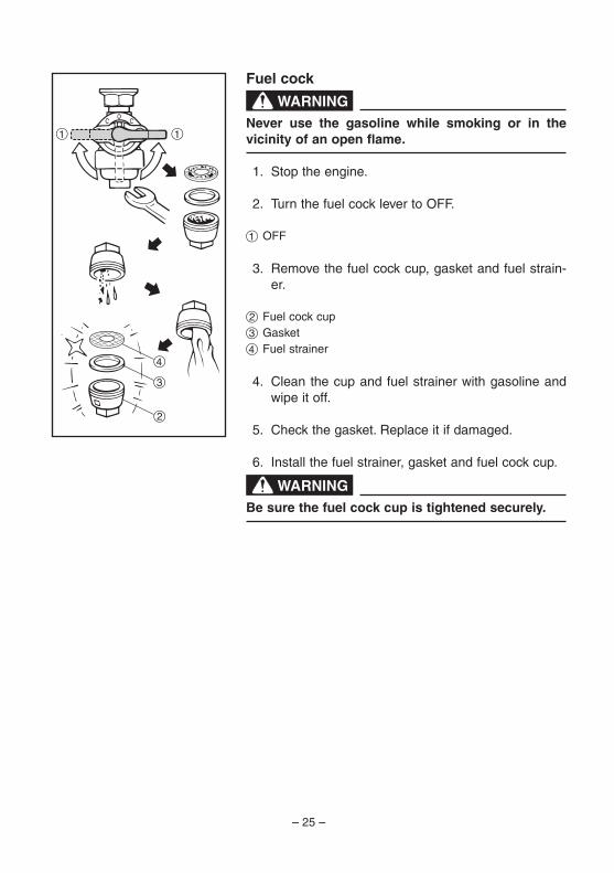
Fuel cock
WARNINGNever use the gasoline while smoking or in the vicinity of an open flame.
1. Stop the engine.
2. Turn the fuel cock lever to OFF.
1 OFF
3. Remove the fuel cock cup, gasket and fuel strain-er.
2 Fuel cock cup3 Gasket4 Fuel strainer
4. Clean the cup and fuel strainer with gasoline and wipe it off.
5. Check the gasket. Replace it if damaged.
6. Install the fuel strainer, gasket and fuel cock cup.
WARNINGBe sure the fuel cock cup is tightened securely.
4
11
3
2
7VB-F-10_E0.indd 25 2012/08/10 14:05:03

– 26 –
2
1
Fuel tank filter
WARNINGNever use the gasoline while smoking or in the vicinity of an open flame.
1. Remove the fuel tank cap and fuel tank filter.
1 Fuel tank cap2 Fuel tank filter
2. Clean the fuel tank filter with gasoline. Replace it if damaged.
3. Wipe the fuel tank filter and insert it.
4. Install the fuel tank cap.
WARNINGBe sure the fuel tank cap is tightened securely.
7VB-F-10_E0.indd 26 2012/08/10 14:05:03

– 27 –
2
1
STORAGELong term storage of your machine will require some preventive procedures to guard against deterioration.
Drain the fuel 1. Turn the engine switch to “OFF”.
1 “OFF”
2. Remove the fuel tank cap and fuel tank filter. Extract the fuel from the fuel tank into an approved gasoline container using a commercially available hand siphon. Then, install the fuel tank filter and fuel tank cap.
WARNINGFuel is highly flammable and poisonous. Check “SAFETY INFORMATION” (See page 1) carefully.
NOTICE
Immediately wipe off spilled fuel with a clean, dry, soft cloth, since fuel may deteriorate painted sur-faces or plastic parts.
3. Turn the engine switch to “ON”.
2 “ON”
4. Turn the fuel cock lever to ON.
3 ON
3
7VB-F-10_E0.indd 27 2012/08/10 14:05:04

– 28 –
4
5. Start the engine and leave it run until it stops. The engine stops in approx. 20 mins. time by run-
ning out of fuel.TIPDuration of the running engine depends on the amount of the fuel left in the tank.
6. Drain the fuel from the carburetor by loosening the drain screw on the carburetor float chamber.
4 Drain Screw
7. Turn the engine switch to “OFF”.
8. Turn the fuel cock lever to OFF.
9. Tighten the drain screw.
10. Tighten further if any screws, bolts and nuts are loose.
11. Store the multi-purpose engine in a dry, well-ven-tilated place, with the cover placed over it.
7VB-F-10_E0.indd 28 2012/08/10 14:05:04

– 29 –
EnginePerform the following steps to protect the cylinder, pis-ton ring, etc. from corrosion. 1. Remove the spark plug, pour about one table-
spoon of SAE 10W-30 or 20W-40 motor oil into the spark plug hole and reinstall the spark plug. Recoil start the engine by turning over several times (with ignition off) to coat the cylinder walls with oil.
2. Pull the recoil starter until you feel compression. Then stop pulling. (This prevents the cylinder and valves from rusting).
3. Clean exterior of the multi-purpose engine and apply a rust inhibitor.
4. Store the multi-purpose engine in a dry, well-ven-tilated place, with the cover placed over it.
5. The multi-purpose engine must remain in a verti-cal position when stored, carried or operated.
7VB-F-10_E0.indd 29 2012/08/10 14:05:04

– 30 –
1
700-006
TROUBLESHOOTING
Engine won’t start 1. Fuel systems No fuel supplied to combustion chamber. 2 No fuel in tank .... Supply fuel.
2. Engine oil system Insufficient 2 Oil level is low .... Add engine oil.
3. Electrical systems 2 Engine switch to “ON” and pull the recoil starter.
2 “ON”
2
Poor spark 2 Spark plug dirty with carbon or wet .... Remove
carbon or wipe spark plug dry. 2 Faulty ignition system .... Consult a Yamaha deal-
er.
2 Fuel in tank .... Fuel cock lever to ON.
1 ON
2 Clogged fuel line .... Clean fuel line. 2 Foreign matter in fuel cock .... Clean fuel cock. 2 Clogged carburetor .... Clean carburetor.
7VB-F-10_E0.indd 30 2012/08/10 14:05:04

– 31 –
A ENGINE DOES NOT START
B Turn the engine switch to “ON”, then pull the recoil starter and check if the oil warning light flickers.
C Does not flicker D Flickers
E Check engine oil level.
F OK G Level lowConsult aYamaha dealer.
Add engine oil.
K Check the spark plug.
9 Type: BPR4ES9 Gap: 0.7–0.8 mm (0.028–0.031 in)
L Incorrect M OKReplace or adjust gap.
Clean the spark plug.
N Check the following. 9 Fuel line clogging 9 Air f i l ter element
clogging.
O Clogged
P OK
QClean
or replace.
R OK
S Engine does not start.
H Pull the recoil starter and check the spark plug for spark strength.(See “WARNING”)
w 9 To prevent FIRE HAZARDS be
sure fuel is not present in the spark plug area.
9 To prevent FIRE HAZARDS be sure to place the spark plug as far away as possible from the spark plug hole and carburetor area.
9 To prevent ELECTRIC SHOCK do not hold spark plug lead with hand while testing.
I OK J Does not spark
T Consult a Yamaha dealer.
7VB-F-10_E0.indd 31 2012/08/10 14:05:05

– 32 –
SPECIFICATIONSDimensions
Unit MZ300A MZ300KOverall length mm (in) 387 (15.24) 404 (15.91)Overall width mm (in) 426 (16.77) 416 (16.38)Overall height mm (in) 464 (18.27) 294.5 (11.59)Dry weight kg (lb) 26 (57) 21 (46)
EngineUnit MZ300A MZ300K
Type Air cooled 4-stroke gasoline OHV
Air cooled 4-stroke gasoline OHV
Cylinder arrangement Inclined, 1 cylinder Inclined, 1 cylinderDisplacement cm3 296 296Bore × stroke mm (in) 80.0 × 59.0 (3.15 × 2.32) 80.0 × 59.0 (3.15 × 2.32)Fuel Unleaded gasoline Unleaded gasolineFuel tank capacity L (US gal, Imp gal) 5.5 (1.45, 1.2) —Engine oil quantity L (US qt, Imp qt) 1.0 (1.06, 0.88) 1.0 (1.06, 0.88)Ignition system TCI TCISpark plug: Type BPR4ES (NGK) BPR4ES (NGK) Gap mm (in) 0.7–0.8 (0.028–0.031) 0.7–0.8 (0.028–0.031)Net output* kW (PS) / r/min 7.0 (9.5) / 3600 7.0 (9.5) / 3600
* : The power rating of the engine indicated in the SPECIFICATIONS is the net power output tested on an engine model and measured at 3600 r/min.
Actual power output for an installed engine will vary depending on numerous factors, including the operating speed of the engine, environmental conditions, and other variables.
7VB-F-10_E0.indd 32 2012/08/10 14:05:05

– 33 –
Identification number recordsRecord your Primary I.D., and serial num-bers in the spaces provided, to assist you in ordering spare parts from a Yamaha dealer.Also record and keep these I.D. numbers in a separate place in case your machine is stolen.
PRI-I.D. NUMBER:
PRI-I.D.CODE SERIAL No.
MODEL
CONSUMER INFORMATION
Machine identificationThe machine serial number is stamped in the location as shown.
TIPThe first three digits of these numbers are for model identification; the remaining dig-its are the unit production number. Keep a record of these numbers for reference when ordering parts from a Yamaha dealer.
7VB-F-10_E0.indd 33 2012/08/10 14:05:05

– 34 –
EXHAUST EMISSION CONTROL SYSTEM AND COMPONENTS
Item Acronym 9 CARB.ASSY.,LH.&JT.,.......................CARB(Carburetor) CARBURETOR2 9 T.C.I.MAGNETOASSY.&.....................EI(ElectronicIgnition) PLUG,SPARK 9 CRANKCASE1&HEAD,.......................PCV(PositiveCrankcase CYLINDER1 Ventilation) 9 AIRFILTERASSY..................................ACL(AirCleaner) 9 MUFF.,2,CAP,NET,WIRE2& ARRESTER,SPARK
The above items and the corresponding acronyms are provided in accordance with U.S. EPA REGULATIONS FOR NEW NONROAD SPARK-IGNITION NONHANDHELD ENGINES and the CALIFORNIA REGULATIONS FOR 1995 AND LATER SMALL OFF-ROAD ENGINES.The acronyms conform to the latest version of the SAE’s recommended practice docu-ment J1930, “Diagnostic Acronyms, Terms, and Definitions For Electrical/Electronic System”.
It is recommended that these items be serviced by a Yamaha dealer.
7VB-F-10_E0.indd 34 2012/08/10 14:05:05

– 35 –
YamahaMotorCorporationUSA,SparkIgnitedSmallOff-RoadEquipment(SORE)
LimitedandEPAEmissionsWarranty
Yamaha Motor Corporation, USA, hereby warrants that new Yamaha Spark Ignited Small Off Road Engines, hereafter called SORE engines, purchased from an authorized Yamaha SORE engine dealer in the continental United States and Canada will be free from defects in material and workmanship for the period of time stated herein, subject to certain stated limitations.
PeriodofWarranty — Any new Yamaha SORE engine purchased for consumer, commercial, and/or rental use from an authorized Yamaha SORE engine dealer in the continental United States and Canada will be warrantied against defects in material or workmanship for a period of three (3) years from date of purchase, subject to exclusions noted herein.
Duringtheperiodofwarranty any authorized Yamaha SORE engine repair station will, free of charge, repair or replace, at Yamaha’s option, any part adjudged defective by Yamaha due to faulty workmanship or material from the factory. Parts used in warranty repairs will be warrantied for the balance of the product’s warranty period. All parts replaced under warranty become property of Yamaha Motor Corporation USA.
Emissionswarranty — emissions-related components will be warrantied for 3 years regardless of commercial or non-commercial use.
GeneralExclusions from this warranty shall include any failures caused by:a. Installation of parts or accessories that are not qualitatively equivalent to genuine
Yamaha parts.b. Abnormal strain, neglect, or abuse.c. Lack of proper maintenance.d. Accident or collision damage.
SpecificExclusions from this warranty shall include parts replaced due to normal wear or routine maintenance.
TheCustomer’sResponsibility under this warranty shall be to:1. Operate and maintain the SORE engine as specified in the appropriate Owner’s
Manual.2. Give notice to an authorized Yamaha SORE engine repair station of any and all
apparent defects within ten (10) days after discovery, and make the unit available at time for inspection and repairs as requested by the Yamaha SORE repair station.
7VB-F-10_E0.indd 35 2012/08/10 14:05:05

– 36 –
An approved Yamaha SORE engine repair station may be found by phoning 1-866-788-7398 (USA citizen) 1-866-788-7397 (Canadian citizen)
WarrantyTransfer: To transfer the warranty from the original purchaser to any subsequent purchaser(s), please contact 1-866-788-7398 (USA citizen) 1-866-788-7397 (Canadian citizen) to find out the necessary procedures. In no case will the warranty be extended beyond the original period.
YamahaMotorCorporation,USAmakesnootherwarrantyofanykind,expressedor implied.All impliedwarrantiesofmerchantabilityandfitnessforaparticularpurposewhichexceedtheobligationandtimelimitsstatedinthiswarrantyareherebydisclaimedbyYamahaMotorCorporation,USA,andexcludedfromthiswarranty.
Somestatesdonotallowlimitationsonhowlonganimpliedwarrantylasts,sotheabovelimitationmaynotapplytoyou.Alsoexcludedfromthiswarrantyareanyincidentalorconsequentialdamagesincludinglossofuse.Somestatesdonotallowtheexclusionorlimitationof incidentalorconsequentialdamages,sotheaboveexclusionmaynotapplytoyou.
Thiswarrantygivesyouspecificlegalrights,andyoumayalsohaveotherrightswhichvaryfromstatetostate.
Yamaha Motor Corporation, USA1-866-788-7398 (USA citizen)
1-866-788-7397 (Canadian citizen)
7VB-F-10_E0.indd 36 2012/08/10 14:05:05

– 37 –
YAMAHAOUTDOORPOWEREQUIPMENTCALIFORNIAEVAPORATIVEEMISSIONCONTROLWARRANTY
STATEMENTYOURWARRANTYRIGHTSANDOBLLIGATIONS
The California Air Resources Board and Yamaha Motor Corporation, USA are pleased to explain the evaporative emission control system’s warranty on your 2006 or later outdoor power equipment. In California, new equipment that use small off-road engines must be designed, built and equipped to meet the State’s stringent anti-smog standards. Yamaha Motor Corporation, USA must warranty the evaporative emission control system on your outdoor power equipment for the period listed below provided there has been no abuse, neglect or improper maintenance of your equipment.
Your evaporative emission control system may include parts such as: carburetors, fuel tanks, fuel lines, fuel caps, valves, canisters, filters, vapor hoses, clamps, connectors and other associated components. For engines less than or equal to 80cc, only the fuel tank is subject to the evaporative emission control warranty requirements of this section.
MANUFACTURER’SWARRANTYCOVERAGE:This evaporative emission control system is warranted for two years. If any evaporative emission-related part on your equipment is defective, the part will be repaired or replaced by Yamaha.
OWNER’SWARRANTYRESPONSIBILLITIES:As the outdoor power equipment owner, you are responsible for the performance of the required maintenance listed in your owner’s manual. Yamaha recommends that you retain all receipts covering the maintenance of your outdoor power equipment but Yamaha cannot deny warranty solely for the lack of receipts.
As the outdoor power equipment owner, you should however be aware that Yamaha may deny you warranty coverage if your outdoor power equipment or the part has failed due to abuse, neglect, improper maintenance or unapproved modifications.
You are responsible for presenting your outdoor power equipment to a Yamaha service center as soon as the problem exists. The warranty repairs should be completed in a reasonable amount of time, not to exceed 30 days.
If you have any questions regarding your warranty coverage or location of a warranty repair station, please call1-866-788-7398 (US) and 1-866-788-7397 (Canada).
7VB-F-10_E0.indd 37 2012/08/10 14:05:05

– 38 –
YAMAHAMOTORCORPORATION,U.S.A.SMALLOFFROADENGINES
CALIFORNIAEMISSIONCONTROLWARRANTY
YOURWARRANTYRIGHTSANDOBLIGATIONS
The California Air Resources Board and Yamaha Motor Corporation, U.S.A. are pleased to explain the emission control system warranty on your 2008 and later Small Off Road Engine (SORE). In California, new SORE engines must be designed, built and equipped to meet the State’s stringent anti-smog standards. Yamaha must warrant the emission control system on your SORE engine for the periods of time listed below provided there has been no abuse, neglect or improper maintenance of your SORE engine.
Your emission control system may include parts such as the carburetor or fuel-injection system, the ignition system, and catalytic converter. Also included may be hoses, belts, connectors and other emission-related assemblies.
Where a warrantable condition exists, Yamaha will repair your SORE engine at no cost to you including diagnosis, parts and labor.
MANUFACTURER’SWARRANTYCOVERAGE
The 2008 and later SORE engines are warranted for two years. If any emissions-related part on your engine is defective, the part will be repaired or replaced by Yamaha.
OWNER’SWARRANTYRESPONSIBILITIES
• As the SORE engine owner, you are responsible for the performance of the required maintenance listed in your owner’s manual. Yamaha recommends that you retain all receipts covering maintenance on your SORE engine, but Yamaha cannot deny warranty solely for the lack of receipts or for your failure to ensure the performance of all scheduled maintenance.
• As the SORE engine owner, you should however be aware that Yamaha may deny you warranty coverage if your SORE engine or a part has failed due to abuse, neglect, improper maintenance or unapproved modifications.
• You are responsible for presenting your SORE engine to a Yamaha dealer as soon as a problem exists. The warranty repairs should be completed in a reasonable time, not to exceed 30 days.
If you have any questions regarding your warranty rights and responsibilities, or to find an approved warranty repair station, please call 1-866-788-7398 USA and 1-866-788-7397 Canada.
Yamaha Motor Corporation, U.S.A. warrants to the ultimate purchaser and each subsequent purchaser thereafter that each new SORE engine certified for sale and registered in California are:
7VB-F-10_E0.indd 38 2012/08/10 14:05:05

– 39 –
1. Designed, built, and equipped so as to conform, at the time of sale, with all applicable regulations adopted by the California Air Resources Board, and
2. All warranted parts are free from defects in material and workmanship for the warranty period of the SORE engine or the period prior to the first scheduled replacement point of the warranted part as required by the maintenance schedule, if applicable, whichever is less. A defect exists when a deficiency in material or workmanship is such that an emission-related warranted part does not function as designed.
The warranty period begins on the date that the SORE engine is delivered to an ultimate purchaser or on the date it is first placed in service.
The warranty on emissions-related parts will be interpreted as follows:(1) Any warranted part that is not scheduled for replacement as required maintenance
in the written instructions required by subsection (d) must be warranted for the warranty period defined in Subsection (b)(2). If any such part fails during the period of warranty coverage, it must be repaired or replaced by the manufacturer according to Subsection (4) below. Any such part repaired or replaced under the warranty must be warranted for the remaining warranty period.
(2) Any warranted part that is scheduled only for regular inspection in the written instructions required by subsection (d) must be warranted for the warranty period defined in Subsection (b)(2). A statement in such written instructions to the effect of “repair or replace as necessary” will not reduce the period of warranty coverage. Any such part repaired or replaced under warranty must be warranted for the remaining warranty period.
(3) Any warranted part that is scheduled for replacement as required maintenance in the written instructions required by subsection (d) must be warranted for the period of time prior to the first scheduled replacement point for that part. If the part fails prior to the first scheduled replacement, the part must be repaired or replaced by the engine manufacturer according to Subsection (4) below. Any such part repaired or replaced under warranty must be warranted for the remainder of the period prior to the first scheduled replacement point for the part.
(4) Repair or replacement of any warranted part under the warranty must be performed at no charge to the owner at a warranty station.
(5) Notwithstanding the provisions of Subsection (4) above, warranty services or repairs must be provided at all manufacturer distribution centers that are franchised to service the subject engines.
(6) The owner must not be charged for diagnostic labor that leads to the determination that a warranted part is in fact defective, provided that such diagnostic work is performed at a warranty station.
(7) The manufacturer is liable for damages to other engine components proximately caused by a failure under warranty of any warranted part.
7VB-F-10_E0.indd 39 2012/08/10 14:05:05

– 40 –
(8) Throughout the emissions warranty period defined in Subsection (b)(2), the manufacturer must maintain a supply of warranted parts sufficient to meet the expected demand for such parts.
(9) Any replacement part may be used in the performance of any warranty maintenance or repairs and must be provided without charge to the owner. Such use will not reduce the warranty obligations of the manufacturer.
(10) Add on or modified parts that are not exempted by the Air Resources Board may not be used. The use of any non exempted add on or modified parts will be grounds for disallowing a warranty claim. The manufacturer will not be liable to warrant failures of warranted parts caused by the use of a non exempted add on or modified part.
(11) The manufacturer issuing the warranty shall provide any documents that describe that manufacturer’s warranty procedures or policies within five working days of request by the Air Resources Board.
WARRANTEDPARTSINCLUDEthe following:
1. Fuel Metering System Carburetor and internal parts (or fuel injection system) Air/fuel ratio feedback and control system Cold start enrichment system
2. Air Induction system Controlled hot air intake system Intake manifold Air filter
3. Ignition System Spark plugs* Magneto or electronic ignition system Spark advance/retard system
4. Exhaust Gas Recirculation (EGR) System EGR valve body, and carburetor spacer if applicable EGR rate feedback and control system
5. Air Injection System Air pump or pulse valve Valves affecting distribution of flow Distribution manifold
6. Catalyst or Thermal Reactor System Catalytic converter Thermal reactor Exhaust manifold
7VB-F-10_E0.indd 40 2012/08/10 14:05:05

– 41 –
7. Particulate Controls Traps, filters, precipitators, and any other device used to capture particulate emissions8. Miscellaneous Items Used in Above Systems Vacuum, temperature, and time sensitive Valves and switches Electronic controls Hoses, belts, connectors, and assemblies
9. Engine components damaged due to a failure under warranty or a warranted part
*The original spark plug(s) are warranted for the period of replacement indicated in the Owner’s Manual and not the useful life of the SORE engine (see your Owner’s Manual).
DURINGTHEPERIODOFTHISWARRANTY
Yamaha Motor Corporation, U.S.A. will repair or replace any warranted part deemed defective by Yamaha during the scope of the warranty without charge to the owner, including parts, labor, and diagnosis. This work must be done at an authorized Yamaha dealer. Give notice to an authorized Yamaha dealer of any apparent defects(s) within a reasonable period of time after discovery. The SORE engine must be made available for inspection by an authorized Yamaha dealer.
OWNER’SRESPONSIBILITY:
The owner of the SORE engine is responsible for the performance of required maintenance (see your Owner’s Manual). Receipts and maintenance records covering the performance of regular maintenance should be retained in the event questions arise concerning maintenance. The receipts should be transferred to each subsequent owner of this SORE engine.
The emission control systems of your Yamaha SORE engine were designed, built, tested, and certified as being in conformity with California emission control regulations using genuine Yamaha parts. Accordingly, it is recommended that any replacement part(s) used for maintenance, replacement, or repair of emission control systems be Yamaha parts. The owner may elect to have maintenance, replacement, or repair of the emission control devices and systems performed by any repair establishment or individual, and may elect to use parts other than Yamaha parts for such maintenance, replacement, or repair without invalidating this warranty. However, the cost of such service or parts will not be covered under the warranty.
7VB-F-10_E0.indd 41 2012/08/10 14:05:05

– 42 –
EXCLUSIONS: No warranty coverage will be allowed if the part(s) failure was caused by owner/operator abuse, neglect, tampering, improper adjustment unless performed by a dealer during warranty repair work, modification, misuse, alteration, or improper maintenance (see your Owner’s Manual).
Use of parts which are not qualitatively equivalent to genuine Yamaha parts, improper service, or lack of required maintenance which causes failure of a warranted part may constitute abuse and/or improper service, thereby invalidating warranty liability hereunder.This warranty does not cover damage resulting from accidents, acts of nature, or other events or occurrences beyond the control of Yamaha. Yamaha Motor Corporation, U.S.A. expressly disclaims responsibility for any and all consequential damages, such as loss of time, inconvenience, loss or use of the SORE engine, or commercial loss.
YAMAHA MOTOR CORPORATION, U.S.A1-866-788-7398 USA
1-866-788-7397 Canada
7VB-F-10_E0.indd 42 2012/08/10 14:05:05

7VB-F-10_E0.indd 43 2012/08/10 14:05:05

Read this manual carefully before operating this machine. This manual should stay with this machine if it is sold.
7VB-F-10_hyoshi.indd 3-4 2012/08/10 14:05:45

Multi-Purpose Engine
LIT-19626-01-807VB-F8199-10
PRINTED IN CHINA2012.08×1 !
(E)
MZ300
OWNER’S MANUAL
Read this manual carefully before operating this machine.
7VB-F-10_hyoshi.indd 1-2 2012/08/10 14:05:45