fuel system - atkusaatkusa.com › wp-content › uploads › ...sec-4-fuel-system.pdf · 4-1 fuel...
TRANSCRIPT
FUEL SYSTEM
FUEL TANK / FUEL COCK 4- 1
FUEL PUMP 4- 2
CARBURETOR 4- 3
CONTENTS
4
Gasoline must be handed carefully in an area well ventilated and away from fire or sparks.
CAUTION
4-1 FUEL SYSTEM
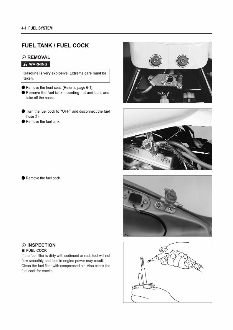
FUEL TANK / FUEL COCK
◉ REMOVAL
◉ INSPECTION� FUEL COCKIf the fuel filter is dirty with sediment or rust, fuel will not flow smoothly and loss in engine power may result. Clean the fuel filter with compressed air. Also check the fuel cock for cracks.
Gasoline is very explosive. Extreme care must be taken.
WARNING
● Remove the front seat. (Refer to page 6-1) ● Remove the fuel tank mounting nut and bolt, and
take off the hooks.
● Turn the fuel cock to “OFF”and disconnect the fuel hose ①.
● Remove the fuel tank.
● Remove the fuel cock.
①
FUEL SYSTEM 4-2
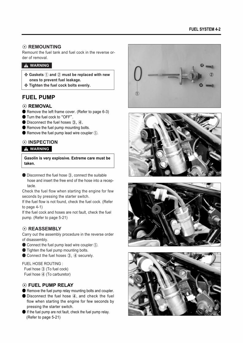
FUEL PUMP
◉ REMOVAL● Remove the left frame cover. (Refer to page 6-3)● Turn the fuel cock to “OFF”.● Disconnect the fuel hoses ③, ④.
● Remove the fuel pump mounting bolts.● Remove the fuel pump lead wire coupler ⑤.
● Disconnect the fuel hose ③, connect the suitable hose and insert the free end of the hose into a recep-tacle.
Check the fuel flow when starting the engine for few seconds by pressing the starter switch.If the fuel flow is not found, check the fuel cock. (Refer to page 4-1)If the fuel cock and hoses are not fault, check the fuel pump. (Refer to page 5-21)
◉ REMOUNTINGRemount the fuel tank and fuel cock in the reverse or-der of removal.
◉ INSPECTION
◉ REASSEMBLYCarry out the assembly procedure in the reverse order of disassembly.● Connect the fuel pump lead wire coupler ⑤.● Tighten the fuel pump mounting bolts.● Connect the fuel hoses ③, ④ securely.
FUEL HOSE ROUTING :Fuel hose ③ (To fuel cock)Fuel hose ④ (To carburetor)
� Gaskets ① and ② must be replaced with new ones to prevent fuel leakage.
� Tighten the fuel cock bolts evenly.
WARNING
Gasolin is very explosive. Extreme care must be taken.
WARNING③
④
④
⑤
③
④
①
②
⑤
◉ FUEL PUMP RELAY● Remove the fuel pump relay mounting bolts and coupler.● Disconnect the fuel hose ④, and check the fuel
flow when starting the engine for few seconds bypressing the starter switch.
● If the fuel pump are not fault, check the fuel pump relay.(Refer to page 5-21)
4-3 FUEL SYSTEM
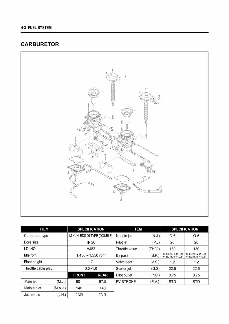
CARBURETOR
ITEM
Carburetor type
Bore size
I.D. NO.
Idle rpm
Float height
Throttle cable play
Main jet (M.J.)
Main air jet (M.A.J.)
Jet needle (J.N.)
SPECIFICATION
MIKUNI BDS 26 TYPE (DOUBLE)
ф 26
HJ82
1,450�1,550 rpm
17
0.5~1.0
90 87.5
140 140
2ND 2ND
ITEM
Needle jet (N.J.)
Pilot jet (P.J)
Throttle value (TH.V.)
By pass (B.P.)
Valve seat (V.S.)
Starter jet (G.S)
Pilot outlet (P.O.)
PV STROKE (P.V.)
SPECIFICATION
O-6 O-6
20 20
130 130
1.2 1.2
22.5 22.5
0.75 0.75
STD STD
FRONT REAR
# 1:0.9, # 2:0.9, # 1:0.9, # 2:0.9,# 3:0.8, # 4:0.8 # 3:0.8, # 4:0.8
FUEL SYSTEM 4-4
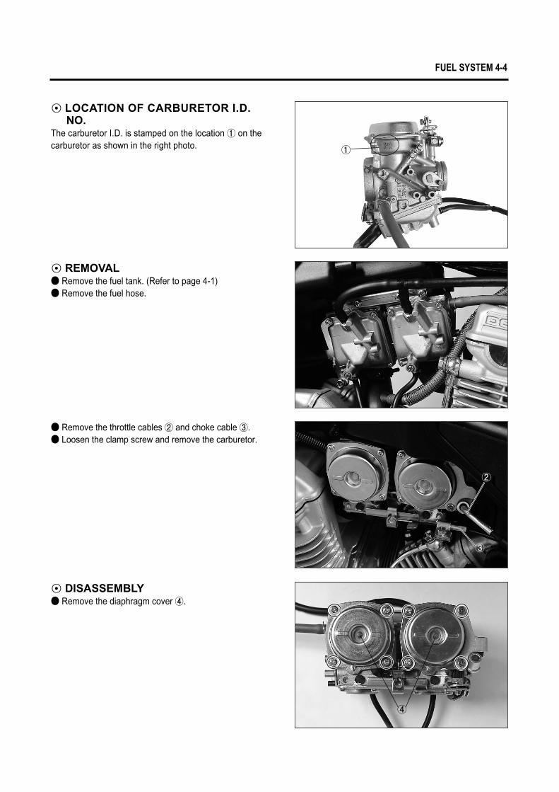
◉ LOCATION OF CARBURETOR I.D. NO.
The carburetor I.D. is stamped on the location ① on the carburetor as shown in the right photo.
◉ REMOVAL● Remove the fuel tank. (Refer to page 4-1)● Remove the fuel hose.
◉ DISASSEMBLY● Remove the diaphragm cover ④.
● Remove the throttle cables ② and choke cable ③.● Loosen the clamp screw and remove the carburetor.
①
②
③
④
4-5 FUEL SYSTEM
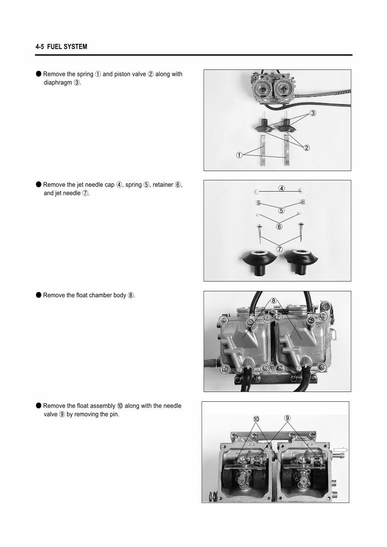
● Remove the spring ① and piston valve ② along with diaphragm ③.
● Remove the jet needle cap ④, spring ⑤, retainer ⑥, and jet needle ⑦.
● Remove the float chamber body ⑧.
● Remove the float assembly ⑩ along with the needle valve ⑨ by removing the pin.
①②
③
④
⑤
⑥
⑦
⑧
⑨⑩
FUEL SYSTEM 4-6
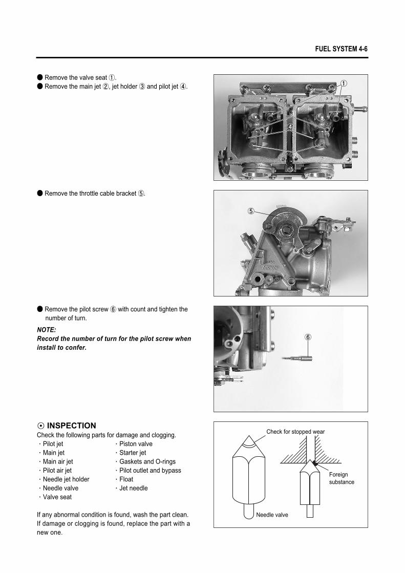
● Remove the valve seat ①.● Remove the main jet ②, jet holder ③ and pilot jet ④.
● Remove the throttle cable bracket ⑤.
● Remove the pilot screw ⑥ with count and tighten thenumber of turn.
NOTE:Record the number of turn for the pilot screw wheninstall to confer.
◉ INSPECTIONCheck the following parts for damage and clogging.∙Pilot jet ∙Piston valve∙Main jet ∙Starter jet∙Main air jet ∙Gaskets and O-rings∙Pilot air jet ∙Pilot outlet and bypass∙Needle jet holder ∙Float∙Needle valve ∙Jet needle∙Valve seat
If any abnormal condition is found, wash the part clean. If damage or clogging is found, replace the part with a new one.
①
⑤
③
②
④
⑥
Needle valve
Check for stopped wear
Foreign substance
4-7 FUEL SYSTEM
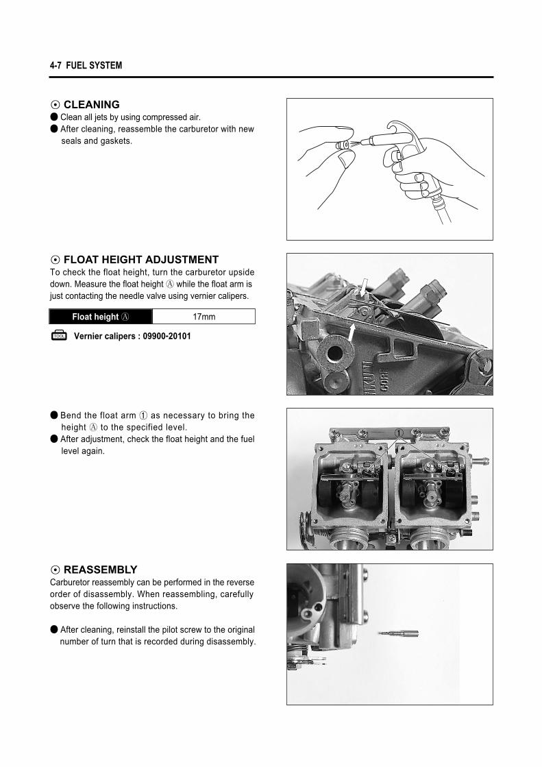
◉ CLEANING● Clean all jets by using compressed air.● After cleaning, reassemble the carburetor with new
seals and gaskets.
● Bend the float arm ① as necessary to bring the height � to the specified level.
● After adjustment, check the float height and the fuel level again.
◉ FLOAT HEIGHT ADJUSTMENTTo check the float height, turn the carburetor upside down. Measure the float height � while the float arm is just contacting the needle valve using vernier calipers.
◉ REASSEMBLYCarburetor reassembly can be performed in the reverse order of disassembly. When reassembling, carefully observe the following instructions.
● After cleaning, reinstall the pilot screw to the original number of turn that is recorded during disassembly.
Vernier calipers : 09900-20101
17mmFloat height ��
①
FUEL SYSTEM 4-8
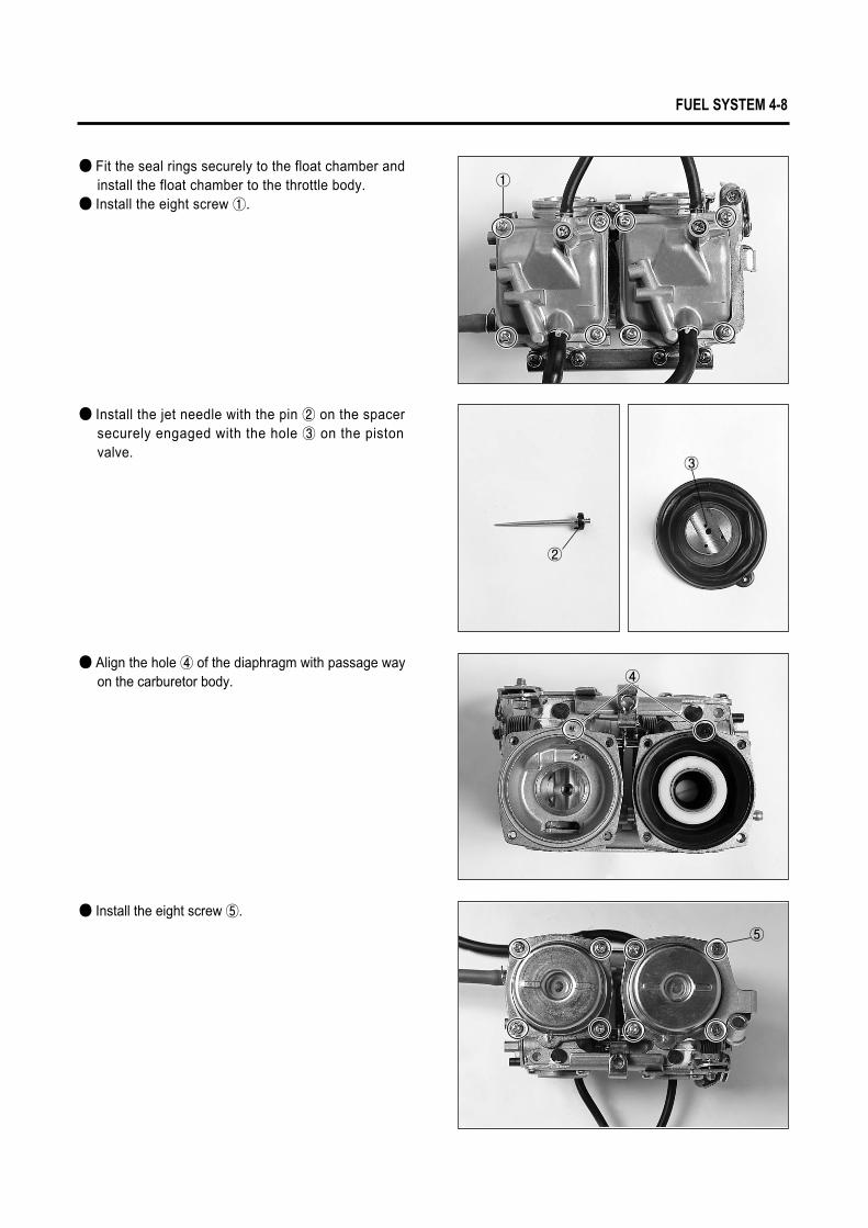
● Fit the seal rings securely to the float chamber and install the float chamber to the throttle body.
● Install the eight screw ①.
● Install the jet needle with the pin ② on the spacer securely engaged with the hole ③ on the piston valve.
● Align the hole ④ of the diaphragm with passage way on the carburetor body.
● Install the eight screw ⑤.
③
②
④
⑤
①
4-9 FUEL SYSTEM
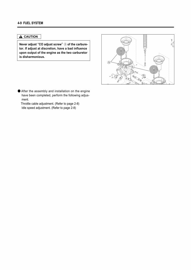
Never adjust “CO adjust screw”� of the carbure-tor. If adjust at discretion, have a bad influence upon output of the engine as the two carburetor is disharmonious.
CAUTION
● After the assembly and installation on the engine have been completed, perform the following adjus-ment.Throttle cable adjustment. (Refer to page 2-8)Idle speed adjustment. (Refer to page 2-8)
�