afh 10-222, volume 12 guide to bare base mechanical systems · fuel pump primer plug..... 30 ....
TRANSCRIPT

GUIDE TO BARE BASE
MECHANICAL SYSTEMS
AIR FORCE HANDBOOK 10-222, VOLUME 12
23 April 2009
DEPARTMENT OF THE AIR FORCE

BY ORDER OF THE AIR FORCE HANDBOOK 10-222, VOLUME 12
SECRETARY OF THE AIR FORCE 23 April 2009
Operations
GUIDE TO BARE BASE MECHANICAL SYSTEMS
ACCESSIBILITY: Publications and forms are available on the e-Publishing web site at www.epublishing.af.mil for downloading or ordering.
RELEASABILITY: There are no releasability restrictions.
OPR: HQ AFCESA/CEXX Certified by: HQ AF/A7CX Supersedes AFH 10-222V12, (Colonel Donald L. Gleason) 1 September 1999 Pages: 103
This handbook contains guidance on setting up and operating mechanical systems commonly encountered during bare base operations. It addresses, as appropriate, site selection and layout, major components, setup, operation, and shutdown of the M-80 Water Heater; Advanced Design Refrigerator, 300 Cubic Foot (ADR-300); Field Deployable Environmental Control Unit (FDECU); and the 130K Portable Heater. When coupled with information contained in the applicable technical orders and Air Force Pamphlet (AFPAM) 10-219, Vol 5, Bare Base Conceptual Planning Guide, and in-struction received at Silver Flag training sites, personnel should be capable of effectively setting up and operating the equipment under contingency condi-tions. This publication applies to all Air Force active duty, Air National Guard (ANG), and Air Force Reserve Command Civil Engineer units. It supports Air Force Instruction (AFI) 10-209, RED HORSE Program, and AFI 10-210, Prime Base Engineer Emergency Force (BEEF) Program. Refer recommended changes and questions about this publication to the Office of Primary Respon-sibility (OPR) using the AF IMT 847, Recommendation for Change of Publica-
tion; route AF IMTs 847 from the field through Major Command (MAJCOM) publications/forms managers. Ensure that all records created as a result of processes prescribed in this publication are maintained in accordance with Air Force Manual (AFMAN) 33-363, Management of Records, and disposed of in accordance with the Air Force Records Disposition Schedule (RDS) located at
Certified Current, 8 March 2012

AFH 10-222 Volume 12, 23April 2009
2
https://www.my.af.mil/gcss-af61a/afrims/afrims/HH. The use of the name or mark of any specific manufacturer, commercial product, commodity, or service in this publication does not imply endorsement by the Air Force.
SUMMARY OF CHANGES
This publication has been substantially revised and must be completely re-viewed. With the exception of the M-80 Water Heater, all other bare base mechanical systems previously addressed in this publication have been re-moved. Items added include the ADR-300 Refrigerator, Field Deployable Environmental Control Unit, and the 130K Portable Heater.
Chapter 1—INTRODUCTION .................................................................... 8 1.1. General Information .......................................................................... 8 1.2. Overview ........................................................................................... 8
Figure 1.1.Bare Base Mechanical Systems .................................................... 8 1.3. Safety ................................................................................................ 9 1.4. Additional Information.................................................................... 10
Chapter 2—M-80 WATER HEATER ....................................................... 11 2.1. General Information ........................................................................ 11
Figure 2.1. M-80 Heater ............................................................................... 11 2.2. Characteristics and Features ............................................................ 11
Table 2.1. M-80 Operating Fuel Types. ....................................................... 12 Figure 2.2. Select Fuel System Components ................................................ 12 Figure 2.3. Drum Fill Adapter and Flexible Hoses on Fuel Cans ................ 13 Figure 2.4. Sample Power Cable Assembly Connection .............................. 13 Figure 2.5. Burner Head Assembly .............................................................. 14 Figure 2.6. Sparkplug Electrodes ................................................................. 14 Figure 2.7. Ignition Cables, Transformer, Control Box, and Vessel ............ 15 Figure 2.8. Blower Assembly ....................................................................... 16 Figure 2.9. Sight Glass Assembly ................................................................ 16

AFH 10-222 Volume 12, 23 April 2009 3
Figure 2.10. Operating Control and Water Temperature Gauge .................. 17 Figure 2.11. Upper Manifold Assembly ....................................................... 18 Figure 2.12. Lower Manifold Assembly ...................................................... 18 Figure 2.13. Portable Water Pump with Hoses ............................................ 19
2.3. Set-Up Procedures ........................................................................... 19 Figure 2.14. Expedient Drum Float Water Intake ........................................ 21 Figure 2.15. Expedient Log Float Water Intake. .......................................... 21 Figure 2.16. M-80 Water Hose Connections ................................................ 22 Figure 2.17. Elbow and Smoke Stack with Guard Assembly....................... 23 Figure 2.18. Smoke Stack Bracket Screw .................................................... 23 Figure 2.19. Fuel Line Connections to Drum Fill Adapter .......................... 24 Figure 2.20. Electrical Connections ............................................................. 25 Figure 2.21. Pump Motor Rotation Direction .............................................. 26 Table 2.2. M-80 ―Before Operation‖ PMCS. ............................................... 27 Figure 2.22. Water Heater Power Switch ..................................................... 28 Figure 2.23. Manual Fuel Shut-Off Valve.................................................... 28 Figure 2.24. Reset Button on Flame Safeguard Control ............................... 29 Figure 2.25. Blower Air Shutter ................................................................... 29 Figure 2.26. Fuel Pump Primer Plug ............................................................ 30 Figure 2.27. Water Heater Drain Cock ......................................................... 31 Figure 2.28. Fuel Pump Motor Rotation Direction ...................................... 32
2.4. Operation ......................................................................................... 32 Table 2.3. M-80 ―During Operation‖ PMCS................................................ 34
2.5. Shutdown Procedures ...................................................................... 34 2.6. Preparation for Storage or Shipment ............................................... 35
Figure 2.29. Fuel Line Stowage Position ..................................................... 35
AFH 10-222 Volume 12, 23April 2009
4
Chapter 3—ADVANCED DESIGN REFRIGERATOR, 300 CUBIC
FOOT (ADR-300) .................................................................. 37 3.1. General Information ........................................................................ 37
Figure 3.1. ADR-300 .................................................................................... 37 3.2. Characteristics and Features ............................................................ 37
Figure 3.2. ADR-300 Features (Front View) ............................................... 38 Figure 3.3. Interior Floor Drain .................................................................... 39 Figure 3.4. Exterior Drain Plug .................................................................... 39 Figure 3.5. Tie-Down Rings ......................................................................... 40 Figure 3.6. Light Fixture and Switch ........................................................... 41 Figure 3.7. Plunger ....................................................................................... 41 Figure 3.8. Refrigeration Unit Features ........................................................ 42 Figure 3.9. Evaporator Unit Protrudes Inside Container .............................. 43 Figure 3.10. Controller Display and Keypad................................................ 43 Table 3.1. Display and Keypad References.................................................. 44
3.3. Set-Up Procedures ........................................................................... 45 Figure 3.11. Built-In Forklift Pockets .......................................................... 45 Figure 3.12. Installation of Refrigeration Unit with a Forklift ..................... 46 Figure 3.13. Power Supply Cable Connection to Refrigeration Unit ........... 47 Figure 3.14. Container Power Supply Cord Connection .............................. 48
3.4. Operation ......................................................................................... 48 Table 3.2. ADR-300 ―Before Operation‖ PMCS ......................................... 49 Figure 3.15. Controller Removal .................................................................. 53 Figure 3.16. Opened Back Cover on Controller ........................................... 54 Figure 3.17. Dip Switch 3 in Down/OFF (Fahrenheit) Position ................... 54 Table 3.3. ADR-300 Operational PMCS ...................................................... 55 Table 3.4. ADR-300 Lubrication Requirements .......................................... 55

AFH 10-222 Volume 12, 23 April 2009 5
3.5. Shutdown Procedures ...................................................................... 57 3.6. Preparation for Storage or Shipment ............................................... 57
Chapter 4—FIELD DEPLOYABLE ENVIRONMENTAL CONTROL
UNIT (FDECU) ...................................................................... 61 4.1. General Information ........................................................................ 61
Figure 4.1. Field Deployable Environmental Control Unit (FDECU) ......... 61 4.2. Characteristics and Features ............................................................ 61
Figure 4.2. FDECU Major Components ...................................................... 62 Figure 4.3. Master Control Panel ................................................................. 63 Figure 4.4. Remote Control Panel and Cable Routed Inside Shelter ............ 63 Figure 4.5. Sight Glass (or Liquid Refrigerant Indicator) ............................ 64 Figure 4.6. Replaceable Air Filter Located Inside Return Air Flange .......... 65 Figure 4.7. Supplemental Electric Resistance Heaters ................................. 65
4.3. Set-Up Procedures ........................................................................... 66 Figure 4.8. Siting FDECU ............................................................................ 66 Figure 4.9. FDECU Sample Configuration .................................................. 67 Figure 4.10. Unpacked FDECU Components .............................................. 68 Figure 4.11. Hair Cotter Pin Installation ...................................................... 69 Figure 4.12. Return Air Flange Assembly Removal .................................... 69 Figure 4.13. Removal of Shipping Cover from Return Air Volute .............. 70 Figure 4.14. Loosen Supply Panel Screws ................................................... 71 Figure 4.15. Removal of Quick Release Pins on Heater Barrel ................... 71 Figure 4.16. Perforated Holes and Clamps on Return Air Flange ................ 73 Figure 4.17. FDECU Connected to 208 Volts AC Power Supply ................ 73
4.4. Operation ......................................................................................... 74 Table 4.1. FDECU ―Before Operation‖ PMCS ............................................ 74 Table 4.2. Weekly PMCS ............................................................................. 75

AFH 10-222 Volume 12, 23April 2009
6
Table 4.3. Monthly PMCS ........................................................................... 75 Figure 4.18. Control Selection Toggle Switch (FDECU-2 Panel) ............... 76 Table 4.4. FDECU ―During Operation‖ PMCS ........................................... 78
4.5. Shutdown Procedures ...................................................................... 79 4.6. Preparation for Storage or Shipment ............................................... 79
Chapter 5—130K MULTI-FUELED, PORTABLE HEATER ............... 82 5.1. General Information ........................................................................ 82
Figure 5.1. 130K Heater ............................................................................... 82 5.2. Characteristics and Features ............................................................ 82
Figure 5.2. External Features ....................................................................... 84 Figure 5.3. Internal Features ........................................................................ 85 Figure 5.4. External Thermostat and CO Monitor ....................................... 86 Figure 5.5. Heater Control Panel .................................................................. 87 Table 5.1. 130K Heater Control Panel Components and Function .............. 88 Table 5.2. Heater Control Panel Display Messages ..................................... 89
5.3. Set-Up Procedures ........................................................................... 90 Figure 5.6. 130K Heater Sited Near Tent ..................................................... 90 Figure 5.7. Exhaust Extension (Stack) Installation ...................................... 91 Table 5.3. 130K Heater Operating Fuel Types ............................................. 92 Figure 5.8. Fuel Three-Way Valve Positions ............................................... 92 Figure 5.9. Air Duct Connection .................................................................. 93 Figure 5.10. Fresh Air Adjustment ............................................................... 93
5.4. Operation ......................................................................................... 95 Table 5.4. Heat Control Switch Settings ...................................................... 96
5.5. Shutdown Procedures ...................................................................... 96 5.6. Preparation for Storage or Shipment ............................................... 96

AFH 10-222 Volume 12, 23 April 2009 7
Figure 5.11. Fuel Tank Drain ....................................................................... 97 Figure 5.12. Ducts Secured with Hook and Loop ........................................ 97 Figure 5.13. Adapter Cover Installation ....................................................... 98 Chapter 6—INFORMATION COLLECTION, RECORDS, AND
FORMS .................................................................................. 99 6.1. Information Collections .................................................................. 99 6.2. Records ........................................................................................... 99 6.3. Forms (Adopted and Prescribed)..................................................... 99
Attachment 1—GLOSSARY OF REFERENCES AND SUPPORTING
INFORMATION ........................................................... 100

AFH 10-222 Volume 12, 23April 2009
8
Chapter 1
INTRODUCTION
1.1. General Information. This handbook addresses procedures used to set up and operate the M-80 Water Heater; Advanced Design Refrigerator, 300 Cubic Foot (ADR-300); Field Deployable Environmental Control Unit (FDECU); and the 130K Multi-Fuel Portable Heater (Figure 1.1). It is meant to be used by civil engineer heating, ventilation, air conditioning, and refrige-ration (HVAC/R) personnel in performing their beddown and sustainment mission taskings under contingency conditions. Users of this handbook should have a basic knowledge of bare base assets and their functions—readers without this fundamental knowledge should review the references in Attachment 1 and contact their unit’s training manager for training options.
1.2. Overview. The information presented here is designed to augment, not replace, technical orders for bare base mechanical systems. It highlights gen-eral characteristics, setup, and basic operating procedures. Personnel should refer to applicable technical orders for more detailed information, including maintenance, troubleshooting, and repair of these systems.
Figure 1.1. Bare Base Mechanical Systems.

AFH 10-222 Volume 12, 23 April 2009 9
1.3. Safety. Complying with proper safety procedures is vital when setting up and operating bare base mechanical systems. The flammable fuels and lethal voltages used in the operation of many of these systems are significant ha-zards, and adherence to all technical order warnings is critical to avoid per-sonal injury or death. Furthermore, the dangers associated with maintaining systems that use lethal voltages make it imperative that the techniques and procedures outlined in AFI 32-1064, Electrical Safe Practices, be applied at all times. Below are some general warnings that pertain to many of the bare base mechanical systems currently in use:
WARNING
Lethal voltage is present when mechanical systems are connected to a power source. Disconnect from power source before inspecting or repairing any electrical component. Be careful not to touch electrical connec-tions. Electrical shock and/or death may result from failure to heed this warning.
WARNING
Do not wear metal frame glasses, rings, watches or other metal jewelry while working on electronic equipment.
WARNING
Dangerous and lethal voltage is used in the operation of many bare base mechanical systems. Make sure power supply circuit breakers are in the OFF position before connecting or disconnecting the power supply. Failure to comply may result in serious injury or death to personnel.

AFH 10-222 Volume 12, 23April 2009
10
1.4. Additional Information. The siting and installation of some bare base mechanical systems may be impacted by the facilities they support; i.e., shower/shave units, personnel tents, kitchens, or laundry facilities. Person-nel should review technical orders for these facilities when attaching or integrating bare base mechanical systems. In addition, contact the Air Force Civil Engineer Support Agency (AFCESA) Reach-Back Center if you are looking for information not found in this publication or the references in Attachment 1. Call the Reach-Back Center at 888-232-3721 (commercial), DSN 523-6995, or email at [email protected].
WARNING
Mechanical systems are heavy and require an appro-priate lifting device to move. Personal injury can re-sult if moved without the aid of a lifting device.
WARNING
Exposed fuel and fuel vapor can ignite or explode, resulting in possible serious injury or death. Observe proper safety precautions when servicing the fuel sys-tem
WARNING
Fuel used with these systems is highly flammable and may cause severe burns or death if handled improper-ly.

AFH 10-222 Volume 12, 23 April 2009 11
Chapter 2
M-80 WATER HEATER
2.1. General Information. The M-80 water heater (Figure 2.1) is the prima-ry method of providing hot water at a bare base. It is used to supply hot water to bare base facilities, such as kitchens, shower and shave units, and laundry and medical facilities. It fulfills a critical sanitation need in addition to im-proving morale at austere locations. Operators and maintainers should ob-serve all technical order warnings and cautions to ensure safe operation of the water heater and all associated equipment.
Figure 2.1. M-80 Water Heater.
2.2. Characteristics and Features. The water heater is a skid-mounted, self-contained, liquid fuel-fired boiler. It will operate on several types of fuel; including diesel, jet fuel, or fuel oil (Table 2.1). The heater also uses 208-volt, three-phase power (generator or commercial power) to operate its blower and fuel pump. The supporting water pump (not a component of the M-80) also uses this power source. The water heater delivers water at a rate of approximately 9 gallons per minute (gpm) at temperatures between 100o Fahrenheit (F) and 190o F. Water enters and exits the vessel through sepa-rate manifolds, and the water supply can be from natural sources such as

AFH 10-222 Volume 12, 23April 2009
12
lakes, rivers, or bare base and commercial water distribution systems. Safe-ty features include an automatic flame safeguard control system and an au-dio alarm that alerts the operator when a low fuel condition or loss of flame occurs. Although the M-80 itself is relatively small, it is very heavy and requires a forklift to position the unit. In its crated configuration, the heater weighs approximately 1,065 pounds. Even when unpacked, the heater still weighs approximately 465 pounds. Prominent features of the heater consist of the following systems, subassemblies, and supporting equipment items.
Table 2.1. M-80 Operating Fuel Types.
Fuel Types
Diesel VV-F-800, DF-A, DF-1, DF-2 Jet Fuel MIL-T-5624 JP-4, JP-5 Jet Fuel MIL-T-83133, JP-8 Fuel Oil Commercial Fuel No. 2
2.2.1. Fuel System. The fuel system includes components such as the fuel pump, filter, shutoff valve, gauges, and supply hoses (Figure 2.2). Fuel is commonly provided in 55-gallon drums (5-gallon jerry cans can be used) and fed to the heater through the drum fill adapter and flexible hose assembly (Figure 2.3). Excess fuel returns through a fuel return hose connected to the bottom of the fuel pump and the return fitting on the drum fill adapter.
Figure 2.2. Select Fuel System Components.

AFH 10-222 Volume 12, 23 April 2009 13
Figure 2.3. Drum Fill Adapter and Flexible Hoses on Fuel Cans.
2.2.2. Power System. Electrical power to the M-80 water heater is supplied from an external power source through a power cable assembly that extends from a power distribution panel or generator. The power cable assembly is part of the bare base kitchen, shower, laundry, and medical facilities and typi-cally consists of a dual-junction power cable that connects the power source to the water heater and supporting water pump (Figure 2.4).
Figure 2.4. Sample Power Cable Assembly Connection.

AFH 10-222 Volume 12, 23April 2009
14
2.2.3. Burner Head Assembly. The burner head assembly (Figure 2.5) at the center of the combustion chamber serves as a mounting platform for the fuel nozzle, two sparkplug electrodes, the burner assembly sight glass, and the ultraviolet (UV) or infrared (IR) scanner that is part of the flame safeguard control system. When the power switch is activated, the sparkplug electrodes (Figure 2.6) are energized to ignite the fuel mixture from the fuel nozzle to heat the water.
Figure 2.5. Burner Head Assembly.
Figure 2.6. Sparkplug Electrodes. (Exposed to show configuration only)

AFH 10-222 Volume 12, 23 April 2009 15
2.2.4. Ignition Transfer Assembly and Ignition Cables. The ignition trans-fer assembly is where the transformer is located, and the ignition cables lead from the transformer to the sparkplug electrodes (Figure 2.7). The transfor-mer provides the voltage needed to fire the electrodes.
2.2.5. Control Box Assembly. The control box (Figure 2.7) contains most of the electrical contacts, relays, switches, and controls for the heater, including the power switch and twist-lock receptacle, motor contactor reset, flame fail-ure alarm, and hour meter.
2.2.6. Water Vessel. The water vessel (Figure 2.7) contains the water being heated. It holds approximately 24 gallons.
Figure 2.7. Ignition Cables, Transformer, Control Box, and Vessel.
2.2.7. Blower Assembly. The blower assembly (Figure 2.8) provides and controls airflow to the burner. The amount of air is controlled by an adjusta-ble shutter assembly on the blower. The shutter assembly consists of an air band and air band adjustment rivet.

AFH 10-222 Volume 12, 23April 2009
16
Figure 2.8. Blower Assembly.
2.2.8. Sight Glass Assembly. Two sight glasses (Figure 2.9) are on the M-80 heater. One is for visually inspecting flame in the combustion chamber and the other is to check firing of the sparkplug electrodes.
Figure 2.9. Sight Glass Assembly.

AFH 10-222 Volume 12, 23 April 2009 17
2.2.9. Operating Control and Water Temperature Gauge (Figure 2.10). The operating control is used to set the desired water temperature. Although the control has a calibrated scale ranging from 0o F to 250o F, it actually regu-lates the burner to maintain the water temperature between 100o F and 190o F. The water temperature gauge indicates the temperature of the water inside the water heater.
Figure 2.10. Operating Control and Water Temperature Gauge.
2.2.10. Upper Manifold Assembly. The upper manifold (Figure 2.11) in-cludes the hot water output valve, valve vent, pressure relief valve, and high limit control. The hot water output valve controls the flow of hot water from the upper manifold and through the hot water supply hose. The vent valve is used to bleed air from the water heater. The pressure relief valve activates and relieves the pressure when the internal temperature exceeds the pre-scribed limit. Lastly, the high limit control deactivates the fuel solenoid valve when the water temperature exceeds 190o F.
2.2.11. Lower Manifold Assembly. The lower manifold (Figure 2.12) serves as the water intake point of the heater to which the water hose is con-nected.

AFH 10-222 Volume 12, 23April 2009
18
Figure 2.11. Upper Manifold Assembly.
Figure 2.12. Lower Manifold Assembly.

AFH 10-222 Volume 12, 23 April 2009 19
2.2.12. Water Pump. The portable water pump is supporting equipment and is not a component of the M-80 water heater. It is usually packaged with bare base shower, kitchen, laundry, and medical facilities. The pump is electrically driven and draws water from sources such as lakes and rivers, water bladders, and other base water distribution sources. A water hose with a 1-inch inside diameter attaches to the intake side of the pump and serves as the suction line from the water source. With surface water sources like lakes, streams, or riv-ers, the suction hose is equipped with a strainer assembly on the end to pre-vent entry of debris. The pump connects to the water heater using a 6-foot long, 1-1/2 inch inside diameter hose (Figure 2.13).
Figure 2.13. Portable Water Pump with Hoses.
2.3. Set-Up Procedures. The siting and installation of the water heater unit should be according to specifications of the supported facility; i.e., shower/shave unit, kitchen, or laundry. In many cases, siting and installa-tion will be further impacted by the type of water source used and the equipment available. For example, Basic Expeditionary Airfield Resources (BEAR) sets have different pumps and hoses that may require special siting and installation procedures. Regardless of the water source or equipment used, attempt to locate the water heater away from avenues of pedestrian traffic and far enough away from its supported facility to permit ready

AFH 10-222 Volume 12, 23April 2009
20
access for operation, maintenance, and refueling. Also, ensure drainage flows away from the heater once a final location is selected. The following paragraphs address other fundamental procedures for setting up the water heater and associated equipment.
2.3.1. Connect Water Pump to Water Source. Use the following proce-dures when connecting the pump to surface, open, and closed water sources. If surface water (lake, river, or stream) is used as the water source, general guidelines suggest the water pump should be located within 20 feet of the source and not more than 15 feet above it. However, a more likely scenario may have the water pump connected directly to a water bladder or tank placed near the heater unit.
2.3.1.1. Install the main water supply hose (25-foot suction hose) on the pump inlet connector.
2.3.1.2. If using surface or open water sources, install the strainer or intake screen on the opposite end of the suction hose. Then place the strainer end of the suction hose into the water source, ensuring the hose and strainer are posi-tioned so that sediment, sand, and other unwanted particles do not enter the suction hose. Make sure the strainer is completely submerged when in opera-tion. Figure 2.14 and Figure 2.15 provide two improvised methods of plac-ing the suction hose in open water sources. Almost any floatable object can be used in lieu of the 55-gallon drum and logs depicted in the two examples. See AFPAM 10-219, Volume 7, Expedient Methods, for more examples.
2.3.1.3. If using a closed water supply (bladder, tanks, facility water source, etc.), connect the pump suction hose without the strainer directly to the water source.
WARNING
Be sure that fuel lines do not touch or cross water hos-es, power cable, or exhaust duct. Melting/damage can occur, causing leaking fuel and water or electrical hazards. Death by electrocution, fire, or explosion could result.

AFH 10-222 Volume 12, 23 April 2009 21
Figure 2.14. Expedient Drum Float Water Intake.
Figure 2.15. Expedient Log Float Water Intake.

AFH 10-222 Volume 12, 23April 2009
22
2.3.2. Assemble and Connect Water Heater. Position the water heater on level ground and within five feet of the water pump. Prepare the heater unit for operation as follows:
2.3.2.1. Connect the water heater to the pump using the 6-foot hose section (Figure 2.16). The hose should extend from the pump to the heater intake manifold (lower manifold).
2.3.2.2. Connect the hot water supply hose (female end) to the hot water out-let fitting (upper manifold) on the heater (Figure 2.16). Then connect the other end of the hose to an appropriate mixing valve, if applicable. Although mixing valves have the same function, various types may be available in BEAR, so connection methods may differ.
Figure 2.16. M-80 Water Hose Connections.
CAUTION
To prevent equipment damage, ensure hose couplings are free of dirt or foreign matter and the quick discon-nect (QD) coupling gaskets are in place before con-necting hoses.

AFH 10-222 Volume 12, 23 April 2009 23
2.3.2.3. Install the exhaust stack elbow on the water heater with a slight turn to the right to seat the pin in the slot. Attach the smoke stack and guard as-sembly on the heater (Figure 2.17). Make sure the bracket screw (Figure
2.18) is tightened to secure the smoke stack and guard assembly.
Figure 2.17. Elbow and Smoke Stack with Guard Assembly.
Figure 2.18. Smoke Stack Bracket Screw.

AFH 10-222 Volume 12, 23April 2009
24
2.3.2.4. Place the fuel container about 5 feet from the heater. Screw the drum fill adapter into the top of the fuel container. Then devise a fuel spill containment system around the fuel storage container(s) and make sure a fire extinguisher is handy. Connect the fuel line from the fuel pump filter to the suction (supply) fitting on the drum fill adapter. Afterwards, connect the second fuel line from the fuel pump to the return fitting on the adapter (Figure 2.19).
Figure 2.19. Fuel Line Connections to Drum Fill Adapter.
CAUTION
Use only authorized fuels. Failure to do so may dam-age the equipment. See Table 2.1 for authorized fuel types.
WARNING
Fuel used with the water heater is highly flammable and may cause severe burns or death if handled im-properly.

AFH 10-222 Volume 12, 23 April 2009 25
2.3.2.5. Connect electrical cable assemblies to the water pump, heater, and power source (Figure 2.20). Ensure the source is 208-volt, 3-phase, 60-cycle.
Figure 2.20. Electrical Connections.
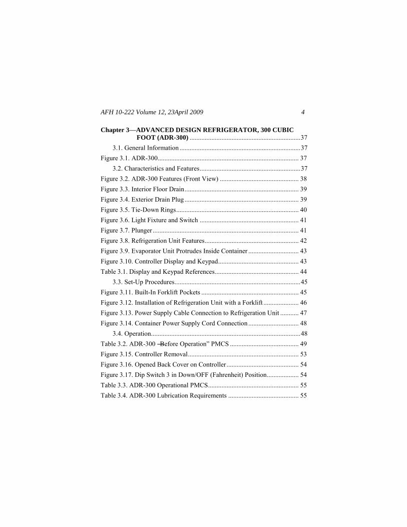
2.3.2.6. Verify the electrical cable junction box is properly wired for the wa-ter pump by quickly turning the water pump switch on and off while noting the rotation direction of the motor. The motor must turn in the same direction as the arrow on the pump housing (Figure 2.21). If the rotation is incorrect, have an electrician reverse the leads in the junction box (a three-phase motor must have the phases properly connected to operate and run in the proper direction).
WARNING
Lethal voltage is present when the water heater is connected to a power source. Ensure power source is not energized when connecting power cables. Ensure that the power distribution cable is not frayed or damaged and does not lay in standing water. Serious injuries or death to personnel by electrocution could result.
AFH 10-222 Volume 12, 23April 2009
26
Figure 2.21. Pump Motor Rotation Direction.
2.3.3. Perform Preoperational Checks. Several checks should be accom-plished before starting the water heater. Make final checks on the power cables and water pump, followed by preventive maintenance checks and ser-vices (PMCS) on the water heater.
2.3.3.1. Check the power cables to verify there are no cracks or other damage. Ensure power cables are properly connected to the water pump, water heater, and power source. Make sure the water pump intake hose strainer and water pump motor are clear of obstructions. If applicable, check the condition of mix-ing valves.
2.3.3.2. Perform ―Before Operation‖ PMCS on the water heater according to Table 2.2. Ensure these checks are completed before making initial heater adjustments.

AFH 10-222 Volume 12, 23 April 2009 27
Table 2.2. M-80 “Before Operation” PMCS.
Check: Unserviceable If:
Inspect the water heater for general signs of physical damage.
The water heater is damaged.
Check the fuel shutoff valve. De-termine that it moves freely and does not bind or catch. Check for bent valve stem.
The fuel shutoff valve is binding or catching and does not open and close freely. Valve stem is bent.
Check condition of ignition cables. Determine if the cables are loose or frayed.
Cables are frayed or loose.
Check the vent valve and deter-mine that it moves freely and does not bind or catch. Check for bent valve stem.
The vent valve is inoperative.
Check the combustion chamber sight glass. Determine if the glass is undamaged and assembly is se-curely installed.
The sight glass is missing or the assembly is not correctly installed, or is loose or damaged.
Check the serviceability of the smoke stack and guard assembly. Parts should fit tightly and have no dents. Check for excessive rust.
Parts are dented and do not fit to-gether well or there is excessive rust on the parts, preventing a proper fit.
AFH 10-222 Volume 12, 23April 2009
28
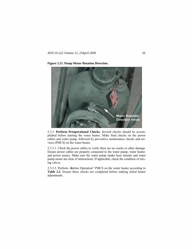
2.3.4. Make Initial Heater Adjustments. Make the following initial adjust-ments before starting water heater operation:
2.3.4.1. Make sure the water heater power switch (Figure 2.22) is turned OFF.
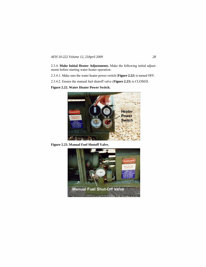
2.3.4.2. Ensure the manual fuel shutoff valve (Figure 2.23) is CLOSED.
Figure 2.22. Water Heater Power Switch.
Figure 2.23. Manual Fuel Shutoff Valve.

AFH 10-222 Volume 12, 23 April 2009 29
2.3.4.3. Press the reset button on the flame safeguard control (Figure 2.24) inside the control box assembly.
2.3.4.4. Open the blower air shutter approximately halfway (Figure 2.25).
Figure 2.24. Reset Button on Flame Safeguard Control.
Figure 2.25. Blower Air Shutter.

AFH 10-222 Volume 12, 23April 2009
30
2.3.4.5. Prime the fuel pump by opening the fuel pump primer plug and fill-ing the fuel pump with fuel (Figure 2.26). Then replace the plug.
Figure 2.26. Fuel Pump Primer Plug.
2.3.4.6. Ensure all water lines are connected and the water heater drain cock is closed (Figure 2.27).
2.3.4.7. Prime water pump according to directions or technical information for the specific pump being used.
2.3.4.8. Open the vent valve on the top of the water vessel and turn on the water pump. Allow vessel to fill with water until a steady stream of water comes out of the vent valve, then close the vent valve and turn off the pump. Note. Failure to bleed all air from the water heater will activate the low water switch, sounding the buzzer and preventing the unit from starting.
WARNING
Exposed fuel and fuel vapor can ignite or explode, resulting in possible serious injury or death. Observe proper safety precautions when servicing the fuel sys-tem.

AFH 10-222 Volume 12, 23 April 2009 31
Figure 2.27. Water Heater Drain Cock.
2.3.4.9. Set the operating control (temperature) knob to the desired setting. Temperature should be set between 160o F and 210o F.
2.3.4.10. Turn the heater power switch on and off quickly and note the rota-tion of the blower and fuel pump motor. If the motor is not rotating in the same direction as the arrow on top of the fuel pump (Figure 2.28), have an electrician reverse the leads on the control box power input plug (a three-phase motor must have the phases properly connected to operate and run in the proper direction).
WARNING
Lethal voltage is present when the water heater is connected to a power source. Disconnect from power source before inspecting or repairing any electrical component. Be careful not to touch electrical connec-tions. Electrical shock and/or death may result from failure to heed this warning.

AFH 10-222 Volume 12, 23April 2009
32
Figure 2.28. Fuel Pump Motor Rotation Direction.
2.4. Operation. Observe all safety precautions and follow the steps listed below to start up and operate the heater unit:
2.4.1. Ensure the power source and water supply are turned ON.
2.4.2. Ensure the water pump and fuel pump are primed and the water vessel is full.
2.4.3. Open the fuel shutoff valve. The fuel pressure gauge should read 100 pounds per square inch (PSI). If operating at high altitudes, it may be neces-sary to adjust the fuel pressure. Refer to the water heater technical order for more information.
WARNING
Fuel is very flammable and can ignite easily. To avoid serious injury or death, keep fuel away from open flames. Do not work on fuel system when heater is hot. Shut off heater and do not smoke when working on fuel system.

AFH 10-222 Volume 12, 23 April 2009 33
2.4.4. Turn the heater power switch ON. The combustion should occur within seven (7) seconds. The ignition spark can be viewed through the burner as-sembly sight glass, and the combustion can be viewed through the combus-tion chamber sight glass.
2.4.4.1. If combustion fails to occur, the water heater will automatically at-tempt another ignition. If combustion still does not occur, the buzzer alarm will sound and the ignition spark will shutdown.
2.4.4.2. When the buzzer sounds, press the reset button on the flame safe-guard control. If combustion still does not occur within two minutes, refer to the technical order for troubleshooting actions.
2.4.5. After start up, and if necessary, slowly open the air shutter on the blower assembly until exhaust gases are transparent and smokeless. It may also be necessary to readjust the air shutter because normal vibration of the heater during operation could cause the air shutter to shift over time.
2.4.6. Ensure the water pump is on and the water pump valve is open. Also, verify the hot water output valve on the top of the water vessel is closed.
2.4.7. When the preset hot water temperature is reached, open the hot water output valve to deliver hot water (output valve is in-line with the pipe when open).
2.4.8. Open the valve at a dispensing point (shower, sink, etc.) and adjust mixing valve temperature control to desired temperature.
2.4.9. During operation of the heater, several continual system checks should be made. See Table 2.3 for a list of system checks.
WARNING
Ensure water heater has cooled down before touching any part that may still be hot. Failure to comply may result in scalding or burning to skin.

AFH 10-222 Volume 12, 23April 2009
34
Table 2.3. M-80 “During Operation” PMCS.
Check: Unserviceable If:
Check fuel pressure gauge to veri-fy it reads 100 PSI. Check for bro-ken glass or stained dial.
The gauge is not in the proper range. Glass is broken and dial stained.
Check the fuel pump, fuel lines, fuel filter, and drum fill adapter for leaks, loose connections, and dam-age.
Fuel leaks, loose connections, or damage to fuel supply system is noted.
Check exhaust gases and, if neces-sary, adjust the air shutter until the exhaust emission is clear. Check the shutter for correct oper-ation. The pin and shutter should operate smoothly and not bind or stick.
The pin or shutter does not move freely or they cannot be adjusted.
2.5. Shutdown Procedures. Perform the following shutdown procedures after normal use:
2.5.1. Close the fuel shutoff valve and turn OFF the heater power switch and water pump.
2.5.2. If the heater will be subjected to freezing temperatures (below 32o F) or will not be used for five or more days, also complete the following:
2.5.2.1. Remove the fuel supply hose from the fuel drum fill adapter, and place the end of the hose into a suitable container to drain fuel from the hose.
2.5.2.2. Turn ON the heater power switch, and operate the unit until the con-tainer is almost empty. Ensure the fuel shutoff valve is closed, and let the heater operate until the combustion flame goes out. Afterward, turn the water heater switch OFF.

AFH 10-222 Volume 12, 23 April 2009 35
2.6. Preparation for Storage or Shipment. Perform the following proce-dures before storing or moving the water heater:
2.6.1. Cease water-heating operations using shutdown procedures described in paragraph 2.5.
2.6.2. Disconnect the power cable from the water heater and water pump.
2.6.3. Retrieve suction line from the water source and disconnect the strainer.
2.6.4. Disconnect water hoses from the lower and upper manifold assemblies and drain the hoses. The M-80 will drain when hoses are disconnected.
2.6.5. Verify the fuel shutoff valve is closed and disconnect fuel lines from the fuel drum fill adapter. Stow the fuel lines on the holder under the water vessel (Figure 2.29).
Figure 2.29. Fuel Line Stowage Position.
WARNING
Ensure power has been disconnected from the water heater control box assembly. Death or serious injury to personnel may result from electrocution. Ensure the water heater has cooled down before attempting to prepare it for movement. This will avoid possible injuries to personnel from burns and scalding.
AFH 10-222 Volume 12, 23April 2009
36
2.6.6. Disconnect and remove the smoke stack and drum fill adapter. Close the air shutter on the blower assembly.
2.6.7. Thoroughly clean and dry all items then pack them in their appropriate shipping boxes.
2.6.8. Perform ―after use‖ PMCS according to applicable technical data when time and circumstances permit.

AFH 10-222 Volume 12, 23 April 2009 37
Chapter 3
ADVANCED DESIGN REFRIGERATOR, 300 CUBIC FOOT
(ADR-300)
3.1. General Information. The ADR-300 (Figure 3.1) provides refrigerated storage for a wide range of items, including food, medical supplies, and ca-davers. The system also provides thermal protection for stored items during transport, including air shipment. It provides 281 cubic feet of storage space and can maintain inside temperatures as low as 0o F at 110o F ambient tem-perature. The system does not require personnel in any specific Air Force Specialty (AFS) for normal operation; however, AFS 3E1X1, Heating, Ventilation, Air Con-ditioning and Refrigeration (HVAC/R) technicians may be required for setup and some maintenance activities.
Figure 3.1. ADR-300.
3.2. Characteristics and Features. The ADR-300 is an insulated container constructed from aluminum-skinned composite panels and mounted on a formed aluminum skid. The refrigerator is available in green and desert sand colors. The skid includes forklift pockets and replaceable cargo rails on all sides. Some of the regular features are illustrated in Figure 3.2. The lever-activated container door lock is located on the left side of the door. The door

AFH 10-222 Volume 12, 23April 2009
38
is further secured with two rotating door handle unit assemblies. Sling rings are attached to the four top corners of the container and used to lift the system either by crane or helicopter sling. Additional features are addressed in the following paragraphs.
Figure 3.2. ADR-300 Features (Front View).
3.2.1. Floor Drain and Exterior Drain Plug. A floor drain (Figure 3.3) re-moves liquids trapped inside the container by discharging the fluids through a one-inch diameter tube to a port at the front of the skid. A plug at the exit end of the tube seals the drain (Figure 3.4). This plug also serves as a pressure re-lease in the event of a sudden decrease of outside pressure.

AFH 10-222 Volume 12, 23 April 2009 39
Figure 3.3. Interior Floor Drain.
Figure 3.4. Exterior Drain Plug.
3.2.2. Interior Shelving and Tie-Down Rings. The container has two sets of removable shelving, and each set consists of five shelves. Every shelf has a storage surface measuring 72 3/4 x 21 inches and can hold up to 300 pounds (lbs). The shelves are easily adjusted and can be disassembled and removed

AFH 10-222 Volume 12, 23April 2009
40
from the container to accommodate bulk materials or to ease cleaning of the interior. Bulk cargo not stored on shelves can be secured to the tie-down rings located on the container floor (Figure 3.5). Fourteen tie-down rings are lo-cated around the inside perimeter of the container. Each ring can withstand up to 7,500 lbs of tension.
Figure 3.5. Tie-Down Rings.
3.2.3. Interior Light. The inside of the refrigerator is lighted by a single light fixture located above the door (Figure 3.6). The light is controlled by a switch mounted next to the light fixture. The pilot light outside the door illu-minates when the inside light is switched on, alerting users that the light is on without opening the door. Power is supplied to the switch and light through a surface-mounted conduit that runs along the upper left inside of the container.
3.2.4. Quick-Release Plunger. The quick-release plunger (Figure 3.7) is located on the interior side of the refrigerator door and is used in conjunction with the interior door handle unit assemblies to open the door from the inside.

AFH 10-222 Volume 12, 23 April 2009 41
Figure 3.6. Light Fixture and Switch.
Figure 3.7. Plunger.
3.2.5. Refrigeration Unit. The refrigeration unit (Figure 3.8) maintains the temperature inside the container and includes the refrigerator assembly, pow-er supply, and control components. The unit mounts in an opening on the back of the container and is very heavy. Handle this unit carefully, and al-ways comply with technical order safety procedures.

AFH 10-222 Volume 12, 23April 2009
42
3.2.5.1. Power Supply. A 208/230-volt, 3-phase, 50-60 hertz (Hz) power supply is needed to operate the refrigeration unit. Power is supplied to the refri-gerator and various control components through a connector on the mounting plate just below the condenser section (Figure 3.8). A power cable also extends from the refrigeration unit to supply power to the inside light fixture.
Figure 3.8. Refrigeration Unit Features.
3.2.5.2. Refrigerator Assembly. The refrigerator assembly uses 4.62 pounds of R-404A refrigerant as a normal charge. Its cooling capacity is rated at 5000 BTUH at 0o F and 9000 BTUH at 35o F. The condenser section extends out the back of the container, and the evaporator section of the refrigerator protrudes into the container as shown in Figure 3.9.
3.2.5.3. Control Components. The unit controller is located in a weather-proof box on the left side of the mounting plate (Figure 3.8). It includes a keypad for entering control commands and a display that provides system operating information to the operator. The controller display and keys are used to change operating settings and monitor operating status. Figure 3.10 and Table 3.1 identify display and keypad functions on the controller display.

AFH 10-222 Volume 12, 23 April 2009 43
Figure 3.9. Evaporator Unit Protrudes Inside Container.
Figure 3.10. Controller Display and Keypad.

AFH 10-222 Volume 12, 23April 2009
44
Table 3.1. Display and Keypad References.
Item Function
On/Off Key
Press this key to turn the unit ON and OFF. When the unit has been stopped by the HEAT or COOL overload relay, press this key to restart the unit. Light illumi-nates when unit is turned ON.
Power Cord Light
Illuminates when the unit is connected to an AC power source.
Unit Opera-tion/Cooling Mode Light
Illuminates when unit is operating in either the cooling or heating modes. A green light indicates the unit is in the cooling mode. A red light indicates the unit is in the heating mode. When the unit is stopped by the thermo-stat, high-pressure cut-out (HPCO), or low-pressure cut-out (LPCO), the unit operation indicator light will be OFF and the ON indicator will remain ON.
Defrost Light Illuminates when the unit is in the defrost mode.
Manual Defrost Key
Press this key to start the defrost cycle. The unit will not defrost unless the push switch is closed and the evapora-tor coil temperature is below 36º F (2º Celsius (C)).
Thermostat Dial Turn dial to adjust thermostat setpoint. Dial will change thermostat setpoint without pressing the setpoint key.
Setpoint Key and Light
Press this key to make the thermostat setpoint appear on the digital display. The thermostat setpoint appears for 10 to 15 seconds, giving the operator time to adjust the thermostat setpoint key. The light illuminates when setpoint temperature is displayed.
AC Overload Light
Illuminates when the overload relay has opened and the unit has been stopped. Reset the light by pressing the ON/OFF key after allowing the overload relay to cool. Manually reset overload relay IAW technical data.
Digital Display
Normally displays the thermometer reading (return air sensor temperature) when the unit is turned on. Ther-mostat setpoint is temporarily displayed when setpoint key is pressed.

AFH 10-222 Volume 12, 23 April 2009 45
3.3. Set-Up Procedures.
3.3.1. Siting the ADR-300. Site the container in an area that is relatively level and free of rocks and other obstructions. The cleared area should be large enough for the container itself and permit unrestricted movement of cargo han-dling equipment. The site should have adequate surface drainage and an appro-priate electrical power supply. Unload and move the container using a forklift or overhead crane. When using a forklift, use any of the built-in forklift pockets on the container base (Figure 3.11), and use a spotter to ensure forklift blades enter the forklift pockets. If using an overhead crane and sling lines to hoist the container, ensure that the sling lines create an angle of MORE THAN 45° with the container roof to prevent structural damage to the ADR. Ignoring these pro-cedures may result in damage to the equipment.
Figure 3.11. Built-In Forklift Pockets.
WARNING
The ADR-300 weighs as much as 10,000 lbs (4,536 kilograms (kg)) when fully loaded. Lift and move the container only with material handling equipment of at least 10,000-lb capacity. Observe all safety precau-tions and never stand under an ADR-300 when it is being lifted.

AFH 10-222 Volume 12, 23April 2009
46
3.3.2. Unpacking and Assembling. The ADR-300 typically does not require unpacking or assembling prior to normal use. All components are pre-mounted in their operational positions. However, if the refrigeration unit is not mounted or requires replacement, remove and install the refrigeration unit according to procedures in T.O. 40R7-6-1, Operator's, Unit, and Direct Sup-
port Maintenance Manual, Advanced Design Refrigerator, 300 Cubic Foot,
(ADR-300). If removing or installing the refrigeration unit, be sure to use a lifting device (forklift, crane, etc.) with a load capacity greater than 1500 pounds (Figure 3.12). Prior to using the ADR-300, complete a general sys-tem inspection to be sure the refrigerator unit is serviceable. A general system inspection includes all of the ―Before‖ system checks presented in paragraph 3.4.1.
Figure 3.12. Installation of Refrigeration Unit with a Forklift.
3.3.3. Connecting Power Supply. Perform the following procedures when connecting electrical power to the ADR-300:
3.3.3.1. Turn all switches to the OFF position.
AFH 10-222 Volume 12, 23 April 2009 47
3.3.3.2. Plug the power supply cable into a 208/230 Volts Alternating Current (VAC), 3-phase, 50-60 Hz supply outlet. Note. Depending on the supply power frequency at the site (50 or 60 Hz), the refrigerator’s compressor over-load relay may need to be reset. The unit is set at the factory at 15 Amps for 60 Hz power. If 50 Hz power is used, set the overload relay to 12.5 Amps. Refer to T.O. 40R7-6-1 to check and adjust the overload relay setting.
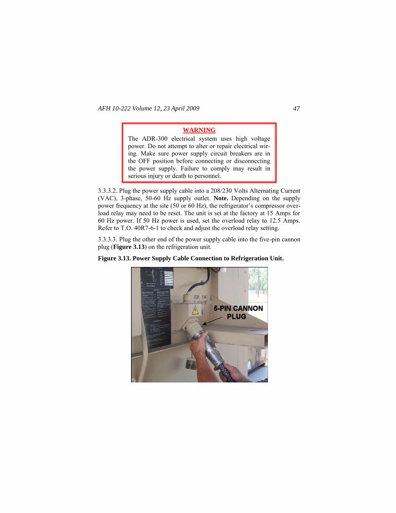
3.3.3.3. Plug the other end of the power supply cable into the five-pin cannon plug (Figure 3.13) on the refrigeration unit.
Figure 3.13. Power Supply Cable Connection to Refrigeration Unit.
WARNING
The ADR-300 electrical system uses high voltage power. Do not attempt to alter or repair electrical wir-ing. Make sure power supply circuit breakers are in the OFF position before connecting or disconnecting the power supply. Failure to comply may result in serious injury or death to personnel.

AFH 10-222 Volume 12, 23April 2009
48
3.3.3.4. Plug the container power supply cord into the container power con-nector assembly (Figure 3.14).
Figure 3.14. Container Power Supply Cord Connection.
3.4. Operation. Before starting or operating the ADR-300, look for signs of trouble with the refrigerator unit. Often you can feel, smell, hear, or see many problems before they get worse. Perform the ―Before Operation‖ PMCS to ensure the refrigerator and its associated equipment are in good working con-dition.
3.4.1. Perform “Before Operation” PMCS. PMCS verifies that all compo-nents are correctly installed and secure and there is no visible damage to the frame or components that could cause unsafe operation. Perform ―Before Operation‖ PMCS according to procedures in Table 3.2.

AFH 10-222 Volume 12, 23 April 2009 49
Table 3.2. ADR-300 “Before Operation” PMCS.
Check: Unserviceable If:
Surfaces: Inspect all interior and exterior surfaces of the container for cracks, breaks, or dents.
A hole passes through the inner and outer skins, holes in either skin ex-ceed 1 inch in length or 1/2 inch in depth, or any crack exceeds 1-inch in length.
Sling Ring Brackets: Inspect the sling ring brackets for separation from the container.
Deformed, separated, or missing sling ring brackets are discovered.
Exterior Drain Plug and Hose: Inspect the exterior drain plug, and inspect the hose to confirm it is properly restrained.
The drain plug or hose is missing or hose is improperly restrained.
Cargo Restraint Rails: Inspect cargo restraint rails for deforma-tion, cracks, breaks, or corrosion.
Missing, damaged, or corroded cargo restraint rail is identified.
Container Door Panel: Open the door—note any resistance in the door locks or hinges.
Close the door and lock the main and secondary handles—note any resistance to swinging or to move- ment of the door locks.
Inspect the perimeter of the door to ensure the seal lays flat against the doorframe everywhere.
Any moving part does not move smoothly or the door does not form a proper seal around its entire peri-meter.

AFH 10-222 Volume 12, 23April 2009
50
Check: Unserviceable If:
Container Shelf Assembly: When installed, verify all shelves are present, properly supported at the corners, and not damaged or deformed.
Verify the shelves and rubber spacers rest against the container interior surfaces.
Confirm the bottom shelves are se-cured to the floor.
Any shelf is damaged or not prop-erly supported. Vertical supports are damaged. Screws or other at-tachment hardware is missing.
Light Fixture, Switch, and Light
Indicator: Inspect the light switch inside the container for damage.
Verify power is connected to the refrigeration unit and the contain-er.
Switch on the light to confirm the light illuminates and that the exte-rior light indicator is lit.
Switch off the light.
The light switch, light fixture, or light indicator is damaged or non-operational.
Refrigeration Unit Interior:
Inspect the inside (evaporator) section. Note any damage to the housing.
Inspect for refrigerant oil residue.
There is visible damage to the housing or evidence of refrigerant oil on exterior surface.

AFH 10-222 Volume 12, 23 April 2009 51
Check: Unserviceable If:
Refrigeration Unit Exterior:
Inspect the eight mounting bolts holding the unit on the container for security of attachment.
Inspect the sling rings for breaks, cracks, or deformation.
Inspect all wires for condition and proper attachment at both ends.
Verify the refrigeration unit is plugged into a 208/230 VAC, 50-60 Hz, 3-phase electrical source.
Inspect the condenser section en-closure for damage and security of attachment.
Inspect refrigerant lines for dam-age or evidence of refrigerant oil residue.
Verify the control box is securely attached to the base plate and free of cracks or other damage. Con-firm the wire connecting the con-trol panel to condenser section is in good condition and securely connected at both ends.
Inspect the condensation drain to ensure it is not blocked and there is no visible damage.
There is missing attachment hard-ware; loose or unsecured refrigera-tion unit; damaged or missing sling rings; damaged, frayed, or loose wires; damaged or loose condenser housing; damaged or leaking refri-gerant lines; damaged or loose con-trol panel; damaged breaker box.
There is evidence of refrigerant oil on exterior surface.

AFH 10-222 Volume 12, 23April 2009
52
Check: Unserviceable If:
Refrigerator Operation: (After starting the refrigerator unit ac-cording to paragraph 3.4.2.) Note the interior temperature.
Set the setpoint to 32º F (if the interior temperature is lower than 32º F, set the setpoint at least 5o below the interior temperature). Confirm that the unit operation indicator light glows green (cool-ing mode).
After the interior temperature has dropped below 36o F, start a ma-nual defrost cycle. Confirm that the defrost indicator light is on.
Set the thermostat setpoint to ap-proximately 50o F. Confirm that the unit operation indicator light glows red (heating mode).
The refrigerator does not enter the heating mode when the setpoint is above the interior temperature or cooling mode when setpoint is be-low the interior temperature. The defrost mode does not start when the manual defrost is in-itiated.
3.4.2. Start the Refrigeration Unit. After connecting the power supply and performing PMCS, start the refrigeration unit as follows:
3.4.2.1. Press the ON/OFF key on the unit controller. The ON/OFF light will remain illuminated and the unit will start, stop, and defrost automatically while maintaining the desired setpoint temperature.
3.4.2.2. Enter the setpoint by pressing and holding the setpoint key. The set-point temperature will be displayed in the display window for 10-15 seconds. Adjust the setpoint up or down by rotating the thermostat dial while the set-point is displayed.

AFH 10-222 Volume 12, 23 April 2009 53
3.4.2.3. Release the setpoint key. The display will return to the inside temper-ature after approximately 10-15 seconds. Note. Do not move the thermostat dial after adjusting the setpoint. The setpoint may be changed without the setpoint temperature being displayed.
3.4.2.4. Verify that the new setpoint was entered by pressing the setpoint key and checking the display.
3.4.3. Select Temperature Scale. The temperature readings can be displayed in either the Celsius scale or the Fahrenheit scale. To change the temperature scale on the controller display, proceed as follows:
3.4.3.1. Open the control box; pull out the controller, and slide open the cover on the back of the controller as shown in Figure 3.15 and Figure 3.16.
Figure 3.15. Controller Removal.

AFH 10-222 Volume 12, 23April 2009
54
Figure 3.16. Opened Back Cover on Controller.
3.4.3.2. Place dip switch 3 (Figure 3.17) in the desired position: Up (ON) for Celsius, and Down (OFF) for Fahrenheit. Afterwards, replace the cover, re-position the controller, and close the control box.
Figure 3.17. Dip Switch 3 in Down/OFF (Fahrenheit) Position.

AFH 10-222 Volume 12, 23 April 2009 55
3.4.4. Perform Operational Checks. Once the refrigeration unit is operating, make periodic checks according to Table 3.3 and lubricate refrigeration con-tainer parts according to Table 3.4.
Table 3.3. ADR-300 Operational PMCS.
Check: Unserviceable If:
Refrigeration Operation: Check that the interior temperature is hold-ing at the setpoint. Check that the air pathways are not blocked. Check accumulation of frost on inside unit.
Temperature is not maintained, pathways are blocked, or there is significant frost accumulation.
Refrigeration Container: Check the entire container for damage. Check the door fit and seal. Check door hinges and handles for lubrica-tion. Check for loose or missing hardware.
There are damaged container pa-nels or loose, missing, or dam-aged components or there is bind-ing or restricted movement of moving parts.
Table 3.4. ADR-300 Lubrication Requirements.
Components Lubricant Frequency
Door Hinges Light Oil Lubricant Weekly (or as required)
Door Locks Light Oil Lubricant Weekly (or as required)
Roof Access Steps Light Oil Lubricant Weekly (or as required)
3.4.5. Unusual Operating Conditions. Several environmental conditions can present special challenges to ADR-300 operation. They may include high humidity, low and high ambient temperatures, blowing sand or dust, snow, or other conditions.
3.4.5.1. High Humidity Conditions. High humidity may increase the rate at which frost accumulates on the evaporator coil. Avoid opening and closing the cargo door more than necessary. This will reduce the amount of humid air

AFH 10-222 Volume 12, 23April 2009
56
entering the container and the resulting accumulation of frost. Although the refrigeration unit is designed to defrost automatically, users should monitor the level of frost accumulation on the evaporator (interior) coil. If a signifi-cant level of frost is observed, begin a manual defrost cycle or adjust the de-frost timer according to T.O. 40R7-6-1.
3.4.5.2. Low and High Ambient Temperatures.
3.4.5.2.1. Low ambient temperatures enhance the performance of the refrige-ration unit; however, those conditions also cause plastic and rubber elements to stiffen and become brittle. Handle plastic and rubber parts gently in cold weather to avoid cracking or breaking. The door gasket may freeze to the doorframe; therefore, pull firmly and steadily to separate the gasket from the frame when opening the container door.
3.4.5.2.2. High ambient temperatures result in high refrigeration loads while degrading the performance of the refrigeration unit. Therefore, the user should try to minimize the loads on the system in this environment. Locate the ADR such that it is shaded from the midday sun. Avoid opening the container door and do not hold the door open longer than necessary. Avoid, to the greatest extent possible, placing large, warm cargoes in the container all at once.
3.4.5.3. Blowing Sand and Dust. Sand and dust tend to damage moving parts and accumulate on the refrigeration coils, particularly the condenser (outside) coil. Clean the coil surfaces regularly with water and remove accu-mulations of sand and dust by blowing compressed air over them. Also, avoid opening and closing the container door more than necessary. During short periods of high levels of airborne sand or dust, the ADR may be shutdown and the refrigeration unit covered to reduce the amount of sand and dust drawn into the unit. If this is done, shutdown the ADR before covering the refrigeration unit and carefully monitor the container interior temperature to be sure it remains at safe levels for the stored cargo.
3.4.5.4. Snow. Accumulations of snow or ice around the condenser air inlet or outlet may reduce the airflow through the coil and degrade the perfor-mance of the refrigeration unit. Keep these openings as clear as possible to promote good airflow. Note. Do not permit more than 12 inches of snow to accumulate on the container roof. Accumulations of snow elsewhere on or

AFH 10-222 Volume 12, 23 April 2009 57
around the unit should not affect the ADR-300 performance. Users are ad-vised to keep controls, displays, and gauges clear of snow accumulation to make routine ADR-300 operation and monitoring easier.
3.4.6. Emergency Procedures. There are two occasions when the ADR-300 may pose a danger to personnel and require emergency procedures; personnel locked inside the container and rapid loss of refrigerant.
3.4.6.1. Personnel Locked Inside the Container. Individuals locked inside the container with the refrigeration unit running or not, face a potential emer-gency. Personnel trapped inside the container may suffocate due to lack of fresh air or may suffer hypothermia (low body temperature) if exposed to low inte-rior temperatures. To prevent these dangers, the container door can be opened from the inside at any time, even if the handle is padlocked. To open the door from the inside, simply rotate the interior door handle unit assemblies to the vertical position and push the plunger. This will release the door latch and al-low the door to swing open.
3.4.6.2. Rapid Loss of Refrigerant. A rapid and total loss of refrigerant may result from a broken refrigerant line and may displace air, causing possible suffocation. In the event of a sudden loss of refrigerant, personnel should exit the container immediately and leave the door open to allow the refrigerant to dissipate.
3.4.6.3. Other emergencies may occur that do not present a hazard to person-nel. These situations involve the potential loss or spoilage of cargo due to an inability of the system to maintain the required interior temperature. If the system is unable to maintain the preset interior temperature, refer to operator troubleshooting procedures in T.O. 40R7-6-1.
3.5. Shutdown Procedures. To shutdown, turn OFF the refrigeration unit at the control panel located inside the control box and unplug the power supply cable from the refrigeration unit.
3.6. Preparation for Storage or Shipment. When ADR-300 operations are completed, empty and clean the container, and prepare it for storage or ship-ment. If cargo will be stored inside the container during shipment, comply

AFH 10-222 Volume 12, 23April 2009
58
with paragraph 3.6.3.1 and ensure that the cargo is stored according to load-ing procedures in T.O. 40R7-6-1 and other applicable guidance.
3.6.1. Cleaning. Wash both the interior and exterior of the container and al-low the interior to dry thoroughly before closing it for storage. The exterior of the container and refrigeration unit may be washed with a low-pressure water spray. Ensure the ADR is disconnected from its primary power supply before washing the exterior, and be careful to avoid spraying water up into the con-denser section of the refrigeration unit. The interior of the container should be cleaned only when the refrigerator is turned off and the interior is approx-imately room temperature (68 to 77o F). Use a low-pressure water spray and mild detergent to clean the container surfaces and shelves, and be careful to avoid spraying water up into the evaporator coil. Do not soak electrical com-ponents, and drain all water from the container through the floor drain.
3.6.2. Storing. If the ADR-300 will be unused for an extended period, take steps to preserve and protect the system. Basic steps include cleaning the unit and elevating it off the ground or floor to allow air circulation under the con-tainer. Place the container on at least three evenly-spaced 4- x 4-inch beams laid across the width of the container. This helps to prevent moisture accumu-lation and corrosion. If possible, store the container on a slight slope to en-hance drainage. When storing ADR-300s, the containers may be stacked no more than two high. Lifting with a crane requires a hoist of 10,000-lb (4,536 kg) capacity and slings connected to the lifting rings in the upper corners of the container. Ensure that the sling lines create an angle of more than 45 de-grees with the container roof to prevent structural damage to the ADR. Fail-ure to comply may result in damage to the equipment.
WARNING
When stacking one ADR-300 on top of another, en-sure both units are aligned so that front and side walls of top unit are flush with front and side walls of lower unit. This will ensure that the lower unit will support the weight of the top unit. Failure to comply may re-sult in serious injury or death to personnel.

AFH 10-222 Volume 12, 23 April 2009 59
3.6.3. Shipping. The ADR-300 may be shipped in either an operational (re-frigerated) or non-operational condition. The container is designed to retain cold temperatures inside for several hours without a source of power. The ADR may be transported by truck, rail, internal airlift, and external airlift (helicopter sling) according to procedures in T.O. 40R7-6-1. Regardless of which transportation method is used, be sure not to exceed the lifting, hoist-ing, or transporting weight limits of equipment and vehicles.
3.6.3.1. Shipping in Operational Condition. If the container will be shipped with refrigerated cargo, ensure the designated gross weight limit is not ex-ceeded and complete the following steps.
3.6.3.1.1. Restrain all cargo items as described in T.O. 40R7-6-1 and turn off the interior light.
3.6.3.1.2. If the cargo will not be damaged by freezing and time permits, re-duce the setpoint temperature to a low level and allow the cargo to cool to that temperature.
WARNING
For ADR-300 systems that will be airlifted, door handle unit assemblies should be left unlocked, using only the main door handle to hold the door closed. This will allow pressure relief, if necessary, during flight. Failure to comply may cause serious injury or death to person-nel. Failure to comply may also cause equipment to implode or explode, causing hazard to the aircraft.
CAUTION
Do not exceed the designated weight limit. The con-tainer’s gross weight should never exceed 10,000 lbs (4,536 kg). Failure to comply may cause damage to the container or cargo handling equipment.

AFH 10-222 Volume 12, 23April 2009
60
3.6.3.1.3. Lock the cargo door and confirm the seal is satisfactory.
3.6.3.1.4. Confirm that the drain plug located under the door on the front face of the ADR-300 is installed.
3.6.3.1.5. As near as possible to the departure time, shutdown the refrigera-tion unit, disconnect the power cord from the source of power, and move the container where necessary.
3.6.3.2. Shipping in Non-Operational Condition. If the ADR-300 is to be moved in a non-operational condition, complete the following steps:
3.6.3.2.1. Turn off the interior light, shutdown the refrigeration unit, and dis-connect the power supply cord.
3.6.3.2.2. Clean the container interior according to paragraph 3.6.1.
3.6.3.2.3. Restrain all loose items inside the container to the restraint rings on the floor of the container, close and lock the cargo door, and move the con-tainer where necessary.

AFH 10-222 Volume 12, 23 April 2009 61
Chapter 4
FIELD DEPLOYABLE ENVIRONMENTAL CONTROL UNIT
(FDECU)
4.1. General Information. The FDECU is the primary air conditioning and heating unit supporting BEAR sets (Figure 4.1). The unit provides cooled and dehumidified air, or heated air, through flexible ducts into various types of portable shelters and containers. The FDECU is available in several different models; however, the images and information presented in this chapter is ge-neric in nature and not for any particular model, unless specified.
Figure 4.1. Field Deployable Environmental Control Unit (FDECU).
4.2. Characteristics and Features. The FDECU is a horizontally configured, electric-motor-driven heat pump. The unit will circulate and filter air and provide fresh make-up air as desired. It can be used while directly exposed to the environment and will operate with filter blower overpressure systems developed for use in Chemical, Biological, Radiological, and Nuclear (CBRN) environments. Total airflow is 2200 standard cubic feet per minute

AFH 10-222 Volume 12, 23April 2009
62
(SCFM), and make-up airflow is adjustable between 0 and 500 SCFM. The unit uses 14 pounds of R-134A refrigerant as a normal charge and delivers cooling capacity at 55,000 BTUH to 67,000 BTUH and heating capacity at 47,000 BTUH to 84,000 BTUH. The FDECU weighs a maximum of 700 to 800 pounds (depending on model type), and a forklift will be needed to posi-tion the unit. Major features include the systems, subassemblies, and support-ing equipment items identified in Figure 4.2. Descriptions of several key features are listed in subsequent paragraphs.
Figure 4.2. FDECU Major Components.
4.2.1. Master Control Panel. The master control panel (Figure 4.3) is incor-porated into the FDECU and provide all the operator controls needed to start, operate, and stop the system, as well as maintain the desired shelter air tem-perature.

AFH 10-222 Volume 12, 23 April 2009 63
Figure 4.3. Master Control Panel.
4.2.2. Remote Control Panel and Cable. The remote control panel has a 35-foot cable that is normally mounted inside the shelter (Figure 4.4). It pro-vides duplicate controls and indicators, similar to the master control panel.
Figure 4.4. Remote Control Panel and Cable Routed Inside Shelter.

AFH 10-222 Volume 12, 23April 2009
64
4.2.3. Electrical Power Input Cable. A 25-foot electrical power input cable is used to connect the FDECU to a source of electrical power for operation. The cable should be connected to a 3-phase, 208 VAC, 60 Amp power supply with ground. The power cable is stored on the inside of the FDECU when not in use.
4.2.4. Sight Glass. The sight glass, or liquid refrigerant indicator shown in Figure 4.5, permits visual inspection of the liquid refrigerant passing through the system and is used to aid in diagnosing possible refrigerant system prob-lems. The sight glass also contains an indicator that changes color depending upon the amount of moisture contained in the refrigerant.
Figure 4.5. Sight Glass (or Liquid Refrigerant Indicator).
4.2.5. Air Filter. The replaceable air filter is located in the return air flange assembly (Figure 4.6). The filter removes dust and debris from the shelter air as it passes through the FDECU.

AFH 10-222 Volume 12, 23 April 2009 65
Figure 4.6. Replaceable Air Filter Located Inside Return Air Flange.
4.2.6. Electrical Resistance Heaters Assembly. This assembly contains two banks of electrical resistance heaters that are used (independently or togeth-er) to supplement the refrigerant system heating capacity in cold weather (Figure 4.7).
Figure 4.7. Supplemental Electric Resistance Heaters.

AFH 10-222 Volume 12, 23April 2009
66
4.3. Set-Up Procedures.
4.3.1. Siting. Place the FDECU in an operating position near the shelter or desired structure. The unit must be placed on a relatively level surface (not exceeding 5 degrees in any direction) and be positioned so that sides and top are at least 4 feet from any obstruction (Figure 4.8). Placement must also allow water to drain from the bottom in the winter during outside coil defrost cycles. When positioning the unit next to the shelter, be sure that the ducts can be connected with smooth bends and will not be kinked.
Figure 4.8. Siting FDECU.
WARNING
The FDECU is heavy (700-800 lbs) and requires an appropriate lifting device to move. Personal injury can result if moved without the aid of a lifting device.

AFH 10-222 Volume 12, 23 April 2009 67
4.3.2. Configuration. The FDECU can be configured for use in either normal environmental conditions or CBRN environmental conditions (Figure 4.9). Use in CBRN environmental conditions requires using a CBRN adapter kit and CBRN filter blower assemblies. Refer to T.O. 35E9-314-1, Operator,
Unit, Direct Support and General Support Maintenance Manual, Field Dep-
loyable Environmental Control Unit (FDECU), for specific CBRN hardening procedures.
Figure 4.9. FDECU Sample Configuration.
WARNING
The FDECU cover is heavy. Be sure the cover retain-ing rod is in place and properly secured with the hair pin cotter. Injury can occur if cover drops.

AFH 10-222 Volume 12, 23April 2009
68
4.3.3. Unpacking and Assembling. When unpacking the FDECU, examine the equipment for damage and the presence of all required components (Figure 4.10).
Figure 4.10. Unpacked FDECU Components.
4.3.3.1. Begin unpacking by raising and securing the cover. Make sure the hair cotter pin securing the cover is installed into the rod from the top accord-ing to Figure 4.11.
4.3.3.2. Unpack Input Power Cable. Carefully uncoil the input power cable assembly and extend the cable outside the unit. Make sure the cable rests in the end panel notch.
4.3.3.3. Unpack Air Ducts. Remove the two insulated flexible air ducts. The return air duct is 7 feet long and the supply air duct is 9 feet long.
4.3.3.4. Remove Shipping Cover From Return Air Volute Assembly. Un-clip the quick-release pin and remove the flange assembly (Figure 4.12). Turn the flange counterclockwise to remove. Take out and store the shipping

AFH 10-222 Volume 12, 23 April 2009 69
cover, and reassemble the flange assembly (Figure 4.13). Install the flange assembly into the volute assembly with the perforated duct collar facing out. Align the slots and turn clockwise to lock in place.
Figure 4.11. Hair Cotter Pin Installation.
Figure 4.12. Return Air Flange Assembly Removal.

AFH 10-222 Volume 12, 23April 2009
70
Figure 4.13. Removal of Shipping Cover from Return Air Volute.
4.3.3.5. Remove Shipping Cover From Supply Air Volute Assembly.
Loosen the six screws securing the supply panel (Figure 4.14), and remove the supply panel from the lower retaining clips. Slide the shipping cover out of the supply panel and store for reuse.
4.3.3.6. Unpack Condensate Drain Hose. Uncoil the condensate drain hose, and pass it through the hole in the frame. Pull the entire length of hose from the unit while leaving it attached to the volute assembly.
4.3.3.7. Adjust Heater Barrel and Reinstall Supply Panel. Unclip the four quick release pins on the heater barrel (Figure 4.15). Carefully pull the heater barrel out to stops (approximately 4 inches). Install the supply panel into the lower retaining clips, and then slip the panel over the heater barrel while aligning the mounting holes. Secure the supply panel by reinstalling the six screws.

AFH 10-222 Volume 12, 23 April 2009 71
Figure 4.14. Loosen Supply Panel Screws.
Figure 4.15. Removal of Quick Release Pins on Heater Barrel.

AFH 10-222 Volume 12, 23April 2009
72
4.3.3.8. Mount Remote Control Box in Shelter. Release the two wing nut fasteners and any fastener straps securing the cable. Lay the cable and remote control box outside the FDECU. Ensure the cable rests in the end panel notch. Route the remote control box inside the shelter then mount the box at eye level away from drafts or supply air opening. Seal any opening made in the shelter. If a mounting bracket is not available in the shelter, the bracket used to store the remote control box in the FDECU can be removed and mounted inside the shelter using standard hardware or clamps. If the bracket from the FDECU is removed, make sure to reinstall the bracket attachment hardware (screws, nuts, washers, etc.) back into the holes on the FDECU.
4.3.3.9. Connect Air Ducts. Install the 9-foot-long supply air duct between the heater barrel and the shelter supply duct connector. Be sure the duct is installed with the airflow direction arrow pointed toward the shelter. After-ward, secure the duct by tightening the two clamps. Install the 7-foot-long return air duct between the flange assembly and shelter return duct connector. The airflow direction arrow should be pointed toward the FDECU. The perfo-rated holes in the flange assembly (Figure 4.16) are intended to provide from zero to 500 SCFM of fresh outside air to the shelter depending on how many, if any, holes are exposed. At least four or five rows of perforated holes should be exposed to assure a continuous supply of fresh make-up air. Position the air duct on the flange assembly as necessary and secure into place by tighten-ing the clamps.
4.3.3.10. Connect Input Power Cable Assembly. Connect the input power cable to a 208 VAC, 3-phase, 50/60 Hertz, 60 Amp power supply with ground (Figure 4.17).
CAUTION
Ice could form on the inside coil if airflow is re-stricted. Ducts must be installed as straight as possible with a minimum number of bends. Unit performance will be affected and damage to equipment could occur if airflow is restricted.

AFH 10-222 Volume 12, 23 April 2009 73
Figure 4.16. Perforated Holes and Clamps on Return Air Flange.
Figure 4.17. FDECU Connected to 208 Volts AC Power Supply.

AFH 10-222 Volume 12, 23April 2009
74
4.4. Operation. Operation of the FDECU is not complicated; however, be-fore commencing operations, operators must perform ―Before Operation‖ PMCS to determine if the unit will function properly.
4.4.1. Perform “Before Operation” PMCS. PMCS is essential to the effi-cient operation of the FDECU and is necessary to prevent possible damage that may occur through neglect or failure to observe warning signs and symp-toms in a timely manner. Perform ―Before Operation‖ PMCS according to procedures in Table 4.1. If the FDECU has been in storage prior to use, also perform the ―Weekly‖ and ―Monthly‖ PMCS according to Table 4.2 and Table 4.3 prior to operating the unit.
Table 4.1. FDECU “Before Operation” PMCS.
Check: Unserviceable If:
Flexible Air Ducts: Inspect for worn or torn spots and secure at-tachment to unit and shelter. (Reat-tach as necessary.)
Air ducts cannot be securely at-tached to unit or shelter. Torn to the point that it will not carry air to shelter.
Outside Coil: Inspect for dirt or obstruction to coil. (Remove ob-struction or clean as necessary.)
Dirt or obstruction cannot be re-moved.
Outside Fan: Check to ensure fan is securely attached to motor and ensure nothing obstructs normal fan blade rotation.
Fan is loose on motor shaft.
Liquid Refrigerant Indicator
(Sight Glass): Inspect liquid indi-cator for cracks and note center indicator color.
Liquid refrigerant indicator port is cracked or center indicator color is yellow or red, depending on type of liquid indicator being used.
Control Panel: Check for damage to knob, switch, or push button.
Control panel damage would pre-vent safe operation of the equip-ment.

AFH 10-222 Volume 12, 23 April 2009 75
Table 4.2. Weekly PMCS.
Check: Unserviceable If:
Power Cable: Inspect for frayed or damaged insulation over visible length of cord and at entry point to unit.
Power cable is frayed or damaged.
Interconnecting Wiring: Inspect for frayed or damaged insulation over visible portion of wires.
Any wire is frayed or damaged.
Table 4.3. Monthly PMCS.
Check: Unserviceable If:
Cover, Screens, and Panels: Check for dirt or obstruction of screens. (Remove obstruction or clean as necessary.) Check for loose or miss-ing attaching hardware.
Cover or screen is missing, loose, or damaged to the point of interfer-ing with safe operation.
Air Filter: Remove air filter and check for cleanliness and damage. (Replace as necessary.)
Return air filter is dirty enough to cause obstruction to airflow.
Outside Surface of Unit: Inspect for cracks, dents in the frame, or panels. Check for chipped or miss-ing paint and any evidence of cor-rosion.
Cracks or dents in the frame inter-fere with safe operation.
Identification Plates: Check that identification plates are securely attached to unit and can be easily read.

AFH 10-222 Volume 12, 23April 2009
76
4.4.2. Start and Operate the FDECU. After connecting the power supply and performing PMCS, make a final check to confirm the drain hose will drain away from the unit and that the FDECU cover is down and secured by the latch pins. Also, verify the fan cover door is open and secured with the quick release pin. Start the unit according to procedures in the following pa-ragraphs. Note. Before starting FDECU-2 models, refer to T.O. 35E9-314-1 for operating limits due to compressor warm-up delays.
4.4.2.1. Choose which control panel will be used (unit or remote), then posi-tion the Control Selection toggle switch to either ―THIS PANEL‖ or ―REMOTE BOX‖ as highlighted in Figure 4.18.
Figure 4.18. Control Selection Toggle Switch (FDECU-2 Panel).
WARNING
Dangerous and lethal voltage is used in the operation of the FDECU. Personal injury or death can result if power is not isolated from the unit during maintenance when panels and doors are open.

AFH 10-222 Volume 12, 23 April 2009 77
4.4.2.2. To operate in the vent mode, push the vent mode button (Figure
4.18) to activate the inside blower. The ON indicator light will illuminate and the shelter air will begin to circulate. This will not control the temperature.
4.4.2.3. To operate in the climate control mode (heating and air conditioning); set the temperature knob (Figure 4.18) to about the one o’clock position or to ―normal operation‖ on some models. This position is approximately 75o F. Then push the climate control button (Figure 4.18) to activate the automatic temperature control system. The ON indicator light will illuminate. In some instances, immediate operation may be prevented by the control logic time-out circuit. If this occurs, do not turn the unit off; it should start automatically within 5 minutes. Note. For FDECU-2 models, if the compressor warm up indicator light (Figure 4.18) is illuminated, the compressor is still warming and will not operate. However, the unit will operate in vent or resistance heat mode.
4.4.2.4. When the system is fully operating in the climate control mode, use the temperature knob to increase or decrease the shelter air temperature with-in a range of 60o F to 100o F. The unit will maintain the temperature to within 5o F of the setting. If the unit is operating in the cooling mode after start up, do not adjust the temperature knob for several hours until the shelter air tem-perature stabilizes.
4.4.2.5. If the inside coil ices over, operate the unit in the vent mode until the coil de-ices. For severe coil ice over, operate the unit in the heat mode (ap-proximately 10-15 minutes) to de-ice the coil.
4.4.3. Perform “During Operation” Checks. Once the FDECU is operating, make periodic checks according to Table 4.4.
WARNING
Rotating parts are used in operating the FDECU. Do not install or adjust return air duct when inside blower is operating. The flange assembly can disengage and come off, resulting in personal injury.

AFH 10-222 Volume 12, 23April 2009
78
Table 4.4. FDECU “During Operation” PMCS.
Check: Unserviceable If:
Liquid Refrigerant Indicator
(Sight Glass): Inspect the liquid refrigerant indicator port for con-stant bubbles, foam, or to see if the center indicator color is red or yel-low, depending on type of indica-tor being used.
The liquid refrigerant indicator port shows constant bubbles or foam or if the center indicator col-or is red or yellow, depending on the type of indicator being used.
Condensate Drain Hose: When in cooling mode, check that water is dripping from the hose end. If wa-ter is dripping from other areas, notify unit maintenance.
4.4.4. Operation under Unusual Conditions. Like many HVAC/R systems, environmental conditions may affect the operational efficiency of the FDECU. Conditions such as extreme heat or cold, snow, dust or sand storms, and CBRN agents or materials can present special challenges during FDECU operation.
4.4.4.1. Extreme Heat. In extreme hot weather conditions, the load or strain on the FDECU can be significant. The best way to reduce demand on the system is to open and close the shelter as little as possible. If fresh outside make-up air is not required, position the return air duct over the perforated holes on the unit’s return air flange. Do not maintain the shelter temperature any lower than necessary. If possible, provide shade over the unit and always ensure there are no obstructions to airflow through the FDECU.
4.4.4.2. Extreme Cold and Snow. Just as during extreme heat conditions, in extreme cold weather conditions, open and close the shelter as little as possi-ble. Position the return air duct over the perforated holes on the return air flange if outside make-up air is not required. Make sure any openings in the shelter are sealed, and try not to maintain shelter temperature higher than necessary. In snowy conditions, the area around the unit should be kept clear to prevent obstructions caused by snow build-up. Additionally, when the unit

AFH 10-222 Volume 12, 23 April 2009 79
defrosts ice from the outside coil, water drains from the bottom of the unit and could cause ice to build up and collect in this area. If not previously ac-complished, it may be necessary to raise the unit to prevent water collection.
4.4.4.3. Dust and Sand Storms. Although the FDECU does not require any special protection procedures against conditions such as dust and sand storms, the unit should be cleaned more frequently than under normal conditions. If fresh outside make-up air is not required, position the air duct over perforated holes on the return air flange. The return air filter will also require cleaning more frequently.
4.4.4.4. CBRN Agents or Materials. Operating the FDECU in a CBRN en-vironment requires the attachment of special blowers, filters and adapters. The unit should be operated according to instructions supplied with the CBRN adapter kit. Refer to T.O. 35E9-314-1 for specific procedures when configuring and operating the FDECU with CBRN equipment.
4.5. Shutdown Procedures. FDECU shutdown procedures depend on which mode the unit is operating. If operating in the heating and air conditioning mode, push the climate control button to deactivate the automatic temperature control system. If operating in the ventilation mode, push the vent mode but-ton to deactivate the inside blower. In both instances, the ON indicator light will go out after the button is pushed. Afterward, unclip the quick release pin on the fan cover door. Close and secure the door with the door fasteners.
4.6. Preparation for Storage or Shipment. When FDECU operations are completed, several actions need to be accomplished before storing or shipping the unit. First, operate the FDECU in the vent mode for approximately one hour to ensure that any condensate is drained from the unit and to dry out the inside coil and ducts. Then, complete the following steps:
CAUTION
Extreme cold can cause electrical wire leads and insulation to become brittle. Do not disturb electrical wiring that has been exposed to ex-tremely low temperatures because damage to wire leads or insulation could occur.

AFH 10-222 Volume 12, 23April 2009
80
4.6.1. Shutdown the FDECU and disconnect it from the power source.
4.6.2. If applicable, disconnect and secure CBRN adapter kit according to T.O. 35E9-314-1.
4.6.3. Loosen the clamps and remove both air ducts. Be sure the ducts are dry, and then set the ducts and clamps aside for storage inside the unit.
4.6.4. Raise and secure the FDECU cover. Make sure the hair cotter pin se-curing the cover is installed into the rod from the top.
4.6.5. If used, remove the remote control panel from the shelter and secure it inside the FDECU. Remember, if the remote control storage bracket from the FDECU was used to mount the remote control panel inside the shelter, it must be installed back into the unit.
4.6.6. Install the supply and return air shipping covers in their reverse order of removal. Make sure the heater barrel is pushed inside the supply air volute and properly secured with the four quick-release pins. Position and secure both shipping covers with cover screws.
4.6.7. Store the condensate drain hose in the reverse order it was removed. Be sure there is no water inside the hose and that the hose is coiled around the heater barrel for storage.
WARNING
The FDECU cover is heavy. Be sure the cover retain-ing rod is in place and properly secured with the hair cotter pin. Injury can occur if the cover drops.
WARNING
Rotating parts and lethal voltage levels are used in operating the FDECU. Be sure power source is dis-connected after shutdown. Injury or death can occur if connected to power source.

AFH 10-222 Volume 12, 23 April 2009 81
4.6.8. Pack the air ducts down into the FDECU, and then carefully coil the input power cable assembly around the ducts. Drape the power cable connec-tor down into the air ducts to hold them down.
4.6.9. Close the FDECU cover and secure with the cover latch pins.

AFH 10-222 Volume 12, 23April 2009
82
Chapter 5
130K MULTI-FUELED PORTABLE HEATER
5.1. General Information. The 130K Portable Heater (Figure 5.1) is the main heater for BEAR sets. Its principle purpose is to provide heated air for shelters and working areas. As indicated by its name, the heater has a heated air output of 130,000 BTUH at 0o F and is capable of burning several types of fuel. The overall design concept of the heater is modular. All major compo-nents are easily accessible for maintenance and can be easily removed and installed. Because the heater uses a fuel-fired system, operators should exer-cise extreme care and observe all technical order warnings and cautions to ensure safe operation.
Figure 5.1. 130K Heater.
5.2. Characteristics and Features. The unit is a fully enclosed, skid-mounted heater with three temperature ranges: high, medium, and low. The basic design of the heater features a separate electric-motor-driven oil burner with separate blower for combustion air and an electric-motor-driven heater

AFH 10-222 Volume 12, 23 April 2009 83
blower. It uses 120 Volts, 50/60 Hz generator or commercial power to oper-ate the oil burner and combustion air blower. The heater will deliver hot air at a minimum of 1000 cubic feet per minute (CFM) and at temperatures ranging from 80o F to 180o F. The heated air output performance of the 130K heater makes it ideal for use during extremely cold conditions. Other external and internal features include the following.
5.2.1. External Features: Listed below and illustrated in Figure 5.2.
5.2.1.1. Covers. The sheet metal covers protect internal components of the heater from open environments. Top covers for the combustion chamber/heat exchanger and blower are easily removed, allowing easy access to major components. The control panel/burner compartment has a hinged cover panel.
5.2.1.2. Frame. The heater is constructed with an upper and lower frame. The lower frame has an integrated skid for easy maneuverability, and fork-lift boxes that are accessible from the long sides of the heater.
5.2.1.3. Fuel Tank and Fuel Gauge. The all-metal, on-board fuel tank is located in the lower frame and has a storage capacity of 21 gallons. The fuel gauge is a mechanical, float-type gauge and is part of the fuel fill cap. The gauge is easily viewed without opening any heater covers.
5.2.1.4. Air Inlet and Outlet. Shelter or facility air returns to the heater through the circulation air inlet, and heated air is supplied to the shelter or facility via the heated air outlet.
5.2.1.5. Power Cable. The power cable extends from the burner compartment and plugs into a 120 Volt, 20 Amp maximum power source. The green indi-cator light on the control panel verifies the presence of voltage.
5.2.1.6. Exhaust Outlet. Combustion fumes, which are completely separated from heated air, exit through the exhaust outlet at the top of the heater.

AFH 10-222 Volume 12, 23April 2009
84
Figure 5.2. External Features.
5.2.2. Internal Features: Listed below and illustrated in Figure 5.3.
5.2.2.1. Fuel Feed Hose (External Tank). The heater is equipped with an al-ternative fuel feed hose for attachment to an external fuel tank. The on-board or external fuel tank is selected using a 3-way valve attached to the fuel lines.
5.2.2.2. Fuel Filter. The fuel filter lies between the 3-way valve and the fuel injection pump. It filters fuel from both the external and on-board fuel tanks before the fuel is pumped into the burner nozzle.

AFH 10-222 Volume 12, 23 April 2009 85
5.2.2.3. Fuel Burner and Burner Control Unit. The fuel burner is a stan-dard, commercial fuel burner. It consists of an electric motor to drive the combustion air blower and high-pressure fuel injection pump, and an igni-tion transformer, both of which are visible and accessible from outside of the burner frame. The burner control unit (BCU) is a microprocessor-equipped control unit located inside the heater control box. The BCU con-trols the function and safety of the fuel burner.
Figure 5.3. Internal Features.
5.2.2.4. Main Air Blower. The heater blower operates at a nominal 1000 CFM and forces heated air through the heater housing, around the burner chamber, and through the heat exchanger. Thermal energy is transferred from the hot surfaces of the combustion components into the circulating air. The heated air is supplied to the facility via the flexible ducts. The blower’s electric motor is 120 Volt, 50/60 Hz, running at 1700 Revolutions per Minute (RPM).

AFH 10-222 Volume 12, 23April 2009
86
5.2.2.5. Combustion Chamber. The heater combustion chamber houses the fuel burner tube and provides an exit route for exhaust gases. Flame is contained inside the burner chamber, thus only hot exhaust gases exit the chamber to the heat exchanger.
5.2.2.6. Heat Exchanger. Hot combustion exhaust gases from the combus-tion chamber pass through the heat exchanger during burner operation. Thermal energy is conducted and transferred into discharge air, which is blown past the heat exchanger channels by the main air blower. Exhaust gases remain completely separated from the heated air, and the gases exit through the exhaust outlet and into open air.
5.2.2.7. External Thermostat and Carbon Monoxide (CO) Monitor. The external thermostat and CO Monitor (Figure 5.4) are critical components of the heater unit. The external thermostat remotely controls heater operation when the mode switch on the control panel is set to ―AUTO.‖ The CO Monitor continuously checks the level of carbon monoxide within the shel-ter or facility and sounds an alarm if permitted levels are exceeded. The heater unit should never be used without a properly located and functioning CO Monitor. The thermostat/monitor should hang in a central position within the shelter or facility being heated.
Figure 5.4. External Thermostat and CO Monitor.

AFH 10-222 Volume 12, 23 April 2009 87
5.2.2.8. Control Panel. The heater control panel is the top portion of the heater control box, and it is located just underneath the burner/control panel access door. The control panel contains the heater control switch, heater mode switch, panel light and switch, heater hour meter, flame failure reset button, and digital display. Figure 5.5 and Table 5.1 highlight the compo-nent functions on the control panel. Table 5.2 describes the meaning of digital display messages.
Figure 5.5. Heater Control Panel.

AFH 10-222 Volume 12, 23April 2009
88
Table 5.1. 130K Heater Control Panel Components and Function.
Item Function
Heater Control Switch
Used to select temperature settings (Low, Medium, or High) or ―Vent‖ for unheated airflow only. Combus-tion begins once a temperature setting is selected.
Heater Mode Switch
Used to select the operating mode (Manual or Auto) for the heater unit. The ―Auto‖ mode is for remote thermostat-controlled operation, and the ―Manual‖
mode is for constant outlet temperature.
Function Digital Display
Displays the output air temperature (in 5o F incre-ments), heater operation status, burner (failure and overheat) alarm, and problem diagnostic messages (see Table 5.2).
Flame Failure Reset Button Reactivates the burner in case of a flame failure.
Circuit Breaker Reset Switch
Resets the heater’s circuit breaker when the circuit breaker is tripped off.
Control Panel Light Switch
Activates the control panel light to illuminate the panel and operating instructions located on the panel door.
Heater Hour Meter
Displays the total number of hours of heater opera-tion.
Main ON Indicator Light Indicates that power is supplied to the heater unit.

AFH 10-222 Volume 12, 23 April 2009 89
Table 5.2. Heater Control Panel Display Messages.
Display Meaning
OFF
The Heat Control Switch in ―STOP‖ position and the power source is connected. The heater is cool/cold. The burner is off. The main air blower is off after cooling. The power ca-ble can be disconnected.
AFC
The Heat Control Switch has been turned from HIGH, MED, or LOW output setting to the ―STOP‖ position. After-cooling (AFC) is in process. The main air blower is still on. DO NOT disconnect power cable before display shows ―OFF.‖
FAN The Heat Control Switch is in the ―VENT‖ position. The main air blower is blowing. There is No heating--the burner is off.
LO The Heat Control Switch is in ―HIGH/MED/LOW.‖ Air outlet temperature is 39° F or less. The burner is ON but has not yet raised the outlet temperature above 39° F.
LO (Blink-ing)
The burner has been on for at least five minutes and the out-let air temperature is below 32° F. Probable cause of this condition is either sensor/sensor wiring problem or burner failure. Correct this error by turning the heat control switch briefly to ―STOP,‖ then back to the heating position. Refer to Troubleshooting in T.O. 35E7-3-4-1, Operation and
Maintenance Instructions with Illustrated Parts Break-
down, Heater, 130K Multi-Fueled, Portable, Duct Type, if this procedure does not solve the problem.
HI (Blink-ing)
Overheated outlet air (225° F or above) situation, sensor problem or sensor wiring problem. Forced main air blower cooling occurs. Correct this error by turning the heat control switch briefly to ―STOP,‖ then back to the heating position. Refer to Troubleshooting in T.O. 35E7-3-4-1 if this proce-dure does not solve the problem.

AFH 10-222 Volume 12, 23April 2009
90
5.3. Set-Up Procedures. Specific steps to set up the heater are as follows.
5.3.1. Siting the 130K Heater. Place the heater in an operating position near the shelter or desired structure (Figure 5.6). Select a location that is as level as possible not exceeding eight degrees in any direction. Attempt to avoid locating the heater in the path of normal shelter or facility pedestrian traffic , and leave adequate room for operation, maintenance, and refueling of the heater unit. When positioning the unit next to the desired facility, be sure to position air ducts in a manner that avoids sharp bends or kinks. Kinks in the air ducts impede airflow and decrease efficiency.
Figure 5.6. 130K Heater Sited Near Tent.
5.3.2. Preparation for Use and Preliminary Adjustments. When preparing the heater for use, complete the following checks and preliminary adjustments before operating the heater unit.
CAUTION
When using a forklift to move the heater, ensure the forklift tines are in the forklift pockets provided and extend completely under the heater unit. Failure to comply may result in serious equipment damage.

AFH 10-222 Volume 12, 23 April 2009 91
5.3.2.1. Examine the equipment for damage and the presence of all required parts. Ensure the exhaust extension is positioned inside the exhaust ring on top of the heater (Figure 5.7). Inspect for damaged gauges and meters, loose connections or mountings, loose or missing hardware, and frayed insulation or wiring. Check all tubing and hoses for secure connections and for any evi-dence of damage.
Figure 5.7. Exhaust Extension (Stack) Installation.
WARNING
Do not add fuel until the heater has properly cooled according to instructions in heater shutdown proce-dures. Failure to comply may result in equipment damage, bodily injury, or death.
WARNING
Do not wear metal frame glasses, rings, watches, or other metal jewelry while working on electronic equipment.

AFH 10-222 Volume 12, 23April 2009
92
5.3.2.2. Check the fuel level to ensure the fuel supply is sufficient for the planned duration of operation. If not, fill the on-board fuel tank as follows. First, remove the fuel tank filler cap and install the fuel filler strainer inside the filler tube. Then fill the fuel tank with the appropriate fuel type (see Table
5.3). Do not fill the tank any higher than the lower end of the filler tube. Af-terward, remove and store the fuel strainer in its holder inside the burner compartment. Reinstall the filler cap when completed.
Table 5.3. 130K Heater Operating Fuel Types.
Fuel Types
Diesel DF-1 and DF-2 Jet Fuel Jet A and JetA1, JP-4, JP-5, and JP-8
5.3.2.3. If using an external fuel tank, uncoil the alternative fuel feed hose, and then connect it to the external fuel tank. Turn the three-way fuel valve (Figure 5.8) to select fuel from the external tank.
Figure 5.8. Fuel Three-Way Valve Positions.

AFH 10-222 Volume 12, 23 April 2009 93
5.3.2.4. Connect the air outlet and recirculation ducts (Figure 5.9) between the heater and shelter according to the shelter instructions. Secure the hea-ter’s duct end adapters in the frame by a slight clockwise rotation. If re-quired, introduce fresh air into the circulation by opening the fresh air collar (Figure 5.10) as follows: Loosen the collar retainer bolt and turn the collar to the desired position (adjusting clockwise results in more fresh air).
Figure 5.9. Air Duct Connection.
Figure 5.10. Fresh Air Adjustment.

AFH 10-222 Volume 12, 23April 2009
94
5.3.2.5. Connect the external thermostat/CO monitor cable into the receptacle under the control box. Bring the thermostat/CO monitor combination into the space being heated. Do not place the external thermostat in the direct vicinity of the warm air discharge duct. Instead, hang the thermostat/CO monitor in a central position. When power is applied, make sure the green ―POWER‖ light is ON in the CO monitor and the alarm sounds for a few seconds, indicating that the monitor is activated. If the green ―POWER‖ light does not illuminate when power is applied to the CO monitor or the alarm fails to sound when the ―TEST‖ button is pushed, change the monitor before using the heater. CO monitor function can also be tested by briefly pushing the ―TEST‖ button. The alarm should sound when the button is pushed.
WARNING
Never operate the heater without a functional carbon monoxide (CO) monitor properly connected and lo-cated. Failure to comply may result in bodily injury or death.
WARNING
The CO monitor is a delicate, calibrated instrument, so do not attempt any repairs. Change the monitor if it is defective. Failure to comply may result in bodily in-jury or death.
WARNING
Dangerous voltages are present at electric system con-nectors. Ensure power is OFF (power cable discon-nected) prior to connecting or disconnecting cables or wires.

AFH 10-222 Volume 12, 23 April 2009 95
5.4. Operation. The heater operating controls and indicators are located on the control panel. Access the heater controls by opening the burner/control panel compartment cover on the top, right side of the heater. Note. Do not operate the heater without air ducts installed, except during maintenance.
5.4.1. Connect the power cable plug into a 120 Volt, 60/50 Hz, 20 Amp (max-imum) power source. Open the control panel cover and verify the green indi-cator light is illuminated.
5.4.2. Once power is supplied to the heater, set the mode switch on the con-trol panel to either ―AUTO‖ for remote thermostat-controlled operation or ―MANUAL‖ for constant outlet temperature. If the ―MANUAL mode is selected, turn the heat control switch to the desired outlet temperature (see Table 5.4). If in the ―AUTO‖ mode, turn the heat control switch to ―HIGH‖ and set the desired temperature on the remote thermostat.
5.4.3. Make sure the remote thermostat is located in a central place within the space to be heated. Note. Do not place the external thermostat in the direct vicinity of the warm air discharge duct.
WARNING
If the heater is operated for maintenance inside a building, exhaust gases must be vented to the outside by means of a suitable exhaust vent system. Do not apply a forced-draft (suction) type exhaust system directly to the heat exchanger exhaust. Utilize an exhaust hood or locally manufacture an exhaust vent adapter to mate with facilities exhaust venting system. The exhaust vent adapter must provide a minimum of 6 inches of free air space between the upper end of the exhaust stack and the hood. Failure to comply could result in bodily injury or death.
WARNING
The heater is unsafe for operation in explosive atmos-pheres. Attempting to start the heater in an explosive atmosphere may result in bodily injury or death.

AFH 10-222 Volume 12, 23April 2009
96
Table 5.4. Heat Control Switch Settings.
Switch Position Output Air
VENT Unheated Ventilating Air LOW TEMP 80o F – 140o F MED TEMP 100o F – 160o F HIGH TEMP 120o F – 180o F
5.5. Shutdown Procedures. Always position the mode switch to ―MANUAL‖ before shutting down the heater. Then turn the heat control switch to ―STOP‖ and allow the heater to perform its after-cooling function (ACF). When the display message reads ―OFF‖ and the blower has stopped, disconnect the heater power cable. After that, close and latch the control panel cover. In the event of an emergency or fire, disconnect the power cable to perform an emergency heater shutdown. Although this action may damage the heater’s combustion components, it is the safest and quickest way to terminate heater operations in an emergency.
5.6. Preparation for Storage or Shipment. Perform the following procedures when preparing the heater for storage or shipment.
WARNING
Heater can generate enough heat in certain locations to cause severe burns upon physical contact. Allow heater to cool before touching.
CAUTION
When shutting down the heater, do not disconnect the power cable from the power source until the panel dis-play message reads ―OFF.‖ Disconnecting the cable be-fore the display reads ―OFF‖ may damage combustion components.

AFH 10-222 Volume 12, 23 April 2009 97
5.6.1. Disconnect the power cable from the power source. Coil the cable and stow it in the heater burner compartment.
5.6.2. Drain the fuel from the fuel tank by opening the drain plug on the tank (Figure 5.11) and draining the fuel contents into a suitable container.
Figure 5.11. Fuel Tank Drain.
5.6.3. Remove the air ducts from the heater. Compress ducts and secure them with hook and loop provided inside ducts (Figure 5.12) to secure in transport configuration.
Figure 5.12. Ducts Secured with Hook and Loop.
5.6.4. Cover the heater air inlet and outlet adapters with the adapter covers (Figure 5.13).

AFH 10-222 Volume 12, 23April 2009
98
Figure 5.13. Adapter Cover Installation.
5.6.5. Remove the external thermostat from the shelter. Coil the cable and insert the cable and thermostat into heater burner compartment.
5.6.6. If the external fuel feed hose was used, remove the hose from the external fuel container, coil the hose, then stow the hose in the burner compartment.
5.6.7. Remove the flue gas exhaust extension, and cover the heater exhaust outlet with the steel cap provided.
5.6.8. The remaining packing procedures are dependent on the method of shipment. When preparing the heater unit for air shipment, make sure the fuel tank cap is installed and properly tightened and the air vent hole is open and unobstructed. This action will permit pressure equalization during altitude and temperature changes. Refer to T.O. 35E7-3-4-1 and T.O. 35-1-4, Processing and Inspection of Aerospace Ground Equipment for Storage and
Shipment, for more information on preparing the heater unit for storage or shipment.

AFH 10-222 Volume 12, 23 April 2009 99
Chapter 6
INFORMATION COLLECTION, RECORDS, AND FORMS
6.1. Information Collections. No information collections are created by this publication.
6.2. Records. The program records created as a result of the processes pre-scribed in this publication are maintained in accordance with AFMAN 33-363 and disposed of in accordance with the AFRIMS RDS located at Hhttps://www.my.af.mil/gcss-af61a/afrims/afrims/.
6.3. Forms (Adopted and Prescribed).
6.3.1. Adopted Forms. AF IMT 847, Recommendation for Change of Publi-
cation.
6.3.2. Prescribed Forms. No prescribed forms are implemented in this pub-lication.
MICHAEL A. AIMONE, SES
Assistant DCS/Logistics, Installations, & Mission Support

AFH 10-222 Volume 12, 23April 2009
100
Attachment 1
GLOSSARY OF REFERENCES AND SUPPORTING INFORMATION
References
AFI 10-209, RED HORSE Program, 13 May 2008
AFI 10-210, Prime Base Engineer Emergency Force (BEEF) Program, 21 March 2008
AFI 32-1064, Electrical Safe Practices, 25 May 2006
AFMAN 33-363, Management of Records, 1 March 2008
AFPAM 10-219, Volume 5, Bare Base Conceptual Planning Guide, 1 June 1996
AFPAM 10-219, Volume 7, Expedient Methods, 9 June 2008
T.O. 35-1-4, Processing and Inspection of Aerospace Ground Equipment for
Storage and Shipment, 30 September 1995
T.O. 35E7-3-4-1, Operation and Maintenance Instructions with Illustrated
Parts Breakdown, Heater, 130K Multi-Fueled, Portable, Duct Type, 1 July 2007
T.O. 35E7-4-27-1, Operator's, Unit and Direct Support Maintenance Manual,
Heater, Water, Liquid Fuel, M-80 and M-8, 30 June 2005
T.O. 35E9-314-1, Operator, Unit, Direct Support and General Support
Maintenance Manual, Field Deployable Environmental Control Unit
(FDECU), 1 February 2006
T.O. 35E35-3-1, Operation, Storage, Inspection and Maintenance Instructions
with Illustrated Parts Breakdown, Shave Stand Bare Base, Erection, Part No.
8611370, 1 September 1987
T.O. 35E35-4-1, Operation, Storage, Inspection and Maintenance Instructions
with Illustrated Parts Breakdown, Shower Facility Bare Base, Erection, 1 September 1987

AFH 10-222 Volume 12, 23 April 2009 101
T.O. 35E4-169-1, Operation, Storage, Inspection and Maintenance Instruc-
tions with Illustrated Parts Breakdown, Harvest Falcon/Eagle Kitchen Facili-
ty, Erection, 30 May 2003
T.O. 35E4-169-21, Operation and Maintenance Instructions with Illustrated
Parts Breakdown, Initial Deployment Kitchen, 2 November 1999
T.O. 35E4-169-31, Erection, Operation, Storage, Inspection and Mainten-
ance Instructions with Illustrated Parts Breakdown, Bare Base Harvest Fal-
con/Eagle Electric Kitchen with Mess Kit Laundry, 1 May 2006
T.O. 40R7-6-1, Operator's, Unit, and Direct Support Maintenance Manual,
Advanced Design Refrigerator, 300 Cubic Foot, (ADR-300), 7 February 2007
Abbreviations and Acronyms
AC—Alternating Current
ACF—After-Cooling Function
ADR—Advanced Design Refrigerator
AF—Air Force
AFCESA—Air Force Civil Engineer Support Agency
AFH—Air Force Handbook
AFI—Air Force Instruction
AFIMS—Air Force Incident Management System
AFMAN—Air Force Manual
AFPAM—Air Force Pamphlet
AFRIMS—Air Force Records Information Management System
AFS—Air Force Specialty
AFSC—Air Force Specialty Code
BCU—Burner Control Unit

AFH 10-222 Volume 12, 23April 2009
102
BEAR—Basic Expeditionary Airfield Resources
BTU—British Thermal Units
BTUH—British Thermal Units per Hour
CBRN—Chemical, Biological, Radiological, and Nuclear
CO—Carbon Monoxide
FDECU— Field Deployable Environmental Control Unit
GPM—Gallons per Minute
HPCO—High-Pressure Cut-Out
HQ—Headquarters
HVAC/R—Heating, Ventilation, Air Conditioning, and Refrigeration
Hz—Hertz
IMT—Information Management Tool
IR—Infrared
LBS—Pounds
LPCO—Low-Pressure Cut-Out
MAJCOM—Major Command
OPR—Office of Primary Responsibility
PMCS—Preventive Maintenance Checks and Services
PRIME BEEF—Prime Base Engineer Emergency Force
PSI—Pounds per Square Inch
QD—Quick Disconnect
RDS—Records Disposition Schedule
RED HORSE—Rapid Engineer Deployable Heavy Operational Repair Squadron Engineer

AFH 10-222 Volume 12, 23 April 2009 103
RPM—Revolutions per Minute
SCFM—Standard Cubic Feet per Minute
TO—Technical Order
UV—Ultraviolet
VAC—Volt Alternating Current Terms
Air Force Civil Engineer Support Agency (AFCESA)—A field operating agency (FOA) located at Tyndall Air Force Base, Florida. The Directorate of Contingency Support (HQ AFCESA/CEX) acts as the Air Force program manager for Base Civil Engineer (BCE) Contingency Response Planning.
Bare Base—An installation having minimum essential facilities to house, sustain, and support operations to include, if required, a stabilized runway, taxiways, and aircraft parking areas. A bare base must have a source of water that can be made potable. Other requirements to operate under bare base con-ditions form a necessary part of the force package deployed to the bare base.
Basic Expeditionary Airfield Resources (BEAR)—Facilities, equipment, and basic infrastructure to support the beddown of deployed forces and air-craft at austere locations; a critical capability to fielding expeditionary aero-space forces. Also known as BEAR, the resources include tents, field kitch-ens, latrine systems, shop equipment, electrical and power systems, runway systems, aircraft shelters, and water distribution systems needed to sustain operations.
Chemical, Biological, Radiological and Nuclear (CBRN) Defense—The methods, plans, procedures, and training required to establish defense meas-ures against the effects of attack by nuclear weapons or chemical and biologi-cal agents.