overview of the telecommunications network - uniroma2.it · telecommunication networks basic...
TRANSCRIPT
Overview of the
Telecommunications Network
1
15
Telecommunications Network

Telecommunication Networks
Basic purpose of a telecommunications network: transmit user information
in any form to another user of the network.
Many forms of networks, such as voice or data; subscribers may use different
access network technologies to access the network, for example, fixed or cellular
telephones.
Different services, such as data, fixed, or cellular telephony service.
2
Different services, such as data, fixed, or cellular telephony service.
(1) Transmission
(2) Switching
(3) Signaling.
16
Three technologies needed for communication through the telephone
network (POTS, plain old telephone service):

Transmission
Transmission is the process of transporting information between end points
of a system or a network.
Transmission systems use four basic media for information transfer from one point to
another:
1. Wire-pair (copper) cables, such as those used in telephone subscriber lines (access
network)
2. Optical fiber cables, such as those used in high-data-rate transmission in
3
2. Optical fiber cables, such as those used in high-data-rate transmission in
telecommunications networks (especially in transport networks)
3. Radio waves, such as microwave radio links, cellular telephones and satellite
transmission
4. Free-space optics, and infrared communications (limited application, e.g. PC-to-PC
short range links).
17Fiber optics Twisted pairs Radio links

Manual Switching4
18
A manual telephone exchange (1896)
An old rotary dial telephone
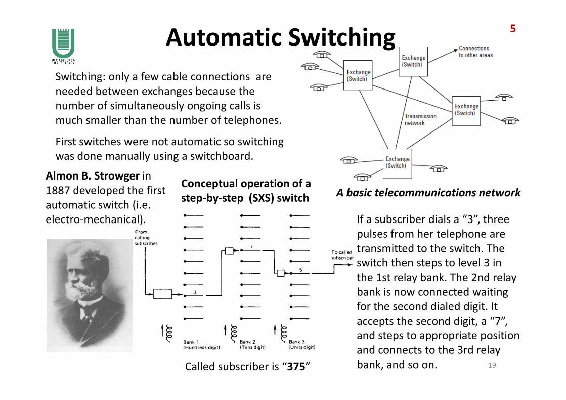
Automatic Switching
Switching: only a few cable connections are
needed between exchanges because the
number of simultaneously ongoing calls is
much smaller than the number of telephones.
A basic telecommunications network
Almon B. Strowger in
1887 developed the first
automatic switch (i.e.
First switches were not automatic so switching
was done manually using a switchboard.
Conceptual operation of a
step-by-step (SXS) switch
5
automatic switch (i.e.
electro-mechanical).
19
step-by-step (SXS) switch
If a subscriber dials a “3”, three
pulses from her telephone are
transmitted to the switch. The
switch then steps to level 3 in
the 1st relay bank. The 2nd relay
bank is now connected waiting
for the second dialed digit. It
accepts the second digit, a “7”,
and steps to appropriate position
and connects to the 3rd relay
bank, and so on.Called subscriber is “375”
Signaling
Signaling is the mechanism that allows network entities (customer premises
or network switches) to establish, maintain, and terminate sessions in a network.
Signaling examples on subscriber lines (i.e. between telephone and its central office):
• Off-hook condition
6
• Dial
• On-hook condition
Signaling needed between exchanges as well because most calls have to be
connected via more than just one exchange.
20
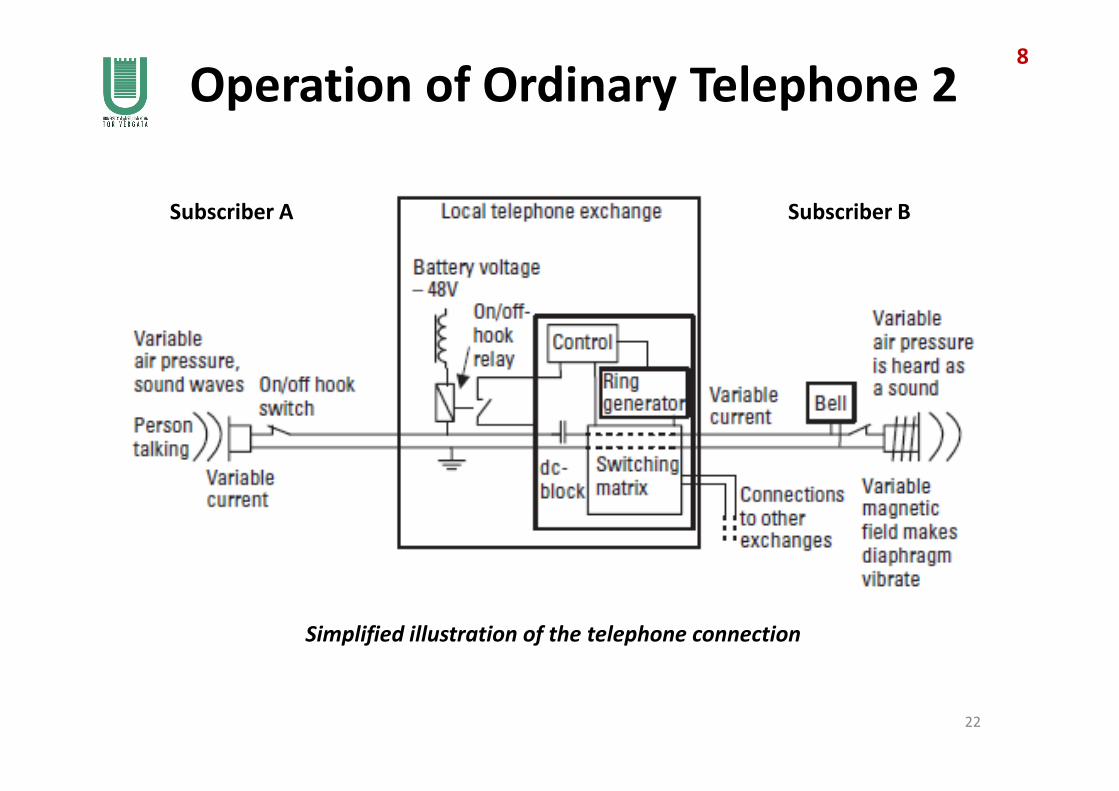
Operation of Ordinary Telephone 1
Local exchanges have a large-capacity battery that keeps the exchange and subscriber
sets operational for a few hours if the supply of electricity is cut off.
7
A subscriber line, also called “local loop”, which carries speech signals is a twisted pair.
Power supply comes from the exchange site: basic telephone service independent of
the local electric power network.
Local loop
Telephone
21
In its simplest form a telephone consists of:
(a) one microphone and one earphone, combined into a single handheld unit
(b) means of signaling the exchange when a call is to be made
(c) means of sending to the exchange the ‘address’ information of the called subscriber
(d) an incoming call alarm
(e) means of signaling the exchange that the call has been answered.
Telephone
Operation of Ordinary Telephone 28
Subscriber A Subscriber B
22
Simplified illustration of the telephone connection
Operation of Ordinary Telephone 39
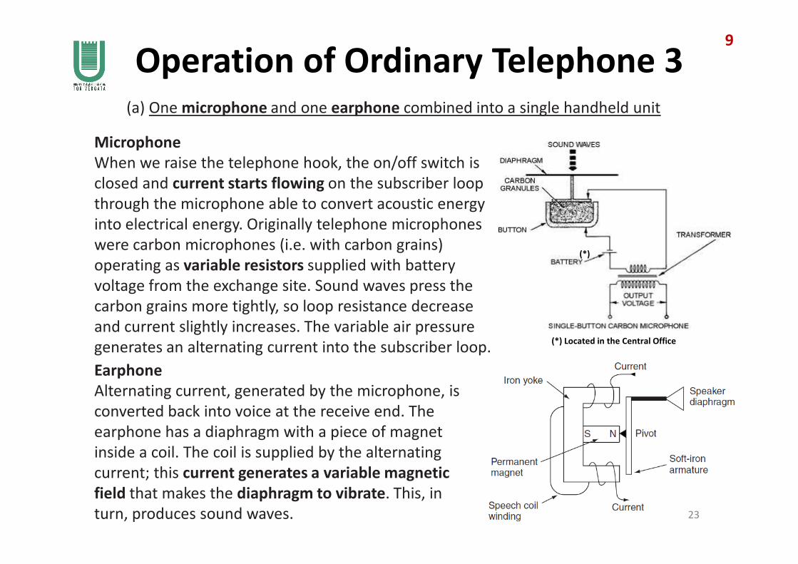
(a) One microphone and one earphone combined into a single handheld unit
Microphone
When we raise the telephone hook, the on/off switch is
closed and current starts flowing on the subscriber loop
through the microphone able to convert acoustic energy
into electrical energy. Originally telephone microphones
were carbon microphones (i.e. with carbon grains)
operating as variable resistors supplied with battery
voltage from the exchange site. Sound waves press the
(*)
23
Earphone
Alternating current, generated by the microphone, is
converted back into voice at the receive end. The
earphone has a diaphragm with a piece of magnet
inside a coil. The coil is supplied by the alternating
current; this current generates a variable magnetic
field that makes the diaphragm to vibrate. This, in
turn, produces sound waves.
voltage from the exchange site. Sound waves press the
carbon grains more tightly, so loop resistance decrease
and current slightly increases. The variable air pressure
generates an alternating current into the subscriber loop.(*) Located in the Central Office

Operation of Ordinary Telephone 410
(b) Means of signaling the exchange when a call is to be made
Signaling functions include the detection of on/off-hook condition and dialing.
Each telephone has a switch that indicates an on- or off-hook condition. When the hook is
raised, the switch is closed and current starts flowing.
This is detected by a relay giving information to the control unit in the exchange.
(c) Means of sending to the exchange the ‘address’ information of the called subscriber
The control unit activates signaling circuits, which then receive dialed digits from subscriber
who initiates a call (Subscriber A). The control unit in the telephone exchange controls the
switching matrix that connects the speech circuit through to the called subscriber
24
switching matrix that connects the speech circuit through to the called subscriber
(Subscriber B). Connection is made according to the numbers dialed by Subscriber A.
(d) An incoming call alarm
When the call is being routed to Subscriber B, the telephone exchange supplies to the
subscriber loop a ringing voltage and the bell of Subscriber B’s telephone starts ringing.
(e) Means of signaling the exchange that the call has been answered
The ringing voltage is switched off immediately when an off-hook condition is detected
on the loop of subscriber B, and then an end-to-end speech circuit is connected and the
conversation may start.

Summary of Signaling ProcedureSwitch open in the on-hook condition and closed when the hook is off
• indicates to the telephone exchange when a call is to be initiated
• prepare to receive dialed digits
Local loop closed and opened according to the dialed digits, and the number of
current pulses is detected by the exchange
11
Subscriber signaling25
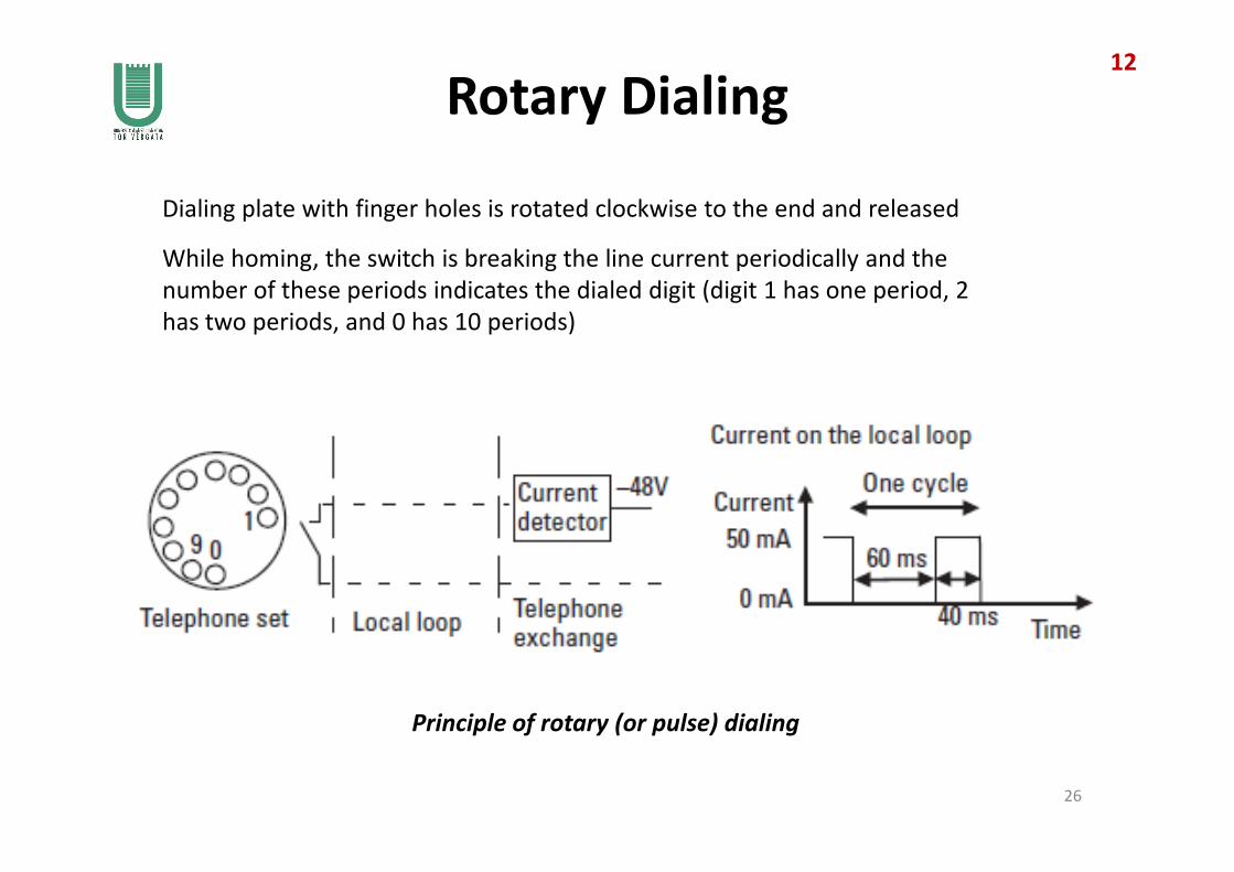
Rotary Dialing
Dialing plate with finger holes is rotated clockwise to the end and released
While homing, the switch is breaking the line current periodically and the
number of these periods indicates the dialed digit (digit 1 has one period, 2
has two periods, and 0 has 10 periods)
12
Principle of rotary (or pulse) dialing
26
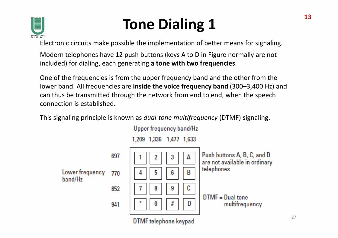
Tone Dialing 1Electronic circuits make possible the implementation of better means for signaling.
Modern telephones have 12 push buttons (keys A to D in Figure normally are not
included) for dialing, each generating a tone with two frequencies.
One of the frequencies is from the upper frequency band and the other from the
lower band. All frequencies are inside the voice frequency band (300–3,400 Hz) and
can thus be transmitted through the network from end to end, when the speech
connection is established.
This signaling principle is known as dual-tone multifrequency (DTMF) signaling.
13
This signaling principle is known as dual-tone multifrequency (DTMF) signaling.
27
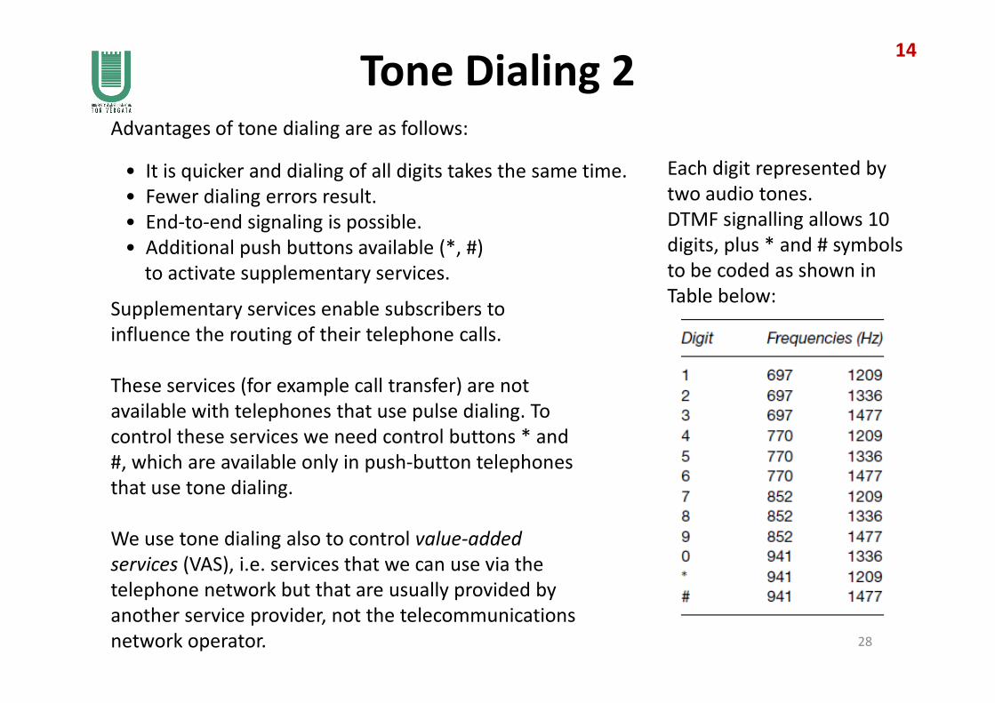
Tone Dialing 2Advantages of tone dialing are as follows:
• It is quicker and dialing of all digits takes the same time.
• Fewer dialing errors result.
• End-to-end signaling is possible.
• Additional push buttons available (*, #)
to activate supplementary services.
Supplementary services enable subscribers to
influence the routing of their telephone calls.
Each digit represented by
two audio tones.
DTMF signalling allows 10
digits, plus * and # symbols
to be coded as shown in
Table below:
14
These services (for example call transfer) are not
available with telephones that use pulse dialing. To
control these services we need control buttons * and
#, which are available only in push-button telephones
that use tone dialing.
We use tone dialing also to control value-added
services (VAS), i.e. services that we can use via the
telephone network but that are usually provided by
another service provider, not the telecommunications
network operator. 28
2 Wires and 4 Wires Circuits
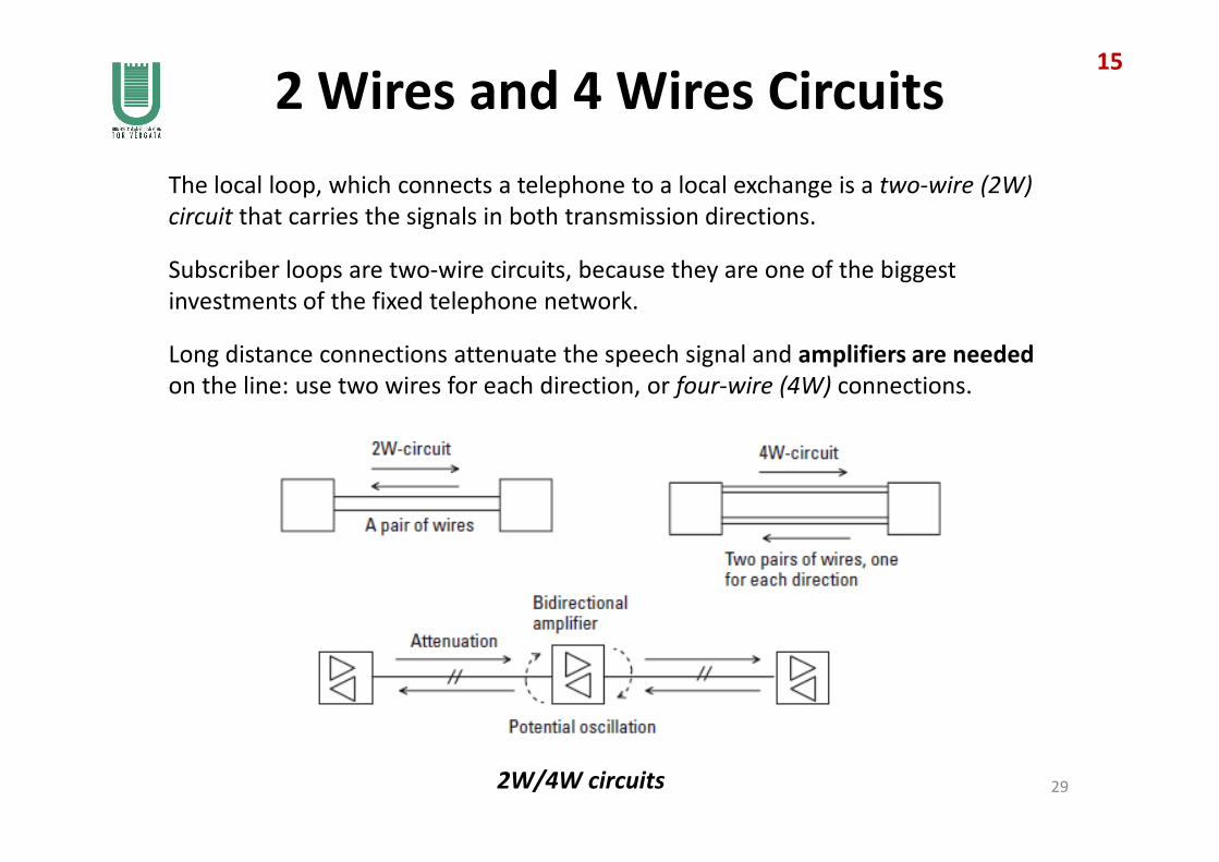
The local loop, which connects a telephone to a local exchange is a two-wire (2W)
circuit that carries the signals in both transmission directions.
Subscriber loops are two-wire circuits, because they are one of the biggest
investments of the fixed telephone network.
Long distance connections attenuate the speech signal and amplifiers are needed
on the line: use two wires for each direction, or four-wire (4W) connections.
15
2W/4W circuits 29
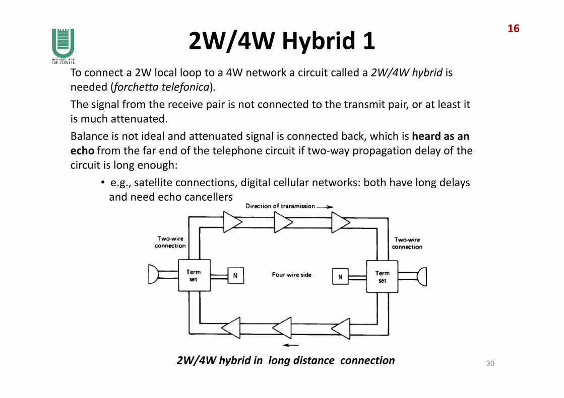
2W/4W Hybrid 1To connect a 2W local loop to a 4W network a circuit called a 2W/4W hybrid is
needed (forchetta telefonica).
The signal from the receive pair is not connected to the transmit pair, or at least it
is much attenuated.
Balance is not ideal and attenuated signal is connected back, which is heard as an
echo from the far end of the telephone circuit if two-way propagation delay of the
circuit is long enough:
• e.g., satellite connections, digital cellular networks: both have long delays
and need echo cancellers
16
2W/4W hybrid in long distance connection
and need echo cancellers
30

2W/4W Hybrid 2The 2W/4W hybrid performs the following operations:
• separates the transmitting and receiving signals
• matches the impedance of the 2W local loop to the network circuit
• provides a loss to signals arriving on the receiving path, preventing
them from entering the transmitting path, which would cause echo.
In every subscriber set quite the same principle as the 2W/4W hybrid is used to
attenuate the subscriber’s own voice from the microphone to the earphone.
17
31Generation of echo signal in a 2W/4W connection