overview of building elevator systems - · pdf fileoverview of building elevator systems ......
TRANSCRIPT

PDHonline Course M376 (4 PDH)
Overview of Building Elevator Systems
2012
Instructor: A. Bhatia, B.E.
PDH Online | PDH Center5272 Meadow Estates Drive
Fairfax, VA 22030-6658Phone & Fax: 703-988-0088
www.PDHonline.orgwww.PDHcenter.com
An Approved Continuing Education Provider

www.PDHcenter.com PDH Course M376 www.PDHonline.org
Overview of Building Elevator Systems
For most people residing in urban cities, elevators have become an integral part of their daily
life. Simply stated, an elevator is a hoisting or lowering mechanism, designed to carry
passengers or freight, and is equipped with a car and platform that typically moves in fixed
guides and serves two or more landings. The elevators can be broadly classified as either
electric traction type or hydraulic type.
• Traction elevators have an elevator car and counterweight attached to opposite ends
of hoist ropes. The hoist ropes pass over a driving machine that raises and lowers the
car. Traction elevators run on load-bearing rails in the elevator hoistway. Traction
elevators are most often used in mid-rise and high-rise buildings with five or more
floors.
• Hydraulic elevators, on the other hand, are raised by forcing pressurized oil through a
valve into a steel cylinder located above ground or underground. The pressure forces
a piston to rise, lifting the elevator platform and car enclosure mounted on it. The car is
lowered by opening the valve and allowing the weight of the car to force oil from the
cylinder in a controlled manner. When the valve is closed the car is stopped. Since the
weight of hydraulic elevator cars is borne by the piston, there is no need for a
structural framework or load-bearing rails. Hydraulic elevators are commonly found in
low-rise buildings with two to five floors.
The main design considerations for choosing either electric traction drive or hydraulic for a
particular project are the number of floors, the height of the building, the number of people to
be transported, desired passenger waiting times and frequency of use.
The other mode of vertical building transportation is “Escalator”. It can be described as moving
stairs typically used to carry large number of people at high volumes through a limited no of
floors. These are commonly used in high density areas or where sudden traffic surges are
expected at times; for example at discharge times from offices, railways underground stations,
airport terminals, theaters, shopping malls and departmental stores. In such applications,
escalators will provide shorter travel time than elevators because elevator cars are limited in
size and passengers have to wait longer for the service.
© A. Bhatia Page 2 of 56
In this course we will discuss the key notions pertaining to elevator systems.

www.PDHcenter.com PDH Course M376 www.PDHonline.org
SECTION - 1 GENERAL ELEVATOR PLANNING
Several factors combine to influence the cost of an elevator installation, including the
passenger handling capacity, waiting interval, speed, location, finishes, intelligent group
control safety, and reliability. There are also risks associated with the use of elevators. To
ensure that persons are not stuck in elevators for longer periods of time, or worse that the
elevator does not loose stability and plummet to the basement from a high floor, the engineers
responsible for designing elevators must comply with all statutory codes and standards.
Typical parameters in design of elevators include:
Characteristic of the premises
• Type and use of building;
• Floor plate size and height of the building;
• Size of population and its distribution in the premises;
• Fire safety and regulations;
• The house keeping of the premises.
Circulation Efficiency
• Number of cars and their capacity;
• Location and configuration of elevators in entrance lobby;
• Travel length, number of stops and maximum acceptable waiting time;
• Arrangement with the combination of elevator, escalator and emergency stairs.
Characteristic of the equipment
• Type of transportation systems;
• Rated load and car dimensions;
© A. Bhatia Page 3 of 56
• The speed of the lift/escalator system;

www.PDHcenter.com PDH Course M376 www.PDHonline.org
• The type of motor drive control system of the machine;
• Mode of group supervisory control and safety features;
• Cab enclosure and hoist way door finishes;
• Emergency power supplies and fire protection systems;
• Requirements of the local regulations on vertical transport system.
And so on. There could be over a hundred different possible configurations for your building's
elevators, and each will have its advantages and disadvantages compared with the others.
DEVELOPMENT PROCESS
The design, installation, and use of an elevator system is dictated according to various
standards (aka elevator codes), which may typically be international, national, state, regional
or city based. Building codes, fire regulations, the American Disabilities Act (ADA) and other
Uniform Federal Accessibility Standards (UFAS) are a few examples of these rules to which
the engineers and architects must submit. As far as the specific rules governing the design of
elevators; American Society of Mechanical Engineer's Standard A17.1 (ASME/ANSI A17.1),
CAN/CSA B44 in Canada and EN81 (European standard) provide the detailed criteria.
Note that in most US Jurisdictions, ASME/ANSI A17.1, A17.2, A17.3, A17.5, A18.1 usually
take precedence over all other codes unless specifically advised.
DESIGN ELEMENTS OF ELEVATOR SYSTEMS
Traffic Planning
Elevators’ planning in building projects is dependant on the “traffic analysis” study which
varies according to the type and usage of the building. For example, an office building typically
requires more elevators than an apartment building due to heavier loads & traffic. Elevator
professionals often use building type to assist in recommending solutions based on different
types of building traffic.
© A. Bhatia Page 4 of 56
Traffic analysis is the study of the population distribution and their predicted pattern of flow
within the day. It helps in selecting:
www.PDHcenter.com PDH Course M376 www.PDHonline.org
• The correct number and type of transportation devices;
• The right sizes and speeds of the transportation devices;
• The proper control systems and features to optimize and synchronize traffic flow;
• The optimum layout for the transportation devices and correct positioning in the
building and in relation to one another;
• Easy access to buildings and a smooth flow of people and goods.
The efficiency of an elevator system is defined in terms of the quantity of service (handling
capacity) and quality of service (passenger waiting time).
Handling Capacity:
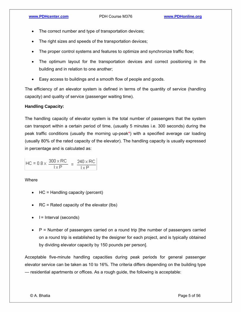
The handling capacity of elevator system is the total number of passengers that the system
can transport within a certain period of time, (usually 5 minutes i.e. 300 seconds) during the
peak traffic conditions (usually the morning up-peak*) with a specified average car loading
(usually 80% of the rated capacity of the elevator). The handling capacity is usually expressed
in percentage and is calculated as:
Where
• HC = Handling capacity (percent)
• RC = Rated capacity of the elevator (lbs)
• I = Interval (seconds)
• P = Number of passengers carried on a round trip [the number of passengers carried
on a round trip is established by the designer for each project, and is typically obtained
by dividing elevator capacity by 150 pounds per person].
© A. Bhatia Page 5 of 56
Acceptable five-minute handling capacities during peak periods for general passenger
elevator service can be taken as 10 to 16%. The criteria differs depending on the building type
— residential apartments or offices. As a rough guide, the following is acceptable:
www.PDHcenter.com PDH Course M376 www.PDHonline.org
• Residential Apartments / buildings: 7 to 9%.
• Premises without specific distribution traffic, such as mixed-tenancy office buildings
with different working hours: 12 to 16%.
• Premises with excessive distribution traffic, such as single tenancy office buildings with
the same working hours: 16 to 25%.
*The up-peak mode is defined as elevator travel from lobby to upper floors. This is considered
the worst case traffic scenario in elevator planning, typically in the morning as people arrive
for work or at the conclusion of a lunch-time period. The reason for employing the up peak
model for sizing the lift is because during up- peak period, the “handling capacity” of the lift
system dominates the degree to which the traffic demand is fulfilled. It is also believed that
systems that can cope with the up-peak period are also sufficient to handle other traffic
conditions.
What is the main purpose of estimating handling capacity?
Since the building space particularly in downtown skyscrapers is precious, the architects
desire to ensure the elevator size fit for the purpose. The purpose of the Handling Capacity
requirement is to allow designer to experiment with different lift system configurations and to
determine the optimum size, speed and number of elevators for a building based on its peak
use periods. Note that the use of smaller lift car will reduce system’s handling capacity unless
more lift cars are installed. The requirement of the handling capacity ensures that the capacity
of the lift system is not being traded off for the interval figures.
If the handling capacity of a lift system is too small, there will be lot of people queuing for the
lifts during up peak. Also, the lift cars will have to go more round trips in order to clear off the
queue. Thus system with too small handling capacity will degrade the quality of service.
Interval:
Interval or waiting interval is the average time, in seconds, between successive lift car arrivals
at the main terminal floor with cars loaded to any level. The interval represents the theoretical
longest time between elevator dispatches from the main lobby.
© A. Bhatia Page 6 of 56
The interval is directly related to passenger waiting times and inversely related to the
number of elevators in a group and is calculated by the following equation:

www.PDHcenter.com PDH Course M376 www.PDHonline.org
Where
• I = Interval
• T = round trip time for one elevator
• n = number of elevators in the group (in lift bank)
An acceptable interval during peak periods for ordinary occupancies can be taken as 25 to 30
seconds. An interval of 30 seconds means that a car will be leaving the lobby every 30
seconds with a load of passengers.
For a fixed handling capacity, large interval means small number of lift cars and large lift car
rated capacity. Lift system with small number of lift cars but large rated capacity will result in
inefficient use of energy during off peak hour. Imagine how energy is wasted during off peak
hours when there are frequent occasions of only a few people traveling in a large lift car.
Round Trip Time
It is the time in seconds for a single car trip around a building, from the time the car doors
open at the main terminal, until the car doors reopen, when the car has returned to the main
terminal after its trip around the building.
The round trip time is estimated by adding together such factors as acceleration and
deceleration rates, full-speed running time, door opening time, door closing time, and
passenger entrance and egress times, multiplied by the probable number of stops.
Average Waiting Time
© A. Bhatia Page 7 of 56
Average waiting time is the average period of time, in seconds that an average passenger
waits for a lift measured from the instant that the passenger registers a landing call (or arrives
at a landing), until the instant the passenger can enter the lift. Typically this would be the sum
of the waiting times of all the passengers divided by the total number of passengers. It needs
to be clearly recognized that Interval is NOT EQUAL TO Average Waiting Time. Average
waiting time can be realistically established only through a simulation.

www.PDHcenter.com PDH Course M376 www.PDHonline.org
Other Factors
Once the traffic analysis is done and the handling capacity determined, the next step is to
select and specify the most appropriate type of elevator. The first question to answer here is
"what exactly do we expect the elevator to accomplish for us?"
This can be broken down into several more specific questions:
• How much weight must it lift?
• How fast should it lift it?
• How many landings will be served?
• How many elevators shall be provided?
• How large does the cab need to be?
• Are automatic doors or gates required?
• What is the ideal location of elevator?
Next, we have to determine the building structure that will support the elevator:
• What size is the hoistway?
• What is the wall construction?
• How deep is the pit?
• How high is the overhead?
• What kind of power is available?
• Is a machine room available?
• Is an overhead machine space available?
• How many car openings are required to suit the floor plan?
• Is underground drilling a problem?
These answers will usually narrow the available choices down.
© A. Bhatia Page 8 of 56
Elevator Capacity

www.PDHcenter.com PDH Course M376 www.PDHonline.org
The elevators capacity is derived from up-peak traffic analysis. The nominal capacity of the
elevator and the rated maximum passenger capacity is than known from manufacturer’s
catalogues. Table below provides standard nominal capacities and passenger relationship:
Passenger Elevator Service Capacities
Nominal Capacity Rated Max Passenger Capacity
Passengers Per Trip (Normal Peak)*
1140 kg (2500 lbs) 17 13
1360 kg (3000 lbs) 20 16
1600 kg (3500 lbs) 23 19
1800 kg (4000 lbs) 27 21
2250 kg (5000 lbs) 33 27
2730 kg (6000 lbs) 40 32
3180 kg (7000 lbs) 47 37
3640 kg (8000 lbs) 53 43
*Peak passengers per trip (normal peak = 80% of rated capacity).
The normal peak or number of passengers per trip is generally assumed as 80% of the rated
capacity of the lift car. This does not mean cars are assumed to fill only to 80% each trip but
that the average load is 80% of rated capacity. The reason for assuming this 80% is that the
passenger transfer times are longer for a crowded lift car. For example, the last person usually
takes a longer time to enter a fully loaded lift car. Studies indicate that an 80% filled up car
has the best performance in terms of round trip times.
Elevator Car Foot Print Area
Table 207.1 of ASME/ANSI A17.1 Standard provides the net cab area as it relates to the
capacity.
TABLE 207.1 of ASME A17.1
Maximum* inside Net Platform Areas for the Various Rated Loads
© A. Bhatia Page 9 of 56
Rated Load (lb) Inside Net Platform Area (ft2)
Rated Load (lb) Inside Net Platform Area (ft2)

www.PDHcenter.com PDH Course M376 www.PDHonline.org
Rated Load (lb) Inside Net Platform Area (ft2)
Rated Load (lb) Inside Net Platform Area (ft2)
500 7.0 4500 46.2
600 8.3 5000 50.0
700 9.6 6000 57.7
1000 13.25 7000 65.3
1200 15.6 8000 72.9
1500 18.9 9000 80.5
1800 22.1 10000 88.0
2000 24.2 12000 103.0
2500 29.1 15000 125.1
3000 33.7 18000 146.9
3500 38.0 20000 161.2
4000 42.2 25000 196.5
This table can be used to develop the inside dimensions of car enclosures. Note - To allow for
variations in cab designs, an increase in the maximum inside net platform area are not
exceeding 5% shall be permitted for the various rated loads.
© A. Bhatia Page 10 of 56

www.PDHcenter.com PDH Course M376 www.PDHonline.org
Number of Elevators
Several numbers of passenger elevators are usually required in most buildings in order to
cope with the traffic density. The number of elevators is derived from a traditional traffic
calculation during morning up peak. In this scenario, an elevator loads at the lobby, delivers
passengers to their floors, and returns empty for the next trip. The number of elevators
required shall be selected on the basis of a 25 to 30 second response waiting time interval
between elevators.
The general rules of thumb for estimating the number of elevators are:
• For buildings with 3 or less elevator stops and gross area of less than 5,000 m2,
provide a single elevator. (Note however, if one elevator would normally meet the
requirements in the facility where elevator service is essential, two elevators shall be
installed to ensure continuity of service. If financial limitations restrict the inclusion of a
second elevator, as a minimum, a hoistway for a future elevator is recommended).
• For buildings with 4 or more elevator stops and the gross area above 6000 m2 provide
two elevators. If the gross area of the building exceeds 10,000 m2 provide a group of
three elevators.
• If distributed elevator configurations are used then the total number of elevators
required shall be increased by approximately 60% to account for the inefficiencies of
the distributed arrangement and imbalances in demand.
Two lifts of 680 kg provide a better service than one 1360 kg. The large single lift would run
only partly loaded during the major part of the day with a resulting decrease in efficiency and
increased running cost. The offset is that although 2 lifts may be costly, require more foot print
(space) and have less tenable area; the advantage is the lower operating costs and better
quality of service.
Speed of Elevators
© A. Bhatia Page 11 of 56
Elevator speed is determined by travel distance and standard of service. The speed should be
selected such that it will provide short round time and 25 to 30 second interval, along with
least number of elevators to handle the peak loads. The taller buildings above 20 floors may
have high-speed lifts that do not stop at the first 10 floors. Car speed is chosen so that the
www.PDHcenter.com PDH Course M376 www.PDHonline.org
driving motor can be run at full speed for much of the running time to maximize the efficiency
of power consumption. The overall speed of operation is determined by the acceleration time,
braking time; maximum car speed; speed of door opening; degree of advanced door opening;
floor-leveling accuracy required; switch timing and variation of car performance with car load.
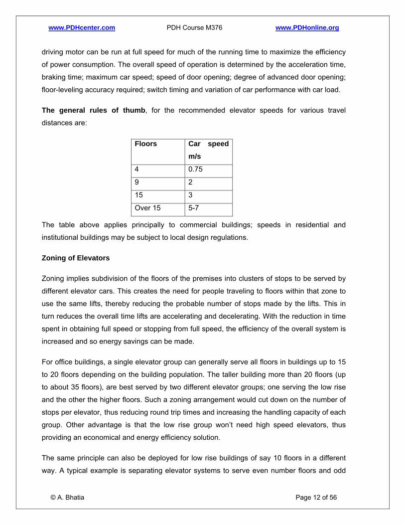
The general rules of thumb, for the recommended elevator speeds for various travel
distances are:
Floors Car speed m/s
4 0.75
9 2
15 3
Over 15 5-7
The table above applies principally to commercial buildings; speeds in residential and
institutional buildings may be subject to local design regulations.
Zoning of Elevators
Zoning implies subdivision of the floors of the premises into clusters of stops to be served by
different elevator cars. This creates the need for people traveling to floors within that zone to
use the same lifts, thereby reducing the probable number of stops made by the lifts. This in
turn reduces the overall time lifts are accelerating and decelerating. With the reduction in time
spent in obtaining full speed or stopping from full speed, the efficiency of the overall system is
increased and so energy savings can be made.
For office buildings, a single elevator group can generally serve all floors in buildings up to 15
to 20 floors depending on the building population. The taller building more than 20 floors (up
to about 35 floors), are best served by two different elevator groups; one serving the low rise
and the other the higher floors. Such a zoning arrangement would cut down on the number of
stops per elevator, thus reducing round trip times and increasing the handling capacity of each
group. Other advantage is that the low rise group won’t need high speed elevators, thus
providing an economical and energy efficiency solution.
© A. Bhatia Page 12 of 56
The same principle can also be deployed for low rise buildings of say 10 floors in a different
way. A typical example is separating elevator systems to serve even number floors and odd

www.PDHcenter.com PDH Course M376 www.PDHonline.org
number floors. If the average waiting time is too long, passengers will call for both lift systems
and travel one floor by stair.
Location of Elevators
The location of elevators shall be such that they are easily accessible and convenient to
circulation routes. When planning the location of elevators, the following principles shall be
observed:
• Elevators should be located so that the building entrances with the heaviest traffic shall
have adequate elevator service. Elevators should be as near to the center of the
building area served as practicable, taking into consideration the distance from the
elevator bank or banks to the most distant functional areas do not exceed a maximum
of 45 meters.
• Congestion at peak travel times is minimized by arranging the lift lobbies in a cul-de-
sac of, say, two lift doors on either side of a walkway, rather than in a line of four doors
along one wall. For passenger cars, three across are preferred, and not more than four
in a row shall be used. Where four or more cars are required within a group, cars shall
be placed in opposite banks, opening into a common lobby.
• As a general guide, the lobby width between two banks of passenger elevators shall
not be less than 3600 mm (~12 ft) and the lobby width between two banks of service
elevators should not be less than 4200 mm (~14’).
• When designing the service core in relation to the floor plate, the designer must ensure
that the elevator lobby should not be used as a common or public thoroughfare at
ground-floor level.
• Where elevators are accessed from corridors, they shall be located on one side of the
corridor only and shall be set back from the line of circulating corridors. Elevator
ingress/egress shall be from a distinct elevator lobby and not directly from a corridor.
© A. Bhatia Page 13 of 56
• Elevator lobbies generate noise and shall be acoustically isolated from areas sensitive
to noise and vibration. Elevators shall not be placed over occupied spaces as this
shall require counter-weight safeties and reinforced pits.

www.PDHcenter.com PDH Course M376 www.PDHonline.org
• Egress stairs shall preferably be located adjacent to elevator lobbies when possible.
• Any decentralized banks and/or clustering of elevators shall be planned to include at
least two cars to maintain an acceptable dispatch interval between cars and to ensure
continuity of service.
• Elevators shall preferably provide positive separation between passenger and freight
/service traffic flows.
• In facilities that utilize interstitial floors and mechanical penthouses, at least one
elevator shall stop on these floors to facilitate equipment maintenance and removal.
Elevator Doors
The doors protect riders from falling into the shaft. The door opening shall be capable of
opening doors at the rate of 0.9 m/s. This is a capability speed, with actual speed being
adjusted to meet the requirements of the specific installation. The closing speed shall be set
per ASME/ANSI A17.1. All power operated doors shall be equipped with an automatic reopen
device for passenger protection.
Door configuration and door opening
The most common configuration is to have two panels that meet in the middle, and slide open
laterally.
• Single-speed bi-parting doors are typically used in the larger capacity ranges and
when dictated by the shaft and platform arrangement. Their operating speed is
generally faster than side-acting doors.
• Two-speed bi-parting doors have the fastest action and are used where a wide
opening is required; they are common on large passenger elevators and service
elevators.
A cascading configuration is sometimes used for wider opening of service elevators where the
doors are tucked behind one another, and while closed, they form cascading layers on one
side.
© A. Bhatia Page 14 of 56
The clear opening (width and height) of an entrance depends on its application.

www.PDHcenter.com PDH Course M376 www.PDHonline.org
• For passenger elevators and handicap access, a minimum door opening width of 1070
mm (3'-6") and height of 2135mm (7’) is recommended.
• Combined passenger/ service elevators typically have doors at least 1220 to 1320 mm
(4'-0" to 4'-4") wide and 2135 to 2440 mm (7'-0" to 8'-0") high.
© A. Bhatia Page 15 of 56

www.PDHcenter.com PDH Course M376 www.PDHonline.org
SECTION – 2 TYPES OF ELEVATORS
The two main types of elevators are hydraulic and traction.
Selection of the best-suited type of elevator considers initial cost of the elevator plus the
building structure needed to house the lift, maintenance costs over the life of the building
and running costs.
TRACTION ELEVATORS
Traction elevators are the most popular form of elevator designs used widely across the world.
These consist of the elevator car and a counterweight held together by steel ropes looped
around the sheave. The sheave is a pulley with grooves around its circumference. The sheave
is driven by the AC or DC motor. The sheave grips the hoist ropes so that when it rotates, the
ropes move, too. This gripping is due to traction.
© A. Bhatia Page 16 of 56
Roping Arrangements
www.PDHcenter.com PDH Course M376 www.PDHonline.org
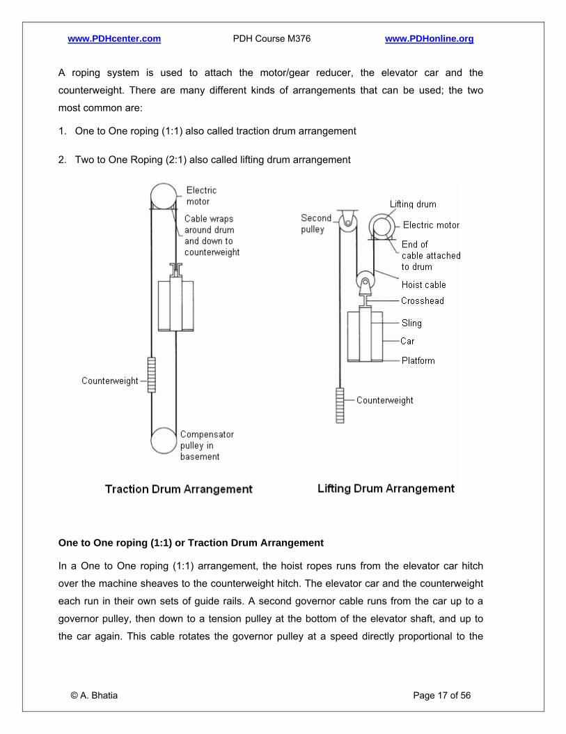
A roping system is used to attach the motor/gear reducer, the elevator car and the
counterweight. There are many different kinds of arrangements that can be used; the two
most common are:
1. One to One roping (1:1) also called traction drum arrangement
2. Two to One Roping (2:1) also called lifting drum arrangement
One to One roping (1:1) or Traction Drum Arrangement
© A. Bhatia Page 17 of 56
In a One to One roping (1:1) arrangement, the hoist ropes runs from the elevator car hitch
over the machine sheaves to the counterweight hitch. The elevator car and the counterweight
each run in their own sets of guide rails. A second governor cable runs from the car up to a
governor pulley, then down to a tension pulley at the bottom of the elevator shaft, and up to
the car again. This cable rotates the governor pulley at a speed directly proportional to the

www.PDHcenter.com PDH Course M376 www.PDHonline.org
speed of the car. In the event of excessive car speed, the governor uses another cable to
activate the emergency brake jaws which grip the guide rails and slow the car to a stop.
Two to One Roping (2:1) or Lifting Drum Arrangement
Arrangement of hoist ropes in which one end of each hoist rope passes from a dead-end hitch
in the overhead, under a car sheave, up over the drive sheave, down around a counterweight
shave and up to another dead-end hitch in the overhead. The car speed is one-half the rope
speed.
Counterweight
When the traction drive is rotated, power is transferred from the traction drive to the elevator
car and counterweight. The counterweight adds accelerating force when the elevator car is
ascending and provides a retarding effort when the car is descending. The counterweight is
normally sized equal to the weight of the car plus approximately half its maximum rated
capacity. It saves energy equivalent to the unbalanced load between the elevator and the
counterweight both when the car is travelling full and empty. The counterweight also ensures
that the elevator cannot fall out of control while the cable is intact.
Hoist Mechanisms
An elevator's function is to convert the electrical power, which runs the motor, into mechanical
power. There are two types of hoisting mechanisms: Geared and Gearless types.
Geared type:
In a geared machine, the motor turns a gear train that rotates the sheave. Geared traction
machines are used for medium-speed applications and have effective speeds from 0.5 m/s
(100 fpm) to 2.0 m/s (400 fpm). The slower speeds are for freight operation, while the higher
speeds are typically used for passenger service in mid-rise buildings of ten stories or less.
© A. Bhatia Page 18 of 56
The geared elevator system most commonly use a worm gear reducer, which is composed of
a worm gear, typically called the worm, and a larger round gear, typically called the worm gear.
These two gears which have rotational axes perpendicular to each other that not only
decreases the rotational speed of the traction pulley, but also change the plane of rotation. By
decreasing the rotation speed, we are also increasing the output torque, therefore, adding the
ability to lift larger objects for a given pulley diameter. A worm gear is chosen over other types
of gearing possibilities because of its compactness, precise speed control, quite operation and

www.PDHcenter.com PDH Course M376 www.PDHonline.org
its ability to withstand higher shock loads. It can also be easily attached to the motor shaft and
has high resistance to reverse shaft rotation.
The efficiency of the gear train is a consideration in the selection of the type of hoisting
machine. Following key facts should be noted, when specifying geared machines:
1. The efficiency of the gear train depends on the lead angle of the gears and the
coefficient of friction of the gear materials. The lead angle is the angle of the worm
tooth or thread with respect to a line perpendicular to the worm axis. As this angle
approaches zero degrees, the reduction ratio increases and the efficiency decreases
due to increased sliding along the gear teeth. For optimum efficiency, the lead angle
should be high usually in the range of 50% to 94%.
2. The efficiency also depends on the operating parameters of the gear train. Usually,
smaller reduction ratios, higher input speeds, and larger gear reducer sizes shall result
in greater efficiencies. However, it does not mean to intent ally over-size the gear train
because the large gear train will operate less efficiently at partial load condition. The
gear reduction ratios typically vary between 12:1 and 30:1.
Geared Traction machines can be driven by AC or DC motors. The machines are normally
located overhead, directly over the hoistway but can be mounted to the side and below; and
when this is done, it is termed as "basement traction" application.
The disadvantage of geared hoisting is that the gear train will loose some energy due to
friction and thus the transmission efficiency of geared elevator is inferior to gearless machine.
Gearless type:
In gearless elevators the motor turns the sheave directly. A brake is mounted between the
motor and drive sheave to hold the elevator stationary at a floor. This brake is usually an
external drum type, which is actuated by spring force.
© A. Bhatia Page 19 of 56
Gearless traction elevators are specified for high-speed applications having effective speeds
varying from 2.5 m/s (400 fpm) to 10.0 m/s (2000 fpm). These are generally used on taller
structures with more than 10 stories. In terms of energy performance, gearless drive has no
gear transmission loss thus have a transmission efficiency of 100%.

www.PDHcenter.com PDH Course M376 www.PDHonline.org
Gearless traction machines use low torque electric motors (generally DC motors) driven by
motor generator (MG) drive or silicon-controlled rectifiers (SCR). Modern gearless traction
machines use variable-voltage; variable frequency (VVVF) drives systems.
ENGINEERING DESIGN
The traction drive depends on the friction, or traction, between the hoisting ropes and the
drum. The hoisting ropes are wound over the drum (possibly several turns are made) and
down to the counter weight, which compensates for the weight of the empty elevator car and
vastly reduces the power needed by the hoisting motor.
The friction between the ropes and the sheave grooves, which are cut on the pulley, initiates
the traction force between the traction drive and the rope. ASME A17.1 mentions that
sufficient traction shall be provided between the rope and groove to safely stop and hold the
car with rated load in the down direction. In most mechanical systems, considerable emphasis
is placed on reducing friction between parts; the reverse is the case in elevators. A lot more
importance is given to utilizing friction for traction-driven machines. In layman’s terms, traction
is the gripping force along the surface. In technical terms, traction is the frictional force.
Traction Calculation
Consider a rope passing over a driving sheave. Let T1 be the tension in the car side, and T2
in the counterweight side.
© A. Bhatia Page 20 of 56
The required traction for the elevator system is expressed as T1 / T2.
www.PDHcenter.com PDH Course M376 www.PDHonline.org
T1 is the addition of all weights (i.e.125% of rated load, car weight and traveling cable weight),
whereas T2 is the tension at counterweight.
The maximum available traction that can be developed is a function of the actual coefficient of
friction between the rope and groove, the shape of groove and angle of contact. Maximum
available traction = efӨ
Where
• e = the base of natural logarithm
• f = coefficient of friction
• Ө = angle of contact
Hence the condition so that the elevator does not lose traction is given by:
T1/T2 * C < efӨ
Where, C is a constant, considering acceleration and deceleration, and is given by:
C = (gn + a) / (gn - a),
Where
• gn = acceleration due to gravity and
• a = rated speed of the elevator.
Obviously, from the above expressions, we can conclude that the maximum traction can be
achieved when the value of fӨ is increased.
Factors Affecting Traction:
© A. Bhatia Page 21 of 56
1. Sheave Diameter: Available traction can be increased by increasing the arc of contact
that the rope subtends with the sheave. The ratio of rope diameter to sheave diameter
plays an important role in traction. As a good engineering practice, the sheave
diameter should be equal to 40 times the rope diameter. The larger the sheave
diameter, the more the contact area between the rope and sheave is achieved. The
www.PDHcenter.com PDH Course M376 www.PDHonline.org
sheave diameter should also be large enough to account for the bending stresses
exerted by the ropes. However, cost is also to be considered while setting the final
diameter. It will also result in a larger machine assembly, which will create problems
during installation.
2. Shape of the Groove: Available traction can be increased by changing the shape of
the groove.
• The V-groove is the most widely used type of groove. These provide the greatest
amount of bearing pressures, hence maximum traction. The angle of the groove is
kept between 32º and 40º. Traction increases with decreasing angle of the groove,
but it also leads to shorter rope life.
• The U-groove is the sheave of choice for optimum life. Its large size, in
combination with its supportive grooves, minimizes abrasion and fatigue. The
groove cradles the rope, resulting in low groove pressures, allowing the wires and
strands to move about freely while the rope is operating. Unfortunately, however,
the U-grooved sheave provides the least amount of traction.
3. Coefficient of Friction: Lastly but not the least, the available traction can be
increased by increasing the actual coefficient of friction of the material.
Note that all the above parameters are dependent on one another. Compromising on any of
the above factors should not change the final traction value. With this background, elevator
system designers need to be very careful in estimating traction and establishing their designs.
CONSTRUCTION OF TRACTION ELEVATORS
© A. Bhatia Page 22 of 56
The elevator car itself is constructed with a steel framework for durability and strength. A set
of steel beams above the car, called the crosshead, span the elevator shaft from side to side
and hold the pulley for the hoist cable. A steel structure, called the sling, extends down the
sides of the car from the crosshead and cradles the floor, or platform. The sides of a
passenger elevator car are usually made from steel sheet and are trimmed on the inside with
decorative paneling. The floor of the car may be tiled or carpeted. Handrails and other interior
trim may be made from stainless steel for appearance and wearability. A suspended ceiling is
usually hung below the actual top of the car and may contain fluorescent lighting above plastic

www.PDHcenter.com PDH Course M376 www.PDHonline.org
diffuser panels. The elevator controls, alarm buttons, and emergency telephone are contained
behind panels in the front of the car, next to the doors.
In a simple installation, the lift shaft of concrete or masonry forms the part of service core.
Guide rails run the length of the shaft to keep the car and counterweight from swaying or
twisting during their travel. Steel guide rollers or guide shoes are attached to the top and
bottom of the sling structure to provide smooth travel along the guide rails. The emergency
brake mechanism consists of two clamping faces which can be driven together by a wedge to
squeeze on the guide rail. The wedge is activated by a screw turned by a drum attached to
the emergency cable.
For further details, refer to Section-3 “Design Criteria of Elevator Systems”.
HYDRAULIC ELEVATORS
Hydraulic elevator systems lift a car using a hydraulic ram, a fluid-driven piston mounted
inside a cylinder. All the weight of the elevator cab is supported on the piston.
The cylinder is connected to a fluid-pumping system (typically, hydraulic systems like this use
oil, but other incompressible fluids would also work). The hydraulic system has three parts:
• A tank (the fluid reservoir)
• A pump, powered by an electric motor
• A valve between the cylinder and the reservoir
The pump forces fluid from the tank into a pipe leading to the cylinder. When the valve is
opened, the pressurized fluid will take the path of least resistance and return to the fluid
reservoir. But when the valve is closed, the pressurized fluid has nowhere to go except into
the cylinder. As the fluid collects in the cylinder, it pushes the piston up, lifting the elevator car.
When the car approaches the correct floor, the control system sends a signal to the electric
motor to gradually shut off the pump. With the pump off, there is no more fluid flowing into the
cylinder, but the fluid that is already in the cylinder cannot escape (it can't flow backward
through the pump, and the valve is still closed). The piston rests on the fluid, and the car stays
where it is.
© A. Bhatia Page 23 of 56
To lower the car, the elevator control system sends a signal to the valve. The valve is
operated electrically by a basic solenoid switch. When the solenoid opens the valve, the fluid

www.PDHcenter.com PDH Course M376 www.PDHonline.org
that has collected in the cylinder can flow out into the fluid reservoir. The weight of the car and
the cargo pushes down on the piston, which drives the fluid into the reservoir. The car
gradually descends. To stop the car at a lower floor, the control system closes the valve again.
The electric motor is redundant during descend.
This system is incredibly simple and highly effective, but it does have some drawbacks.
• Hydraulic elevators consume more energy. Considerable amount of energy is wasted
in heating up the hydraulic fluid when building up the hydraulic pressure; some
installations may even need separate coolers to cool down the fluid to avoid
overheating.
• Hydraulic elevators are usually not provided with a counterweight. Thus the lift motor
has to be large enough to raise the rated load plus the dead weight of the car cage. In
traction lift, the maximum weight to be raised under normal operation is only about half
of its rated load.
• Hydraulic elevators are used in buildings up to 5 floors (14 meters rise) and have rated
speeds of 0.25 m/s (50 fpm) to 0.75 m/s (150 fpm).
© A. Bhatia Page 24 of 56
Basic Types of Hydraulic Elevators

www.PDHcenter.com PDH Course M376 www.PDHonline.org
The hydraulic lifts are of two types. They are
1. Direct-acting hydraulic lift, and
2. Suspended hydraulic lift
Direct acting hydraulic lifts:
The system consists of a ram which slides inside a fixed cylinder. The cylinder has suitable
openings at the bottom for the hydraulic fluid to enter and also suitably designed to allow the
ram to slide up and down. The ram is attached to the top of the car, which acts as a capsule
carrying people or goods. The ram is pushed up by the pressure of hydraulic fluid acting
beneath. Thus the cage moves up to various floors as per the need. The cage is moved in
downward direction by allowing oil to get drained from the cylinder back to the oil reservoir.
Guide rails are required to guide the ram in a vertical plane. Car speed up to 125 feet per
minute (38.1 meters per minute) is attained and maximum travel length is 12 feet (3.6m).
Working: When the pump delivers oil to the bottom of the cylinder, as the valve meant for the
re-circulation remains closed, the oil beneath the bottom of the ram gets pressurized and this
pressurized oil lifts the ram (cage). When the cage has to be lowered, the oil is drained back
to the oil reservoir by keeping the valve open. The time for which the valve is kept open is
decided by the electro-magnetic switch, which gets its signal from the people who use the lift.
Suspended Hydraulic Lifts:
It has a cage (on which people can stand or goods can be placed), which is suspended from a
wire cable, and a jigger consisting of a fixed cylinder, a sliding ram, and a set of two pulley
blocks, which is provided at the foot of the hole of the cage. One pulley block is movable while
the other one is fixed. The sliding ram end is connected to the movable pulley block. The cage
is suspended from the other end of the rope. The raising or lowering of the cage of the lift is
done by the jigger. This arrangement is used to increase the speed of the lift by a 2:1 roping
ratio. Car speed up to 150 feet per minute is attained and maximum travel length is 48 feet
(14m).
© A. Bhatia Page 25 of 56
Working: Water or any hydraulic fluid at a high pressure is admitted into the fixed cylinder of
the jigger. This high pressure hydraulic fluid pushes the sliding ram to move towards left side
as shown in the figure. When the sliding ram moves towards the left side, the distance
between the fixed and movable pulleys increases and thus the cage is lifted up. When the
water or the hydraulic fluid under high pressure inside the cylinder is released, then the
www.PDHcenter.com PDH Course M376 www.PDHonline.org
distance between the two pulleys decreases and thus the cage comes down. Thus the
suspended-type hydraulic lifts are more popular than direct type lifts.
Besides the above basic arrangements, hydraulic elevators can also be installed with more
than one cylinder. On some, the hydraulic piston (plunger) consists of telescoping concentric
tubes, allowing a shallow tube to contain the mechanism below the lowest floor. On others,
the piston requires a deeper hole below the bottom landing, usually with a PVC casing (also
known as a caisson) for protection.
HOIST DRIVES
The motor component of the elevator machine can be either a direct current (DC) motor or an
alternating current (AC) motor. A DC motor had a good starting torque and ease of speed
control. An AC motor is more regularly used because of its ruggedness and simplicity. A motor
is chosen depending on design intent for the elevator. Power required to start the car in
motion is equal to the power to overcome static, or stationary friction, and to accelerate the
mass from rest to full speed. Considerations that must be included in the choice of an
acceptable motor are good speed regulation and good starting torque. In addition, heating of
various electrical components in continuous service should not be excessive.
Various alternatives of hoist motor drives include:
• DC motor drive with motor generator set (DCMG);
• DC motor drive with solid state controller (DCSS);
• AC - 2 speed motor drive;
• AC motor drive with variable voltage controller (ACVV);
• AC motor drive with variable voltage and variable frequency controller (ACVVVF).
DCMG has large energy losses in the motor and generator arrangement, which converts
electrical energy into mechanical energy and finally back to electrical energy again. DCMG
drive is NOT recommended, due to its low inherent efficiency and also because its application
requires it to be kept running when the elevator is idle.
© A. Bhatia Page 26 of 56
The two speed AC motors are also considered energy inefficient. These two speed motors are
usually started up with resistance in the high-speed winding, whilst smooth deceleration is

www.PDHcenter.com PDH Course M376 www.PDHonline.org
obtained by inserting a buffer resistance, either in the low- or high-speed winding during
transition to low speed. The insertion of buffer resistance and choke wastes much energy
during the start up and deceleration.
ACVV and ACVVVF systems are the most energy efficient option. ACVV requires
approximately 70% of the input energy for the same output whereas ACVVVF will only require
50%. If the energy to be fed back into the mains supply is taken into account, a further
reduction of 5% (i.e. 45%) of energy can be achieved for the ACVVVF.
In principle:
o Geared traction machines virtually use variable-voltage; variable frequency (VVVF) AC
drives systems.
o Gearless traction machines use DC or AC motors. DC motors driven by motor
generator (MG) are best suited when there is a possibility of fluctuating line voltage or
the facility contains very sensitive electronic equipment. DC motors driven by silicon-
controlled rectifiers (SCR) use less power and require less maintenance, however,
they are currently more expensive than MG. Now days, virtually all new gearless
traction machines use AC motors driven by the VV or VVVF drive.
o Hydraulic elevator applications typically use AC motors. Direct across-the-line starting
is utilized for motors less than 40 hp and the larger ones use wye-delta starting.
Choice between Hydraulic and Traction Elevators
Hydraulic elevator
Hydraulic elevators operate at slower speeds and serve up to 14 meter of travel. These are
recommended for light usage – low height installations.
Benefits
• Lower ownership costs;
• Quick installation;
© A. Bhatia Page 27 of 56
• Doesn’t need a penthouse or overhead support to house the machinery;
www.PDHcenter.com PDH Course M376 www.PDHonline.org
• Flexibility in the location of the motor room;
• Upon power failure the lift lowers to the ground floor and releases the door.
Drawbacks
• Noisy, slow and poor ride quality;
• High on energy consumption;
• May cause potential environmental damage from leaking hydraulic fluid.
Traction Elevator
Roped traction elevators are much more efficient and safer. Geared traction elevators typically
serve mid-rise buildings with speeds ranging 0.5 to 2.0 m/s and gearless traction elevators
can serve buildings of any height with speeds of 2.5 m/s and higher.
Benefits
• Faster and smoother ride;
• More energy efficient;
• Cost little more to buy.
Speed Comparison
The speed of the elevator shall be within the following ranges and chosen to suit the specific
building requirements as part of the elevator traffic analysis:
• Hydraulic passenger elevators - 0.25 to 0.75 m/s;
• Geared traction passenger elevators - 0.5 to 2.0 m/s;
• Gearless traction passenger elevators - 2.5 m/s and greater.
Lift Comparison
© A. Bhatia Page 28 of 56
The lift of the elevator shall be within the following ranges and chosen to suit the specific
building requirements as part of the elevator traffic analysis:
www.PDHcenter.com PDH Course M376 www.PDHonline.org
• Hydraulic passenger elevators – 15 meter rise up to 5 storeys;
• Geared traction passenger elevators – 30 meter rise up to 10 storeys;
• Gearless traction passenger elevators – above 10 storeys.
Machine Room-less Elevators
All elevators, whether traction or hydraulic, require a machine room to store large electric
motors (or hydraulic pumps) and a controller cabinet. This room is located above the hoistway
(or below, for hydraulic elevators) and may contain machinery for a single or a group of
elevators.
The most significant development in the recent history of elevators has been the introduction
of Motor Room Less (MRL) elevators. Most MRL solutions are based on gearless technology. Traditionally in motor room configurations the sheave, motor and control system
are all housed in a machine room above the elevator shaft but in MRL elevators, the
machinery is installed in the elevator shaft itself.
This was made possible by the development and application of permanent magnet (PM)
system technology in the lift motor that reduced the size of the motor by up to four times. For
example, a 6.5kW motor used in a MRL configuration can perform the same task as a
conventional 16.8kW traction machine. Smaller motors also use less energy. Technical
developments such as increasing the density of the armature winding in the PM and applying
their own proprietary joint-lapped core, further reduced the motor dimensions while improving
its power output. To date the focus from all manufacturers has been on maximising the power
output of the motor while reducing its physical size.
MRL installations are generally cheaper to install, give greater architectural flexibility and
increased lettable space. Presently the speed and number of floors limit their installation -
MRL solutions range up to 30 floors and can reach up to speeds of 2.5m/s.
© A. Bhatia Page 29 of 56
Since the application of MRL technology is relatively new and due to the very fact that each of
the major manufacturers provides propriety products, maintenance needs careful
consideration. Therefore when evaluating the technical aspects the end-user or building
owner should be aware of the potential pitfalls of being trapped into a high cost maintenance
contract and left with no alternative.

www.PDHcenter.com PDH Course M376 www.PDHonline.org
NOTE that the ASME A17.1 code does not specifically address MRL design.
© A. Bhatia Page 30 of 56
www.PDHcenter.com PDH Course M376 www.PDHonline.org
SECTION – 3 ELEVATOR DESIGN CRITERIA
Governing Codes:
Elevators design shall comply with the latest edition of ASME A17.1, “Safety Code for
Elevators and Escalators” with amendments and Uniform Building Code (UBC). Other equally
important standards that govern the design of an elevator include:
1. ADA/ABA - American with Disabilities Act (ADA) Accessibility Guide Lines for Building
and Facilities; Architectural Barriers Act (ABA) Accessibility Guide Lines.
2. ADAAG - American Disabilities Act Accessibility Guide Lines
3. ASCE-7 - America Society of Civil Engineers (Minimum Design Loads for Buildings and
Other Structures)
4. ASME A17.1 - American Society of Mechanical Engineers Safety Code for Elevators and
Escalators.
5. ASME A17.2.1 - Inspector’s Manual for Electric Elevators.
6. ASME A17.2.2 - Inspector’s Manual for Hydraulic Elevators.
7. ASME A17.2.3 - Inspector’s Manual for Escalators.
8. ASME A17.3 - Safety Code for Existing Elevators and Escalators (For designing changes
to existing Elevator/Escalator Systems)
9. NEII - National Elevator Industry, Inc. (1992) –Vertical Transportation Standards
10. NFPA 70 - National Electric Code (NEC)
11. NFPA 80 - Fire Door and Fire Windows
12. NFPA 99 - Health Care Facilities
13. NFPA 101 - Life Safety Code
© A. Bhatia Page 31 of 56
14. UBC - Uniform Building Code

www.PDHcenter.com PDH Course M376 www.PDHonline.org
15. UFAS - Uniform Federal Accessibility Standards
International Elevator Standards:
• Australia - AS1735
• Canada - CAN/CSA B44
• Europe - EN 81 series [EN 81-1 (electrical elevators), EN 81-2 (hydraulic elevators),
EN 81-28, EN 81-70, EN 12015, EN 12016, EN 13015, etc.]
The various codes may have conflicting requirements or have many potential pitfalls. But by
understanding how these fit together and what purpose they serve, you can have a successful
project. Always verify all conditions and requirements with the state and the AHJ where the
installation is taking place. ASME/ANSI A17.1, A17.2, A17.3, and A17.5 usually take
precedence over all other codes in US unless specifically advised.
ARCHITECTURAL DESIGN CRITERIA
Elevator runs in a hoistway built within the “Service core”. Service core is one of the most
important aspects of high rise buildings - the design of this is predominantly governed by the
fundamental requirements of meeting fire-egress regulations, achieving basic efficiency in
human movement, and creating an efficient internal layout. Typically the service core provides
the principal structural element for both the gravity load-resisting system and lateral load-
resisting system, with the latter becoming increasingly important as the height of the building
increases. The core provides the stiffness to restrict deflections and accelerations to
acceptable levels at the top of the building. The cost of a core for a typical high rise building is
estimated to be around 35 to 40 percent of the total structural cost, or 4 to 5 percent of the
total development cost.
Elevator Shafts within the Service Core:
Once the location of the service core is determined, the exact size of the core (internal shaft
dimensions, wall thickness, etc.) needs to be established.
It is next necessary to define design criteria for the services shaft and the elevator system.
Early liaison with the fire officer is important in establishing life-safety requirements.
© A. Bhatia Page 32 of 56
The fire department may require fire compartmentation between the elevator lobby and
elevator shafts. A separate fire-fighting elevator — capable of moving firefighters around a
burning building when all other lifts have returned to their neutral position — is often required.

www.PDHcenter.com PDH Course M376 www.PDHonline.org
In organizing the configuration of elevator banks in the service core, it is necessary to ensure
that a bank of two, three, or four elevators in line shares a common fire-protected shaft without
a dividing structure, so avoiding a single enclosed elevator shaft. If single enclosed elevator
wells are necessary for structural reasons, the designer must ensure that air relief slots
(ideally, full-height vertical slots) to allow adequate air relief.
Note - The core configuration is normally finalized at an early stage of design development
because of its implications for the functional layout of the building. Traditionally, the
configuration is greatly influenced by the architect. The design optimization process is
subsequently carried out by the structural and building services engineers. A large bank of
elevators is the main element in a service core design and all other elements are designed
around it.
STRUCTURAL DESIGN CRITERIA
The elevator cars are built at the elevator manufacturer's plant using standard metal cutting,
welding, and forming techniques. The rest of the elevator is assembled on the building site.
Elevator shafts are sized according to car shapes and sizes and door sizes, with due
consideration given to space requirements for guide rails and brackets, counterweight
systems, running clearances, and ancillary equipment. Sufficient air space should always be
provided around cars and elevator counterweights to minimize buffeting and airborne noise
during operation.
The building design integrates the elevator shaft from the beginning, and the shaft grows as
the building is erected. The walls of the shaft are poured concrete, and the shaft straightness
and other dimensions are carefully monitored as each floor goes up.
Guide rails, switch ramps, service ladders, and similar support equipment are bolted into the
shaft after the shaft walls are complete, but before the shaft is roofed. While the shaft is still
open at the top, a crane raises the counterweight to the top of the building and lowers it into
the shaft along its rails. The crane then lifts the elevator car and inserts it partly into the shaft.
The guide wheels connect the car to the guide rails, and the car is carefully lowered to the
bottom of the shaft.
© A. Bhatia Page 33 of 56
The shaft is then roofed over, leaving a machine room above the shaft. The hoist motor,
governor, controller, and other equipment are mounted in this room, with the motor located

www.PDHcenter.com PDH Course M376 www.PDHonline.org
directly over the elevator car pulley. The elevator and governor cables are strung and
attached, the electrical connections completed, and the controller programmed.
The structural design of elevator is goverened by ASME 17.1 and ASCE-7, in addition to local
codes and standards. The following key points should be noted:
Hoistway:
1. Construction of the hoistway enclosure should be fire resistant, generally 2-hour fire
rating and in accordance with the applicable building regulations. All penetrations for
services through the walls of the service core need to be designed to maintain fire
integrity for the prescribed period of time.
2. All elements that are part of the elevator system, particularly guide rail tie brackets,
intermediate spreader brackets and framing, as well as supports and attachments for
driving machinery shall be spaced dictated by seismic conditions, design particulars
and codes. It is important to avoid the use of tile or brick hoistway walls.
3. Beveling of the top surface of projections and setbacks in the hoistway enclosures
shall be in accordance with Rule 100.6 of ASME 17.1.
4. A vertical surface is needed for attachment of sill angles to the floor slab on each
landing where an entrance is required; or otherwise consider a notch on the top edge
of each floor slab on the entire width of the hoistway to accommodate landing sills.
5. Where the hoistway enclosure is concrete construction, provide rough openings for
hoistway entrances and grouting following installation. Where drywall hoistway
construction is utilized, erect walls around previously installed hoistway entrances.
Deviation from plumb for the hoistway enclosure should not exceed ±25 mm (1 inch)
per 20 stories of height.
6. Provide rough openings for control/signal fixture recessed mounting boxes and
grouting thereof as required to maintain fire resistive characteristics of the hoistway
enclosure.
© A. Bhatia Page 34 of 56
7. On hydraulic elevators, sprinkler protection is required at the top of the hoistway when
the hydraulic cylinder or supply piping extends above the second finished floor

www.PDHcenter.com PDH Course M376 www.PDHonline.org
elevation. On hydraulic elevators, the hydraulic oil lines shall remain in or under
conditioned space within the building footprint. Consider straight pipe run in PVC pipe
sleeves for oil spill containment of all buried hydraulic lines between machine room
and the hoistway.
Don’ts
• Avoid locating building expansion joints between the elevator hoistway and elevator
room.
• The elevator code does NOT allow anything to be installed in the hoistway not related
to the elevator operation. Pipes, ducts and conduit not related to the elevator system
are NOT allowed to penetrate the hoistway.
Elevator Pit:
1. Elevator pit shall meet the ASME A17.1 Code requirements. Elevator pit shall be
waterproofed as required by site conditions and codes.
2. Pit shall have a concrete floor reinforced as necessary to withstand vertical forces of
elevator car or counterweight buffer impact, application of car or counterweight
safeties to guide rails, or operation of the hydraulic jack.
3. Pit shall have a sump in a front corner with a removable steel subway-type grating
installed level with the pit floor. The sump shall be constructed to minimum dimensions
of 610 mm (2 ft) cubed.
4. Where the difference in depth between adjacent pits is more than 610 mm (2 ft)
provide a means of separation extending from the pit floor to a height of not less than
1830 mm (6 ft). Perforated materials used for the separation of pits shall reject
passage of a 50 mm (2.0 inch) diameter ball.
© A. Bhatia Page 35 of 56
5. Where pit access is greater than 915 mm (3 ft) in depth and is via the lowest hoistway
entrance, provide a permanently installed pit access ladder, accessible from the
hoistway entrance, extending from the pit floor to no less that 1065 mm (3'-6") above
the bottom landing sill.
www.PDHcenter.com PDH Course M376 www.PDHonline.org
6. Where conditions allow and pit depth is 2440 mm (8 ft) or greater, provide a walk-in
access door with clear opening dimensions of not less than 760 mm (2'-6") wide by
1830 mm (6 ft) high. This door shall be equipped with a self latching lock mechanism
(key-entry only), automatic closing device, and signage to prohibit unauthorized entry.
7. A buffer access ladder shall be provided whenever the buffer oil level gauge is located
more than 1525 mm (5 ft) above the pit floor. A buffer inspection platform and access
ladder shall be provided whenever that dimension is greater than 2135 mm (7 ft).
8. On hydraulic elevators, sprinkler protection is required in the pit of each elevator.
Don’ts
• An elevator pit floor drain is NOT acceptable by codes. Elevator pit must have floor
sump pit and pump sized for a minimum 20 gallons per minute. Permanent drainage
installations require consideration of environmental regulations governing the
discharge. Pump to sanitary sewer through a 2” (50 mm) air gap or directly through an
oil/water separator to storm sewer, or to grade outside the building line is sometimes
permissible in accordance with discharge permits, regulations, and statutes.
Machine Room:
1. Elevator machine rooms shall be large enough for the elevator equipment, including
space for controllers. Machine rooms and secondary machinery spaces shall provide
required clearances around the equipment and it should be possible to remove major
equipment components of each elevator for repair without dismantling components of
an adjacent elevator. Minimum headroom shall be 2300 mm (7'6").
2. Elevator machine rooms shall be of fire resistant construction (generally 2 hour)
equivalent to hoistway construction. Machine room door (exiting to the interior of the
building) shall be “B” Label, fire rated 1½ hour with automatic closure, latching door
hardware, panic hardware exit device from interior of room, and key operated
hardware from outside of room only.
© A. Bhatia Page 36 of 56
3. Elevator machine rooms access doors shall conform to ASME A17.1 Code. Access
doors to elevator machine rooms and secondary machinery spaces shall be of the self-

www.PDHcenter.com PDH Course M376 www.PDHonline.org
closing and self locking type. They should be provided with spring-type locks arranged
to permit the doors to be opened from the inside without a key.
4. Where machine room and/or secondary machinery space floor levels is above or
below the point of access, provide fixed, permanent, noncombustible stairs with a
maximum angle of 60 from horizontal.
5. Provide support for machine beams and grouting thereof after installation. Whenever
possible, place machine beams on top of building steel in such manner as to be flush
with the machine room floor.
6. Provide an overhead hoisting beam in the machine room, installed directly above the
hoistway, sized in accordance with the requirements of the elevator manufacturer.
7. All openings in the floor for passage of hoist ropes, etc. shall have a 50 mm (2 inch)
high concrete curb or 50 mm (2 inch) high metal sleeves.
Don’ts
• Machine room door shall NOT contain ventilation louvers or undercuts in excess of
NFPA 80, Section 1- 11.4 requirements.
• Exposed spray on fireproofing shall NOT be used in elevator machine room.
• Skylights shall NOT be installed in elevator machine rooms.
• Drains or sumps shall NOT be provided in elevator machine rooms. The room should
be made reasonably watertight. Curbs may be provided at the doors to prevent the
ingress of water. Overhead fluid piping shall not be permitted in the machine room,
except for sprinkler piping, if required. Pipes, ducts and conduit not related to the
elevator system are not allowed to penetrate the machine room. Refer ASME A17.1
(Rule 101.2, Equipment in Machine Rooms).
Clearances:
© A. Bhatia Page 37 of 56
The design of elevator systems is dependent on providing proper clearances around
equipment and at the top and bottom of the hoistway. Most clearances are dictated by the
Elevator Code, ASME A17.1. Other clearances have been established by elevator
www.PDHcenter.com PDH Course M376 www.PDHonline.org
manufacturers based on their equipment. Care shall be taken to consider several elevator
manufacturers' requirements and design for the "worst case" to allow maximum opportunity for
competitive bidding. The following represents some of the elevator code-related clearances
which shall be considered in design:
1. Pit depth is based on the thickness of the platform, the safety plank, the run-by (set by
code), and the buffer stroke (set by code based on speed), plus a minimum bottom-of-
car clearance when the car is on compressed buffer.
2. Top terminal over-travel is based on the cab height (determined by designer), shackle
clearance (determined by elevator industry), crosshead thickness (determined by
elevator industry), and run-by (determined by code).
3. Clearances for items such as counterweight space, rail space, machine and controller
size, machine room height, top & side emergency exits and area of safe refuge on top
of cab shall be based on the manufacturers' recommendations and are also related to
control and operation.
ELECTRICAL DESIGN CRITERIA
Machine Room Supply:
1. Each elevator shall be provided with a separate three phase supply through a lockable
safety disconnect device, located adjacent to the door of the equipment room. This
device must be either a fused disconnect or a circuit breaker because ANSI/ASME
A17.1 requires to install an additional over-current protection device (OCPD) in the
elevator equipment room.
2. Each elevator machine room shall be provided with a minimum of one ground type
duplex receptacle outlet per elevator, and one receptacle for the master intercom
panel; NEC 620-23 and NEC 620-85. Machine room shall be equipped with a 120
volt/20 ampere minimum, ground fault circuit interrupter (GFI) – protected duplex
receptacle capable of locking in the off position. The circuit breaker panel shall contain:
• A separate circuit to each elevator for fan, lights and alarm;
© A. Bhatia Page 38 of 56
• A separate circuit for the machine room lights;

www.PDHcenter.com PDH Course M376 www.PDHonline.org
• A separate circuit for the machine room receptacles;
• A separate circuit for the hoistway lights;
• A separate circuit for hoistway receptacles;
• Each hydraulic elevator shall be provided with a separate circuit for the
scavenger pump in the pit.
3. Provide a separate insulated feeder and grounding conductor from the electrical
source to the elevator controller. The conduit alone can NOT act as the grounding
means.
4. All conductors and optical fibers located in the machine room shall be in conduit.
5. Where a feeder powers more than one elevator, the OCPDs must be series-designed
so a fault at one of the elevators shall be cleared by only the OCPD serving it. The
feeder OCPD needs to remain closed so the remaining elevators have power and
continue to function.
6. Designer shall consider types of hoist drives specified, i.e., Silicon Controlled Rectifier
(SCR), Variable Frequency Drive (VFD), motor generator, etc., and size service and
wire for the worse case. Consider individual isolation transformers and individual
choke reactors for each hoist motor and harmonic distortion filter units when SCR or
Variable Voltage Variable Frequency (VVVF) AC controllers are utilized.
7. The elevator supply shall be dedicated main feeder utilizing the shortest practical run
and continuous ground conductor. The supply should terminate at the respective
elevator controller.
Elevator Pit Supply:
1. Sump pump shall be provided with a twist lock simplex receptacle with matching plug,
without GFI protection. Provide pilot lamp to verify circuit is energized. NEC 620-85.
© A. Bhatia Page 39 of 56
2. A separate branch circuit shall be provided for the hoistway pit lighting and at least one
duplex receptacle in the pit. All duplex receptacles in the pit shall be GFI. NEC-24,
NEC 620-85.

www.PDHcenter.com PDH Course M376 www.PDHonline.org
3. Locate permanent vapor tight light with wire guard at a centerline height of 2440 mm (8
ft) above the pit floor and capable of producing at least 54 lux (5 footcandles) of
illumination at floor level, and a light switch inside the pit, accessible from the pit
access door and adjacent to the pit access ladder, if used.
Don’ts
• When sprinklers are provided in the elevator pit, activation of the sprinkler is not
required to initiate shutdown of elevator power.
Elevator Hoistway:
1. Only electric wiring, raceways, and cables used directly in connection with the elevator
shall be permitted inside the hoistway (Refer NEC 620-37).
2. All conductors and optical fibers located in the hoistway, except for the traveling cable,
shall be in conduit.
3. When a replacement or upgraded elevator is installed in an existing hoistway, any
utilities and services (conduit, control wiring, etc.) not associated with the elevator
system shall be removed from the hoistway, as required by code.
4. Light switch shall be located on wall inside the hoistway adjacent to the top of the pit
ladder in accordance with NEC 620-24.
5. When sprinkler protection is required at the top of the hydraulic elevator hoistway,
actuation of that sprinkler(s) shall initiate operation of the elevator power shunt trip
breaker(s). Provide smoke detection at the top of the hoistway whenever sprinklers are
installed in the hoistway.
Emergency Power:
Elevator cab lights require emergency back-up power. If the building has emergency power
available, use it to supply the cab lights. Otherwise, specify that the elevator supplier provide a
battery back-up unit to power the lights in the event of an outage.
© A. Bhatia Page 40 of 56
The new ADAAG guidelines require that emergency power be available to elevators that have
four or more stories of travel above or below the accessible floor. If emergency power is used:

www.PDHcenter.com PDH Course M376 www.PDHonline.org
1. The disconnecting means required by NEC 620-51 must disconnect the elevator from
normal power and from emergency power.
2. If more than one elevator is provided, determine (with activity input) how many
elevators are to operate on emergency power.
3. Design the emergency power to be able to operate selected elevator(s) at rated loads
and rated speeds.
4. System design must accommodate automatic sequential operation in order to bring all
elevators to the designated floor level, as required by ASME A17.1 (Rule 211.3b
Smoke Detectors) and provide selected elevator(s) with emergency power operations.
5. Provide manual override switch in main elevator lobby area(s) to override the
automatic emergency power selection.
6. Provide emergency power for machine room cooling/ventilation equipment and
hoistway
7. Ventilating equipment, if the elevator is on emergency power circuit. Provide an extra
set of contacts on transfer switch (when emergency power is provided) and two-
conductor 120-volt ac circuit in conduit from these contacts to junction box in machine
room.
Ventilation and Air conditioning
1. Modern electronic elevator controls can be sensitive to temperature shifts. Air-
conditioning is required in most conditions; gravity ventilation is not acceptable. Refer
ASME A. 17.1 (Rule 101.5, Lighting and Ventilation of Machine Rooms and Machinery
Spaces).
2. Heating, ventilation and cooling shall be provided in the machine room as necessary to
maintain temperature within a range of 10-32°C (50-90°F) and relative humidity
sufficiently low to prevent condensation in sensitive equipment. The most cost-
effective HVAC design that shall accommodate these requirements should be selected.
© A. Bhatia Page 41 of 56
3. Cooling is typically provided through the use of return air from adjacent air conditioned
spaces as exhaust for the machine room, or via dedicated cooling units. Designs shall

www.PDHcenter.com PDH Course M376 www.PDHonline.org
provide an ambient environment which maintains the temperature and humidity within
the tolerances of the elevator equipment specified.
4. Where elevator control systems or equipment shall remain energized during the
building's unoccupied hours, means should be provided to maintain machine room
temperature and humidity without depending on main HVAC systems that could
otherwise be shut down or set back.
5. If the elevator equipment has an emergency power supply, the machine room HVAC
should also be on emergency power circuit.
6. The National Building Codes require that all elevator hoistways be vented to prevent
accumulation of hot gases and smoke inside the hoistway. This requirement includes
non-personnel elevators if equipped with the means for top of car operation by service
personnel. The required vent shall be controlled by a motorized louver that is powered
closed. This louver shall open upon loss of electrical power or by a signal from either
a smoke detector or activation of the Fire Emergency Service in any other manner.
7. Where hydraulic elevators are installed in cold climates and subject to intermittent use,
provide means to maintain the oil temperature within acceptable operating limits.
Communication:
The Americans with Disabilities Act Accessibility Guidelines for Buildings and Facilities
(ADAAG) require the cab to have a special phone accessible by individuals with disabilities. In
the event of a breakdown, that phone must automatically call a location staffed 24 hours a day.
High-rise buildings pose additional concerns. The Uniform Building Code requires two-way
communications between the central command center and the elevators, each elevator lobby,
emergency power rooms, and by entries into enclosed stairways (Section 403.5.3). Fireman
telephone jacks and telephone cabling are typically sufficient for each of these locations.
Firefighters can then use portable telephone handsets in combination with the jacks and
cabling.
FIRE PROTECTION DESIGN CRITERIA
© A. Bhatia Page 42 of 56
The vertical transportation of people within a high rise building also depends on local fire
regulations. The fire department may require fire compartmentation between the elevator

www.PDHcenter.com PDH Course M376 www.PDHonline.org
lobby and elevator shafts. A separate fire-fighting elevator — capable of moving firefighters
around a burning building when all other lifts have returned to their neutral position — is often
required.
Fire Alarm & Detection:
Dual-contact smoke detectors or addressable fire alarm system smoke detectors and control
modules shall be provided at:
• All elevator lobbies;
• Top of the hoistway (only if sprinklers are provided at the top of the hoistway);
• Elevator machine room.
Smoke detectors, which are required in all elevator lobbies and elevator equipment rooms,
must be connected to the elevator controllers directly by means of auxiliary contacts and
wiring, or indirectly by means of output signals from the fire alarm control panel. If a smoke
detector goes into alarm, it signals the elevator to go into “Fire Recall Function,” at which point
the controller directs the elevator cab to travel to its pre-programmed designated landing,
open its doors, and remain stopped there until the alarm clears;(as required by ASME A17.1
(Rule 211.3b, Smoke Detectors).
If the smoke detector at the designated landing goes into alarm, the elevator shall stop at a
predetermined alternate floor, which is usually the floor above the designated floor. However,
this can vary depending on building conditions and exterior grade. Therefore, there shall be
two signals to the elevator control panel related to smoke detectors: one from the “designated
floor” smoke detector and another combined signal from the smoke detectors at the other
lobby landings and in the equipment room.
Regardless of the number of elevators, only one smoke detector is required at each floor
lobby, but it must be located within 21 feet of every elevator door. Be sure to provide a
horn/strobe alarm in large equipment rooms because they can be noisy, isolated places.
© A. Bhatia Page 43 of 56
If a hydraulic elevator loses power because a heat detector goes off — or for any other reason
— it could trap occupants for an unpleasant amount of time. To avoid this situation, designers
can specify elevator controls with a safety feature commonly called a rescuvator. Upon loss

www.PDHcenter.com PDH Course M376 www.PDHonline.org
of power, the rescuvator controls the cab, lowers it to the designated floor, and opens its
doors. If you specify a rescuvator, you must also specify a disconnect switch with an auxiliary
contact that opens when the disconnect arm moves to the open position, but stays closed
when the OCPD trips. This switch shall ensure that the elevator won't descend into the
elevator pit and allow maintenance people to work safely in the area beneath the cab.
Detectors shall be connected to building fire alarm system in accordance with NFPA 72. Only
elevator smoke detectors shall initiate automatic emergency recall.
Fire Water Spray Protection:
In buildings required to be fully sprinklered, automatic sprinklers shall be provided in elevator
hoistways and machine rooms as required by NFPA 13. In accordance with NFPA 13,
Sprinklers are required:
• Hydraulic Elevators Hoistways – YES
• Traction Elevators Hoistways – NO
• Traction Elevators Machine Room – YES
• Hydraulic Elevators Pit – YES
Key Features
Waterflow Switches and Valves:
1. A waterflow switch, outside stem and yoke (O.S& Y) control valve and check valve
assembly shall be provided for the elevator sprinklers.
2. The control valves shall be located outside of and adjacent to the protected elevator
machine room or hoistway.
3. A separate waterflow switch, O.S& Y valve and check valve assembly shall be
provided for each floor level where elevator machine room or hoistway sprinklers are
located.
© A. Bhatia Page 44 of 56
4. Control valves shall be readily accessible to qualified personnel, but should NOT be
readily accessible to the general public.
www.PDHcenter.com PDH Course M376 www.PDHonline.org
5. An inspector's test connection with outside discharge shall be provided for each
waterflow switch. Sprinkler heads shall be standard heads with intermediate
temperature classification.
Heat Detectors:
• A fixed temperature heat detector, rated at 57-60°C (135-140°F), shall be provided
within 610 mm (2 ft) laterally of each sprinkler head located in the elevator machine
room. Activation of a heat detector shall cause shunt trip breaker(s) to disconnect the
main line power to the affected elevator. The actuation of heat detector(s) shall cause
a “supervisory alarm” on the building’s fire protective signaling system, if provided. No
heat detectors are required in the traction elevator hoist way.
Automatic Power Shutdown
To safeguard the passengers and electrical equipment, ASME A17.12.8.2.3.2 requires the
power source to the elevator control panel to shut down prior to the discharge of water from a
sprinkler head. The shut down shall be activated by operation of a shunt-trip breaker in the
main line power supply. Depending on your local codes, this can be achieved by installing
heat or smoke detectors within 24 inches of the sprinkler heads. Actuation of such heat
detector or sprinkler head shall cause the following sequence of operation for the affected
elevators:
• Elevators which are in motion shall proceed to the nearest available landing away from
the fire floors. Upon arrival and stopping at landing, power operated doors shall open
and remain open.
• Elevators which are standing at a landing with open doors shall remain open at that
floor. If power-operated doors are closed, the system shall cause the doors to open.
• Shutdown shall occur only after the elevators are stopped at a landing, and power-
operated doors are opened.
© A. Bhatia Page 45 of 56
• Automatic shutdown shall override Phase I emergency recall operation, but shall not
override Phase II emergency in-car operation per ASME A17.1, if Phase II operation is
in effect.

www.PDHcenter.com PDH Course M376 www.PDHonline.org
• Actuation of the pit sprinkler shall NOT disconnect power to the elevator.
Fireman’s Lift:
Firefighting or fireman’s lift is an essential provision in all the high-rise buildings. The important
requirements for design and installation of such a lift are:
1. Break-glass key switch (at G/F to control the lift);
2. Minimum duty load, say 630 kg (for firefighting equipment);
3. Minimum internal dimensions (m), 1.1(W) x 1.4(D) x 2.0(H);
4. An emergency hatch in the car roof;
5. Manufactured from non-combustible material;
6. A two-way intercom;
7. 1 hour fire-resisting doors of 0.8 m (W) x 2 m (H);
8. A maximum of 60 sec to run full building height;
9. Dual power supplies (normal + emergency).
ELEVATOR CONTROLLERS
Electromechanical switching is the oldest controller technology for elevator drive systems.
Modern installations use microprocessor and relay logic controllers.
1. Microprocessor: Computer logic control is the standard for both electric traction and
hydraulic elevators.
2. Relay logic: Mechanical electro-magnetic controller relays control the operation of the
elevator.
© A. Bhatia Page 46 of 56
Microprocessors are typical in most installations. However, if you have a base that is located
in a remote location or subject to erratic building power supply, a relay logic controller may be
the best choice.

www.PDHcenter.com PDH Course M376 www.PDHonline.org
ENVIRONMENTAL FACTORS:
The design shall consider the need to prevent or minimize environmental impacts, such as
ground oil contamination and noise pollution.
1. Noise levels above 60 DBA should not be accepted outside of elevator machine rooms
or inside of elevator cabs.
2. Oil leaks must be contained. In-ground pistons for hydraulic elevators should be
protected by a sealed, schedule 80 PVC watertight cylinder with a water-stop ring
embedded in the pit floor.
SECURITY CONSIDERATIONS:
These will be developed in conjunction with the user. In general, it is better to provide security
access control independent of the elevator system. Security in an elevator system, if
necessary, can be provided by conventional key lockouts or by card keys.
1. Conventional keys are least desirable because they are easily duplicated and usually
require considerable time to insert and actuate, thereby slowing the operation of the
elevator.
2. Card keys shall be used. These should be applied in conjunction with a security
computer so that the elevator system only passes the signal through and does not
have to process it.
© A. Bhatia Page 47 of 56
www.PDHcenter.com PDH Course M376 www.PDHonline.org
SECTION – 4 ELEVATOR CONTROL AND SAFETY FEATURES
The modern elevator control systems include a logic controller that takes the user’s input and
translates it into meaningful actions. The logic controller's central processing unit (CPU) must
be given at least three critical pieces of information, namely:
• Where people want to go?
• Where each floor is?
• Where the elevator car is?
The first input “where people want to go” comes directly from the users and the elevator
controls must interface with user’s requests. In its simplest form when the users desire to ride
the elevator they press a button located in the elevator lobby. The lobby is defined as the area
of the building, adjacent to the elevator, on a given floor. The user presses the either of two
buttons, up or down, correlating to the direction they want to move. The elevator logic
controller receives the signal and responds by traveling via the path of predetermined travel
routes or cycles. An elevator that is initially idle will dispatch immediately to the floor of the
user request. The elevator will stop only for other requests for moving in its current direction of
travel. Once all requests have been serviced in one direction of a cycle, the elevator will
reverse and begin responding to requests in the same manner as before. An elevator that is
idle for several minutes will return to the ground, or bottom, floor.
The second input "where each floor is" can often be determined by the addition of holes
located on a long vertical tape inside the elevator shaft. The elevator car is equipped with a
light or magnetic sensor that reads the number of and which holes are being passed by the
elevator car as it ascends and descends. The elevator controller is equipped with a means of
varying the motor’s speed based on a set of feedback signals that indicate the car’s position in
the shaftway. As the car approaches its destination, a sensor near the landing, signals the
controls to stop the car at floor level. Additional shaftway limit sensors are installed to monitor
over travel & under travel.
© A. Bhatia Page 48 of 56
The third input "where the elevator car is” related to the elevator scheduling operations. When
a user presses the ‘Up’ or ‘Down’ button outside the elevator car, the elevator should begin
moving towards them. Logic controllers must have some way to determine in what order riders
should be picked up and dropped off. Many elevator systems will move in one direction (e.g.,
upward) and only pick up riders that are also signaling to go in that direction (e.g., upward).

www.PDHcenter.com PDH Course M376 www.PDHonline.org
When the final floor that has been requested in that direction (e.g., upward) is reached the
elevator will turn around and pick up all riders signaling the opposite direction (e.g.,
downward). Of course, the elevator car also stops at all floors for which riders, already inside
the car, have input a requested. A more sophisticated system, often used in hotels and other
large buildings with a lot of foot traffic, involves the traffic patterns that reoccur. These
systems have logic controllers that are programmed with information about the demand on
each floor with respect to the time of day and they route the elevator cars accordingly so as to
minimize the wait for all riders. When there are multiple elevator cars, the logic controller
bases the movement on each car on that of the others. Often, the elevator car is equipped
with a load sensor so that if the elevator is full to capacity it sends a signal to the control
system and the logic controller signals the car not to pick up any more passengers until the
load is lowered.
SIMPLEX CONTROLS
Many different types of systems may be applied to control elevators. All new elevators will be
microprocessor-controlled. A single-car system is referred to as "simplex", a two-car system
as "duplex", and a system having three or more cars as "group supervisory operation". There
are a number of sub-systems such as independent service; attendant service; inspect service;
fire service etc. that can be added to the main control system.
Independent service:
Independent service allows the elevator to be run from within the car without responding to
hall calls. (In a bank of elevators, traffic would be rerouted to the other elevators, while in a
single elevator; the hall buttons will be disabled). The elevator will remain parked on a floor
with its doors open until a floor is selected and the door close button is held until the elevator
starts to travel. Independent service is useful when transporting large goods or moving groups
of people between certain floors. This service shall be included on all cars.
Attendant service:
© A. Bhatia Page 49 of 56
Attendant service is activated from a key switch in the car. It allows an attendant in the car to
control the opening and closing of the doors, the direction of travel, and whether to stop or
bypass hall calls. When there is more than one car in a group, a car on attendant service is
usually called by a separate, inconspicuous corridor push-button riser. Attendant service
operation is frequently used for combined passenger/service applications.
www.PDHcenter.com PDH Course M376 www.PDHonline.org
Inspect service:
When an elevator is placed in inspect mode, the elevator will no longer respond to calls and
comes immediately to a halt. In theory, this mode could be used as a way to stop the car in
mid flight if one did not have a stop switch key. The elevator car will continue to remain idle
until given a command from a corresponding access key switch. Key switches for access are
usually located at the bottom floor and top floor. This enables the Elevator Mechanic to gain
access to the pit of the elevator or the car top. Since this key allows entry into the hoist way of
the elevator, this key is not given out and is restricted only for use by qualified elevator
technicians.
Fire service:
Fire service is usually split up into two modes; ‘phase-I’ and ‘phase-II’.
Phase-I mode is activated by smoke sensor or heat sensor in the building. Once the fire alarm
is activated, the elevator will wait an amount of time, and then proceed to go into nudging
mode to tell everyone the elevator is leaving the floor. Once the elevator has left the floor,
depending on where the alarm was set off, the elevator will go to the Fire Recall Floor.
However, if the alarm is activated on the fire recall floor, the elevator will have an alternate
floor to recall to. When the elevator is recalled, it proceeds to the recall floor and stops with its
doors open. The elevator will no longer respond to calls or move in direction.
Phase-II mode can only be activated by a key switch located inside the elevator, on the
centralized control panel (CCP). This mode is created for firefighters so that they may rescue
people from a burning building. The phase-II key switch located on the CCP has three
positions: off, on, and hold. By turning phase-II on, you enable the car to move in direction.
However, like independent service mode, the car will not respond to a car call unless you
manually push and hold the door close button. Once the elevator gets to the desired floor, it
will not open its doors unless you hold door open. This is in case the floor is burning and the
firefighter can feel the heat and knows not to open the door. You must hold door open until the
door is completely opened. For any reason the firefighter wishes to leave the elevator, they
will use the hold position on the key switch to make sure the elevator remains at that floor. At
anytime the firefighter wishes to return to the recall floor, they simply turn the key off and close
the doors.
© A. Bhatia Page 50 of 56
Group Supervisory Control System
www.PDHcenter.com PDH Course M376 www.PDHonline.org
Modern commercial buildings commonly have multiple elevators with a unified control system.
The objective here is to minimize the average time any passenger spends from the time the
elevator call button is pushed to the arrival of the first available elevator. Different systems use
different levels of sophistication. The simplest systems use a single up and down button on
each floor regardless of the number of elevators. When a passenger calls for an elevator, the
controller sends the nearest elevator that is traveling in the desired direction. The approach of
an elevator car is signaled by an illuminated arrow above the elevators doors pointing up or
down.
In more sophisticated systems, the controller monitors the elevator call system for a set, or
bank, of elevators operating side by side. The operation zone of these elevators is divided into
sectors, with each sector being made up of adjacent floors. When a car has answered a call
and completed the designated run, it becomes available to answer another call. At this point,
depending on the controller's programming, the car may be returned to a designated "home"
floor, or may be sent to the sector furthest from other operating or available cars to cover that
sector. When a call is received, the controller automatically compares the location of all the
cars in the bank and sends the nearest one.
Controllers can also be programmed to respond differently at different times of the day. For
example, the elevator controller in a busy office building will receive a preponderance of calls
from the ground floor in the morning, when workers are arriving and need to go to their
workplaces on the upper floors. In that case, the controller will be programmed to send all
unassigned cars to the ground floor, rather than have them return to a home floor in their
sector. Later in the day, a different set of instructions can be used to send unassigned
elevators to different sectors, since passengers leaving the building will be much more evenly
distributed among the floors than in the morning.
ELEVATOR SAFETY
© A. Bhatia Page 51 of 56
A major attribute of an elevator system is safety and reliability. Lack of an effective safety
system could lead to injury, or possibly death of users or maintenance personnel. The
elevator system must be designed so as to protect riders with multiple backup systems for use
in the event of failure of one or more than one critical mechanism. Today's elevator systems
incorporate a wide variety of features designed to help reduce the chances of accidents and
give passengers a quick, dependable ride. The basic features include:

www.PDHcenter.com PDH Course M376 www.PDHonline.org
Brakes
The most common elevator brake is made up of a compressive spring assembly, brake shoes
with linings, and a solenoid assembly. When the solenoid is not energized, the spring forces
the brake shoes to grip the brake drum and induce a braking torque. The magnet can exert a
horizontal force for the break release. This can be done directly on one of the operating arms
or through a linkage system. In either case, the result is the same. The break is pulled away
from the shaft and the velocity of the elevator is resumed.
In order to improve the stopping ability, a material with a high coefficient of friction is used
within the breaks, such as zinc bonded asbestos. A material with too high a coefficient of
friction can result in a jerky motion of the car. This material must be chosen carefully.
Over-speed Safety Brake:
The safety brake, together with a speed-sensing governor, acts to stop an elevator, if it should
over-speed in the down direction. If an elevator over-speeds, it opens a switch, which cuts off
power to the drive motor and brake if the car travels at a preset over-speed in the down
direction. Some types of governors will also open the governor switch and cut off power to the
drive motor and brake if the car over-speeds in the up direction.
Safety Edge:
Older elevator systems use mechanical "safety edges" which cause the doors to stop or
retract when they make contact with a person or object. This device is used with the
component Photo Eye.
Photo Eye:
This device is mounted on the elevator doors and two light beams are used to detect any
obstacles that may be in the doors opening. If the beam is interrupted the doors will not close
and will automatically re-open if already closing. This device is used with Safety Edge.
Micro Light:
Modern elevator systems use a large number of invisible light rays to detect people or objects
in the doorway and reverse or stop the doors without having to make physical contact. If one
of these rays becomes interrupted the doors will not close or will not open automatically. Micro
Light door protection system replaces both the Safety Edge and Photo Eye systems.
© A. Bhatia Page 52 of 56
Door Operations:

www.PDHcenter.com PDH Course M376 www.PDHonline.org
When a user presses the Door Open or Door Close button, the door react as conditions permit.
The amount of time for which the doors are held open is programmed into the logic controller.
The elevator car doors also have a sensor that detects if someone or something is caught in
the door and stops the door closing mechanism from closing the door with the large force that
is required. This is also part of the safety system since it ensures that people are not hurt
when trying to enter or exit the elevator car.
Other than sensors that detect passengers or objects in the door opening, door operators
contain devices which limit the amount of closing force. Newer systems are better able to
keep the closing force consistent even under unusual conditions such as the "stack effect"
which can cause heavy air movement in elevator shafts.
Interlocks on the hoistway doors help assure that the elevator cannot leave a landing unless
the doors are fully closed and secured. Should the doors be forced open, the interlock circuit
will be broken, causing the elevator to immediately stop.
Various switches in the elevator shaft detect the presence of the car at certain stages of its
journey. They initiate slowdowns and stops at the proper points, and help prevent over travel
in the up or down direction.
To discourage the very dangerous practice of passengers trying to open the door of a stalled
elevator, door restraints will restrict forcible movement of the door when the car is away from
the floor. If the door is held open by the door protective devices or otherwise by the door open
button for more than a predetermined time, it will sound a warning signal and close the doors
at a reduced speed and torque. This is called “Nudging” - a system used with automatic door
operation.
Hoistway Door Keyway:
This device allows access to the hoistway, if the elevator is not located at the landing. The
emergency evacuation hatch on most elevators is designed to be opened only from the
outside, by trained emergency personnel. This too is intended to help prevent any passenger
from gaining access to the dangerous elevator shaftway.
Vent Slots:
These vents are equipped in the elevator to ensure that the air is evenly distributed throughout
the car.
© A. Bhatia Page 53 of 56
Passenger safety gadgets:

www.PDHcenter.com PDH Course M376 www.PDHonline.org
In the elevator cab you'll find several items to help increase safety. For example:
Door open and door close buttons to instruct the elevator to close immediately or remain
open longer. In some elevators, holding the door open for too long will trigger an audible alarm
(This alarm might confuse some people to think that the elevator is overloaded).
A stop switch (this is not allowed under British regulations) to halt the elevator (often used to
hold an elevator open while freight is loaded). Keeping an elevator stopped for too long may
trigger an alarm. Often, this will be a key switch.
An alarm button or switch – safety switch for passengers to signal that they have been
trapped in the elevator.
Call buttons to choose a floor. Some of these may be key switches (to control access). In
some elevators, certain floors are inaccessible unless one swipe a security card or enters a
pass-code (or both). In the United States and other countries, call button text & icons are
raised to allow blind users to operate the elevator; many have Braille text besides.
Control Philosophy during Power Black Out / Emergency power operation (EPR)
When power is lost in a traction elevator system, all elevators will initially come to a halt. One
by one, each car in the group will return to the lobby floor, open its doors and shut down.
People in the remaining elevators may see an indicator light or hear a voice announcement
informing them that the elevator will return to the lobby shortly. Once all cars have
successfully returned, the system will then automatically select one or more cars to be used
for normal operations and these cars will return to service. The car(s) selected to run under
emergency power can be manually overridden by a key or strip switch in the lobby. In order to
help prevent entrapment, when the system detects that it is running low on power, it will bring
the running cars to the lobby or nearest floor, open the doors and shut down.
© A. Bhatia Page 54 of 56
In hydraulic elevator systems, emergency power will lower the elevators to the lowest
landing and open the doors to allow passengers to exit. The doors then close after an
adjustable time period and the car remains unusable until reset, usually by cycling the elevator
main power switch. Typically, due to the high current draw when starting the pump motor,
hydraulic elevators aren’t run using standard emergency power systems. Buildings like
hospitals and nursing homes usually size their emergency generators to accommodate this
draw. However, the increasing use of current limiting motor starters, commonly known as

www.PDHcenter.com PDH Course M376 www.PDHonline.org
“Soft-Start” contactors, avoid much of this problem and the current draw of the pump motor is
less of a limiting concern.
SOME MYTHS AND REALITIES ON ELEVATOR SAFETY
Myth: Many people believe elevators are held up by only one rope that can break, leaving
passengers trapped in a falling car.
Truth: Elevators are supported by multiple steel cables. Each cable alone can support a fully
loaded car.
Myth: Some people believe that an overcrowded elevator will fall.
Truth: This will not happen. An overloaded elevator will usually not move. The doors will stay
open and a buzzer may ring until enough people get off the elevator to reduce the weight.
Myth: Some people believe they have been in an elevator where the elevator car fell several
floors and then "caught itself".
Truth: This feeling is a mystery. Elevator experts believe people may think this happened
because they 1) got on an elevator going in a different direction than expected, or 2) saw the
elevator floor indicator lights flash by quickly which gave the visual impression of falling.
Myth: Some people believe the hall doors will open when an elevator is not there.
Truth: The truth is that the elevator car controls whether the hall doors open. If the car is not
at the landing, the hall doors can't open because their opening can only be triggered by the
arriving car engaging an unlocking device after the elevator has stopped at the landing.
Myth: Some people believe that if an elevator is stuck between floors that they are in danger
of falling and should try to get out.
Truth: Absolutely not! Leaving the car on your own could result in injury. Elevator cars are
designed as "safe rooms". The safest place is inside the car. Ring the alarm and wait for help.
Leave the car only with the assistance of professional rescuers.
Myth: Pushing the CALL button repeatedly will make the elevator appear faster.
Truth: The call is registered just once; movement is in response to the elevator controllers.
© A. Bhatia Page 55 of 56
Myth: Pushing the DOOR CLOSE button closes the doors faster.

www.PDHcenter.com PDH Course M376 www.PDHonline.org
Truth: It may cause the doors to close sooner, but not faster. However, if a buzzer sounds,
the doors may close slower, it is important to get out of the doorway as quickly as possible.
© A. Bhatia Page 56 of 56