outdoor off load disconnectors hcb/hdb … dis cat col jan 06… · · 2017-02-27tandem pipe 2 6...
TRANSCRIPT

S W I T C H G E A R C O M P L E X
OUTDOOR OFF LOAD DISCONNECTORSHCB/HDB Range

Crompton Greaves Ltd. the
name to reckon in Electrical Industry,
brings a product with its leading edge
technology to supplement its existing
range of switchgear products to
complete the scope of substation
equipment - OUTDOOR OFF LOAD
DISCONNECTORS.
SPECIAL FEATURES
• Proven design - Well accepted
worldover.
• Aluminium - Bearing Housings
& Current carrying parts.
• Silver plated copper contacts
for main contacts and H.V
terminals.
• Double Tandem for Double
Break Disconnector.
• Optimized contact pressure to
limit contact resistance.
• A spring for each contact finger
for a permanent point contact.
• Heavy duty life time lubricated
sealed bearing.
• Factory preset sub-assemblies
for ease of erection and
commissioning.
• Reliable turn and twist
mechanism.
• Despatched in assembled ‘ready-
to-erect’ assemblies.
• Adjustable shackles for self
alignment of contact.
• Aluminium, MS Powder coated
operating cabinets.
• Custom HV Terminals.
• Adjustable earthswitch base
frame for perfect movement and
alignment.
• Hot dip galvanised base frame and
support structure assembly for
corrosion protection.
• Double Disconnectors on request.
• HDG / stainless steel hardwares.
• Mechanically inter-locked main and
earth switch for enchanced safety.
• One or two integral earth switches.
Both Main and Earth Switch Open
Earth Closed Main Open
SWITCHGEAR COMPLEX

DISCONNECTORCONFIGURATION
• The main current carrying parts -
consisting of moving and fixed
contact assemblies.
• Support insulators mounted between
the current carrying parts and the
base assemblies.
• Base frame with bearing assembly.
• The operating mechanism box. (AC/DC
Motors / Manual Gear / Manual).
• Down operating pipes and
inter-phase piping.
• Earthing switch (optional)
• Supporting structure mounted
between base frame and ground
(optional).
Design and Analysis View of DC Motor Operating Box
Item Unit Value
Ambient air temperature °C -25 to +50
Ice coating mm 1, 10
Wind pressure kg / m2 150 / 195
Altitude M 1000or above as required or as required *
Earthquake g 0.3
Creepage mm / kV 25 / 31* / 40*
* Optional.
Service Ambient Conditions
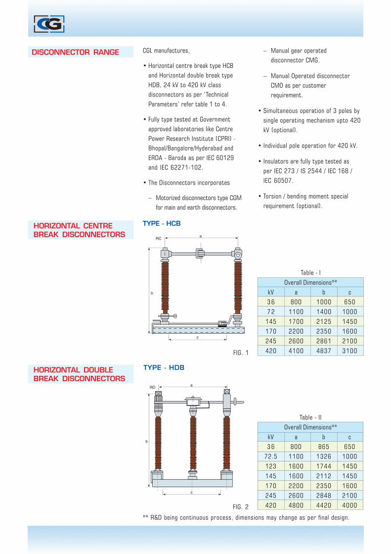
Table - IIOverall Dimensions**
kV a b c3 6 800 865 650
72.5 1100 1326 1000123 1600 1744 1450145 1600 2112 1450170 2200 2350 1600245 2600 2848 2100420 4800 4420 4000
Table - IOverall Dimensions**
kV a b c3 6 800 1000 6507 2 1100 1400 1000
145 1700 2125 1450170 2200 2350 1600245 2600 2861 2100420 4100 4837 3100
DISCONNECTOR RANGE CGL manufactures,
• Horizontal centre break type HCBand Horizontal double break typeHDB, 24 kV to 420 kV classdisconnectors as per ‘TechnicalParameters’ refer table 1 to 4.
• Fully type tested at Governmentapproved laboratories like CentrePower Research Institute (CPRI) -Bhopal/Bangalore/Hyderabad andERDA - Baroda as per IEC 60129and IEC 62271-102.
• The Disconnectors incorporates
– Motorized disconnectors type CGMfor main and earth disconnectors.
– Manual gear operateddisconnector CMG.
– Manual Operated disconnectorCMO as per customerrequirement.
• Simultaneous operation of 3 poles bysingle operating mechanism upto 420kV (optional).
• Individual pole operation for 420 kV.
• Insulators are fully type tested asper IEC 273 / IS 2544 / IEC 168 /IEC 60507.
• Torsion / bending moment specialrequirement (optional).
�
�
���
HORIZONTAL CENTREBREAK DISCONNECTORS
TYPE - HCB
HORIZONTAL DOUBLEBREAK DISCONNECTORS
�
�
���
TYPE - HDB
** R&D being continuous process, dimensions may change as per final design.
FIG. 1
FIG. 2

TECHNICAL PARAMETERS
Table - III Horizontal Centre Break Disconnectors Type - HCB
Table - IV Horizontal Double Break Disconnectors Type - HDB
Rated Rated Rated short Rated peak Power Frequency Lighting impulse Switching impulseVoltage Current Time current Short Withstand Voltage Withstand Voltage Withstand Voltage
Circuit current r.m.s 1min. 1.2/50µS 250/2500µS
To earth across isolating To earth across isolating To earth across isolatingdistance distance distance
kV A kA kAp kV kV kVp kVp kVp kVp
24 1250 25 62.5 50 80 125 195
36/38.5 1600 25 62.5 70 80 170 195
72.5 1600 40 100 140 160 325 375
123 1600 40 100 230 265 550 630
145 1600 40 100 275 315 650 750
170 2000 40 100 325 375 750 860
245 2000 40 100 460 530 1050 1200
300 4000 50 125 380 435 1050 1050(+170) 850 700(+245)
420 3150 50 125 520 610 1425 1425(+240) 1050 900(+345)
Rated Rated Rated short Rated peak Power Frequency Lighting impulse Switching impulseVoltage Current Time current Short Withstand Voltage Withstand Voltage Withstand Voltage
Circuit current r.m.s 1min. 1.2/50µS 250/2500µS
To earth across isolating To earth across isolating To earth across isolatingdistance distance distance
kV A kA kAp kV kV kVp kVp kVp kVp
36/38.5 1600 2 5 62.5 7 0 8 0 170 195
72.5 1600 4 0 100 140 160 325 375
123 1600 4 0 100 230 265 550 630
145 1600 4 0 100 275 315 650 750
170 2000 40 100 325 375 750 860
245 2000 4 0 100 460 530 1050 1200
300 4000 50 125 380 435 1050 1050(+170) 850 700(+245)
420 2000 5 0 125 520 610 1425 1425(+240) 1050 900(+345)
• Our field engineers offer supervision
services for erection, test and
commissioning of disconnectors upon
request.
• Existing disconnectors can be upgraded.
• Refurbishment of existing
disconnectors is undertaken on
request.
• Replacement of insulators for
pollution level improvement.
Disconnector are routine tested as per
IEC 62271-102 / IEC 60129.ROUTINE TESTS
INSTALLATION
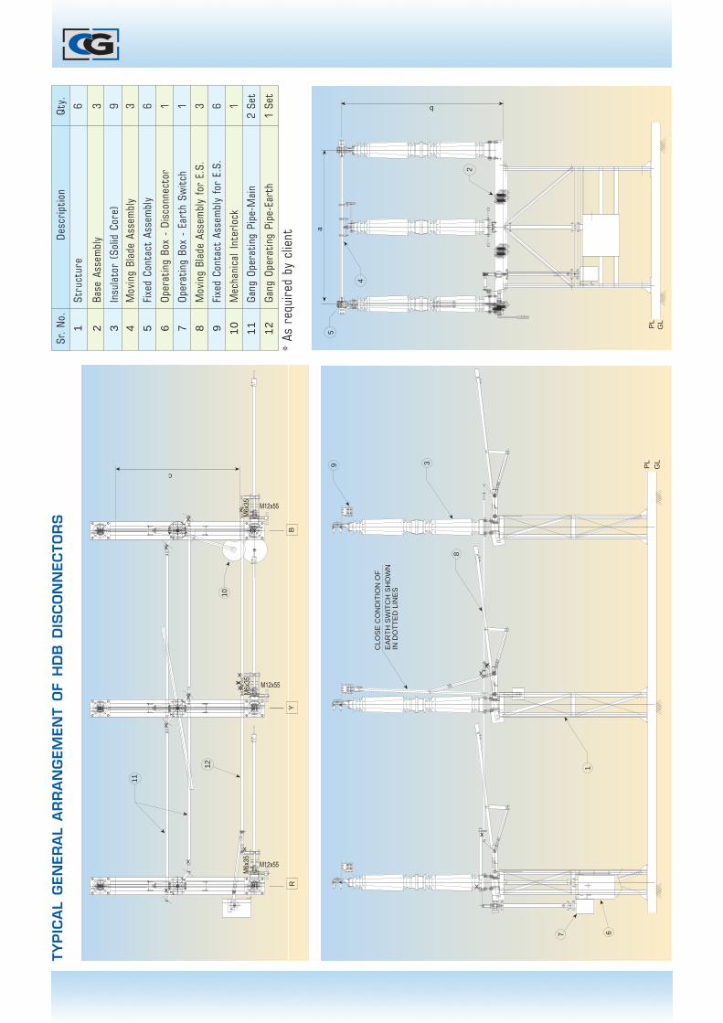
TY
PIC
AL
GEN
ER
AL
AR
RA
NG
EM
EN
T O
F H
DB
DIS
CO
NN
EC
TO
RS
Sr.
No.
Desc
ript
ion
Qty.
1St
ruct
ure
6
2Ba
se A
ssem
bly
3
3In
sula
tor
(Sol
id C
ore)
94
Mov
ing
Blad
e As
sem
bly
3
5Fi
xed
Cont
act
Asse
mbl
y6
6Op
erat
ing
Box
- Di
scon
nect
or1
7Op
erat
ing
Box
- Ea
rth
Swit
ch1
8M
ovin
g Bl
ade
Asse
mbl
y fo
r E.
S.3
9Fi
xed
Cont
act
Asse
mbl
y fo
r E.
S.6
10
Mec
hani
cal
Inte
rloc
k1
11
Gang
Ope
rati
ng P
ipe-
Mai
n2
Set
12
Gang
Ope
rati
ng P
ipe-
Eart
h1
Set
* As
req
uire
d by
clie
nt
x
x
x
11
10
R
M12x55
M6x
35
x
12
Y
M12x55
B
M12x55
c
x
x
x
M6x
35xx
x
xx
M6x
35
x
67
x
x
1
8
CLO
SE
CO
ND
ITIO
N O
FE
AR
TH
SW
ITC
H S
HO
WN
IN D
OT
TE
D L
INE
S
39 PL
GL
xxx
+++++++++ +++++++++
++++++++++++++++++
++++++++++++++++++
5
PL
GL
4
a
b
2
x

TY
PIC
AL
GEN
ER
AL
AR
RA
NG
EM
EN
T O
F H
CB
DIS
CO
NN
EC
TO
RS
Sr.
No.
Desc
ript
ion
Qty.
1In
sula
tor
6
2Ba
se A
ssem
bly
3
3Su
ppor
t St
ruct
ure
14
Oper
atin
g M
echa
nica
l - M
ain
1
5Ta
ndem
Pip
e2
6M
ale
Blad
e As
sem
bly
3
7Fe
mal
e Bl
ade
Asse
mbl
y3
8Ea
rth
Mov
ing
Blad
e3
9Ea
rth
Fixe
d Co
ntac
t3
10
Eart
h Ta
ndem
Pip
e2
11
Eart
h Op
erat
ing
Box
15
10
C
x
x
x
xx
8
4
PL
GL
x
x
9
FO
R C
LOS
ED
PO
SIT
ION
EA
RT
HIN
G S
WIT
CH
SH
OW
N IN
DO
TT
ED
CO
ND
ITIO
N.
1 2
A6
7
B 11
PL
PL
GL
GL
3

A/6+J1-
J2A/7
CONTROL VOLTAGE110V/220V, DC
MCB
K2
K1
K19 K2CC
K13
13 141L1 2T1
4T23L26T3
A/3
K115L3
2221
K29A/4
A/5
OCK2
OLRM8
MA2 A1
K23
M5
K11
14132T11L14T23L26T35L3
21 22
EXT.INT. 89Eb OLR-1A/8 A/9 K7 K9
K11A/16A/17
LS3
K3 A/40
EPB
K5
KIEC KIMC
A/41K2
K47
RLM
K45 K35 K33 A/12
MPB CPB
CPB
K13C/1
CC
-3
89b
A/10
OPB
OPB
K23 OC
-3
A/11B/1
89a
C/2K17
LSC
-11
K19CC
K27B/2
LS0-
10
K29OC
LATC
HING
CKT
EART
H SW
ITCH
MANU
AL I/L
LOCA
L CLO
SING
REMO
TE C
LOSI
NG
LOCA
L OPE
NING
LATC
HING
CKT
REMO
TE O
PENI
NG
ILLUMINATION CIRCUIT
HEATER CIRCUIT
RECEPTACLE CIRCUIT
240V
AC,
1Ø, 5
0Hz.
A/1 H1 MCB H3 HSWH5 TH H7 H
LSW
PSWH9
H11
L
PA/2H2 H4
A/13K93
LSO
-21
K95 K97
LSC
-20
A/14 A/15
IND
ICAT
ION
89 O
PEN
89 C
LOSE
IND
ICAT
ION
A/13K93
LSC-
20
LSO-
21
K95A/14 A/15
K97
89 O
PEN
INDI
CATI
ON
89 C
LOSE
INDI
CATI
ON
AUXILIARY SWITCH DIAGRAM89-a89-b
CM100M10
0M8CM8
0M4CM60M6
CM40M2CM2
0M20
0M18CM20
CM180M16CM16
CM140M14
0M12CM12
CM1
OM7CM7
OM3CM5OM5
CM3OM1
CM9
CM19OM19
OM17CM17
OM13
OM15CM15
CM13OM11CM11OM9
RECEPTACLE CIRCUIT
ILLUMINATION CIRCUIT
HEATER CIRCUIT
240V
AC,
1%%
C, 5
0Hz.A/1
A/2
H1
H2
MCB H3 H5 H7TB TH
H4H11H9 L
P
LSW
PSW
MOLROLR
OLR
M4M5M6
OCM1M2M3
1 23 45 63 421 22
CC1 23 45 63 421 22
MCB
RYB
N
415V AC 1%%C,50 Hz
A/6+J1-
J2A/7
K2
K1
MCBCONTROL VOLTAGE
110/220 V,DC
A/8EXT.INT.
A/9 K7A/17
89EbK9
OLR-1
A/16 K11
LS3 M
RL
A/40K3
EPB
K35K45 K33 A/12
CPB
MPB CP
B
CC-3
A/10K13K47K5
C/1
89b
OPB
OPB
K23 B/1
89a
OC-3
A/11
KIEC KIMC
K2 A/41
MANU
AL I/L
EART
H SW
ITCH
LOCA
L CLO
SING
K19
K17 C/2
LSC-
11
CC
REMO
TE C
LOSI
NG
LATC
HING
CKT
REMO
TE O
PENI
NG
LATC
HING
CKT
LOCA
L OPE
NING
K27
K29
B/2
LS0-
10
OC
Data subject to change DOM-1/DEC/4K/2005
South : Chennai
3, MGR Salai, Nugambakkam,Chennai - 600 034Tel : (044) 28257375Fax : (044) 28231973
Regional Head Quarters:
North : New Delhi
Vandana, 11, Tolstoy Marg,New Delhi - 110 001Tel : (011) 23730445Fax : (011) 23324360
East : Kolkata
50, Chowringhee Road,Calcutta - 700 071Tel : (033) 22829681Fax : (033) 22829942
West : Mumbai
Kanjur (East)Mumbai - 400 042Tel : (022) 25782451, 25795139Fax : (022) 25794882
Switchgear ComplexA-3, M.I.D.C., Ambad, Nasik - 422 010 - India.Tel : (+91) 253 2301661 to 73,Fax : (+91) 253 2382219 / 2381247E-mail : [email protected]
[email protected] (export)Web : www.cglonline.com
Regd. Office :6th Floor, CG House, Dr. Annie Besant Road,Worli, Mumbai - 400 030, India.
DISCONNECTOR CONTACTOR CONFIGURATION(AC MOTOR)
LEGEND DESCRIPTION MAKE
CC Closing Contactor 110/220V DC. Siemens/Telemecanique/ABB/Eq.
OC Opening Contactor 110/220V DC. Siemens/Telemecanique/ABB/Eq.
M Motor 0.5 Hp.110/220 V DCCG/Siemens/Remi/Polyphase/Eq.
OLR Overload Relay With SPP (1.0 To 1.4A) Telemecanique/Lakhsmi/Siemens/ABB/Eq.
KIMC Key Interlock Manual Contact CG/PS/Eq.
LSC Limit Switch Close 10A, 2NO+2NC Keycee/Jaibalaji/Concord/Eq.
LSO Limit Switch Open 10A, 2NO+2NC Keycee/Jaybalaji/Concord/Eq.
LMR Local/Manual/Remote Selector Switch Keycee/Switron/Teknic/Eq.CPB Close Push Button L & T/Teknic/Concord/Eq.OPB Open Push Button L & T/Teknic/Concord/Eq.MPB Manual Push Button L & T/Teknic/Concord/Eq.EPB Earth Push Button L & T/Teknic/Concord/Eq.H Heater(80W, 250V)2 Nos.each Of 40W. Velico/Eq.
HSW Heater Switch 5A. Anchor/Eq.TH Thermostat Velico/Mavis/Eq.
LSW Lamp Switch Anchor/Eq.MCB Miniature Circuit Breaker 110V DC. Schneider/Havels/Eq.89a Isolator Aux.contact-N/O Mani/Imax/Eq.89b Isolator Aux.contact-N/C Mani/Imax/Eq.P Switch Socket Unit 5/15 Amps Anchor/Eq.TB Terminal Block Winpar/Connectwell/Eq.
LEGEND DESCRIPTION MAKE
CC Closing Contactor 415V AC. Siemens/Telemecanique /ABB/Eq.
OC Opening Contactor 415V AC. Siemens/Telemecanique/ABB/Eq.
M Motor 0.5 Hp.Ø, 415V AC 50Hz. CG/Siemens/Remi/Polyphase/Eq.
OLR Overload Relay With SPP (1.0 To 1.4A) Telemecanique/Lakhsmi/Siemens/ABB/Eq.
KIMC Key Interlock Manual Contact CG/PS/Eq.
LSC Limit Switch Close 10A, 2NO+2NC Keycee/Jaibalaji/Concord/Eq.
LSO Limit Switch Open 10A, 2NO+2NC Keycee/Jaybalaji/Concord/Eq.
LMR Local/Manual/Remote Selector Switch Keycee/Switron/Teknic/Eq.CPB Close Push Button L & T/Teknic/Concord/Eq.OPB Open Push Button L & T/Teknic/Concord/Eq.MPB Manual Push Button L & T/Teknic/Concord/Eq.EPB Earth Push Button L & T/Teknic/Concord/Eq.H Heater (80W,250V)2 Nos.each Of 40W. Velico/Eq.
HSW Heater Switch 5A. Anchor/Eq.TH Thermostat Velico/Mavis/Eq.
LSW Lamp Switch Anchor/Eq.MCB Miniature Circuit Breaker 110V DC. Schneider/Havels/Eq.89a Isolator Aux.contact-N/O Mani/Imax/Eq.89b Isolator Aux.contact-N/C Mani/Imax/Eq.P Switch Socket Unit 5/15 Amps Anchor/Eq.
HSW Terminal Block Elmex/Connectwell/Eq.
(DC MOTOR)
Sang
am