skid steer grader blade - spartan equipment. skid steer grader blade safety instructions tractor...
TRANSCRIPT
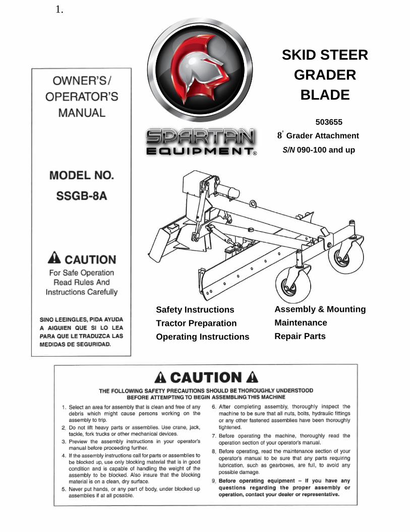
1.
SKID STEER
GRADER
BLADE
Safety Instructions
Tractor Preparation
Operating Instructions
Assembly & Mounting
Maintenance
Repair Parts
503655
8’ Grader Attachment
S/N 090-100 and up


SINO LEEINGLES, PIDA AYUDA A
AIGUIEN QUE SI LO LEA PARA QUE
LE TRADUZCA LAS MEDIDAS DE
SEGURIDAD,
STATEMENT
OF POLICY
It is the policy of Spartan
Equipment to improve its products
where it is possible and practical
to do so. Spartan Equipment
reserves the right to make
changes or improvements in
design and construction at any
time, without incurring the obliga-
tion to make these changes on
previously manufactured units.
TO THE OWNER:
Read this manual before using your Grader Blade. This manual is provided to give you the necessary operating
and maintenance instructions for keeping your Grader Blade in top operating condition. Please read this manual
thoroughly. Understand what each control is for and how to use it. Observe all safety signs on the machine and
noted throughout the manual for safe operation of implement. Keep this manual handy for ready reference.
Like all mechanical products, it will require cleaning and upkeep. Lubricate the Grader Blade as specified.
Use only genuine Spartan Equipment, Inc. service parts. Substitute parts will void the warranty and may not meet
standards required for safe and satisfactory operation. Record the model and serial number of your Grader Blade
here:
Model: _________________________________________ Serial Number: ______________________________ _
RETAIL CUSTOMER'S RESPONSIBILITY
It Is the Retail Customer and/or Operator's responsibility to read the Operator's Manual, to operate, lubricate, maintain, and store the product in accordance with all Instructions and safety procedures. Failure of the
operator to read the Operator's Manual is a misuse of this equipment.
It is the Retail Customer and/or Operator's responsibility to inspect the product and to have any part(s) repaired or replaced when continued operation would cause damage or excessive wear to other parts or
cause a safety hazard.
It is the Retail Customer's responsibility to deliver the product to the authorized Spartan Equipment Dealer, from whom he purchased It, for service or replacement of defective parts which are covered by warranty.
Repairs to be submitted for warranty consideration must be made within forty-five (45) days of failure.
It is the Retail Customer's responsibility for any cost incurred by the Dealer for traveling to or hauling of the product for the purpose of performing a warranty obligation or inspection.

LIMITED WARRANTY Spartan Equipment warrants to the original purchaser of any new Grader Blade Model SSGB-8A, that the
equipment be free from defects in material and workmanship for a period of TWELVE (12) MONTHS
COMMENCING ON THE DATE OF DELIVERY OF THE PRODUCT TO THE ORIGINAL PURCHASER. This
warranty will apply if notified to Spartan Equipment, Inc. within thirty (30) days after such defect is discovered.
The warranty registration must be completed and returned to Spartan Equipment.
Replacement or repair parts installed in the equipment covered by this warranty are warranted for ninety (90)
days from the date of purchase of such part or to the expiration of the applicable new equipment warranty period,
whichever occurs later.
Such parts shall be provided at no cost to the user during regular working hours. Spartan Equipment reserves the
right to inspect any equipment or parts which are claimed to have been defective in material or workmanship.
This warranty is extended solely to the original purchaser of the product. Should the original purchaser sell or
otherwise transfer this product to a third party, this warranty does not transfer to the third party purchaser in any
way. There are no third party beneficiaries of this warranty.
DISCLAIMER OF IMPLIED WARRANTIES & CONSEQUENTIAL DAMAGES
Spartan Equipment shall not be liable for any incident or consequential losses, damages or expenses, arising
directly or indirectly from the product, whether such claim is based upon breach of contract, breach of warranty,
negligence, strict liability in tort or any other legal theory.
Spartan Equipment's obligation under this warranty, to the extent allowed by law, is in lieu of all warranties,
implied or expressed, including implied warranties of merchantability and fitness for a particular purpose and any
liability for incidental and consequential damages with respect to the sale or use of the items warranted. Such
incidental and consequential damages shall include but not be limited to: transportation charges other than
normal freight charges; cost of installation other than cost approved by Spartan Equipment; duty; taxes; charges
for normal service or adjustments; loss of crops or any other loss of income; rental of substitute equipment,
expenses due to loss, damage, detention or delay in the delivery of equipment or parts resulting from acts
beyond the control of Spartan Equipment.
THIS WARRANTY SHALL NOT APPLY:
1. To vendor items which carry their own warranties, such as hydraulic cylinders, tires, and laser control
systems.
2. If the unit has been subjected to misapplication, abuse, misuse, negligence, fire or other accident.
3. If parts not made or supplied by Spartan Equipment have been used in connection with the unit, if, in sole
judgement of Spartan Equipment such use affects its performance, stability, or reliability.
4. If the unit has been altered or repaired outside of an authorized Spartan Equipment dealership in a manner
which, in the sole judgement of Spartan Equipment affects its performance, stability or reliability.
5. To normal maintenance service and normal replacement items such as gearbox lubricant, hydraulic fluid,
worn blades, or to normal deterioration of such things as hoses and exterior finish, due to use or exposure.
6. To expendable or wear items such as cutting edge, plow bolts, springs and other items that in the company's
sole judgement is a wear item.
2

To the Owner/Operator/Dealer All implements with moving parts are potentially hazardous. There is no substitute for a cautious, safe-minded operator
who recognizes the potential hazards and follows reasonable safety practices. The manufacturer has designed this
implement to be used with all its safety equipment properly attached to minimize the chance of accidents.
BEFORE YOU START!! Read the safety messages on the implement and shown in your manual.
Observe the rules of safety and common sense!
THIS SAFETY ALERT SYMBOL IDENTIFIES IMPORTANT
SAFETY WARNING MESSAGES. CAREFULLY READ EACH
WARNING MESSAGE THAT FOLLOWS. FAILURE TO
UNDERSTAND AND OBEY A SAFETY WARNING, OR RECOGNIZE A SAFETY HAZARD, COULD RESULT IN AN
INJURY OR DEATH TO YOU OR OTHERS AROUND YOU.
THE OPERATOR IS ULTIMATELY RESPONSIBLE FOR THE
SAFETY OF HIMSELF, AS WELL AS OTHERS, IN THE
OPERATING AREA OF THE SKID STEER AND AITACHED
EQUIPMENT.
THIS SYMBOL MEANS -
ATTENTION!
- BECOME ALERT!
- YOUR SAFETY IS INVOLVED!
UNDERSTAND SIGNAL WORDS
Note the use of the signal words DANGER, WARNING
and CAUTION with the safety messages. The
appropriate signal word for each has been selected
using the following guidelines:
WARNING: Indicates a potentially hazardous sit-
uation that, if not avoided, could result in death or
serious injury, and includes hazards that are
exposed when guards are removed. It may also be
used to alert against unsafe practices.
DANGER: Indicates an imminently hazardous situation
that, if not avoided, will result in death or serious injury.
This signal word is to be limited to the most extreme
situations typically for machine components which, for
functional purposes, cannot be guarded.
CAUTION: Indicates a potentially hazardous sit-
uation that, if not avoided, may result in minor or
moderate injury. It may also be used to alert
against unsafe practices.
If you have questions not answered in this manual or require additional copies or the manual is damaged, please contact
your dealer or the manufacturer directly.
IMPORTANT SAFETY INFORMATION!
Working with unfamiliar equipment can lead to careless injuries. Read this manual, and the manual for your tractor, before
assembly or operating, to acquaint yourself with the machines. It is the implement owner's responsibility, if this machine is
used by any person other than yourself, is loaned or rented, to make certain that the operator, prior to operating:
1. Reads and understands the operator's manuals.
2. Is instructed in safe and proper use.
The use of this equipment is subject to certain hazards which cannot be protected against by mechanical means
or product design. All operators of this equipment must read and understand this entire manual, paying particular
attention to safety and operating instructions, prior to using. If there is something in this manual you do not
understand, ask your supervisor, or your dealer, to explain it to you.
3

SAFETY INSTRUCTIONS (continued)
EQUIPMENT SAFETY GUIDELINES
Safety of the operator is one of the main concerns in designing and developing a new piece of equipment.
Designers and manufacturers build in as many safety features as possible. However, every year many accidents
occur which could have been avoided by a few seconds of thought and a more careful approach to handling
equipment. You, the operator, can avoid many accidents by observing the following precautions in this section.
To avoid personal injury, study the following precautions and insist those working with you, or for you, follow
them.
In order to provide a better view, certain photographs or illustrations in this manual may show an assembly with a
safety shield removed. However, equipment should never be operated in this condition. Keep all shields in place.
If shield removal becomes necessary for repairs, replace the shield prior to use.
Replace any CAUTION, WARNING, DANGER or instruction safety sign that is not readable or is missing.
Location of such safety signs is indicated in this booklet.
Never use alcoholic beverages or drugs which can hinder alertness or coordination while operating this
equipment. Consult your doctor about operating this machine while taking prescription medications.
Review the safety instructions with all users annually.
This equipment is dangerous to children and persons unfamiliar with its operation. The operator should be a
responsible adult familiar with farm machinery and trained in this equipment's operations. Do not allow persons
to operate or assemble this unit until they have read this manual and have developed a thorough
understanding of the safety precautions and of how it works.
Do not paint over, remove or deface any safety signs or warning signs on your equipment. Observe all safety
signs and practice the instruction on them.
Never exceed the limits of a piece of machinery. If its ability to do a job, or to do so safely, is in question - DON'T
TRY IT.
Do not modify the equipment in any way. Unauthorized modification may impair the function and/or safety and
could affect the life of the equipment.
In addition to the design and configuration of this implement, including Safety Signs and Safety Equipment,
hazard control and accident prevention are dependent upon the awareness, concern, prudence, and proper
training of personnel involved in the operation, transport, maintenance, and storage of the machine. Refer also to
Safety Messages and Operation Instructions in each of the appropriate sections of the Skid Steer and
Attachment Manuals. Pay close attention to the Safety Signs affixed to the Skid Steer and the Attachment.
4

SAFETY INSTRUCTIONS (continued)
5
SAFETY INSTRUCTIONS (continued)
STARTING AND STOPPING SAFETY
Be certain the skid steer is in neutral or park position before starting engine.
Do not leave the skid steer or the attachment unattended with the engine running.
Grader blade operating power is supplied from skid steer hydraulic system. Refer to your skid steer manual for
hydraulic engagement and disengagement instructions. Know how to stop skid steer and grader controls quickly
in case of an emergency.
Grader blade should be on the ground before engaging hydraulic power and be sure that no one is near the machine. When engaging hydraulic system, the RPM should always be low.
Take all possible precautions when leaving unit unattended: Disengage hydraulic power, set parking brake, stop engine and remove key from ignition. Park in level area.
OPERATIONAL SAFETY
The use of this equipment is subject to certain hazards which cannot be protected against by mechanical means
or product design. All operators of this equipment must read and understand this entire manual, paying particular
attention to safety and operating instructions, prior to using. If there is something in this manual you do not
understand, ask your supervisor, or your dealer, to explain it to you.
Most accidents occur because of neglect or carelessness. Keep all helpers and bystanders at least twenty (20) feet from an operating grader. Only properly trained people should operate this machine.
Avoid uneven and rough terrain. DO NOT operate near drop off, ditches, or embankments. Unit can suddenly turn over if a wheel is over the edge of a cliff or ditch, or if an edge caves in.
Do not walk or work under a raised skid steer attachment unless it is securely blocked or held in position. Do not depend on the hydraulic system to hold the skid steer attachment in place.
A heavy load can cause instability of the skid steer. Use extreme care during travel. Slow down on turns and watch out for bumps. The skid steer may need additional counter-weights to counter-balance the weight of the grader blade attachment.
Never use alcoholic beverages or drugs which can hinder alertness or coordination while operating this equipment. Consult your doctor about operating this machine while taking prescription medications.
Never permit any person other than the operator to ride or board the skid steer or grader blade attachment at any time. ALLOW NO RIDERS!
6

SAFETY INSTRUCTIONS (continued)
OPERATIONAL SAFETY (continued)
Before you operate the grader blade, check over all pins, bolts and connections to be sure all are securely in
place. Replace any damaged or worn parts immediately.
Consult local utility companies to make certain there are no buried gas lines, electrical cables, etc., in the work
area before beginning operation.
Use extreme care and maintain minimum ground speed when transporting on hillside, over rough ground and
when operating close to ditches or fences. Be careful when turning sharp corners.
Avoid sudden starts and stops while traveling up or downhill. Avoid parking on a slope.
Always drive down slopes; never across the face. Avoid operation on steep slopes. Slow down on sharp turns
and slopes to prevent tipping and/or loss of control. Avoid slopes when surface is wet, slippery grass or soil. Be
careful when changing directions on slopes. Do not start or stop suddenly on slopes.
Keep work area clear of all debris. Debris could damage the unit. Never assume an area is clear. ALWAYS
CHECK.
Inspect the entire machine periodically as indicated in the Maintenance Section of this manual. Look for loose
fasteners, worn or broken parts and/or shields. Make sure all pins have cotter pins and washers. Serious injury
may occur from not maintaining this machine in good working order.
Most accidents occur because of neglect or carelessness. Keep all helpers and bystanders at a safe distance.
Make sure children are out of work area and under watchful care of a responsible adult.
Beware of low electrical wires if grader blade attachment is raised with skid steer loader. Serious injury or death
can result if contact is made. Beware of lift clearance when raising grader blade to maximum height.
Keep alert and watch the rear as well as the front when working with the grader blade. Watch for traffic when
operating along streets or curbs.
When maneuvering close to buildings or passing through narrow areas, be sure to allow sufficient clearance for
the skid steer and attachment. Drive slowly.
7

Operate grader blade from operator's seat only. Remain at controls until operating cycle is complete.
Stop skid steer loader gradually when lowering or lifting loads. Operate skid steer and grader blade controls smoothly, avoid jerky operation.
Allow for additional length of loader arms and attachment on skid steer while turning.
Be sure that people, livestock, or pets are not standing near the machine while operating.
Avoid excessive speed during operation.
Do not lift or carry anyone on loader or in bucket or on attachment. Do not use grader blade for a work platform.
ALWAYS lower loader and grader blade attachment to the ground or block securely before performing any maintenance work.
Stay alert for holes, rocks and roots in the terrain and other hidden hazards. Keep away from drop-offs.
Use extra care when loading or unloading grader blade onto trailer or truck. NEVER secure rods or linkages on unit that could be damaged when transporting.
Before operating equipment: if you have any questions regarding the proper assembly or operation, contact your dealer or representative.
8

SAFETY INSTRUCTIONS (continued)
MAINTENANCE SAFETY
Before working on this machine, drive to a level area, relieve hydraulic pressure, lower implement (or if working
underneath, raise and block securely), shut off the engine, set the brakes, and remove the ignition keys. Relieve
hydraulic pressure prior to doing any maintenance.
Never work under equipment unless it is blocked securely. Never depend on hydraulic system to keep implement
in raised position.
Keep a" persons away from operator control area while performing adjustments, service, or maintenance.
Make sure there is plenty of ventilation. Never operate the engine of the vehicle in a closed building. The exhaust
fumes may cause asphyxiation.
Always use personal protection devices such as eye, hand and hearing protectors, when performing any service
or maintenance.
Never use your hands to locate a hydraulic leak on attachments. Use a small piece of cardboard or wood.
Hydraulic fluid escaping under pressure can penetrate the skin.
Openings in the skin and minor cuts are susceptible to infection from hydraulic fluid. If injured by escaping
hydraulic fluid, see a doctor at once. Gangrene and death can result. Without immediate medical treatment,
serious infection and reactions can occur.
Periodically tighten a" bolts, nuts and screws and check that a" cotter pins are properly installed to ensure unit is
in a safe condition.
When completing a maintenance or service function, make sure a" safety shields and devices are installed before
placing unit in service.
Always use two people to handle heavy, unwieldy components during assembly, installation, removal, or moving
the grader blade attachment
Check to ensure all safety signs are installed and in good condition. (See safety sign section for location
drawing.)
Good maintenance is your responsibility. Poor maintenance is an invitation to trouble.
9

Comply with state and local laws governing highway safety and movement of machinery on public roads.
The use of flashing amber lights is acceptable in most localities. However, some localities prohibit their use. Local laws should be checked for all highway lighting and marking requirements.
Always be sure the attachment is in the proper raised position for transport.
If grader unit is loaded on a truck or trailer for transport, make sure unit is securely tied down. NEVER tie to rods or linkage parts that could be damaged.
Reduce speed when transporting mounted attachments to avoid bouncing and momentary loss of steering control.
Plan your route to avoid heavy traffic.
Do not drink and drive!
Watch for traffic when operating near or crossing roadways.
Never allow riders on either skid steer or attachment. Falling off can kill.
Be a safe and courteous driver. Always yield to oncoming traffic in all situations, including narrow bridges, inter-sections, etc.
STORAGE SAFETY
Store the unit in an area away from human activity. Do not permit children to play on or around the stored unit.
Make sure all parked machines are on a hard, level surface and engage all safety devices. Storage location should be level and solid to make connecting and unconnecting to skid steer easy.
If blocking is used, make sure it is solid and secure before leaving area.
10

SAFETY SIGNS
REMEMBER: If Safety Signs have been damaged, removed, become illegible or parts replaced without Signs, new Safety Signs must be applied. New Safety Signs are available from your authorized distributor or factory.
11

SAFETY SIGN LOCATION
The types of safety signs and locations on the equipment are shown in the illustration below.
Good safety requires that you familiarize yourself with various safety signs, the type of warning
and the area, or particular function related to that area, that requires your SAFETY
AWARENESS.
2
1
Ref. Part No. Description
No.
No. Req'd. 1 101289 Safety Sign - Warning (Avoid Serious Injury) 1
2 101290 Safety Sign - Caution (Getting On and Off) 1
3 101288 Safety Sign - Warning (Crushing and Pinching) 1
4 101122 Safety Sign - Warning (High-Pressure Fluid) 1
5 101027 Safety Sign - Warning (Stand Clear) 2
6 101291 Safety Sign - Caution (No Step) 1
The model and serial number plate is located on the right side of the vertical
part of the main frame.
The serial number is also stamped into the top cross tube of the skid steer
mounting frame.
12

INSTRUCTIONS
SKID STEER REQUIREMENTS AND PREPARATION
The Model SSGB-8A Grader Blade is designed to fit
skid steer units with the "Universal" style quick-attach
loaders.
Remove the bucket from your Skid Steer unit. Check the
loader arms and cylinders to make sure they are in good
working order. Lubricate all loader pivot points. Check all
bolts to make sure they are in place and tight.
Be sure the skid steer hydraulic oil and filter have been
serviced according to the skid steer manufacturer's
recommendations.
CAUTION!
Be sure your skid steer is in good condition. Read
all the safety precautions and make sure all skid
steer operators are familiar with the safety rules of
operation.
Check the skid steer tires. The rear tires are used to
operate the skid steer with the grader blade attachment
and should have good tread. Adjust tire pressure to 50 psi
(346 KN/m2). Keep tire valves capped.
If an optional laser control is used, see manual
provided with laser unit for installation and operating
instructions.
NOTE: Read section on hydraulic valve - page 16.
ASSEMBLY
This unit is shipped almost completely assembled. Carefully follow instructions for final assembly.
Before attempting assembly check the following items.
Having all the needed parts and equipment readily at hand
will speed up your assembly task and will make the job as
safe as possible.
Check for fasteners and pins that were shipped with the
grader blade. All hardware coming from the factory has
been installed in the location where it will be used. If a
part or fastener is temporarily removed for assembly
reasons, remember where it goes. Keep the parts
separated.
• Have a minimum of 2 people at hand during assembly.
Refer to the "exploded view" of the skid steer mounted
grader blade on page 22 of this manual. Become familiar
with the relationship of the various components and parts
shown.
The caster wheel assemblies have been removed for
shipping. Clean the vertical caster fork spindles and
smear grease on the spindles before assembly. Fasten
with the lock collar and make sure set screw bolt goes into
countersunk hole in spindle. Then connect grease gun to
grease zerk and apply until excess grease appears.
The hydraulic cylinder has been disconnected from the
blade to allow a narrow shipping profile.
After the grader blade is attached to the skid steer,
manually position the blade so the pin can connect the
cylinder rod end to the shearpin arm of the blade.
GRADER INSTALLATION I REMOVAL
To install:
1. Read and understand skid steer manufacturer's
instructions for installing attachments.
2. Make sure attachment pins are in "unlock" position in
skid steer mounting plate.
3. Line up skid steer and grader on level ground.
4. Tilt skid steer attachment mounting plate to fit grader
mounting plate.
5. Move skid steer forward and raise skid steer mounting
plate until it meets grader mounting plate with skid steer
mounting plate tilted slightly forward.
6. Raise skid steer mounting plate until the grader blade
leaves the ground.
7. Tilt skid steer mounting plate back to secure grader
mounting plate.
8. Turn off skid steer and make sure auxiliary hydraulic
controls are off (see skid steer manual).
9. Lock grader to skid steer. Flip the spring loaded latch
pins to the "latch lock" position and check to see they
are properly latched.
13

INSTRUCTIONS (continued,
GRADER INSTALLATION I REMOVAL (continued,
10. Attach the grader hydraulic hose with the female con-
nector to the skid steer auxiliary hydraulic hose with
male connector.
IMPORTANT: Make sure connectors are clean prior to
installation.
11. Attach the grader hydraulic hose with the male con-
nector to the skid steer auxiliary hydraulic hose with
the female connector.
12. Route the hose to avoid pinching or chafing the hose.
Use nylon ties or tape to fasten hose on loader arm to
keep it in place. Make sure the hose routing and
length is adequate for your particular make and model
skid loader.
DANGER!
Escaping hydraulic fluid under pressure can penetrate
the skin, causing serious injury.
DO NOT use your hand to check for leaks. Use a piece
of cardboard or paper to search for leaks.
Stop engine and relieve pressure before connecting or
disconnecting lines.
Tighten all connections before starting engine or
pressurizing lines.
If any fluid is injected into the skin, obtain medical
attention immediately, or gangrene may result.
13. Mount grader control panel to skid steer with hardware provided.
14. Connect black battery wire from grader to skid steer
negative battery terminal. Connect red wire to skid
steer positive battery terminal.
15. Test grader for proper hydraulic flow. Change position
of auxiliary hydraulic control on skid steer if grader
does not respond. (See skid steer operation manual).
NOTE: Grader has a check valve so hydraulic oil can only
flow correctly.
To Remove Grader From Skid Steer:
1. Turn off skid steer and make sure auxiliary hydraulic
controls are off (see skid steer manual).
2. Disconnect battery wires from battery terminals, starting
with the negative wire. Disconnect grader control panel
box wiring.
3. Disconnect auxiliary hydraulic hoses. Cap all hoses.
4. Unlatch skid steer attachment pins from grader mount-
ing plate.
5. Lower skid steer attachment mounting plate to the
ground.
6. Tilt skid steer attachment mounting plate forward and
back skid steer away from grader.
GRADER BLADE CONTROL PANEL
The grader blade control panel is intended to mount
vertically inside the skid steer for easy accessibility on the
operator's left side.
The Grader has four control switches:
Grader Blade Rotation Switch (1)
Press the rotation switch up to rotate the grader blade
clockwise. Press the rotation switch down to rotate the
grader blade counterclockwise.
Laser Power Switch (2)
If unit is equipped with laser, press the laser power switch
up to turn on. Press the laser power switch down to turn
off.
Right-Side Lift Switch (3)
Press the right-hand lift switch up to raise the right side of
the grader blade. Press the right-hand lift switch down to
lower the right side of the grader blade.
Left-Side Lift Switch (4)
Press the left-hand lift switch up to raise the left side of the
grader blade. Press the left-hand lift switch down to lower
the left side of the grader blade.
14
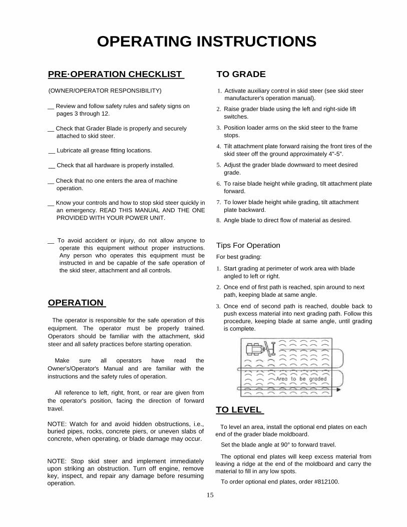
OPERATING INSTRUCTIONS
PRE·OPERATION CHECKLIST
(OWNER/OPERATOR RESPONSIBILITY)
__ Review and follow safety rules and safety signs on
pages 3 through 12.
__ Check that Grader Blade is properly and securely
attached to skid steer.
__ Lubricate all grease fitting locations.
__ Check that all hardware is properly installed.
__ Check that no one enters the area of machine
operation.
__ Know your controls and how to stop skid steer quickly in
an emergency. READ THIS MANUAL AND THE ONE
PROVIDED WITH YOUR POWER UNIT.
__ To avoid accident or injury, do not allow anyone to
operate this equipment without proper instructions.
Any person who operates this equipment must be
instructed in and be capable of the safe operation of
the skid steer, attachment and all controls.
OPERATION
The operator is responsible for the safe operation of this
equipment. The operator must be properly trained.
Operators should be familiar with the attachment, skid
steer and all safety practices before starting operation.
Make sure all operators have read the
Owner's/Operator's Manual and are familiar with the
instructions and the safety rules of operation.
All reference to left, right, front, or rear are given from
the operator's position, facing the direction of forward
travel.
NOTE: Watch for and avoid hidden obstructions, i.e., buried pipes, rocks, concrete piers, or uneven slabs of
concrete, when operating, or blade damage may occur.
NOTE: Stop skid steer and implement immediately upon striking an obstruction. Turn off engine, remove key, inspect, and repair any damage before resuming operation.
TO GRADE
1. Activate auxiliary control in skid steer (see skid steer
manufacturer's operation manual).
2. Raise grader blade using the left and right-side lift
switches.
3. Position loader arms on the skid steer to the frame
stops.
4. Tilt attachment plate forward raising the front tires of the
skid steer off the ground approximately 4"-5".
5. Adjust the grader blade downward to meet desired
grade.
6. To raise blade height while grading, tilt attachment plate
forward.
7. To lower blade height while grading, tilt attachment
plate backward.
8. Angle blade to direct flow of material as desired.
Tips For Operation
For best grading:
1. Start grading at perimeter of work area with blade
angled to left or right.
2. Once end of first path is reached, spin around to next
path, keeping blade at same angle.
3. Once end of second path is reached, double back to
push excess material into next grading path. Follow this
procedure, keeping blade at same angle, until grading
is complete.
TO LEVEL
To level an area, install the optional end plates on each
end of the grader blade moldboard.
Set the blade angle at 90° to forward travel.
The optional end plates will keep excess material from
leaving a ridge at the end of the moldboard and carry the
material to fill in any low spots.
To order optional end plates, order #812100.
15

OPERATING INSTRUCTIONS (continued)
HYDRAULIC VALVES
The Model SSGB-SA grader blade starting with SIN
090-100 is equipped with a proportional current (PC) type
hydraulic valve. This valve provides smoother movement
with the hydraulic cylinders.
Prior grader blade models use an onloff type hydraulic
valve.
NOTE: Some laser receivers may not work with the new
proportional current type valve. The Trimble" Model GCR-
1 SM Laser receiver is not compatible with the proportional
current valve. Check with your laser supplier for which
models are compatible.
SHEARPIN PROTECTION
There is an arm (part #S119S1) that connects the
moldboard weldment of the grader to the hydraulic cylinder
that angles the blade assembly.
This arm is connected to the moldboard weldment by a
5/16" X 2 1/2" standard clevis pin (part #2504244 - pkg. of
10).
These pins are available from the grader manufacturer.
In an emergency, you may use a 5/16" X 2 1/2" long Grade
2 bolt. DO NOT USE anything harder than a Grade 2 bolt!
Use of a hard bolt may result in damage to the machine.
TRANSPORTING
CAUTION!
When traveling on public roads, whether at night or
during the day, use accessory light and devices for
adequate warnings to operators of other vehicles.
Comply with all federal, state and local laws.
When Travelling To Another Work Area:
1. Tilt adjustment plate backward to place the front tires of
the skid steer back on the ground.
2. Lift loader arms off the frame stops.
3. Raise grader blade.
4 Drive to new work area.
Check visibility. If visibility is impaired, reduce speed or
consider other means of transport.
Allow for additional length of loader and attachment on
skid steer while turning.
Select a safe ground travel speed when transporting
from one area to another. When traveling on roadways,
transport in such a way that faster moving vehicles may
pass you safely.
When traveling over rough or hilly terrain or when
making turns, slow down and use extra care.
Read all the safety warnings in the front of this manual
and in the manual of skid steer.
Transporting Unit On Truck Or Trailer:
The unit may be lifted and moved by a crane.
1. Disconnect grader from skid steer unit.
2. Secure crane hook to lift lug located on top of main
frame.
3. Lift the entire unit off the ground and carefully load on
truck or trailer.
If transporting unit on a trailer, tie down the unit by the
torsion tube and the mounting plate.
Use extra care when loading for unloading unit onto
trailer or truck.
NEVER secure rods or linkages on unit that could be
damaged when securing grader to transport vehicle.
16

OWNER SERVICE
MAINTENANCE
The information in this section is written for operators
who possess basic mechanical skills. If you need help,
your dealer has trained service technicians available.
For your protection, read and follow the safety
information in this manual.
WARNING!
NEVER GO UNDERNEATH EQUIPMENT. Never
place any part of the body underneath equipment or
between moveable parts even when the engine has
been turned off. Hydraulic system leak down, hydraulic
system failures, mechanical failures, or movement of
control levers can cause equipment to drop or rotate
unexpectedly and cause severe injury or death.
Read Manual for service instructions or have
service performed by a qualified dealer.
WARNING!
Keep all persons away from operator control area
while performing adjustments, service, or maintenance.
Before dismounting power unit or performing any
service or maintenance, follow these steps: disengage
power to equipment, lower all raised components to the
ground, operate valve levers to release any hydraulic
pressure, set parking brake, stop engine, remove key,
and unfasten seat belt. Never leave equipment
unattended with engine running.
Check hydraulic hoses and fittings for leaks. Repair
any leaks immediately. Never use your hand to check
for a hydraulic leak when system is under pressure.
Thoroughly clean the grease zerks before servicing.
Dirt mixed with lubricant will rapidly wear parts. Keep it
clean.
Periodically check all bolts to make sure they are tight.
Check hydraulic hoses. Make sure they are not
chafed or pinched. Replace any damaged hose.
Replace any worn or damaged parts immediately.
Do not use attachment with any damaged parts.
Replace safety signs and instruction decals if
damaged or missing.
Replacing Cutting Edge
The grader blade uses a 'Ii' x 6" (12.7 x 152 mm)
cutting edge. It is reversible.
1. Raise the blade.
2. Place a 4" x 4" block under the lower moldboard
support. Then lower the blade so the lower
moldboard support rests securely on the block.
3. Place two smaller blocks under the cutting edge so
when the cutting edge is loose from the blade it
doesn't fall directly on the ground (these blocks will
also support the cutting edge when bolting it back on
the blade).
NOTE: Do not block the machine any higher than
necessary to remove cutting edge.
4. Refer to the Parts Drawings/Schematics on pages
21 and 22 for proper parts identification. Remove
the hex nuts and plow bolts that are securing the
cutting edge to the moldboard. Turn the cutting edge
over and use the new edge, or replace it if both
edges have been used.
5. Attach the cutting edge to the blade and secure with
plow bolts and hex nuts previously removed.
6. Torque plow bolts to specifications given in Bolt
Torque Chart, page 30.
17

2. SERVICE INSTRUCTIONS (continued)
GREASE LOCATIONS
GRADER LUBRICATION
Thoroughly clean the grease zerks before servicing. Dirt
mixed with lubricant will rapidly wear parts. Keep it clean.
Use a lithium grease of No.2 consistency with a MOLY
(molybdenum disulfide) additive for all locations.
Lubricate the following points:
1. Blade Pivot Spindle
2. Caster Pivot Spindles
3. Front Axle Pivot.
4. Torsion Beam Pivot (Vertical)
5. Torsion Beam Pivot (Tilt)
6. Caster Wheel Hubs
CHECK TIRE PRESSURE
Adjust the tire pressure for all tires to 50 psi (346
KN/m2). Keep tire valves capped.
CHECK HYDRAULIC LINES
Check the hydraulic lines every 100 operating hours.
Inspect hoses for wear, cracks, loose connections, leaks,
etc. Repair hoses as needed.
2
STORAGE
At the end of the working season or when the Grader
Blade will not be used for a long period, it is good
practice to clean off any dirt or grease that may have
accumulated.
Inspect the Grader Blade for loose, damaged or worn
parts and adjust or replace if needed.
Always store in a clean, dry location away from children
and livestock.
Storage location should be level and solid to make
hitching and unhitching easy.
• Grease the unit.
• Check and adjust the tire pressure.
• Place plastic caps on the hydraulic hose ends.
• Check all bolts, nuts, screws and tighten.
• Touch up all areas where paint has been removed.
• Cover the unit to keep it clean.
IMPORTANT: Moving hydraulic hoses should be replaced every two years or as wear dictates. • Coat hydraulic cylinder rods with lithium based grease.
18

TROUBLE·SHOOTING GUIDE
19

TROUBLE·SHOOTING GUIDE (continued)
20

3.
SSGB·8A GRADER BLADE HYDRAULIC DIAGRAM & PARTS LIST
Parts List Item Qty. Part Number Description
1 3 2505663 Cylinder, Hyd. 2 x 12 1 2504239 Cylinder Seal Kit
2 4 2505692 Hose, Hyd. 1/4" x 23"
3 12 2505696 Adapter, Hyd. 90 Deg. Adj. Elbow 7/16" 4 1 2505694 Hose, Hyd. 1/4" x 51" 5 1 2505693 Hose, Hyd. 1/4" x 47"
6 2 2505695 Hose, Hyd. 3/4" x 65"
7 1 2505691 Check Valve, SAE 12 (1-1/16" - 12UN) 8 1 2505661 Coupler, Flat Face, 1/2 NPT, Female 9 1 2505662 Coupler, Flat Face, 1/211 NPT, Male
10 1 2505714 Hydraulic Valve, Proportional Current
11 6 2505730 Replacement Coil. 12V DC 12 3 2503011 Bolt 3/8"-16NC x 1" Hex Head Gr. 2
13 3 2502008 Washer 3/8" Sprinqlock
14 3 2505731 Renlacement Spool (Solenoid)
21

SSGB·8A GRADER BLADE PART5 DRAWING
22

GRADER BLADE PARTS LIST
Ref. Part No. Description
No.
No. Req'd.
1 811905 Main Frame Weldment 1
2 811920 Torsion Tube Weldment 1
3 811931 Moldboard Weldment 8 Ft. 1
4 811941 Front Axle Weldment 1
5 811955 Caster Fork Weldment 2
6 811960 Torsion Tube Pivot Weldment 1
7 811951 Shaft Support Plate Weldment 1
8 811981 Arm Weldment 1
9 350105 Cutting Edge 8 Ft. 1
10 811990 Shaft, Blade Pivot 1
11 2505663 Hydraulic Cylinder 2 x 12 3
11A 2504239 Seal Kit (for 2 x 12 Hydraulic Cylinder) 1
12 2503322 Bolt 1 "-8NC x 11" Hex Head Gr.5 1
13 2500045 Nut 1"-8NC Hex Nylock 4
14 811976 Hub Assembly, 5 Bolt wI Bearings and Seal 2
15 811977 Wheel and Tire Assembly 2
16 2503321 Bolt 1"-8NC x 12" Hex Head Gr.5 2
17 811979 Spacer, Wheel (3.25 Lg.) 2
18 811978 Spacer, Wheel (2.75 Lg.) 2
19 811935 Slide Block 1
20 811993 . Ring wI Sel Screw Holes 1
21 2503057 Set Screw 5/16"-18NC x 1/2" 2
22 2503045 Boll 5/8"-11 NC x 1 1/2" Plow Head Gr.5 10
23 2500094 Nut, 5/8"-11 NC Hex Toplock Gr.5 14
24 2503056 Set Screw, Sq. Hd 3/8" x 1/2" 5
25 2505033 Spring Bushing, 1.75 x 1.50 x 1.50 4
26 811946 Bolt, Modified Hex 1"-8NC x 6 5/8" Gr.5 (Special) 1
27 2503175 Bolt 5/8"-11 NC x 1 3/4" Hex Head Gr.5 4
28 2504237 Set Collar, 1.50 I.D. 2
29 863070 Cylinder Pin 1" Dia. x 31/4" 3
30 2504121 Cotter Pin 3/16" x 1 1/2" 6
31 2504244 Shear Pin 5/16" x 21/2" w/Clips (Pkg. of 10 (Clevis Pin) 1
32 590185 Clip, Hair Pin - Replacement only 1
33 2504049 Drive Zerk, 5/16" 5
34 2504188 Grease Zerk, 1/8"NPT x 2 3/4" 1
35 2504225 Manual Holder, Plastic 1
36 2503116 Bolt 1/4"-20NC x 1" Hex Head Gr. 2 6
37 2500008 Nut 1/4"-20NC Whiz Flange Hex 6
38 2501006 Washer 1/4" Flat 6
39 2505037 Spring Bushing, 2.00 x 1.75 x 1.50 2
40 2505666 Cover, Hydraulic Valve 1
41 2505038 Cup, Timken # L4461 0 4
42 2505039 Cone, Timken # L44643 4
43 2505040 Seal, # SL-122-1 4
44 863068 Cylinder Pin 1" Dia. x 21/2" 3
45 811985 ShearPlate Weldment 1
46 2503154 Bolt 5/8"-11 NC x 1 1/2" Hex Head Gr. 5 4
47 2502007 Washer 5/8" Spring lock 4
48 811997 Bushing, Shear Pin 3
23

4.
SSGB·8A GRADER BLADE WIRING DIAGRAM & PARTS LIST
Item Spartan Reference Description No. Part No. No.
1 2507007 017063 Control Box w/Harness
2 2507011 017067 Switch Box Receptacle
3 2507010 017081 Valve Control Harness
4 2507009 017065 Battery Cable Harness
5 2507008 017064 Electric Valve Harness
6 2507012 017066 Male Mount, Control Box
7 2507015 017091 Protective Cover, Fuse
8 2507016 017090 7.5 Amp Fuse
24

SSGB·8A GRADER BLADE WIRING CONNECTION INSTRUCTIONS
25

SSGB·8A GRADER BLADE ELECTRICAL SCHEMATIC
26

SSGB·8A GRADER BLADE OPTIONAL END PLATE KIT PART5 DRAWING & LIST
Optional End Plate Kit (#811980) Parts List
Item Qty. Part Number Description
1 2 811971 Endplate Weldment
2 2 811968 Endplate Bracket
3 4 2503088 Bolt 5/8"-11 NC x 2 1/2" Hex Head Gr.5
4 4 2502007 Washer 5/8" Spring Lock
5 4 2500013 Nut 5/8"-11 NC Full Hex
6 4 590034 AK-61 Linchpin 1/4"
7 1 812009 Strip of Rubber Bumpers
27

SSGB·8A GRADER BLADE OPTIONAL LASER POLE KIT
PARTS DRAWING & LIST
Laser Pole Kit Part No. 812110 Item Qty. Part No. Description
1 2 811995 Laser Pole 2 4 2503072 Bolt, Hex 3/8-16 x 3.00" G5
3 4 2500081 Nut, Hex 3/8-16 WhizFlange
28

SKID STEER GRADER BLADE
SPECIFICATIONS
Item .................................................................................................... #811901
Model .................................................................................................. SSGB-8A
Overall Height ..................................................................................... 46.5"
Overall Length .................................................................................... 98"
Overall Width ...................................................................................... 95.5"
Shipping Weight .................................................................................. 1385 Lbs.
Operating Weight ................................................................................. 1195 Lbs.
Skid Steer Connection ........................................................................ Universal Skid Steer
Moldboard Width ................................................................................ 95.5"
Moldboard Height. .............................................................................. 15" with Cutting Edge
Moldboard Width, Fully Angled ........................................................... 85"
Moldboard Rotation Left & Right ......................................................... 25 Degrees
Moldboard Tilt Up or Down ................................................................. 25 Degrees
Reversible Moldboard Cutting Edge ................................................... 1/2" X 6" Double Bevel
Moldboard Shear Pin Protection ......................................................... 5/16" Diameter Shear Pin (soft)
3 Hydraulic Cylinders .......................................................................... 2" Bore X 12" Stroke (3500 psi)
Flat-Faced Couplers Included ............................................................. 1/2" Body - Connect Under Pressure
Grader Control Valve .......................................................................... Electric Solenoid Operated
In-Cab Remote Control ....................................................................... Standard
Recommended Min. Skid Steer H.P ................................................... 45 H.P.
Wheel Bearings .................................................................................. Greasable Tapered Roller
Tire Size .............................................................................................. 18.5 X 8.5 - 8
OPTIONS
End Plate Kit (Pair) ............................................................................. #811980
Laser Pole Kit (Pair) ............................................................................ #812110
Laser Control Kit ................................................................................. Contact Dealer
29
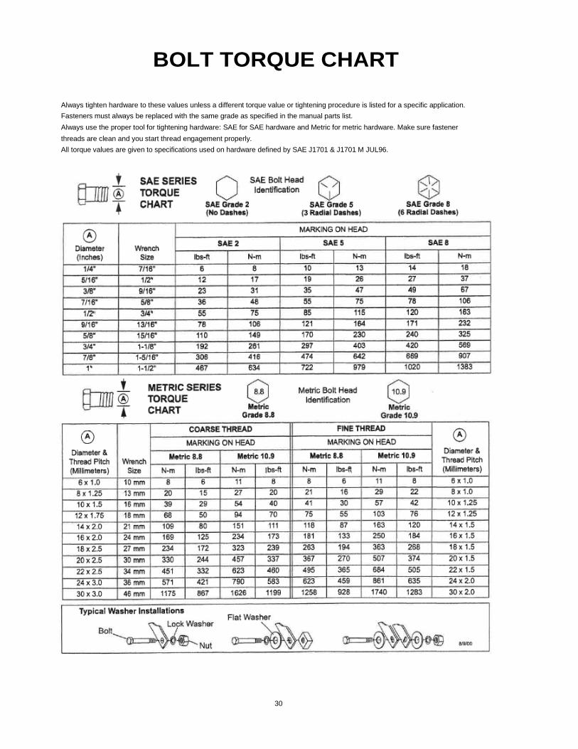
BOLT TORQUE CHART
Always tighten hardware to these values unless a different torque value or tightening procedure is listed for a specific application.
Fasteners must always be replaced with the same grade as specified in the manual parts list.
Always use the proper tool for tightening hardware: SAE for SAE hardware and Metric for metric hardware. Make sure fastener
threads are clean and you start thread engagement properly.
All torque values are given to specifications used on hardware defined by SAE J1701 & J1701 M JUL96.
30
O

NOTES

NOTES

SAFETY PRECAUTIONS MOST ACCIDENTS OCCUR BECAUSE OF NEGLECT OR CARELESSNESS.
AVOID NEEDLESS ACCIDENTS BY FOLLOWING ALL OF THE SAFETY PRECAUTIONS LISTED BELOW.
Machinery should be operated only by those who are
responsible and are authorized to do so.
Stop the engine, lower all equipment, lock the brakes, and
remove the ignition key before dismounting from the skid
steer.
Never stand between skid steer and attachment while skid
steer is being connected to the attachment.
Loose fitting clothing should not be worn, to avoid catching
on various parts.
Detach attachment in area where children normally do not
play.
When performing adjustments or maintenance on an
attachment, first lower it to the ground or block it securely at
a workable height.
Only a qualified operator should be permitted on skid steer
when in operation; no riders allowed.
Make certain everyone is in the clear before starting tractor
or raising or lowering equipment.
Operate the skid steer and attachment only while seated in
the driver's seat.
Reduce speed when transporting mounted attachments to
avoid bouncing and momentary loss of steering control.
A heavy load can cause instability of the skid steer. Use
extreme care during road travel. Slow down on turns and
watch out for bumps. Skid steer may need front counter-
weights to counter-balance the weight of the attachment.
Reduce speed on hillsides or curves so there is no danger
of tipping.
Avoid driving too close to the edge of ditches or drop ofts.
Do not transport implement on public roads without
reflectors and slow moving vehicle emblem in daylight and
with approved warning lights at night and other periods of
poor visibility.
Keep work area clear of all debris. Never assume an area
is clear. ALWAYS CHECK.
Check to make certain there are no buried utilities in the
work area before starting work.
Keep alert and watch the front as well as the rear when
working with the attachment.
SPARTAN EQUIPMENT Joppa, MD 21085 1-888-888-1085
WEB: http://www.SpartanEquipment.com
E-MAIL: [email protected]
