optimum efi installation guide - affordable fuel injection
TRANSCRIPT

1
OPTIMUM EFI
AFFORDABLE FUEL INJECTION INC.
1775 N. Lapeer Rd. Unit B Oxford, MI 48371
248-393-1621
2
TABLE OF CONTENTS
1. Kit Contents……………………………………………………….…..….3
2. Installation Instructions…………………………….………….……4
3. Component Description……………………………..…….………..9
4. Final Checks……………………………………………………..………..12
5. Installation tips (helpful installation pictures)…………..13
6. Component Parts and Part Numbers………………………….17
7. Troubleshooting……………………………………………..………....18
8. Diagnostic Trouble Codes………………………………..…………33
9. ECM Pin Out and Wire Coding…………………………………….36

3
Congratulations on the purchase of your Affordable Fuel Injection™ “OPTIMUM
EFI”® TBI system. We are confident that this purchase will give you the performance and driveability you deserve from your vehicle. The following
instructions are intended to provide you with thorough description for installing your TBI system. If you do not understand any part of the instructions, need clarification or simply need more information, please e-mail us at:
[email protected]. Please read through the instructions completely before beginning your installation. Many of your questions may be
covered within this manual. Verify that all of the components are included in your shipment.
1. Wiring Harness 2. ECM
3. Throttle Body (with IAC and TPS) 4. ECT sensor (Engine Coolant Temp)
5. IAT sensor (Intake Air Temp) 6. MAP Sensor (Manifold Absolute Pressure)
7. Wide Band O2 Sensor with exhaust ring for installation
8. Fuel Pump Relay 9. Power Relay
10. Check Engine Light 11. Distributor (option)
12. Distributor module (option)
13. Fuse protection link 14. Fuel filter
15. Inline Fuel Pump 16. Fuel Pressure regulator
17. Electric Fan Relay (optional)
INSTALLATION INSTRUCTIONS

4
NOTE: THIS IS A CUSTOM FUEL INJECTION SYSTEM BUILT FOR YOUR
ENGINE. AS WITH ALL CUSTOM PROJECTS SOME FABRICATION MAY
BE REQUIRED. YOU MAY ALSO REQUIRE SOME SMALL PARTS THAT
ARE NOT INCLUDED IN THE KIT.
ECM The ECM is the central unit of the fuel injection system. This unit provides the
signals that trigger the injectors. The ECM can be
mounted anywhere in the engine compartment. Typically it is mounted somewhere behind the engine but is not
required. This is a state of the art ECM which is weatherproof,
shockproof and can be operated at a continuous temperature of 230o F.
WIRING HARNESS
The wiring harness included with this kit has been specially built for your unique application. This harness only includes the connectors and leads that
are required to run your particular engine based upon the order specifications.
Therefore, if there are leftover parts this indicates that an error has been made during assembly and installation of the system. (Open Loop
configurations may still have the O2 sensor connector, but not used) Each connector will be marked with a label to the correct sensor that it is to be
connected too. In the following section we will describe each sensor and
the connector that attaches to it. The wiring harness is fabricated to allow the
proper sensor to be hooked up to the respective connector. The “keying” of the connector will not allow for an improper connection.
There is one fusible link required which is to be securely connected to the red battery wire after this wire is cut to length.
The PINK power wire needs to be attached to an Ignition 1 (IGN1,
battery power only with key on or in the crank position) power source. Ensure that this is an ignition 1 source. An ignition 1 source is 12volts available any time that the key is not in the off position. Also, this PINK
wire must have 12V while the vehicle is in the cranking mode (starting). This means the wire will have power when the key is on, or
start, or back to on. Usually this wire can be taken from the proper terminal on the ignition switch, the power side of the coil (+), or from
the fuse box. The system will not work if power is not provided to the (PINK) ignition wire while cranking. On some early vehicles, the only option is the wire which powers/powered the coil.
The red wire is to be connected to a direct battery lead which has 12v
always feeding it; a direct connection to the battery or starter relay is

5
optimal. It is important that these wires are connected to the indicated source or your fuel injection system will not operate properly.
A main fuse link is provided which is the main fuse protection for the
entire system. This link is to be installed at the battery source and secured and sealed to the red battery wire.
It is very important that the ECM and components be supplied with proper voltage. Improper operation of the charging system
can result in system malfunctions and drivability issues. The vehicles charging system must be operating at 13.2 volts or more at all times, especially at idle.
Included are two relays, a power relay and fuel pump relay(on return fuel
systems). These relays are of the same design and can be used for either application. The power relay is used to ensure proper voltage is supplied to your system so as not to tax the current wiring of the vehicle with undue
voltage requirements. The power relay is controlled by the ECM and connects to the battery feed. Operation of the power relay is controlled by the ECM and
is the power feed for all of the battery and switched power feeds in the harness such as the injector(s) This battery lead is labeled and can be attached directly
to the battery, the starter solenoid, or any other appropriate full time 12-volt supply. We have included a length of wire long enough to choose your own connection option. Insure that the main fuse circuit protection is installed
between the battery power source and the red battery wire. A low temperature solder connector is also provided to provide a secure and sealed connection.
The fuel pump relay is controlled by the ECM and no connections are required except for the power wire to the fuel pump itself.
An ALDL connector is another extension of the harness which is located in your wiring harness. This connector is an OBDII connector and allows the use of a
C.A.N. based OBDII scan tool to read operational data of the unit as well as read and clear diagnostic codes.
A white (or orange) wire is also provided which connects to a check engine light. This light can be mounted in the dash, use an empty “idiot light” socket
in the instrument panel, or mounted in a small bracket under the dash. It should be mounted in an area noticeable in case of any malfunctions. The wire from the ECM is the ground for the light. When a fault exists, or the system
is in diagnostic mode, or the engine is not running with the key on, the light is illuminated. The other side of the light requires a 12v ignition feed. If the CEL
supplied is an LED, the light may illuminate slightly under normal conditions. Installing a 2000 ohm resistor in between the two wires of the CEL will keep the light from a dull illumination.
Several black wires with an eyelet on the end are to be bolted to an appropriate
engine ground. Insure that you have cleaned the surface where this wire will mate to. Empty threaded holes in the intake manifold or cylinder head have

6
been good locations for this wire. Two star washers have been provided to insure a good continuity to ground.
It is advisable to run a separate ground wire from the battery to the frame of
the vehicle. It is also advisable to run another ground wire from the location of the ground wire from the harness to the frame at the same mounting location as the wire from the battery.
THROTTLE BODY
Two Barrel Throttle Body Your AFI throttle body is a direct replacement for your carburetor. There are many different possible configurations to connect your throttle lever.
AFI does not supply or have any recommendations on throttle cables. Many users modify production cables and brackets for proper fitment. Lokar is an
aftermarket company with many options for throttle cables and brackets. Ensure that smooth unrestricted movement can be obtained from the accelerator pedal from idle to WOT (Wide Open Throttle). Connect the wires to
the injector, TPS (Throttle Position Sensor), and IAC (Idle Air Control) valve.
Connect the fuel line to the backside of the throttle body. This is an AN type or barbed pipe
thread fitting and is sufficient for the pressures encountered with the fuel injection system.
Four Barrell Throttle Body
Your Optimum Marine AFI system may have been ordered with a 4 bbl. throttle body.
The 4 bbl. installation is slightly different than the 2 bbl. units. A 4 bbl. TBI unit will look much like a 4 bbl. carburetor you may
have seen with the injectors underneath what would normally be a fuel bowl. These
units are true 4 bbl. as they work off the front two barrel’s/injectors and bring the rear two injectors in as the secondary
throttle plates open.
Four-barrel intakes typically come in one of two bolt patterns: Squarebore and Spreadbore. Squarebore is typically Holley, Motorcraft and some other aftermarket brands. Spreadbore is typically Q-Jet, Thermoquad and some
aftermarket brands as well. If your unit is a spreadbore you will be supplied with an adapter to go from Spreadbore to Squarebore as the throttle body is
a squarebore base.

7
Fuel feed for the 4 bbl. is different than the 2 bbl. On your 4 bbl. throttle body will be a fuel feed manifold, an exit fitting and a plug. The fuel feed
manifold will be mounted on the TPS side of the throttle body. This unit may be set up to incorporate the fuel entry at the
front of the back of the feed manifold. The remaining two pieces can also be installed in either of the remaining two fuel holes
adjacent to the fuel feed. The exit fitting is used to return the fuel back through the
pressure regulator. From the pressure regulator the fuel pressure is regulated, and the unused regulated fuel is returned to the
fuel tank. The fuel plug is exactly as described, it is a plug for the 4th fuel port on
the throttle body. When installing the fuel manifold to the
throttle body, loosen up the two fittings which are part of the hose between the two
tubes running up to the fuel inlet ports. Screw in and tighten the two tubes feeding
the fuel ports and when tightened, go back and tighten up the two fittings which are part of the hose which you previously
loosened up.
FUEL PUMP An external inline fuel pump has been included with your TBI system. This
pump delivers a variable fuel pressure to the throttle body through the fuel pressure regulator (for return systems). This regulator regulates the fuel
pressure between 42 – 55 psi and back to the fuel tank. Engine applications less than 5.0L in most cases use a 35 – 45 psi regulator. This pump should be
mounted to the frame of your vehicle. If necessary weatherproof the pump by mounting a cover over it.
A fuel filter is to be installed in the fuel line PRIOR to the fuel pump. Premature failure of the pump can be the result of improper fuel filter
installation. Some aftermarket high density fuel filters can cause a large drop in fuel pressure under load and are not recommended for use with your system. If you are using high density filters insure that you have proper fuel
pressure during all modes of operation. It is not necessary to use a fuel filter before and after the fuel pump. Some people however feel more comfortable
with this type of setup and it can be incorporated. Insure if you do this that the lowest micron rated filter is after the pump.
A 12 or 16 Ga. pink wire labeled “Fuel Pump”, with sufficient length has been included with the wiring harness for the pump power feed. This wire comes
8
from the fuel pump relay which can be mounted in a convenient under hood location. It may be desirable to enclose these relays in a plastic box or provide
suitable protection from any elements. The mounting and the ground are very
important for proper operation of the fuel pump. A ground wire is to be attached to a stable clean body ground or run back to a battery ground
(Return Fuel System). An improper ground will result in insufficient fuel flow
and/or premature pump failure. Mount the fuel pump in the bracket supplied or similar, to keep the pump noise from radiating into the vehicle. You may
want to “prime” the fuel feed line with gasoline to aid in the priming of the pump for proper operation.
FUEL LINES & PRESSURE REGULATOR
NOTE: Only use fuel line rated for fuel injection. Steel line or braided fuel line is the most desirable for this application.
ERFS – Electronic Returnless Fuel Supply ERFS is an option that can be incorporated into your Optimum EFI® system. This system eliminates the need for a fuel pressure regulator and is a direct
fuel line from the fuel pump to the throttle body. A PWM (Pulse Width Modulated) signal is generated by the ECM to maintain a constant fuel
pressure. A fuel pressure sensor is mounted at the throttle body which monitors the fuel pressure and the ECM controls to the preprogrammed
pressure. One drawback of ERFS is the lack of fuel flow through the fuel pump at low fuel demand for extended periods of time (idle in traffic). For this reason it is
necessary to install a small bleed (included) to allow a small amount of fuel to bleed back to the fuel tank. Technically this then is not returnless but is
required to keep the fuel pump from overheating. The ideal application for the ERFS system is an intank fuel pump since the bleed can be installed post pump and bleeds into the fuel tank. Since no one
can anticipate that this condition would never exist, it is necessary.
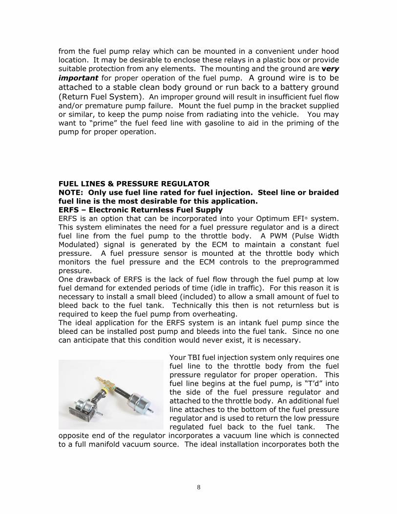
Your TBI fuel injection system only requires one fuel line to the throttle body from the fuel pressure regulator for proper operation. This
fuel line begins at the fuel pump, is “T’d” into the side of the fuel pressure regulator and
attached to the throttle body. An additional fuel line attaches to the bottom of the fuel pressure regulator and is used to return the low pressure
regulated fuel back to the fuel tank. The opposite end of the regulator incorporates a vacuum line which is connected
to a full manifold vacuum source. The ideal installation incorporates both the

9
fuel feed and return lines attached to the fuel tank. When this style regulator is used with a 4 bbl. throttle body, the regulator is post throttle body and not
pre throttle body. In this case one of the hose fittings needs to be removed and plugged allowing the fuel to
be pressurized through the throttle body to the regulator. On the end of the regulator is
the return and opposite that end a vacuum line is attached
which varies the fuel pressure, the same as the 2 bbl. application.
Some fuel tanks are supplied with a tank vent for evaporative
emission purposes. These fittings usually have a restriction incorporated internally and are not sufficient for a fuel return. If the restriction can be removed and the fitting is of sufficient
size, this can be used for a return. Do not eliminate this fitting for evaporative emissions purposes if these items are still in use. Insure that any factory
fittings (if used) that are on the fuel tank are free flowing and do not restrict the flow of fuel back to the fuel tank.
ENGINE SENSORS
MAP SENSOR The MAP sensor is a very important part of the fuel injection system. This sensor sends a voltage to the ECM in relation to the amount of vacuum
(pressure) the engine is creating. This signal is used in conjunction with the engine speed to infer the amount of air that is being used by the engine. This
is what is called a speed/density system. Because fuel control is very dependent upon this signal it is very important to install correctly. This sensor is to be installed as close to the
manifold vacuum source as possible. The port on the
sensor is to face down with the vacuum line attached. This vacuum line should have no sags or dips and the
length should be as short as possible. Some people install this sensor in
the center of the firewall towards the cowl or even under the air cleaner at times. Attention needs to be given to the connection of the vacuum line
ensuring no leaks. If using the optional carb. heat adapter, there is an extra tapped hole which is the ideal location for the MAP sensor source.
COOLANT SENSOR The coolant sensor is just like it sounds; it sends an electrical signal to the ECM
in proportion to the engine coolant temperature. This sensor is to be installed before the thermostat preferably or in the block itself. (See picture next section) There is a plug in the rear of the block that can be used for the ECT
10
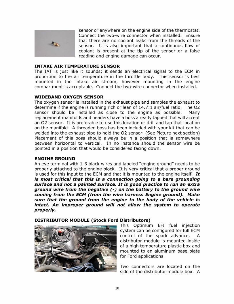
sensor or anywhere on the engine side of the thermostat. Connect the two-wire connector when installed. Ensure
that there are no coolant leaks from the threads of the sensor. It is also important that a continuous flow of
coolant is present at the tip of the sensor or a false reading and engine damage can occur.
INTAKE AIR TEMPERATURE SENSOR The IAT is just like it sounds; it sends an electrical signal to the ECM in
proportion to the air temperature in the throttle body. This sensor is best mounted in the intake air stream, however mounting in the engine compartment is acceptable. Connect the two-wire connector when installed.
WIDEBAND OXYGEN SENSOR
The oxygen sensor is installed in the exhaust pipe and samples the exhaust to determine if the engine is running rich or lean of 14.7:1 air/fuel ratio. The O2 sensor should be installed as close to the engine as possible. Many
replacement manifolds and headers have a boss already tapped that will accept an O2 sensor. It is preferable to use this location or drill and tap that location
on the manifold. A threaded boss has been included with your kit that can be welded into the exhaust pipe to hold the O2 sensor. (See Picture next section)
Placement of this boss should always be in a position that is somewhere between horizontal to vertical. In no instance should the sensor wire be pointed in a position that would be considered facing down.
ENGINE GROUND
An eye terminal with 1-3 black wires and labeled “engine ground” needs to be properly attached to the engine block. It is very critical that a proper ground is used for this input to the ECM and that it is mounted to the engine itself. It
is most critical that this is a connection going to a bare grounding surface and not a painted surface. It is good practice to run an extra
ground wire from the negative (-) on the battery to the ground wire coming from the ECM (from the wire harness Engine ground). Make sure that the ground from the engine to the body of the vehicle is
intact. An improper ground will not allow the system to operate properly.
DISTRIBUTOR MODULE (Stock Ford Distributors)
This Optimum EFI fuel injection
system can be configured for full ECM control of the spark advance. A
distributor module is mounted inside of a high temperature plastic box and mounted to an aluminum base plate
for Ford applications.
Two connectors are located on the side of the distributor module box. A

11
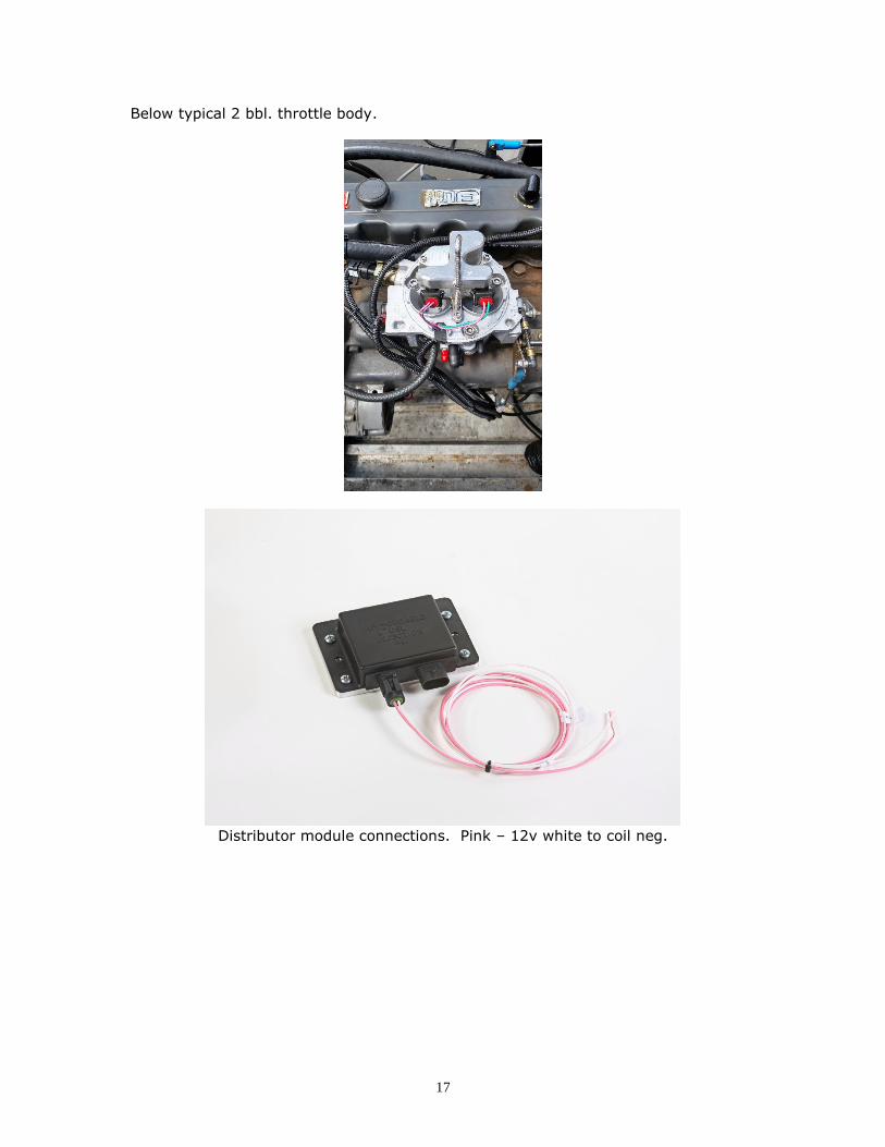
4 pin connector from the wiring harness will attach to the appropriate place on the module. An additional 2 pin connector is included with your kit and is the
power supply and trigger for the ignition coil. The pink wire labeled 12v ign. will connect to a 12 volt ign. 1 source as described above. The white wire will
connect to the negative terminal of the coil. (See Picture next section). The coil still requires a 12 volt connection to the “+” side of the ignition coil. NOTE: Ignition Coil negative “-“ is not a ground. Do not supply a ground to
this terminal, grounding this terminal will result in no spark and may overheat and burn up your coil.
DISTRBUTOR (Optional) RPM Input AFI’s Optimum EFI system can be one of several different distributors. The
ideal distributor option is the DUI (Davis Unified Ignition) HEI unit which has been built with a 7 pin module for fuel injection. These are very good
distributors but can be a little out of some budgets to be comfortable. A modified HEI distributor is the next best which is a standard aftermarket HEI style distributor which has been modified by AFI to work with your fuel injection
system. Chevrolet motors can be controlled with either a small cap EFI distributor or a large cap HEI style.
Ford V-8 5.0L and 5.8L blocks will use a stock Ford Hall Effect distributor with an external ignition module for this particular application. If your kit is of this
type, it has been tested as sufficient at AFI. If you have updated to an MSD or similar module, or did not order ECM spark
control, a white wire labeled coil “-“ or tach will connect to the tach output of the MSD or the negative terminal of the coil.
Insure that after your new distributor has been installed that the appropriate timing mark is used to set the initial ignition timing. Bring #1 cylinder up to
TDC on the compression stroke with the spark plug removed and verify the timing you will use is lined up with this mark. Some engines that have been
updated can have two different timing mark locations. If not properly set the engine will not operate correctly. Set the timing to 20 deg. BTDC once the engine is started and fully warmed up or what the value broadcast for spark
advance is reading on your scan tool

12
FINAL CHECKS AND START UP
After you have finished the above installations you are ready to check the system for operation. Turn the ignition key to the “ON” position, but do not
start the engine. The fuel pump should turn on for about 2 seconds and then turn off. If this does not happen see #7 below in troubleshooting. . Disconnect the connector from the injector and crank the engine for about 5
seconds; reinstall the injector connector after this operation Leave the ignition in the ”ON” position until the fuel pump has turned off. Turn the ignition off
for at least 10 seconds and repeat the ignition cycle. Perform this operation 2 or 3 times to allow fuel to fill the system preparing to start. Inspect all fuel lines and connections to ensure there are no fuel leaks. It would also be
appropriate at this time to install a fuel pressure gauge to insure that the proper fuel pressure of 42 -55 (or 35 – 45 in smaller displacement engine
applications)psi is being delivered. Assuming no fuel leaks, you are ready to start the engine. Do not press on
the accelerator pedal to start the engine. The IAC valve will provide the proper amount of air for the vehicle to start and run. Start the engine and let it idle;
it may take a bit to run smoothly. At this point the control system has not “learned” the engine and the IAC valve has not learned its proper position.
These are all functions of the fuel injection system that happen after the engine has been running. It may be necessary to adjust the ignition timing close to the final setting of 20 deg. BTDC or the broadcasted value from you scan tool.
Restart the engine and let it idle for a while. Insure that there are no fuel or
vacuum leaks while running and that the idle appears to be controlled by the ECM. The engine speed will be higher while cold and first started and will come down to a base idle on its own. If the engine will not idle properly check for
vacuum leaks, proper timing setting, or a check engine light illuminated. When all of these checks have been made, block off the air going to the IAC valve
and set the base engine speed to 750 RPM in neutral or park. When you are confident that all is running properly, you may shut it down and complete the remainder of the installation.
Set ignition timing to 20 deg. BTDC (or the value broadcast on your scan
tool)with the engine fully warmed up and at 800 RPM or less. Insure that the timing is in fact being set with the proper TDC indicator. We have found on some engines that two different indicators are present and that the timing was
set to the incorrect indicator. This causes operational issues with the engine if the timing is not set correctly.
Secure any wires that you may choose, ensuring they are routed away from exhaust manifolds, cables, etc.
Install the air cleaner and you should be ready for operation. If not completed in the earlier steps of installing the throttle body, the bar from the carburetor

13
needs to be mounted to the top of the throttle body or air cleaner stud needs to be installed to hold down the air cleaner.
A final check with a scan tool should be performed. Your OBDII enabled scan
tool can be used in Generic OBDII mode to access the sensor data. Your sensors fully warmed up should read close to the following values.
ECT > 180 IAT ambient temperature to 40 deg. or so above ambient.
MAP 8 – 13 in. / 16 – 21 in. HG. TPS 0% .5 - .7 volts Closed loop operation
Idle speed 700 – 800 RPM neutral or park STFT dither about 0% at part throttle in closed loop
LTFT 0 to + or – 15% idle at times is offset more. Call tech support for any further questions or clarification.
Once you have installed your Affordable Fuel Injection Optimum EFI system you will enjoy the modern technology of fuel injection for years to come. You
will benefit from a low maintenance system that provides good drivability and adjusts for towing, altitude and other normal drive situations. The greatest
advantage to EFI is dependability and drivability. EFI for the most part is relatively maintenance free once installed and working properly. The sensors are robust and provide for many hours of maintenance free operation. EFI also
provides seamless drivability. The system supports all of your engine functions whether it is –20 deg. Or 100 deg, at sea level or 5,000 ft.
Thank you from Affordable Fuel Injection.
FINAL INSTALLATION QUICK CHECK LIST 1. Pink ignition wire connected to 12 volts during run and crank 2. Check Engine Light connected to 12 volts not ground 3. MAP sensor is installed with port down and to full manifold
vacuum source. 4. All fuel lines are tight and no fuel leaks are present.
5. Distributor wires correctly terminated. 6. Thermostat is 190-195 deg. and operational. 7. Extra grounds supplied to the frame and the block.
8. Insure no oil leaks from oil pressure sending unit (if equipped) 9. Timing set to 20 deg. BTDC or value broadcast to the Scan Tool.
10. Idle speed in neutral is between 700-800 RPM. 11. TPS is operating between .5 - .7 volts at closed throttle.

14
Fuel pump and fuel pressure regulator set up
Preferred MAP sensor orientation

15
Typical O2 installation when tapped hole is not available in the exhaust manifold. An
18mm hole can be drilled and tapped into the standard O2 location in the exhaust
manifold.
O2 sensor installation

16
Above – typical ports on two bbl. TBI unit.
17
Below typical 2 bbl. throttle body.
Distributor module connections. Pink – 12v white to coil neg.
18
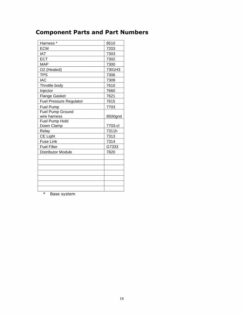
Component Parts and Part Numbers
Harness * 8510
ECM 7203
IAT 7303
ECT 7302
MAP 7300
O2 (Heated) 7301H3
TPS 7306
IAC 7309
Throttle body 7610
Injector 7660
Flange Gasket 7621
Fuel Pressure Regulator 7615
Fuel Pump 7703
Fuel Pump Ground wire harness 8500gnd
Fuel Pump Hold Down Clamp 7703-cl
Relay 7311h
CE Light 7313
Fuse Link 7314
Fuel Filter G7333
Distributor Module 7820
* Base system

19
Troubleshooting your TBI Fuel Injection
System
Quick Troubleshooting Guide
Connect Scan tool to the engine:
Verify proper value of each sensor with Key on Engine Off.
• TPS 0%
• MAP 90 – 100 dependent on altitude, will be less at high altitude.
• ECT consistent with engine temperature whether cold or warm
• IAT ambient temperature or higher
If any of the above sensors are broadcasting default values work to that problem
Default values are as follows:
• TPS 10%
• MAP 40
• IAT & ECT 77 deg. F or 25 deg. C.
If engine cranks and will not start unplug the connector from the TPS and attempt to
start. If engine starts repair TPS circuit.
If all the above checks are OK, install fuel pressure gauge.
• Turn key on and observe fuel pressure. Fuel pump should cycle on and then
off and pressure should be between 50 – 55 psi,(40 – 45 psi for smaller
displacement engines). If fuel pump does not turn on or pump does not provide
full pressure repair fuel system.
• If pump cycles off and on and does not provide pressure verify the wires are
connected properly to the fuel pump. This is for new installations or
replacement of a fuel pump. Insure the ground is connected to the negative
“-“ terminal and the power wire from the relay is connected to the positive “+”
terminal. On most AFI supplied pumps, the large terminal is the negative
terminal.
• If pump cycles on and off, determine if pump comes back on when the engine
is cranked. Fuel pump should come back on when engine is cranked.
• Verify that fuel pressure registers between 42-48 (35-40 on smaller
displacement engines)with the engine running and that the pressure rises with
a rapid movement of the throttle. Repair fuel system if pressures are not in
line or pressure drops on acceleration.
When all of these checks have been made continue to step by step guide to further
diagnose operational issues.

20
Troubleshooting guide Most of the problems encountered while installing your fuel injection system or after a
time of operation are very simple. If your check engine light is on you more than likely
have a hard fault meaning something is grounded out, unplugged, operating out of
range or has gone bad. See below for how to determine what the fault may be and
code definitions.
With the addition of Fuel Injection to your engine it is important to remember that the
basics are still there, necessary and have not changed. Batteries must be fully
charged, charging systems fully operational, the ignition system is fully operational
and the integrity of the engine is intact. All of these items are common to an engine
and need to be in full operational condition regardless of the fuel system that has been
added to your engine.
The ALDL connector allows for full diagnostics of your unit
If you have installed a Fuel Injection system in your vehicle and are having some initial
issues here is a quick checklist to work from to get you started.
1. Check to make sure your check engine light is not on, or that it is on with the
key on but the engine is not running.
2. Make sure that the red battery wire is connected to a battery source (It is highly
recommended that this wire is connected directly to the battery) and the pink
wire is connected to an ignition 1 source. If your ignition wire is not connected
to an ignition 1 source your ECM will not be powered while cranking the engine.
3. Check that the ground wire is securely fastened to the block and that the
interface between the block and the terminal is clean.
4. Ensure that there are NO vacuum leaks.
5. Ensure that your MAP sensor is connected to a full manifold vacuum source and
not a ported source.
6. Set the ignition timing correctly making sure that you have the engine fully
warmed up and operating less than 800 RPM’s and/or the timing matches the
spark advance being broadcast from your scan tool.
7. Ensure that you have full manifold vacuum routed to your fuel pressure
regulator and there are no vacuum leaks with this connection.
8. Check your fuel pressure to ensure that you are providing the proper pressure
to the system.
Fuel Pressure is critical for proper operation. Fuel tank must
be free from debris and fuel pressure needs to be constant and
consistent. Some aftermarket high density fuel filters can cause a large drop in fuel pressure under
load and are not recommended for use with your system. If you are using one of
these types of filters insure that you have proper fuel pressure during all modes of
operation.
99% of all issues are usually taken care of with one or more of these 8 steps of
diagnosis.
Pink Ignition wire MUST be connected to 12 volt switched
ignition that receives power during crank and key on.

21
First and foremost the engine and fuel injection system must be free of vacuum leaks.
Vacuum leaks are the leading cause of installation issues with your fuel injection
system. Check all sources of potential vacuum leaks including components not related
to the fuel injection system.
There are instances where the vacuum leak is coming from the bolts holding down the
adapter plate. In some instances, it is necessary to seal these with silicone to provide
a positive seal. If your adapter plate had a tag on it stating this, insure that the bolt
heads are filled and allowed to cure before running the engine.
Another common issue is a lack of good grounding. Many issues have been resolved
simply by making sure that the ground path is secure and clean.
Always start with clearing out Fuel Memory. This is accomplished by turning the key
on, engine off and immediately moving the throttle from 0 to WOT four times. Wait
30 seconds and verify after running that LTFT is 0%, if not the clearing did not work.
Insure with your scan tool that the TPS is working and moving between 0 – 100%.
Fuel System Checks
Fuel Pressure is critical to the operation of a fuel injection system. Always check to
insure that you have the proper fuel pressure. Fuel pressure should vary between
about 42 – 55 (35 – 45 for smaller displacement engines) PSI. At idle the fuel injection
system is typically around 42 – 45 (35-40 for smaller engines) psi. Higher pressure
than 55 (45 for smaller engines) psi indicates that there is an issue with the
installation. Many times this is due to kinked fuel lines, improper routing of the return
line and/or fuel line restrictions. (See Part 3 of Troubleshooting guide #3) Many fuel
tanks have fittings on them which are used for a fuel tank vent. These fittings are not
suitable to use as a return line because they have a restriction in them and restrict the
flow of fuel back to the tank. If you have installed your return line to a “vent” line you
will need to route the return line in a different fashion.
Fuel pressure on your Optimum EFI unit should vary between 42 – 55 (35 – 45 for
smaller engines) psi based on the amount of vacuum on the fuel pressure regulator
and stay constant under all throttle conditions. There should be an increase in
pressure from idle to WOT operation of the TBI unit. A pressure drop under this
operation indicates a restriction or issue with the fuel delivery system.
With retrofit fuel injection systems many times we are drawing fuel from gas tanks
that are many years old; hence many years have passed where contamination can
settle into the fuel tank. The electric fuel pump installed for a fuel injection system
will drawing a greater volume of fuel from your tank than your old system did. If there
are any contaminants in the tank this many times will plug up or greatly restrict the
flow of fuel to the system causing many issues.
Step by Step Troubleshooting guide.
Your fuel injection system has been pre calibrated to your particular vehicle. As long
as the information about your engine was correctly stated, the system as received will
provide many years of trouble free use. However from time to time problems are
encountered with your fuel injection system. Here are a few commonly asked

22
questions about fuel injection problems. Match the issue # with the chart below for
an explanation of the issue and use the troubleshooting fault tree.
Use of this section may require a digital voltmeter, test light, fuel pressure gauge,
timing light, tachometer and a diagnostic scan tool. If you are familiar with vehicles
and how they are serviced you should be able to work through this section with no
issues. In many instances you may want to have a professional automotive technician
familiar with fuel injection repair to help you.
1. My engine cranks but will not start.
2. My engine is running to lean, or is backfiring on acceleration.
3. My engine is running rich.
4. I do not seem to have as much power as I should.
5. I am getting a sag when I accelerate.
6. My engine takes longer to start than I think it should.
7. The fuel pump is not coming on when I first turn the key on.
8. The RPM on my engine does not come down when I come to an idle.
9. I am not getting as good of fuel economy as I think I should.
10. The engine is revving up and down when I come down to an idle. There
is a large “sucking” sound coming from the throttle body when it is
warmed up. My engine stalls or almost stalls when I come down to an
idle.
11. The engine stalls coming to an idle.
12. My fuel pump is real noisy.
13. My check engine light does not come on when I turn the key on.
14. My check engine light is on when the engine is running.
15. Engine shuts down and sometimes restarts and sometimes it doesn’t.
1. Engine cranks but will not start.
There is an assumption that the battery is at a full state of charge, the fuel tank has fuel in it and that all sensors are correctly connected and there are no trouble codes in the ECM and
that the readings of the scan tool are consistent with the values listed in final checks.
1. Does the injector spray fuel when cranking the engine?
Yes – Go to step 2. No – Disconnect the TPS sensor and determine if the vehicle starts, injector sprays.
If engine starts or injector sprays, repair TPS circuit. If injector does not spray move to the next “NO” step.
No - Remove the injector connector from the injector. With a voltmeter or test light measure the voltage or validate power to the pink wire of the connector with the key on.
Yes – Pink wire has voltage, go to step 1a.
No – There is no power getting to the system. Check for proper connection to the battery, fuses are good, relays have been connected and seated properly. Correct the power
issue; if there is still no fuel spray when cranking the engine after this has been corrected go to step 1a.
1a. With the voltmeter or test light still connected crank the engine and verify voltage to
the pink wire on the injector connector. Results: “0” volts or the light goes out when cranking the engine.

23
The primary (pink) ignition wire is incorrectly connected to the vehicle. This is to be an ignition 1 (ING1) source which is power
in both the key run and crank position. Correct the connection of this wire and verify voltage to the pink wire on the injector
connector. Test again for fuel spray during crank. If the engine
still cranks, is spraying fuel, but will not start go to step 2. “Low volts, < 8” This is an indication of either a battery in a state of very
low charge, a bad battery or too much resistance in the system. -record the battery voltage while cranking at the battery.
-record the voltage at the pink wire of the injector connector while cranking the engine.
-compare these two voltages, they should be within .2 (2/10) volts
of each other. If these voltages are greater than .2 there is a bad connection or too much resistance in the wire feeding the ECM.
-Correct the issue with low voltage. If cranking voltage is above 9 volts while cranking and there is still no fuel spraying the issue is
in the fuel delivery system.
“9 volts or higher” this is normal cranking voltage. If there is no fuel spraying while cranking the issue is in the fuel delivery system or
ignition system Trouble shoot the fuel system for improper operation (See Fuel System checks at the beginning of this guide). Troubleshoot
ignition system, go to 1b.
1b. Your TBI fuel injection system fueling is “triggered” from the ignition system. It is
assumed that the coil is operational, a 12 volt ignition 1 (IGN1) source is connected to the positive terminal of the coil.
Remove plug wire and check for spark while cranking. No Spark – Repair ignition system.
Has spark – Insure wire continuity between the ECM and the distributor . If fuel
is still not spraying go to fuel system troubleshooting before replacing any components. If all wires are in tact and routed correctly and all fuel system checks are correct, replace
distributor module.
2. Perform the fuel system checks found at the beginning of this troubleshooting
Guide. If the fuel pressure and fuel system are operating as required Insure that the check engine light is on with the key on but the engine not running and there are no
stored codes. If you have installed a new distributor, removed the distributor for any reason your
ignition timing may be off too much to operate the engine properly. Disconnect the connector from the injector and set the ignition timing to its proper setting while
cranking the engine. Assumption here also is that the timing mark on the balancer is
lined up with TDC of #1 cylinder and that the distributor is seated properly and not 180 degrees off. If all of this checks OK go to step 3.
3. Measure the voltage on the throttle position sensor. If using a scan tool you can read
TPS, if not measure the voltage. To measure the throttle position voltage check between
the brown wire and the black/white striped wire on the TPS with the TPS still connected and the key on. DO NOT PUNCTURE THE WIRES to measure this voltage and only use a
digital voltmeter. Voltage can be measured by back probing the TPS connector between these wires either with a thin paper clip or appropriate tool used for this type of
measurement. Voltage should be between .5 volts and .7 volts.

24
If you have gone through all of the above procedures and the engine still will not start you will need to call tech support. When you call tech support you
will need to have the following information available.
Fuel pressure at the inlet of the TBI unit________________________________
Return line fuel pressure____________________________ Voltage measured at the battery while cranking___________
Voltage measured at the pink wire on the injector while cranking____________ Voltage measured at the TPS sensor key on engine off_____________________
Codes stored in the ECM Any information that you feel is important for diagnosing the issue at hand.
2. My engine is running to lean, or is backfiring on
acceleration.
Assumption here is that all plug wires are installed properly, the secondary ignition
system (plug wires, coil, cap and rotor) is in good operating order and the engine is
in good order.
Perform fuel system checks found at the beginning of this guide and make any
corrections as necessary.
Check initial ignition timing again.
If the timing is OK check to insure that the timing is advancing as it should with
throttle lever actuation.
If the fuel system checks performed are OK and the initial ignition timing is OK you
will need to call tech support.
If you have gone through all of the above procedures and the engine
is still running lean or is backfiring on acceleration you will need to
call tech support. In many cases the specifications of the engine are
different than what was originally discussed or assumed. When you
call tech support you will need to have the following information
available.
Fuel pressure at idle________________________________
Fuel pressure while briefly accelerating the engine to WOT_____________
Return line fuel pressure____________________________
Voltage measured at the battery while running___________
Engine operational temperature_______________________
Initial ignition timing_____________________
Timing at 2000 RPM_____________________
Any information that you feel is important for diagnosing the issue at hand.
3. Engine runs too rich. Check for vacuum leaks and insure that all vacuum leaks are corrected and sealed. If the engine
is also running at a higher than expected idle this is a good indication of a vacuum leak as well.
25
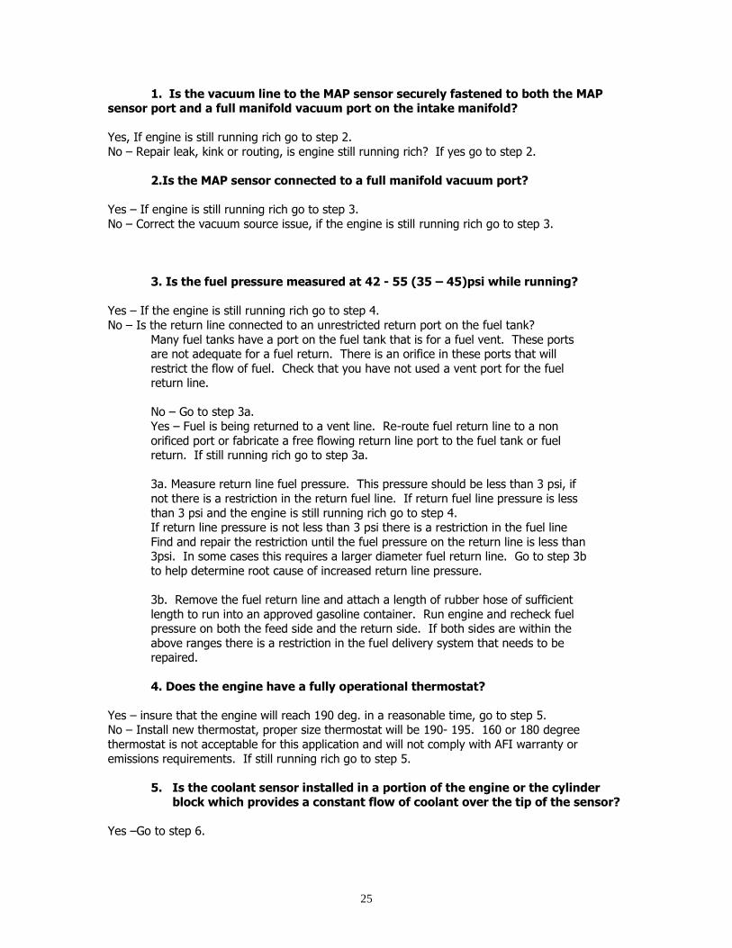
1. Is the vacuum line to the MAP sensor securely fastened to both the MAP sensor port and a full manifold vacuum port on the intake manifold?
Yes, If engine is still running rich go to step 2.
No – Repair leak, kink or routing, is engine still running rich? If yes go to step 2.
2.Is the MAP sensor connected to a full manifold vacuum port?
Yes – If engine is still running rich go to step 3.
No – Correct the vacuum source issue, if the engine is still running rich go to step 3.
3. Is the fuel pressure measured at 42 - 55 (35 – 45)psi while running?
Yes – If the engine is still running rich go to step 4.
No – Is the return line connected to an unrestricted return port on the fuel tank?
Many fuel tanks have a port on the fuel tank that is for a fuel vent. These ports are not adequate for a fuel return. There is an orifice in these ports that will
restrict the flow of fuel. Check that you have not used a vent port for the fuel return line.
No – Go to step 3a.
Yes – Fuel is being returned to a vent line. Re-route fuel return line to a non
orificed port or fabricate a free flowing return line port to the fuel tank or fuel return. If still running rich go to step 3a.
3a. Measure return line fuel pressure. This pressure should be less than 3 psi, if
not there is a restriction in the return fuel line. If return fuel line pressure is less
than 3 psi and the engine is still running rich go to step 4. If return line pressure is not less than 3 psi there is a restriction in the fuel line
Find and repair the restriction until the fuel pressure on the return line is less than 3psi. In some cases this requires a larger diameter fuel return line. Go to step 3b
to help determine root cause of increased return line pressure.
3b. Remove the fuel return line and attach a length of rubber hose of sufficient
length to run into an approved gasoline container. Run engine and recheck fuel pressure on both the feed side and the return side. If both sides are within the
above ranges there is a restriction in the fuel delivery system that needs to be repaired.
4. Does the engine have a fully operational thermostat?
Yes – insure that the engine will reach 190 deg. in a reasonable time, go to step 5. No – Install new thermostat, proper size thermostat will be 190- 195. 160 or 180 degree
thermostat is not acceptable for this application and will not comply with AFI warranty or
emissions requirements. If still running rich go to step 5.
5. Is the coolant sensor installed in a portion of the engine or the cylinder block which provides a constant flow of coolant over the tip of the sensor?
Yes –Go to step 6.

26
No – Reinstall the coolant sensor in a different location to insure constant flow of coolant over the sensor. If still running rich go to step 6.
6. Is the charging system operating properly and is the voltage measured at
the battery and the injector 13 volts or higher with the engine running?
Yes – Go to step 7.
No – Repair charging system. Note the discussion about older style AC Delco single wire alternators. If still running rich after repairing go to step 7.
7. If you have gone through all of the above procedures and the engine is still
running rich you will need to call tech support. In many cases the
specifications of the engine are different than what was originally discussed or assumed. When you call tech support you will need to have
the following information available. Fuel pressure at idle________________________________
Return line fuel pressure____________________________
Voltage measured at the battery while running___________ Voltage measured at the pink wire on the injector while cranking.
Engine RPM at start up idle on a cold start___________________________ Engine RPM at idle with stabilized temperature_______________________
Engine operational temperature_______________________ Initial ignition timing_____________________
Any information that you feel is important for diagnosing the issue at hand.
4. I do not seem to have as much power as I should.
Verify that you have set your timing properly, timing should be set to 20 deg. (or the
value being broadcast from the ECM) BTDC with the engine fully warmed up and RPM
below 800.
Verify that the timing mark for TDC of #1 cylinder that is being used to set the timing
lines up properly with TDC of #1 cylinder (#1 piston at TDC with spark plug removed).
Ensure that your plug wires are properly connected with the correct firing order.
Your fuel pressure may be insufficient; see fuel system checks at the beginning of this
guide.
Verify that there are no vacuum leaks and that the MAP sensor is properly connected.
5. I am getting a sag when I accelerate.
Insure that the MAP sensor and TPS sensor are working properly with scan tool.
Default values for MAP and TPS are a single value and can cause a sag if not operating
properly.
Timing is a critical issue with sags. Verify that your timing is correctly. see #4 also.

27
Fuel pressure is not adequate for proper operation, make sure that there is no
contamination in the tank or your fuel filter is plugged. (See Fuel System check above).
A plugged fuel filter may be an indication of a contaminated tank.
Bad ground to the block, insure that the surface that you are making the connection
to on the block is clean and making a positive connection.
Your O2 sensor may be contaminated, bad or not properly installed in the exhaust.
You may have left out some of the important specifications for the proper calibration
chip to be made.
If you have gone through all of the above procedures and the engine
is still sagging on acceleration you will need to call tech support. In
many cases the specifications of the engine are different than what
was originally discussed or assumed. When you call tech support you
will need to have the following information available.
Fuel pressure at idle________________________________
Fuel pressure when throttle is blipped to WOT ______________________
Return line fuel pressure____________________________
Voltage measured at the battery while running___________
Voltage measured at the pink wire on the injector while cranking.
Engine RPM at start up idle on a cold start___________________________
Engine RPM at idle with stabilized temperature_______________________
Engine operational temperature_______________________
Initial ignition timing_____________________
Any information that you feel is important for diagnosing the issue at hand.
6. My engine takes longer to start than I think it should.
Check for vacuum leaks, this is the most common cause.
Make sure that your timing is set correctly; see Troubleshooting point #4.
Fuel pressure is not adequate for proper operation. See Fuel System Checks at the
beginning of this guide.
Fuel pump relay is not coming on or is faulty.
Check that the MAP sensor is properly connected to a full manifold vacuum source.
Ensure that the vacuum source to your MAP sensor is free from restrictions and has a
secure connection.
Throttle plates are not adjusted properly not allowing an adequate amount of air for
starting the engine. Go to Troubleshooting guide #10 and verify the adjustment.
Throttle position sensor is out of adjustment or faulty. Throttle position voltage with
throttle fully closed with the key on should be .5 volts + .2 volts.
If you have gone through all of the above procedures and the engine
is still sagging on acceleration you will need to call tech support. In

28
many cases the specifications of the engine are different than what
was originally discussed or assumed. When you call tech support you
will need to have the following information available.
Fuel pressure at idle________________________________
Voltage measured at the battery while running___________
Voltage measured at the pink wire on the injector while cranking_____________
TPS % broadcast on scan tool key on engine not running__________________
Engine RPM at start up idle on a cold start___________________________
Engine RPM at idle with stabilized temperature_______________________
Engine RPM at idle with IAC fully blocked off.___________________
Engine operational temperature from scan tool_______________________
Initial ignition timing and idle timing_____________________
Any information that you feel is important for diagnosing the issue at hand.
7. The fuel pump is not coming on when I first turn the key on.
Is the check engine light on with the key on engine off? (Assumes check engine light
is connected properly, see installation instructions to verify check engine light
installation)
Yes - Go to step 1.
No – Check for proper installation of check engine light.
a. Check fuses to insure that they are not blown. If fuses are OK go to b.
b. Check voltage at check engine light, if 12 volt are not present the check
engine light is not connected properly. If 12 volts are present either the
ECM is not powered properly or is defective.
1. Insure that the IGN1 wire is not connected to a battery feed.
a. Check pink wire to the power relay and/or the pink wire powering up the
injector(s) to insure there is no voltage with the key off. If voltage is present
with the key off the pink wire is not properly connected or the power relay is
bad.
a. Check fuel pump relay for proper operation.
• Turn ignition off for at least 15 seconds.
• Connect an ohmmeter or test light to the blue wire at the fuel
pump relay.
• Turn ignition on, a ground signal should be present at this wire
for the first 2 or 3 seconds after turning on the ignition switch.
• If ground is not present either the ECM is not powered or
grounded properly or the ECM is faulty.
• If ground is present check for voltage at the fuel pump with the
same type of operation.
• If voltage is not present at the fuel pump check the wiring, if
wires appear to be OK replace the fuel pump relay.
• If voltage is present verify the ground for the fuel pump is
sufficient and securely fastened. If fuel pump ground is OK the
fuel pump is defective.
If you have gone through all of the above procedures and the fuel
pump is still not coming on when you turn the key on you will need to
29
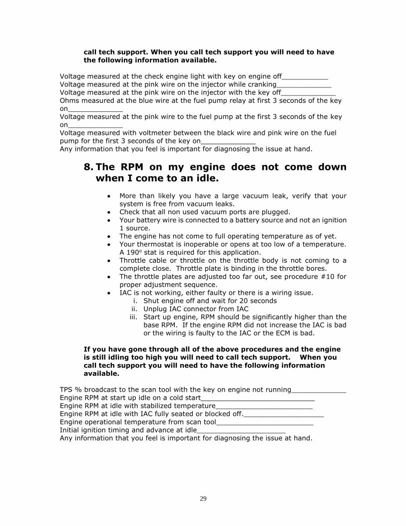
call tech support. When you call tech support you will need to have
the following information available.
Voltage measured at the check engine light with key on engine off___________
Voltage measured at the pink wire on the injector while cranking_____________
Voltage measured at the pink wire on the injector with the key off_____________
Ohms measured at the blue wire at the fuel pump relay at first 3 seconds of the key
on_____________
Voltage measured at the pink wire to the fuel pump at the first 3 seconds of the key
on_____________
Voltage measured with voltmeter between the black wire and pink wire on the fuel
pump for the first 3 seconds of the key on_____________
Any information that you feel is important for diagnosing the issue at hand.
8. The RPM on my engine does not come down when I come to an idle.
• More than likely you have a large vacuum leak, verify that your
system is free from vacuum leaks.
• Check that all non used vacuum ports are plugged.
• Your battery wire is connected to a battery source and not an ignition
1 source.
• The engine has not come to full operating temperature as of yet.
• Your thermostat is inoperable or opens at too low of a temperature.
A 190o stat is required for this application.
• Throttle cable or throttle on the throttle body is not coming to a
complete close. Throttle plate is binding in the throttle bores.
• The throttle plates are adjusted too far out, see procedure #10 for
proper adjustment sequence.
• IAC is not working, either faulty or there is a wiring issue.
i. Shut engine off and wait for 20 seconds
ii. Unplug IAC connector from IAC
iii. Start up engine, RPM should be significantly higher than the
base RPM. If the engine RPM did not increase the IAC is bad
or the wiring is faulty to the IAC or the ECM is bad.
If you have gone through all of the above procedures and the engine
is still idling too high you will need to call tech support. When you
call tech support you will need to have the following information
available.
TPS % broadcast to the scan tool with the key on engine not running_____________
Engine RPM at start up idle on a cold start___________________________
Engine RPM at idle with stabilized temperature_______________________
Engine RPM at idle with IAC fully seated or blocked off.___________________
Engine operational temperature from scan tool_______________________
Initial ignition timing and advance at idle_____________________
Any information that you feel is important for diagnosing the issue at hand.

30
9. I am not getting as good of fuel economy as I think I should.
If all is set up properly with the installation of your fuel injection system you are
probably getting as good of fuel economy as you are going to get.
1. Insure that your timing is set properly and operational
2. Your thermostat is in good working order and is 190 degree or above.
3. Your fuel pressure is at the specified pressure (see fuel system check at the
beginning of this guide.
4. You may have other factors such as tires, brake drag or other external issue
from the fuel injection system that is not working properly.
5. Re-evaluate your driving habits and insure that you are driving in a fashion
that will provide you optimum fuel economy. If you are trying to race
everyone from the light chances are you will not get the fuel economy that
you expect.
If you have gone through all of the above procedures and you still
feel that you should be getting better fuel economy you will need to
call tech support. In many cases the specifications of the engine are
different than what was originally discussed or assumed. When you
call tech support you will need to have the following information
available.
What is the Fuel Economy that you are getting______________________________
What is the Fuel Economy that you are expecting____________________________
Voltage measured at the battery while running___________
TPS % with the key on engine not running__________________
Engine RPM at idle with stabilized temperature_______________________
Engine operational temperature_______________________
Initial ignition timing and idle spark advance_____________________
Trouble Codes from the ECM (see #14)______________
Any information that you feel is important for diagnosing the issue at hand.
10. The engine is revving up and down when I come down to an idle. There is a large “sucking” sound coming from the throttle body when it is warmed up. My engine stalls or almost stalls when I come down to an idle.
• This is usually an indication of a vacuum leak; again make sure that you have
no vacuum leaks.
This could also be an indication of the wrong base ignition timing. Verify that you have
set your ignition timing correctly (see #4).
Your engine may also require more air going through the throttle plates at idle than it
is currently set for. Here is a procedure to check this setting.
a. Make sure your engine temperature is at full operating temperature.

31
b. Plug the IAC passage on the inside of the throttle body with a piece of tape
or your finger and unplug the IAC connector from the IAC.
In some cases you may need to shut the engine off and turn in (open up the
throttle plates) a couple of turns to move more air through the throttle plates
than through the IAC valve. With this method, open the plates, start the
engine and allow to operate for 1 minute or more fully warmed up. RPM should
be higher than 800 RPM. After 1 minute unplug the IAC valve.
c. Check that the RPM is 700 – 800 in neutral with the engine fully warmed up
and/or adjust as necessary, re-install the IAC connector, remove the tape if
you taped over the IAC port and turn the engine off.
d. Wait for 30 seconds with the key turned off and then restart the engine.
e. If you have a fast idle after 1 minute of operation this did not work or you
have a vacuum leak that is not repaired, or the throttle plates are already too
far open. You may have to go through the procedure again.
f. If you do not have a fast idle then it is OK and you can proceed to determine
if the plates are adjusted properly. Let the engine idle for a little bit and then
check your idle speed in drive. The speed should be about 625 in drive or 700
in neutral or park. If it is lower than this you can raise the idle up or if it is
above this determine if you should bring the speed down.
If you have gone through all of the above procedures and the engine
is still idling too high you will need to call tech support. When you
call tech support you will need to have the following information
available.
TPS % with the key on engine not running__________________
Engine RPM at start up idle on a cold start___________________________
Engine RPM at idle with stabilized temperature_______________________
Engine RPM at idle with IAC fully seated or blocked off.___________________
Engine operational temperature_______________________
Initial ignition timing, advance at idle_____________________
Any information that you feel is important for diagnosing the issue at hand.
11. The engine stalls coming to an idle.
Verify all ignition system components are operating properly, including cap, rotor,
secondary ignition wires and coil.
Verify that the IAC is operating properly.
• Shut engine off and wait for 20 seconds
• Unplug IAC connector from IAC
Start up engine, RPM should be significantly higher than the base RPM. If the engine
RPM did not increase the IAC is bad or the wiring is faulty to the IAC or the ECM is
bad. Repair as necessary.
Verify proper fuel pressure, perform above fuel system checks.
Verify timing is proper
Verify that the EGR is working properly and not sticking. (if equipped)
Sticking EGR valve will cause a stall.

32
12. My fuel pump is real noisy.
If your fuel pump is real noisy you may not have isolated it from the body or the frame
real well. Isolation brackets were provided with your fuel pump. If these are properly
installed it should isolate any radiated noise from the pump. If this is insufficient you
may need to isolate it more with some rubber grommets.
We have also diagnosed noisy fuel pumps with fuel return lines being too small. By
stepping up the size of the return line you may eliminate fuel pump noise after the
other items have been addressed. Fuel pump noise also can radiate through the fuel
lines to the frame or body of the vehicle. Insure that the fuel lines are isolated as well
if need be to eliminate the noise.
A noisy fuel pump can also be an indication that it is starving for fuel. Insure that all
filters are in good order and that the fuel tank sock is clean. Prolonged fuel starvation
will damage the fuel pump and not allow proper flow; it may also radiate a lot of noise.
13. My check engine light does not come on when I turn the key on.
Your check engine light should illuminate when you turn the key to the on position for
a bulb check.
Check for proper installation of check engine light.
a. Check fuses to insure that they are not blown. If fuses are OK go to b.
b. Check voltage at check engine light, if 12 volt are not present the check
engine light is not connected properly. If 12 volts are present either the
ECM is not powered properly or is defective.
c. If the fuse is OK insure that you are receiving 12 volts to the ECM where
indicated (see wiring diagram provided) If you are not receiving 12 volts
to the ECM something in the vehicle’s power circuit is not connected
properly.
d. If 12 volts is available at the proper cavities of the ECM please check
that you have a proper ground circuit to the engine block.
If you have gone through all of the above procedures and the fuel
pump is still not coming on when you turn the key on you will need to
call tech support. When you call tech support you will need to have
the following information available.
Voltage measured at the check engine light with key on engine off___________
Voltage measured at the pink wire on the injector while cranking_____________
Voltage measured at the pink wire on the injector with the key off_____________
Any information that you feel is important for diagnosing the issue at hand.
14. My check engine light is on when the engine is running.
A check engine light indicates a hard fault with your fuel injection system.

33
Insure that all of your sensors are connected, you have a good ground and that no
wires are pinched.
Also insure no vacuum leaks and that your MAP sensor is connected to a full manifold
vacuum source.
If all of these steps indicate a proper installation and no issues you will need to read
the codes from the memory area of the ECM and follow the diagnostic procedures for
that particular code.
Your AFI fuel injection system is equipped with the latest OBDII level software to
retrieve trouble codes. Using any OBDII CAN protocol scan tool you can display the
trouble codes. If you have the service software for your ECM this is very easy as well.
Simply connect the laptop and any trouble faults will be listed under trouble faults.
An OBDII connector is provided that will plug into the CAN (ALDL) connector in your
harness. This connector is not supplied with every kit but to every location. Larger
locations will have several connectors based on the # of Scan tools available to the
location. These connectors should be kept with the scan tool. The ALDL connector
(ALDL) should be kept sealed with the appropriate connector at all time the vehicle is
in operation and not using the diagnostic tools.
15. Engine shuts down and sometimes restarts and sometimes it doesn’t.
Your Optimum EFI system can be equipped with integrated automatic shutdown
features. Some are standard and others are optional. Each shut down will set a DTC
and store the code in the ECM. Insure that you clear any code after diagnosing that
your issue was an automatic shut down feature.
The shut down features are as follows:
High engine coolant shut down. (If turned on)
The ECM will cause the engine to shut down if the temperature reaches 238
deg F. It will not run until the temperature is below 234 deg F.
• A code P0217 will set under this condition.
• Insure that you clear the code if this code has been present.
• This same condition will be present if the ECT is defective.
• If your vehicle is continually setting this code and/or shutting down,
determine the cooling system issues which are causing it and repair
accordingly.
• Engines need to be equipped with the proper size radiator, fan and a fan
shroud to provide proper cooling.

34
TROUBLE CODES
All trouble codes are standard OBDII level and values.
OBDII Code OBDII Desc.
P0106 MAP Range Performance Problem-Sticking
P0107 MAP Circuit Low Input
P0108 MAP Circuit High Input
P0111 IAT Range Performance Problem
P0112 IAT Circuit Low Input
P0113 IAT Circuit High Input
P0115 ECT Range Performance Problem
P0117 ECT Circuit Low Input
P0118 ECT Circuit High Input
P0122 TPS Circuit Low Input
P0123 TPS Circuit High Input
P0130 O2 Sensor Circuit malfunction
P0131 O2 Sensor Low Voltage
P0132 O2 Sensor High Voltage
P0171 Fuel Trim Lean - At adaptive maximum
P0172 Fuel Trim Rich - At adaptive maximum
P0200 Injector Circuit Malfunction
P0217 Engine Over Temp Condition
P0219 Engine Overspeed Condition
P0230 Fuel Pump Circuit Malfunction
P0322 EST Circuit Open
P0460 Fuel Level Circuit Malfunction
P0462 Fuel Level Circuit Low
P0463 Fuel Level Circuit High
P0521 Engine Oil Pressure Low
P0522 Oil Pressure Circuit Low
P0523 Oil Pressure Circuit High
P0562 System Voltage Low
P0563 System Voltage High
P0650 MIL circuit malfuction
P1102 MAP In-Range Indicates Low
P1103 MAP In-Range Indicates High
P1121 TPS Adapt Low Min
P1122 TPS Adapt Low Max
P1123 TPS Adapt High Min
35
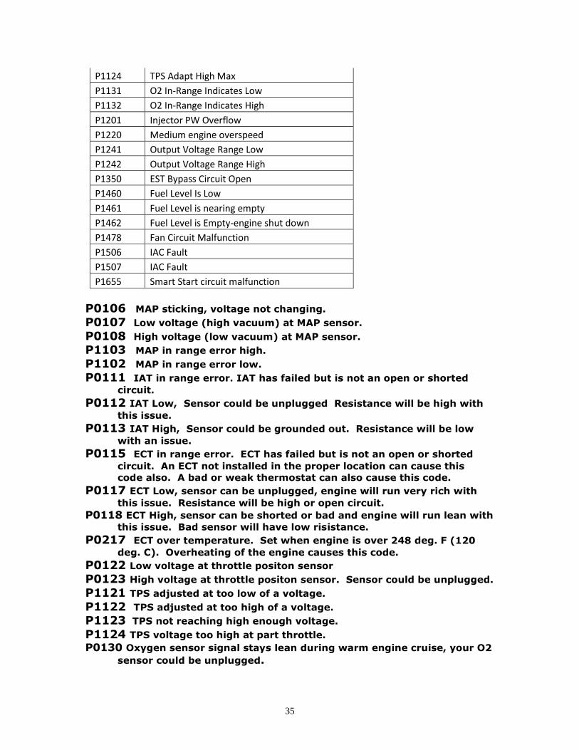
P1124 TPS Adapt High Max
P1131 O2 In-Range Indicates Low
P1132 O2 In-Range Indicates High
P1201 Injector PW Overflow
P1220 Medium engine overspeed
P1241 Output Voltage Range Low
P1242 Output Voltage Range High
P1350 EST Bypass Circuit Open
P1460 Fuel Level Is Low
P1461 Fuel Level is nearing empty
P1462 Fuel Level is Empty-engine shut down
P1478 Fan Circuit Malfunction
P1506 IAC Fault
P1507 IAC Fault
P1655 Smart Start circuit malfunction
P0106 MAP sticking, voltage not changing.
P0107 Low voltage (high vacuum) at MAP sensor.
P0108 High voltage (low vacuum) at MAP sensor. P1103 MAP in range error high.
P1102 MAP in range error low.
P0111 IAT in range error. IAT has failed but is not an open or shorted
circuit.
P0112 IAT Low, Sensor could be unplugged Resistance will be high with
this issue. P0113 IAT High, Sensor could be grounded out. Resistance will be low
with an issue.
P0115 ECT in range error. ECT has failed but is not an open or shorted
circuit. An ECT not installed in the proper location can cause this
code also. A bad or weak thermostat can also cause this code.
P0117 ECT Low, sensor can be unplugged, engine will run very rich with
this issue. Resistance will be high or open circuit.
P0118 ECT High, sensor can be shorted or bad and engine will run lean with
this issue. Bad sensor will have low risistance.
P0217 ECT over temperature. Set when engine is over 248 deg. F (120
deg. C). Overheating of the engine causes this code.
P0122 Low voltage at throttle positon sensor P0123 High voltage at throttle positon sensor. Sensor could be unplugged.
P1121 TPS adjusted at too low of a voltage.
P1122 TPS adjusted at too high of a voltage.
P1123 TPS not reaching high enough voltage.
P1124 TPS voltage too high at part throttle.
P0130 Oxygen sensor signal stays lean during warm engine cruise, your O2
sensor could be unplugged.

36
P0131 O2 sensor failed lean (low voltage)
P0132 O2 sensor failed rich (high voltage)
P1131 O2 sensor lean, does not mean sensor is bad, can set with large
vacuum leak, low fuel pressure or other event causing a lean
condition. Contaminated sensor can cause this code.
P1132 O2 sensor rich, does not mean sensor is bad, can set with
contaminated sensor, too high of fuel pressure or any event causing a
rich condition.
P0172 Internal fuel memory is at its rich limit P0171 Internal fuel memory is at its lean limit
P0200 Injector or injector circuit fault P1201 Injector PW overflow
P0230 Low voltage at fuel pump or Low voltage at Fuel pump relay
P0322 Low voltage at electronic spark timing circuit
P1350 Fault at electronic spark timing bypass circuit
P0460 Fuel level circuit malfunction
P0462 Fuel level circuit low
P0463 Fuel level circuit high
P1460 Fuel level is low, low fuel light is on
P1461 Fuel level is at a critical level, low fuel light is flashing
P1462 Engine has shut down due to low fuel level, low fuel light is
Flashing
P0521 Oil pressure low, engine will shut down after a short start up or will
shut down if the engine loses oil pressure.
P0522 Oil pressure circuit low
P0523 Oil pressure circuit high
P0563 High voltage at battery P0562 Low voltage at battery
P0650 MIL circuit malfunction
P1241 Sensor voltage is Low
P1242 Sensor voltage is High
P1506 IAC circuit error
P1507 IAC circuit error
P0219 Engine has been operated at the rev. limiter
P1220 Medium engine over speed
P1655 Smart Start circuit malfunction

37
ECM Connector Pin Out and Wire Coding
Connector A Connector B Pin # Wire Color Connect to:
Pin # Wire Color Connect to:
1 Green IAC - B 1 Blk/Wht Sensor Gnd
2 Blue IAC - A 4 Tan Ign, Crank
4 Yellow Low Fuel Light 5 Orange Dist. A
5 Green Injector 7 Blue Oil Pressure - C
7 White EGR Solenoid 8 Pink Ign. 12v
8 Yellow Smart Start Relay 12 Yellow ECT
9 Clear or Red Dist Mod D 13 Purple O2 - C
10 Black Dist Mod B 14 Blue Fuel Level
11 Green Fan Relay 15 Tan IAT
14 Blue Fuel Pump Relay 17 Black Ground
16 Black Ground 18 Brown MAP - B
17 Yellow IAC - C 20 Blue ALDL - J
18 Purple IAC - D 21 White ALDL - K
22 Black Power Relay control 22 Red Battery
23 Pink Power Relay output 23 Brown TPS - C
24 Orange or C E Light 24 Orange 5v Ref.
White