optimization of solar tower hybrid pressurized air ... · the cavity consists of a transparent...
TRANSCRIPT

Energy Procedia 49 ( 2014 ) 324 – 333
Available online at www.sciencedirect.com
ScienceDirect
1876-6102 © 2013 K.J. Craig. Published by Elsevier Ltd. This is an open access article under the CC BY-NC-ND license (http://creativecommons.org/licenses/by-nc-nd/3.0/).Selection and peer review by the scientifi c conference committee of SolarPACES 2013 under responsibility of PSE AG. Final manuscript published as received without editorial corrections. doi: 10.1016/j.egypro.2014.03.035
SolarPACES 2013
Optimization of solar tower hybrid pressurized air receiver using CFD and mathematical optimization
K.J. Craiga, P. Gauchéb and H. Kretzschmarc aProfessor, PhD, Thermoflow Research Group, Department of Mechanical and Aeronautical Engineering, University of Pretoria, Pretoria 0002
South Africa [email protected] bSenior researcher and director, M.Sc Eng, cM.Sc Eng candidate, Solar Thermal Energy Research Group, Stellenbosch University, Private Bag
X1 Matieland 7602 Stellenbosch South Africa
Abstract
Solar receivers used for central tower Concentrated Solar Plants (CSPs) use either a surface-based or volumetric heat transfer region. Volumetric receivers are more efficient but require more sophisticated and expensive materials that can withstand the elevated temperatures (in excess of 1000°C). If pressurized air is used as heat transfer fluid (HTF) in order to increase both the density and heat capacity of the HTF, the volumetric receiver needs to be located in a pressure vessel with a pressurized quartz window located at the aperture of the concentrator. An alternative approach to utilize pressurized air in a pseudo-volumetric fashion is to populate a volumetric region with piped pressurized air (Kretzschmar & Gauché, 2012). This tubular-type volumetric receiver provides the challenge of enabling maximum heat transfer without causing hot spots on the side of the solar irradiation source. Heat transfer would not be as effective as for a true volumetric receiver because the heat transfer area is limited by the tube wall. A Computational Fluid Dynamics (CFD) model is generated of the solar receiver cavity. The commercial CFD code ANSYS Fluent v14.5 is used to evaluate the heat transfer between the incoming solar flux and the HTF. The incoming solar irradiation is modeled using the Discrete Ordinates (DO) radiation model ANSYS Fluent. The DO model also predicts the resulting thermal radiation in the conjugate heat transfer problem. The geometry is parameterized in order to allow for the selection of design variables in a formal design optimization formulation. Results include typical CFD results of a candidate geometry to illustrate the solar irradiation input, the effect of tubular layout as well as temperature and heat flux distributions that provide candidate objective functions for optimization. Recommendations are made for the implementation of the optimization process. © 2013 The Authors. Published by Elsevier Ltd. Selection and peer review by the scientific conference committee of SolarPACES 2013 under responsibility of PSE AG.
Keywords: Cavity receiver; CFD; optimization;
© 2013 K.J. Craig. Published by Elsevier Ltd. This is an open access article under the CC BY-NC-ND license (http://creativecommons.org/licenses/by-nc-nd/3.0/).Selection and peer review by the scientific conference committee of SolarPACES 2013 under responsibility of PSE AG. Final manuscript published as received without editorial corrections.
K.J. Craig et al. / Energy Procedia 49 ( 2014 ) 324 – 333 325
1. Introduction
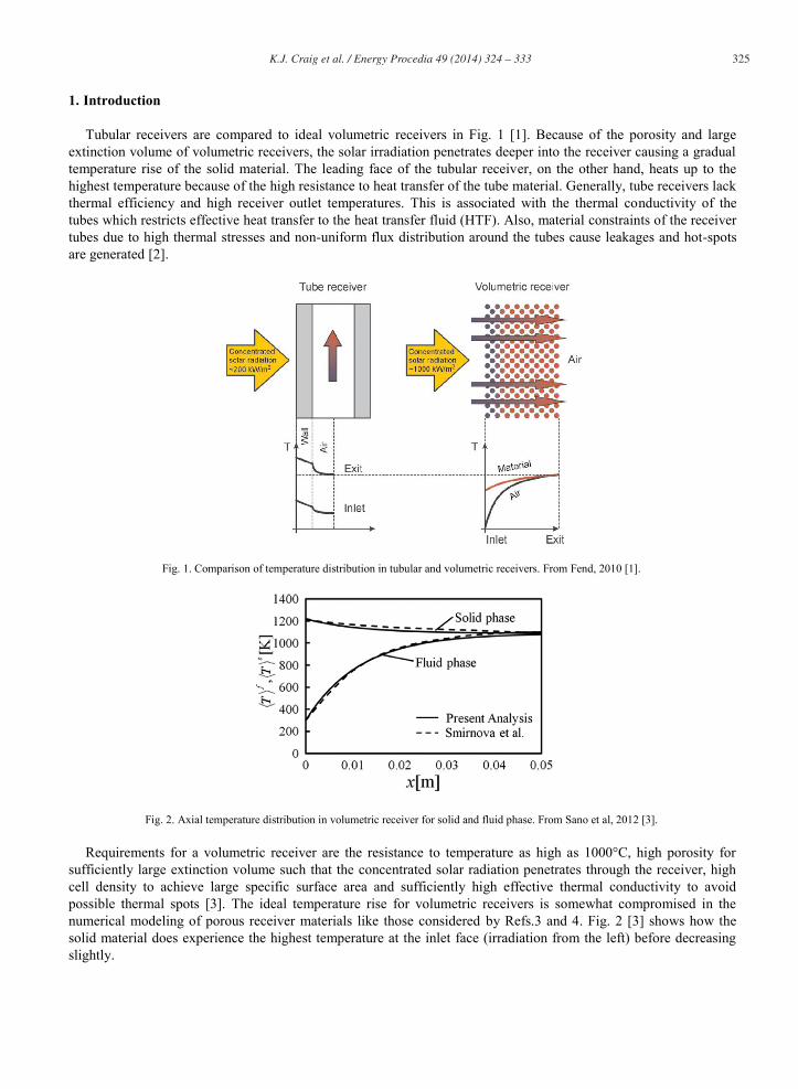
Tubular receivers are compared to ideal volumetric receivers in Fig. 1 [1]. Because of the porosity and large extinction volume of volumetric receivers, the solar irradiation penetrates deeper into the receiver causing a gradual temperature rise of the solid material. The leading face of the tubular receiver, on the other hand, heats up to the highest temperature because of the high resistance to heat transfer of the tube material. Generally, tube receivers lack thermal efficiency and high receiver outlet temperatures. This is associated with the thermal conductivity of the tubes which restricts effective heat transfer to the heat transfer fluid (HTF). Also, material constraints of the receiver tubes due to high thermal stresses and non-uniform flux distribution around the tubes cause leakages and hot-spots are generated [2].
Fig. 1. Comparison of temperature distribution in tubular and volumetric receivers. From Fend, 2010 [1].
Fig. 2. Axial temperature distribution in volumetric receiver for solid and fluid phase. From Sano et al, 2012 [3].
Requirements for a volumetric receiver are the resistance to temperature as high as 1000°C, high porosity for sufficiently large extinction volume such that the concentrated solar radiation penetrates through the receiver, high cell density to achieve large specific surface area and sufficiently high effective thermal conductivity to avoid possible thermal spots [3]. The ideal temperature rise for volumetric receivers is somewhat compromised in the numerical modeling of porous receiver materials like those considered by Refs.3 and 4. Fig. 2 [3] shows how the solid material does experience the highest temperature at the inlet face (irradiation from the left) before decreasing slightly.

326 K.J. Craig et al. / Energy Procedia 49 ( 2014 ) 324 – 333
For pressurized air as working fluid (as found in solarized gas turbines), a porous volumetric receiver would require a pressurized quartz window to enable the whole receiver to operate under high pressure. In an attempt to combine the benefits of the volumetric receiver as well as negate the need for a quartz window, the Hybrid Pressurized Air Receiver (HPAR) concept was proposed by Kretzschmar & Gauché [2]. HPAR consists of three zones, the secondary concentrator, the cavity and the secondary heat exchanger (which is a counter-flow heat exchanger). The secondary concentrator, called compound parabolic concentrator (CPC), is optional to the design. The receiver’s thermodynamic cycle can be separated into two different loops, i.e., a pressurized air loop, and the unpressurized air loop. Within the pressurized air loop compressed air is being preheated by the unpressurized air loop and enters the receiver cavity. Here, it is further heated by indirectly-irradiated tube bundles to the final maximum outlet temperature. The unpressurized air loop is similar to the open volumetric receiver concept where ambient air is being sucked into the receiver and is heated up by the absorber material. The enthalpy gained by the volumetric air stream is being recovered by means of a secondary heat exchanger.
The cavity consists of a transparent window (i.e. louvers or glass panes/tubes) and an array of absorber tubes. The third zone consists of a secondary heat exchange. The current paper is focused on the cavity of this concept, i.e., trying to find an optimal combination of heat penetration, re-radiation and external forced convection.
The process of finding an optimal combination involves the use of Computational Fluid Dynamics (CFD) and mathematical optimization. In order to model the correct heat input through solar irradiation, a test case was constructed to investigate how to represent solar flux from a heliostat field. The paper then describes how the cavity geometry was parameterized in order to enable the optimization process where design variables are modified in order to minimize an objective function and satisfy constraints. A base case was evaluated to illustrate different candidate performance parameters that can be used as objective functions.
2. Solar irradiation
The Discrete Ordinates (DO) thermal radiation model in ANSYS Fluent [5] can be used to model a solar irradiation source field by defining semi-transparent walls at the boundary of the computational domain. Each wall can be seen as a mirror reflecting solar irradiation at a specific specular angle. By dividing a plane into many subsections, and assigning an irradiation direction to each that is pointed towards a specific target, the concentration effect of a heliostat onto a central receiver can be approximated. Fig. 3 shows a test case geometry where a 12x12 array of square 0.125x0.125m sources point towards a target plane. The target is given an emissivity of 1 to allow it to absorb all incoming irradiation. Each source is given a direct irradiation value of 1.667MW/m2, a beam angle of 0.53° and a direction vector aimed at the center of the target. The source radiation flux distribution and target absorbed radiation flux is shown in Fig. 4. Note that the effective source values of the outlying sources are less due to the projection of the specified value onto the source direction. The concentration effect on the target can clearly be seen. An extension of this test case included a simplified cavity receiver with three tubes. The emissivity on the tube walls was set at 0.9 so that they absorb 90% of all incoming and reflected radiation, while the cavity walls have an emissivity of 0.1 to set reflectivity at 90% (the default setting in ANSYS Fluent was used in this work, i.e., emissivity equals absorptivity). The cavity surfaces are all opaque and gray and reflect diffusely. Their temperature was set at 10K to limit the emission component of radiation, i.e., the incoming radiation is either absorbed or reflected. The radiation flux at the cavity entrance is displayed in Fig. 5 together with the absorbed and reflected radiation in the cavity. The highest absorption occurs at the center of the tubes because of the shadowing effect of the cavity walls.
3. Parameterization of geometry
The parameterization capability of the geometry and mesh generator, GAMBIT, was extensively utilized in the definition of the receiver geometry. A master journal file was generated that calls other journal files and executes system commands that generate additional journal files that depend on parameter settings. In this way, the layout of the cavity, tubular arrangement, tube size, header and piping layout associated with the HTF loop, etc. can be automatically generated based on a set of defining input parameters.

K.J. Craig et al. / Energy Procedia 49 ( 2014 ) 324 – 333 327
Fig. 3. Geometry of test case for solar irradiation.
Fig. 4. Effective source distribution (left); Absorbed radiation flux on target (right) [W/m2].
A symmetric geometry in the vertical direction was considered. The structure of the geometry and mesh generation process is summarized in Fig. 6. In order to allow for a tubular layout of varying porosity (to allow solar irradiation to penetrate deeper into the cavity), an elliptical region was defined where tubes are spaced based on two defining dimensions (base pitch and front-facing pitch) as indicated in Fig.7. The rest of the cavity is populated using a regular triangular arrangement. Sample tube layouts generated in this fashion are shown in Fig. 7. To distribute the HTF through the cavity, a header system is used. Because of the à priori unknown location of tubes in the variable porosity region, logic is used to project a specific tube onto the nearest header (Fig. 8). In this way vertical banks of tubes are connected to a common header. The number of and size of the headers is dependent on the tube size, tube number and cavity size (see samples in Fig. 8). The routing between headers was implemented in a particular fashion so as to let the front-facing tubes have the coldest HTF and then snake through the domain. The forced convection in the cavity exterior to the tubes containing the HTF is enabled through slots in louvers on the left-hand faces in Fig. 7. The outlet of the cavity is in the form of multiple thin slots on the right-hand face in Fig. 7. Both inlet and outlet configurations are also parameterized.
144 Sources
Target
Focal point of all sources

328 K.J. Craig et al. / Energy Procedia 49 ( 2014 ) 324 – 333
a)
b) c)
Fig. 5. a) Radiation flux at cavity aperture; b) Absorbed radiation flux on cavity surfaces; c) Reflected radiation flux on cavity surfaces [W/m2].
4. CFD model settings
In order to combine the solar irradiation heat source with the cavity and HTF loop, certain modeling assumptions are made. The air external to the receiver through which the solar flux is transmitted is modeled as a solid zone that participates in radiation, but with zero absorptivity and the refractive index of air. Because of this assumption, the fluid flow and turbulence model equations are not solved in this zone, reducing the computing time of the model. The pressurized air inside the HTF loop is set to not participate in thermal radiation to reduce the zones where the expensive DO equations are solved. As the internal surfaces of the tubes and header pipes are locally at similar temperatures, this is a good assumption. This assumption implies that the heat transfer mechanisms inside the tubes are conduction and convection only, i.e., the heat source is conducted through the tube walls and then transferred to the HTF through convection. The header pipes and tubes external to the cavity are assumed to be perfectly insulated, i.e., an adiabatic wall assumption is made for these external surfaces.
The fluid external to the tubes inside the cavity is given separate properties from the HTF inside the tubes and headers. As the HTF pressure remains fairly constant, the incompressible ideal gas assumption is made, where the density is only a function of temperature. The SST k- turbulence model is used to model turbulence flow in both the HTF loop and external forced convection.

K.J. Craig et al. / Energy Procedia 49 ( 2014 ) 324 – 333 329
Generation process
1. Generate tube layout
2. Generate cavity domain
3. Generate tube faces, mesh and generate headers
4. Copy tubes with mesh and extrude to headers
5. Create groups from tube, header and cavity volumes
6. Mesh RHS tube headers and copy to LHS
7. Mesh cavity tubes, cavity and headers and pipes
GAMBIT Parameters (Example)
$width = 1000.0
$wdepth = 500.0
$height = 500.0
$gap_front = 100.
$gap_back = 50.
$gap_top = 50.
$base_pitch = 100.
$ellipse_yparam = 0.7
$ellipse_xparam = 0.65
$front_pitch = 120.
$tube_D = 45.0
$tube_t = 3.0
Fig. 6. Geometry and mesh generation process using journals and parameters in GAMBIT and example parameter set (dimensions in mm).
Fig. 7. Sample tubular layouts for different tube size and porosity parameters.
5. CFD results
5.1. Solar irradiation
The solar irradiation as modeled in a similar fashion as for the test case above is shown at the aperture of the cavity in Fig. 9 together with the radiation flux absorbed by the tubes. Emission is again limited by setting all the cavity surface temperatures to 10K. The integrated flux on the cavity aperture is 1.035MW/m2 or just over a 1000 suns for the source values used. The solar component of absorbed flux on the tubes is also plotted in Fig. 12 as a function of position into the cavity. It can clearly be seen how the absorbed flux decays into the cavity because of the blocking effect of the tubes. The figure also includes the combination of the solar and re-radiated component as discussed in Paragraph 5.4.
Base pitch Front pitch

330 K.J. Craig et al. / Energy Procedia 49 ( 2014 ) 324 – 333
a)
b)
Fig. 8. Sample header configurations a) Many, small tubes; b) Fewer, larger tubes, also showing tube projection onto closest header. Inserts showing tubular layout.
Fig. 9. a) Radiation flux at cavity aperture, b) Solar irradiation absorbed by tubes, c) Radiation reflected by cavity walls. All [W/m2].
Inlets (HTF)
Inlets (cavity)
Outlets (HTF)
Outlets (cavity)
Projection of tubes onto
headers
a) b) c)

K.J. Craig et al. / Energy Procedia 49 ( 2014 ) 324 – 333 331
5.2. Effect of porosity on forced convection flow patterns
A 2D case was simulated to illustrate the effect of tube arrangement on the expected forced convection flow patterns and hence convective heat transfer. A regular triangular arrangement, as would typically be found in a conventional heat exchanger was compared to a variable porosity layout with fewer tubes. Larger spacing between tubes would allow deeper penetration of solar irradiation, but should also allow more cooling fluid to pass through because of the lower flow resistance. It can be seen in Fig. 10 that short-circuiting of the cooling fluid between tubes is possible depending on the exact location of the inlet slots. The aim would be to optimize this flow distribution to investigate whether this would result in improved heat transfer at lower tube temperatures (see sample displayed in Fig.10c)).
5.3. Heating of HTF
To illustrate the flow and temperature patterns inside the HTF loop, and how even the distribution of flow from the headers is into a vertical bank of tubes, Fig. 11 shows the flow patterns and temperature distribution for a 0.15kg/s mass flow rate at 1MPa pressure with the solar heating applied as illustrated in Fig.9. The heating of the HTF is relatively even per pass through the cavity with the exception of the first row where the highest solar flux is experienced. This phenomenon suggests use of either different coatings on this set of tubes, or using solid quartz tubes as a buffer for this first row. Note the use of splitter plates in the headers to prevent short-circuiting of the header pipes into a specific set of tubes (located close to the header pipe outlet) in a vertical bank.
5.4. Absorption of radiation and re-radiation
When the conjugate heat transfer problem is solved, the tubes and cavity walls heat up due to the incoming solar irradiation and then also emit radiation that is proportional to the fourth power of temperature and the emissivity. The effect of this additional heat transfer mechanism can be seen in the sample plot of absorbed radiation flux on the cavity tubes versus position into the cavity in Fig. 12a). It can be seen that the re-radiation effect causes the absorbed radiation profile to penetrate deeper into the cavity when comparing the solar-only (corresponding to the plots in Fig.10) distribution with the combined solution. Fig. 12 also shows a sample tube outside temperature (Fig.12b)) and the heat flux transferred to the HTF on the internal tube surface (Fig.12c)). The tube temperatures are unrealistically high, indicating that there is room for improvement in the optimization process.
a)
b)
c)
Fig. 10. Velocity magnitude contours for cavity forced convection flow a) regular triangular arrangement, b) symmetric half of elliptical porous region [m/s], c) Sample temperature contours in cavity for case displayed in Fig.8b).

332 K.J. Craig et al. / Energy Procedia 49 ( 2014 ) 324 – 333
a) b)
Fig. 11. HTF flow in tubes and headers a) Velocity magnitude contours [m/s], b) Pathlines colored by Temperature [K], clipped at 1200K.
a)
b) c)
Fig. 12. As a function of position into cavity: a) Absorbed radiation flux on tubes (solar only versus solar and re-radiated) [W/m2], b) Tube outside surface temperature [K], tube internal transferred heat flux [W/m2].
Splitter plate

K.J. Craig et al. / Energy Procedia 49 ( 2014 ) 324 – 333 333
6. Candidate objective functions
The obvious choice for objective function is a measure that maximizes heat transfer between the incoming solar irradiation and the heat transfer fluid (HTF). In order to maximize this heat transfer the losses must be minimized. As the aim of the HPAR is to mimic a volumetric receiver using multiple tubes, the profile of heating is also important (refer Figs. 1 and 2). The shape of the temperature distribution and absorbed radiation distribution into the cavity can also be a measure which can be included in the optimization problem formulation. Other candidates include:
Deviation from an even temperature profile on the tube faces Temperature gradient(s) and associated differential thermal expansion on structural components Irreversibility, entropy generation (2nd law efficiency) Exergy destruction in specific regions of the cavity Heat transfer mechanism budget in different zones (radiative vs convective vs conductive) Cooling power required for tube external forced convection (flow rate×pressure drop obtained from
CFD simulation)
7. Conclusions and recommendations
The paper has described the process involved in the optimization of a cavity receiver using CFD. The following conclusions can be made:
CFD is able to model solar irradiation targeted at a cavity receiver in combination with the conjugate heat transfer problem. The Discrete Ordinates radiation model allows for both solar irradiation and re-radiation to be solved simultaneously.
A cavity receiver geometry can be parameterized so that parameters can be assigned as design variables in an optimization problem. The scripting capability of GAMBIT was used to generate the geometry and mesh in a fairly automated fashion.
Different performance parameters can be extracted from the CFD solution that can serve as objective functions and constraints in an optimization problem definition.
Future work includes the optimization of the cavity receiver for a set of conditions. These include extension of
the heliostat source definition, different operating conditions of the HPAR, and an extension to include the secondary heat exchanger. More representative optical properties, i.e., solar absorptance, reflectance, transmittance and thermal emissivity as a function of at least wavelength and temperature (using a hemispherical assumption to eliminate variation due to the two solid angles) will be considered for coatings on the cavity tubes and walls. These are implemented using User-Defined Functions (UDFs) in ANSYS Fluent.
Acknowledgements
The authors would like to acknowledge the support from the University of Pretoria (South Africa) and the South African National Research Foundation (DST-NRF Solar Spoke).
References
[1] Fend T, High porosity materials as volumetric receivers for solar energetics. Optica Applicata 2010; XL No. 2:271-284. [2] Kretzschmar H, Gauché P. Hybrid pressurized air receiver for the Sunspot cycle. 1st South African Solar Energy Conference (SASEC), 21-23
May 2012. [3] Sano Y, Iwase S, Nakayama A. A local thermal nonequilibrium analysis of silicon carbide ceramic foam as a solar volumetric receiver. J
Solar Energy Engineering 2012; 134:021006-1:021006-8. [4] Smirnova O, Fend T, Schwarzbözl P, Schöllgen D, Höhe L. Homogeneous and inhomogeneous model for flow and heat transfer in porous
materials as high temperature solar air receivers. Proceedings of the COMSOL Conference 2010 Paris. [5] ANSYS Fluent 14.5 User’s Guide, 2012.