a ir distr ibution specialist - flowtech - louvers.pdf · · 2011-11-30a ir distr ibution...
TRANSCRIPT

A I R DISTR I BUTION SPECIALIST
-
LOUVERS
GL Wall Gravity Louvers EAL Exhaust Air Louvers FAL Fresh Air Louvers FL Filter Louvers STL Sand Trap Louvers
FAISAL JASSIM INDUSTRIES (L.L.C.) P. 0. Box: 187 I Dubai, U.A.E.
Tel: +971 4 2"58 2640 Fax:+971 42 5.8 2641
E-mail: [email protected] Website: vvww.faisaljassim.ae
vvww.flowtechind.com
' ,

AIR DISTRIBUTION SPECIALIST
-~ Gravity Louvers (GL)
The GL is a wall mounted device that is composed of a set of horizontally mounted blades that are normally closed and are free to rotate arround their horizontal axis.
This louver serves as a non-return damper and can be used at the exit terminal of exhaust ducts and fans.
Certain pressure is usually required before the damper opens to expel the exhaust air, which ensures the elimination of back now.
The blades are made from light weight aluminium sheets, while the frame is made from extruded aluminium.
Rev. 0:2005/ I
• Wall Mounted Gravity Louvers (GL)
1-1

AIR DISTRIBUTION SP E CIALIS T
Free area ratio = 0.8 I for I 00% open blades.
To calculate the air flow rate:
Air flow= 0.81 X Neck area X Face Velocity
0.. 0 '-
0 Q) '-::I VI VI Q) '-a...
0.0 ro* o...fj
. ~
00 lf)l'!
0
0~ 70
0~ (V)cj
oro Nq 0
o(!; - cj
oo 0
0 0
~ ~
"""""" ~
~ io""""'
~
0.5 1.0 1.5 2.0 2.5 3.0 100 200 300 400 500 600
..,.,. ~
3.5 700
~
4.0 800
Face Velocity Based on Width (A) X Height (B)
~ ...,... V"
5.0 1000
~
m/s fpm
- Performance Chart of Gravity Louver- GL
1-2 Rev. 0:2005/ I
FLO ~TECH A IR D IST R IBUTION SPECIALIST
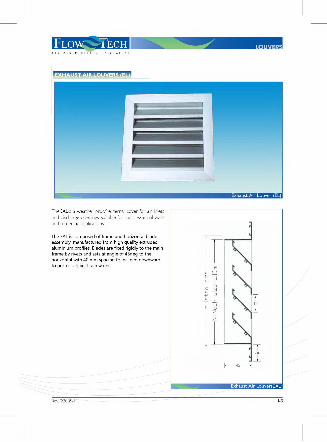
The EAL is a weather proof external cover for air inlets and discharge openi ngs, suitable for most external walls and screening applications.
The EAL is composed of frame and horizontal blade assembly, manufactured from high qua lity extruded aluminium profiles. Blades are fixed rigidly to the main frame by rivets and sets at ang le of 45deg to the horizontal with 40 mm spacing to inclined downward to protect aga inst rain water.
Rev. 0:2005/ I
Q; N lfl
() Q;
-t-> lfl _j
I I _j
J Exhaust Air Louver (EL)
r E: E:
C) .....-<
_j
II Q; N lfl
_y u Q; z II z
l r------45----l
Exhaust Air Louver(EALJ
1-3

FLow ~TEcH AIR D IST R IBUTIO N SPECIALIST
Free area rat io = 0.41 To calculate the air fiow rate:
Air flow= 0.41 X Neck area X Face Velocity
co ro* o...-5
.c;
oo O'<i: -o
OM co"! /
a. 0 0 '-
0 07 /
QJ '-::J
"' "' QJ '-a...
-.0~ 0
0~ 7 0
oco Mq
0
oO 0
0 0
v /' ~
1.0 200
~
2.0 400
Face Velocity Based on Width (A) X Height (B)
3.0 600
I I
/ v
m/s fpm
":""" Performance Chart of Exhaust Air Louver (EL)
1-4 Rev. 0:2005/ I

AIR D ISTRIBUTION SPECIALIST
- Fresh Air Louver (FAL)
The FAL is a simple form of filter louvers. It is composed of an exhaust louver with an aluminium fi lter fixed at the back.
The fresh air louver is suitable for use in air inlets of fresh air ducts and air handling units. It is also suitable for use at dirty air exhaust discharge.
. .,. Fresh Air Louver (FAL)
Rev. 0:2005/ I
The fi lter is made of washable aluminium media and is fixed on the back of gri lle. Fi lter is 25mm thick.
Also available as Fi lter Louver (FL) which is composed of an exhaust air louver fixed to a frame that contains a filter by means of stainless steel hinges.
4S
Filter Louver (FL)
1-5

FLOW -~TECH AIR DIS T RIB UT ION SPECIALIST
Free area ratio = 0.38 To calculate the air flow rate:
Air flow= 0.38 X Neck area X Face Velocity
co «J* o_{j
.~
oo ov: -o
a_ oN e co~ 0 0 Q) ....
0-.r-::::s VI ~"! VI 0 Q) ....
(l_
o:::' ..ro
-
oco Nq 0
- - I
~
1.5 200
..,. /
~ -
2.0 400
j /
v / v
3.0 600
I I
I I
m/s fpm
Face Velocity Based on Width (A) X Height (B)
Performance Chart of Fresh Air Louver (FAL). and Filter Louver (FL)
1-6 Rev. 0:2005/1

LOUVERSA I R D I S T R I B U T I O N S P E C I A L I S T
I-7Rev. 0:2005/1
SAND TRAP LOUVERS (STL)
Sand Trap Louvers (STL)
The STL is used to lower the dust loading of conven-tional filteration as it is designed to separate large size sand particles at low to medium speeds, it is also fitted with a bird screen mesh made of galvanized steel to protect against undesired objects. Insect screen of stain-less steel can be installed as optional.
The STL is a self emptying system, it has a set of holes at the bottom face of the casing to discharge separated sand particles.
The STL is made of aluminium sections. It is composed of two sets of inverted U channels, mounted vertically on two opposite rows.
Aluminium washable filter (optional) can be installed on the neck of the louver. Filter is 25mm thick.
2575
(A)
50 25 100
Standard DimensionsAny combination of A x B.
A4506007509001050120013501500165018001950
B45050060080010001200
Other size B, available on request by step of 50 mm.

FLOW ~~TECH AIR DISTRIBUTION SPECIALIST
Test conducted on similar equipment indicat ed a t ypical efficiency of 80% on AC coarse (20 - 200 micron) and 50% on AC fine test duct (I to 70 microns).
Standard Free area ratio = 0.33 (Standard dimensions are given above)
To calculate the air flow rate:
For normal operation ordinary condit ions, sand t rap louvers used for natural ventilation purpose are rated at a recommended Face velocit y of I .0 m/s.
Different sand trap louver arrangements may be provided to give other Free Area ratio as per customer requirement.
Air flow= 0.33 X Neck area X Face Velocity
1-8
(in-wg)
2
1.8
1.6
1.4
1.2
1.0
0.8
0.6
0.4
0.2 ~ -
0.5 100
I '#.
I 200
~~ --~ 1.5
300 2
400 Face velocity
d Pt (Pa) 500
I /
450
400
350
300
250
200
ISO
100
50
0
!1 Pt /
/
2.5 500
3 (m/s) 600(fpm)
Pressure drop
Selection table: Degree of filtrat ion and resistance as a function of aw speed.
~ \
' " ~ ' ~
1.5 1.1 u 11 ~ ). JJ u Fa.,..,...,_ - - Efficie nc Vs Face ve locit m m/sec
Rev. 0:2005/ I

FLOW~ECH AIR DIS T RIBUTION SPECIALIST
DOD- A X B-DDDD I I I I
RAL Code Color
Height in mm
L__------------------1 Width in mm
GL : Wall Gravity Louvers EAL : Exhaust A ir Louvers
L----------------------1 FAL : Fresh Air Louvers
STL - 1200 X 600 - 90 I 0
Stands for Sand Louver, I 200mm Width x 600mm Height, powder coated to RAL 90 I 0.
Rev. 0:2005/ I
FL : R~erLouvers STL : Sand Trap Louvers
1-9