optimal synthesis of the slider-crank mechanism for path ... · pdf fileii. the generalized...
TRANSCRIPT
The 14th IFToMM World Congress, Taipei, Taiwan, October 25-30, 2015 DOI Number: 10.6567/IFToMM.14TH.WC.OS2.008
Genliang CHEN1 Hao WANG2 Weidong YU3 Yong ZHAO4
State Key Laboratory of Mechanical System and Vibration,
Shanghai Key Laboratory of Digital Manufacture for Thin-walled Structures,
Shanghai Jiao Tong University, Shanghai 200240, P.R. China.
Optimal Synthesis of the Slider-crank Mechanism for Path Generation Based on the
Generalized Kinematic Mapping of Constrained Plane Motions
Abstract: This paper presents a new strategy for the
optimal synthesis of the planar slider-crank mechanism for
continuous path generations. Based on the generalized
kinematic mapping of constrained plane motions, the
desired path for the coupler link is mapped into the
three-dimensional projective space as a spatial surface,
which is regarded as the target kinematic manifold. Also,
the potential motions of the coupler link constrained by the
crank and the slider are projected on the target manifold in
the image space, whose difference can be regarded as an
alternative description for the kinematic conflict of the
mechanism with the design requirement. Thus, a metric for
the structure error between the candidate mechanism and
the ideal one for the desired path is set up in terms of the
area of a ruled surface, the distance surface intercepted
from the target manifold, which is also selected as the
objective function for the optimal synthesis. To obtain the
final optimum based on the initial design variables with
high convergence rate, the gradient descent algorithm is
introduced. A numerical example for the optimal synthesis
of the planar slider-crank mechanism for an elliptic
trajectory is studied to validate the effectiveness of the
proposed approach. Keywords: Optimal synthesis, Planar slider-crank mechanism,
Continuous path generations, Generalized kinematic mapping,
Gradient descent algorithm
I. Introduction
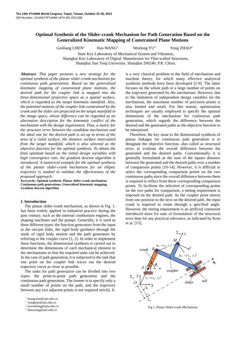
The planar slider-crank mechanism, as shown in Fig. 1,
has been widely applied in industrial practice during the
past century, such as the internal combustion engines, the
shaping machines and the pumps. Generally, it is used as
three different types: the function generators from the input
to the out-put links, the rigid body guidance through the
study of rigid body motion and the path generators by
referring to the coupler curve [1, 2]. In order to implement
these functions, the dimensional synthesis is carried out to
determine the dimensions of each mechanical element in
the mechanisms so that the required tasks can be achieved.
In the case of path generation, it is subjected to the task that
one point on the coupler link traces out the desired
trajectory curve as close as possible.
The tasks for path generation can be divided into two
types: the point-to-point path generation and the
continuous path generation. The former is to specify only a
small number of points on the path, and the trajectory
between any two adjacent points is not required strictly. It
1 [email protected] 2 [email protected] 3 [email protected] 4 [email protected]
is a very classical problem in the field of mechanism and
machine theory, for which many effective analytical
synthesis methods have been developed [2-9]. The latter
focuses on the whole path or a large number of points on
the trajectory generated by the mechanism. However, due
to the limitation of independent design variables for the
mechanism, the maximum number of precision points is
also limited and small. For this reason, optimization
techniques are usually employed to specify the optimal
dimensions of the mechanism for continuous path
generation, which regards the difference between the
desired and the generated paths as the objective function to
be minimized.
Therefore, the key issue to the dimensional synthesis of
planar linkages for continuous path generation is to
designate the objective function, also called as structural
error, to evaluate the overall difference between the
generated and the desired paths. Conventionally, it is
generally formulated as the sum of the square distance
between the generated and the desired paths over a number
of comparison points [10-14]. However, it is difficult to
select the corresponding comparison points on the two
continuous paths since the overall difference between them
is required to reflect from these corresponding comparison
points. To facilitate the selection of corresponding points
on the two paths for comparison, a timing requirement is
imposed on the desired path. As the coupler point moves
from one position to the next on the desired path, the input
crank is required to rotate through a specified angle.
However, the timing requirement is an artificial constraint
introduced more for ease of formulation of the structural
error than for any practical relevance, as indicated by Kota
et al. [15].
Fig.1. Planar Slider-crank Mechanism.

For the sake of avoiding making point-by-point
comparison between the desired and the generated paths,
some alternative indices have been proposed as metrics of
the structural error to evaluate the overall difference of the
paths. Cheung et al. [16] introduced the concept of
orientation structure error of the fixed link for crank-rocker
mechanisms to reflect the overall difference between the
desired and generated path. In their model, the desired
curve of the coupler was considered as the kinematic input
of the mechanism. The orientation of the fixed link is
released from the design variables, whose variation is
defined as the alternative metric of the structure error
between the generated and the desired paths. Therefore,
according to the kinematics of the mechanism, the
difference between the two curves has been transformed to
a scalar function regarded as the objective function to be
minimized. In the same manner, they introduced the
position structural error of the fixed guider for the
dimensional synthesis of slider-crank mechanisms [17].
Taking account the design specifications in the industrial
practice, Figliolini et al. [18] addressed attentions to the
shape and the overall size of the coupler curves for the
dimensional synthesis of slider-crank mechanisms for
automatic machinery.
On the other hand, the metric of the distance norm
between the desired and generated paths may be
overestimated when they are translated with respect to
each other. For this reason, Fourier descriptors are
introduced by Kota et al. [15, 19] to represent the coupler
curves, which are invariant with respect to the translation,
rotation and scaling of the curves. Another advantage of
this method is the reduction of the size of the design space
of the dimensional synthesis problem because the
unknown variables are divided into two sets, one set of
design variables determines the shape of the generated
curve and the other defines the size, position, and
orientation. On this basis, many researchers [20-23] have
contributed their efforts to push forward the techniques for
the dimensional synthesis of planar mechanisms for
continuous path generation.
In addition, structural error is a highly non-linear and
multi-modal function in a multi-dimensional design space.
Finding the global optimum of this function is a formidable
problem. So, success is not always guaranteed. As a result,
evolutionary algorithms are usually employed to carry out
the optimal synthesis, such as the Neural Networks [20],
the Genetic Algorithms [14, 24] and the Particle Swarm
Optimization [25]. Additionally, some other methods [14,
26-28] have also been proposed to implement the
dimensional synthesis of planar mechanisms for path
generation.
This paper presents a new strategy for the optimal
synthesis of the planar slider-crank mechanism for the task
of continues path generation. The main idea is to measure
the overall “difference” between the candidate mechanism
and the ideal one for the desired path in an alternative
manner with intuitive physical insights. As a result, the
method of the generalized kinematic mapping of
constrained plane motions [34] is utilized to transform the
dimensional synthesis of planar mechanisms into the
three-dimensional projective space as a spatial geometry
problem. Then, the concept of target kinematic manifold is
introduced to represent the desired path for the coupler link
more comprehensively in the image space. On the basis of
this expression, not only the position of the coupler point
but also the orientation of the link is imposed into the
displacement to represent the four-bar motion completely.
In consequence, the distance between the constraint
manifold and the target one for the coupler link can be
defined in the three-dimensional image space, which not
only reflects the distance of the coupler point from the
desired one, but also indicates the way how to move the
coupler link onto the desired path at the same time.
In order to simplify the geometric derivation, an
alternative representation for the structure error between
the candidate mechanism and the ideal one is introduced as
the conflict of the kinematic constraints of the crank and
the slider ends on the target manifold. Then, the ruled
surface intercepted from the target manifold by the circular
and the linear constraints is defined as the distance surface
for the problem of dimensional synthesis. The area of this
surface is modeled up as a metric for the overall difference
between the generated and the desired trajectory of the
coupler motion, which is selected as the objective function
of the optimization problem for the dimensional synthesis.
In order to obtain the final optimum based on the initial
design variables, the gradient descent algorithm is
introduced in our model.
The rest of the paper is organized as follows. Firstly,
section II gives a brief introduction to the generalized
kinematic map-ping of constrained plane motions, which is
the basis of the new strategy for the optimal synthesis
proposed in this paper. Then, the position analysis of the
studied slider-crank mechanism is presented in section III.
Thereafter, in section IV the kinematic manifolds for the
coupler link is generated and analyzed in the image space
as two typical kinematic constraints, the circular constraint
and the linear one. Then, a metric for the structural error of
the candidate mechanism is set up on the target manifold of
the coupler, which is selected as the objective function for
the problem of dimensional synthesis. In section VI, the
gradient descent algorithm is discussed briefly as the
searching algorithm. Then, a numerical example is studied
in section VII to validate the effectiveness of the proposed
method. Lastly, some conclusions are drawn in section
VIII.
Fig.2. Plane displacements of a
constrained moving body.

II. The Generalized Kinematic Mapping of
Constrained Plane Motions
As shown in Fig. 2, the plane displacement ( , , )a b D
of the moving body A with respect to the fixed frame Σ
can be generally given by the homogeneous linear
transformation as
cos sin
sin cos
0 0 1
X a x
Y b y
Z z
(1)
where ( , )a b and are the translational and rotational
components of the displacement. Vectors ( , , )Tx y z and
( , , )TX Y Z represent the homogeneous coordinates of
the point Q in the local frame E attached to A and the
fixed one , respectively.
According to the definition introduced by Grünwald[30]
and Blaschk[31], the plane displacements can be mapped
onto the image points in a three-dimensional projective
space in terms of the kinematic mapping [32, 33] as
1 11 2 3 4 2 2
1 1
2 2
1
2
1
2
: : : ( sin cos )
: ( cos sin )
: 2sin
: 2cos
X X X X a b
a b
(2)
Then, there exist a general closed curve ( ) on the
plane, under which the motion of body A is constrained at Q , as shown in Fig. 2. In other words, the fixed point Q
on A will always stay on the curve when it moves.
By substituting Eq.(2) and the constraint curve into
Eq.(1) and after some algebraic reduction, the image
surface of the constrained (under ) plane motion of body
A can be obtained in the three-dimensional projective
space as
3 4 3 41
4 3 4 32
1 1( )
2 2
X X X XX x
X X X XX y
F (3)
where ( , )Tx y is the Cartesian coordinate of the point
Q in the local frame E .
Fig.3. Constraint manifold of the plane
motion constrained by the planar closed
curve
Equation (3) is regarded as a general form of the image
surface in the projective space corresponding to the plane
motion constrained by the curve . Since the constraint
curve is general in a parametric form. It is obvious that the
image surface expressed in the general form is independent
from the concrete forms of the constraint curves. In other
words, it can be stated that the generalized kinematic
mapping of constrained plane motions is invariant from the
exact types of the constraints. Furthermore, the image
surface can be normalized conveniently by letting 4X 1
under the assumption of , which is illustrated in Fig.
3.
Furthermore, some intuitive geometric interpretations
between the constrained motion on the Euclidean plane
and its image surface in the projective space have been
revealed in our previous research[34].
As shown in the figure, there are two kinds of special
curves can be extracted from the spatial surface. One is the
intersection curves with horizontal planes, denoted as
0 in Fig. 3 (here 3X cot ), which can also be
regarded as contours of the surface at different levels.
These curves perform a pure translation along the
constraint curve on the plane with the specified rotation
angle of 02 . Moreover, the shapes of these curves
are all similar to the original constraint one, which can be
transformed from the original constraint curve according
to an affine mapping consisting of a translation, a rotation
and a scaling consequently. The other kind of curves is the
straight lines denoted by 0 , as shown in the figure.
These lines correspond to the motions of pure rotation
about a fixed point on the constraint curve specified by 0 .
The directions and the intersection points (with the zero
horizontal plane in the projective space) of these lines can
be determined by both the coordinates of the concerned
point on the moving plane and the rotating center on the
constraint curve according to Eq.(3). Therefore, these
image surfaces can be regarded as ruled surfaces in the
projective space which are generated by sweeping an
arbitrary line along any of the curves. Thus, the curves are named as the directrix, also called the base
curve, of the ruled surface and the lines are called the
rulings or generators.
Fig.4. Geometric presentation for the
kinematics of the slider-crank mechanism.

Based on the above properties, a surface coordinate
system, the - frame, can be established for each image
surface of constrained plane motions, as shown in Fig. 3.
Obviously, the two coordinates are independent of each
other and can be regarded as alternative representation of
the rotation pivot and angle of the displacements along the
plane motion. Thus, for each point on the image surface,
the corresponding plane displacement can be obtained
directly from its - coordinates according to the
generalized kinematic mapping (Eq.(3)), vice versa. The
image surface in the projective space is also called the
constraint manifold [33, 35] corresponding to the plane
motion of the moving body under the constraint of the
closed curve on the plane.
Due to the space limitation, this section only presents a
brief introduction about the generalized kinematic
mapping of constrained plane motions. The detailed
discussion on this approach can be found in [34].
III. Position Analysis of the Mechanism
As illustrated in Fig. 1, there are totally eight design
variables for the slider-crank mechanism, namely the
position of the pivot for the fixed revolute joint A:
0 0( , )T
A x y r , the length of the crank AB: 1l , the
geometric dimensions for the coupler link BCM:
1 2( , , )T
c c c cx x y D and the position and orientation of the
rail for the prismatic joint: 0 0 0( , )Td p . Here, it should
be noted that the positions (orientations) of the links are
related to the initial reference frame O fixed on the
ground, and the geometric dimensions of the coupler link
are expressed in the local frame M attached to it.
The kinematics of this mechanism can be transformed to
a geometry problem as shown in Fig. 4. The rotation angle
of the crank 1 is considered as the kinematic input of the
mechanism. Then, the position of the pivot of the revolute
joint B can be obtained as
1
1
1
cos
sinB A l
r r (4)
Thus, according to the planar projective geometry, the
position of the point D can be derived conveniently as
0 00 0 ( )T
D L L B r r u u r r (5)
where 0 0 0 0(cos , sin )T
L d r is the position vector of
the point 0L and 0 0 0( sin , cos )T u represents the unit
direction vector for the rail of the prismatic joint.
Therefore, the position of the pivot of the revolute joint C , namely the location of the slider, can be obtained as
0C D sl r r u (6)
where 2
2 1( ) ( ) ( )T
s c c D B D Bl x x r r r r denotes a
half of the length of the chord CC . And 1 is the
coefficient distinguishing different assembly
configurations of the mechanism.
Finally, the position of the coupler point M can be
obtained as
1M B c c Rr r ρ (7)
where 1 1( , )T
c c cx y ρ is the position vector of the revolute
joint B in the local frame M . cR represents the rotation
matrix of the coupler link with respect to the initial frame
O , which can derived as
2 2
2 2
cos sin
sin cosc
R (8)
where 2 denotes the rotation angle of the coupler, as
shown in the figure, which can be determined according to
the direction of the line BC .
Consequently, when the crank rotates through a full turn,
the path of the coupler point M can be traced out as a
closed curve according to the above steps in an analytical
way. As an example, the curve K in Fig. 4 is a potential
generated path of the studied mechanism.
IV. Constraint Manifold of the Mechanism
The coupler link in the slider-crank mechanism, which
in a sense can be regarded as the end-effector, moves under
the constraints from the fixed ground through two ends.
One is the crank end constraining the position and
orientation of the coupler link through a revolute joint, and
the other is the slider end through a prismatic joint.
In particular, the crank end imposes a circular constraint
on the coupler link through the revolute joint B. At the
same time, the motion of the coupler link is also
constrained on the line specified by the slider end at the
joint C. Then according to the generalized kinematic
mapping of constrained plane motions presented in the
above section, the constraint manifolds caused by the two
ends can be obtained conveniently via substituting the
constraint curve ( )F in Eq.(3) with the specified circle
and line, respectively.
Since the images of the constraint manifolds are ruled
surfaces, their algebraic equations can be expressed in a
unified form as
1
2
3
( , ) ( ) ( )
X
X
X
f b u (9)
where b is the directrix of the ruled surface, also called
the base curve, and u is the director curve as discussed in
the above section.
Theoretically, each of the curves on the manifold
can be selected as the directrix. Here, in order to simplify
the algebraic derivation, the curve with / 2 (namely
0 , the coupler translates along the constraint curve
with no rotation) is designated as the base curve. Then, for
the kinematic manifold under the circular constraint
through the crank end, the directrix can be derived as a
circle on the horizontal plane at 3 0X .
1 1
0 1 cos1( )
1 0 sin2A cl
b r ρ (10)
where 1 is the rotation angle of the crank.
Otherwise, the director curve can be derived as the
direction vector of the generators of the ruled surface.
1 1
cos1
sin2
2
A cl
r ρu (11)
and 3X in Eq.(9).

Fig.5. Constraint manifolds of the coupler
link caused by the crank and the slider
ends and their intersection
In the same manner, the directrix and the director curve
for the kinematic manifold under the linear constraint can
be obtained as
00 2
0 11( )
1 02L c
b u r ρ (12)
00 21
2 2
L c
u r ρu (13)
As a consequence, both of the two constraint manifolds
can be obtained based on the above equations and the
dimensions of the mechanism, which are illustrated in Fig.
5. Furthermore, it can be approved that the constraint
manifold caused by the crank end is a hyperboloid of one
sheet and the other caused by the slider end is a hyperbolic
paraboloid[36].
In the end, the final constraint manifold for the coupler
link can be obtained as the intersection of the two
generated kinematic manifolds, which is a spatial closed
curve in the projective image space, as shown in the figure.
It is known as the image curve of four-bar motion in
kinematic literatures [32, 33]. And the coupler will travel
along this curve when the crank rotates through a full turn.
It should be noted that the final constraint manifold for the
coupler is an overall description, including both the
position and orientation, for the link’s motion in the image
space. And it is invariant of the selection of the coupler
point.
V. Metic for the Structure Error on the Kinematic
Manifold
In the above section, the constraint manifold for the
coupler link has been obtained as a spatial closed curve in
the three-dimensional projective space.
On the other hand, by regarding the desired path as a
kinematic constraint of the coupler, a ruled surface (similar
to the one illustrated in Fig. 3), which is defined as the
target manifold for the coupler, can also be obtained in the
image space according to the generalized kinematic
mapping discussed in section II. Any point on this surface
represents a displacement of the coupler satisfying the
design requirement, namely, the coupler point of the
mechanism lies on the desired path. If the whole constraint
manifold is totally on the target one, the candidate
mechanism can generate the desired path for the coupler
and we can say that it is an ideal one for the path generation
synthesis. Otherwise, the difference between the generated
and the desired paths can be mapped into the image space
as the closeness of the constraint manifold to the target one
for the coupler link. Comparing with the structure error set
up on the Euclidean plane, the model in the image space
not only concerns with the point-to-point distance between
the generated and the desired paths, but also specifies the
way how to move the coupler link from the current
configuration to some others meet the design requirement.
However, it is a metric of distance between a spatial
curve and a surface in the three-dimensional projective
space, which is not very convenient to be set up properly.
Therefore, the structure error between the candidate
mechanism and the ideal one is modeled up in the image
space in an alternative way.
As discussed in the above section, due to the kinematic
constraints caused by the crank and the slider ends, the
displacements of the coupler link will be restricted on the
circular and the linear constraint manifolds simultaneously.
To completely meet the design requirement, all these
displacements should be bound to the target manifold as
well. Then, by intersecting the circular constraint manifold
and the target one, a spatial curve can be obtained as the
feasible motion of the coupler under the kinematic
constraint through the crank end. So does the one through
the slider end. Thus, two spatial curves are derived on the
target manifold as shown in Fig. 6, which reflect the
perfect motions of the coupler link satisfying the kinematic
constraints due to the crank and the slider ends,
respectively. If these two curves are completely matched
with each other, the candidate mechanism also can
generate the desired path for the coupler which means it is
an ideal one for the design requirement. So, the difference
between these two curves is regarded as an alternative
metric of the structure error between the candidate
mechanism and the ideal one in the image space.
Both of the feasible motions for the coupler are on the
target manifold which is a ruled surface in the projective
space. Then, for each point on one curve, there always
exists a corresponding point on the other curve to make the
line segment between these two points collinear with the
generator of the ruled surface passing through either of
them, as the line ( )t δ and the point s cA A- illustrated in
Fig. 6. On the other hand, for each generator on the target
kinematic manifold, a unique pair of intersection points
can also be specified on the two curves for feasible
motions, respectively.
Therefore, for each pair of the corresponding points, a
distance can be defined on the kinematic manifold in terms
of the length of the associated generator, which can be
represented as
( ) ct s (14)
where c , s are the parametric coordinates of the
intersection points, as the one indicated in (9).
For the whole desired path, it generates a new ruled
surface in the image space which actually is the specific
part of the target manifold intercepted by the two curves, as
illustrated in Fig. 6. It is called the distance surface
between the motions of the coupler constrained by the
crank and the slider ends on the target manifold, which can

be represented as
( , ) ( ) (1 ) ( )c st t t r b b (15)
where [0,1]t . Vectors ( )c b and ( )s b represent the
feasible motions of the coupler link to the crank and the
slider ends, respectively.
Finally, the area of the distance surface can be defined as
the structure error between the candidate mechanism and
the ideal one for the desired path. The area function can be
represented as 1 2
0 0( ) (1 ) ( ) ( ) ( )s c s s ce A dt t t d
b b b b (16)
Fig.6. Projection structure error on the
target manifold
VI. Optimization Algorithm
Since the structure error of the mechanism has been
projected on the target manifold as the area of the distance
surface, the problem of dimensional synthesis for
continuous path generation can be set up as a constraint
optimization problem as
min ( )
s.t.
se f
D
X
X (17)
where X represents the vector of design variables
consisting of the dimensions and location of the
mechanism. D is the design space which specified
according to a set of constraints, such as the limitation of
the link dimensions, the Grashof’s criteria, and so on.
To obtain the final optimum based on the given
parameters with high convergence rate, the gradient
descent algorithm is introduced to find the local minimum
of the structure error established on the target kinematic
manifold [37].
The gradient descent algorithm is also called steepest
descent. If the multivariable function ( )f X is defined and
differentiable in a neighborhood of a point 0A , then
( )f X decreases fastest in the direction of the negative
gradient of f at 0A , 0( )f A . Then, point 1A is
calculated through the following equation,
1 0 0( )f A A A (18)
where is step size, then
0 1( ) ( )f fA A (19)
Considering the sequence 0 1 2, , ,...A A A which can be
calculated by the following equation,
1 ( ),n 0n n n nf A A A (20)
we have
0 1 2( ) ( ) ( ) ...f f f A A A (21)
Applying the algorithm to our model of optimal synthesis
of the slider-crank mechanism for continuous path
generation, the problem can be set up conveniently. If
( )nf A converges to a value which is less than the
structure error limit we set, then nA will be chosen as the
desired design variables.
VII. A Numerical Example
In the above sections, a metric for the structure error
between the candidate mechanism and the ideal one for the
desired path has been established based on the generalized
kinematic mapping of constrained plane motions. Thus,
the closeness of the generated and the desired paths can be
evaluated by the area of the distance surface on the target
manifold. In this section, a numerical example for the
dimensional synthesis will be provided to demonstrate the
effectiveness and efficiency of the proposed method.
Unlike some literatures synthesizing the planar
mechanisms for some paths similar to their inherent ones,
in the numerical example we assigned a much more
general closed curve, an ellipse, as the target for the
dimensional synthesis of the slider-crank mechanism. The
major and the minor axis of the ellipse are 2 1.6a and
2 1b . And the center of the ellipse is located at the origin
of the initial reference frame where the major axis is
parallel to the X-axis of the initial frame. Thus, it can be
expressed as
cos
: , 0, 2sin
x at y b
(22)
Then, based on the gradient descent algorithm presented
in the above section, the dimensional synthesis can be
carried out for the desired path.
The feasible motions to the crank end and the slider end
can be expressed as
3 0 111
1
3 012
3 3
1 cos1( )
1 sin2
c
c
X x xXl
X y yX
X X
R (23)
3 21 0 0
0
32 0 0
33
' '
' '
cos sin11( d )
12 sin cos
c
c
X xX
X yX
X X
R(24)
where R is rotation matric defined as
cos sin
sin cos
R , and
0 0
'
2
denotes the
direction angle of the constrained line.
Meanwhile, the image surface of the ellipse curve is
expressed as
3 21
0
3 22
3 3
1 mcos1( )
1 n sin2
XX
XX
X X
C (25)
where 0
C is the center of the ellipse curve.
By substituting Eq.(25) into Eq.(23) and Eq.(24),
respectively, the expressions of the 2( )s b and 2( )c b can
be obtained. Because the analytical solution of the area

function se is difficult to be obtained, so discrete numerical
method is utilized to calculate sE , where 2 2
sis i ciE . sE and se are equivalent
because the variation tendencies of them are the same. ci
and si can be obtained according to 2( )s b and
2( )c b .Then gradient matrix is obtained as
0 0 2 00
( )'
T
s s s s s s
c c
E E E E E Ef
x y y x d
X (26)
where only 6 design variables’ derivatives are calculated
because only 6 of the 8 variables are independent.
Normally, if the 8 design variables are specified randomly,
the intersection of the target manifold and the circular
constrained manifold is not a piece of surface, as illustrated
in Fig.7. Then the crank can’t rotate a whole circle and
degenerate to a rocking bar.
Fig.7. The intersection of the target
manifold and the circular constrained
manifold
So once the target path is specified, 1l and
1 become
determined values to meet the constraint condition of the
slider-crank mechanism. The value of 1l +
1 equals to the
longest distance between the point A in Fig.4 and the point
on the target path. The absolute value of 1l -
1 equals to
the shortest distance between the point A and the point on
the target path. In this way, 1l and
1 can be obtained by
solving a quartic equation which represents the problem of
the longest and shortest distance between a point out of the
ellipse curve and the point on the curve.
Back on track, based on the initial design variables, by
substituting Eq.(26) into Eq.(20) repeatedly, the ideal
design variables nA are obtained.
The initial design variables and the optimization results
are illustrated in TABLE I and TABLE II. The projection
structure error on the target manifold before optimizing is
illustrated in Fig.8 and the one after optimizing is
illustrated in Fig.9. The generalized coupler curve of the
optimal is drawn in Fig.10 comparing with the desired and
the initial ones. Fig.11 shows the fast convergence of the
goal function to a near optimal solution in only 14
iterations. The elapsed time is 24.366292 seconds on a
workgroup of DELL OPTIPLEX980 (Intel(R) Core(TM)
i7 CPU 870 @2.93GHz, Ram 8.00GB)
0 0( , )Tx y 1l 1 2( , , )T
c c cx x y00
'( , )Td
(-0.62, -3.05) 0.52 (1.78, 6.89, -2.56) (-1.30, 0.01)
TABLE I. Initial design variables for
the dimensional synthesis
0 0( , )Tx y 1l 1 2( , , )T
c c cx x y00
'( , )Td
(-0.66, -3.00) 0.52 (1.64, 6.88, -2.60) (-1.15, 0.03)
TABLE II. Optimization results for
the dimensional synthesis
Fig.8. Projection structure error on the
target manifold before optimizing
Fig.9. Projection structure error on the
target manifold after optimizing

Fig.10. Generated coupler curve of the
optimization slider-crank mechanism to
the dimensional synthesis.
Fig.11. The changing of the optimal value
in the iterative process
VII. Conclusions
In this paper, we proposed a new strategy for the
dimensional synthesis of the slider-crank mechanism as a
generator for continuous paths. An effective and
meaningful metric for the structure error between the
candidate mechanism and the ideal one is set up in the
image space in terms of the conflict between the constraint
manifolds on the target one. Unlike the point-to-point
position comparison, the distance representation in the
three-dimensional projective space reflects the inherent
characteristics of the four-bar motions which perform
coupling movement combined both with translation and
rotation. Therefore, it is a more general description for the
structural error and states the problem of dimensional
synthesis for planar mechanisms in a simple geometric
interpretation with intuitive physical insight. The gradient
descent algorithm is employed to find the final optimum of
the dimensions of the mechanical elements for the design
requirement. The numerical result has shown the
effectiveness of the proposed approach.
Acknowledgement
This research is jointly supported by the National
Science Foundation of China (NSFC) under Grant
51305256 and Grant 11472172, and the National Basic
Research Program of China (973 Program) under research
grant 2014CB046600.
References
[1] C. H. Suh, C. W. Radcliffe, 1978. Kinematics and Mechanism Design, Wiley, New York.
[2] R. Hartenberg, J. Denavit, 1964. Kinematic Synthesis of Linkage, McGraw-Hill, New York.
[3] A. Erdman, 1981. “Three and Four Precision Point Kinematic Synthesis of Planar Linkages”, Mechanism and Machine Theory, 16 (5), pp. 227-245.
[4] C. Wampler, A. Morgan, A. Sommese, 1992. “Complete Solution of the Nine-Point Path Synthesis Problem for Four-Bar Linkages”, Journal of Mechanical Design, 114 (1), pp. 153-159.
[5] Z. Luo, J. Dai, 2007. “Patterned Bootstrap: A New Method That Gives Efficiency for Some Precision Position Synthesis Problems”, Journal of Mechanical Design, 129 (2), pp.173-183.
[6] A. Perez, J. McCarthy, 2004, “Dual Quaternion Synthesis of Constrained Robotic Systems”, Journal of Mechanical Design, 126 (3), pp. 425-435.
[7] X. Huang, et al., 2009. “Solving a Planar Four-Bar Linkages Design Problem”, In Proceedings of the 2009 IEEE International Conference on Information and Automation, June, 2009, Zhuhai/Macau, China.
[8] Brunnthaler K, Pfurner M, Husty M. Synthesis of planar four-bar mechanisms[J]. Transactions of the Canadian Society for Mechanical Engineering, 2006, 30(2): 297.
[9] Husty M L, Pfurner M, Schröcker H P, et al. Algebraic methods in mechanism analysis and synthesis[J]. Robotica, 2007, 25(06): 661-675.
[10] R. Fox, K. Willmert, 1967. “Optimum Design of Curve-generating Linkages with Inequality Constraints”, Journal of Engineering for Industry, 89 (1), pp. 144-152.
[11] J. Angeles, A. Alivizatoss, R. Akhras, 1988. “An Unconstrained Nonlinear Least-square Method of Optimization of RRRR Planar Path Generators”, Mechanism and Machine Theory, 23 (5), pp. 343-353.
[12] J. Cabrera, A. Simon, M. Prado, 2002. “Optimal Synthesis of Mechanisms with Genetic Algorithms”, Mechanism and Machine Theory, 37 (10), pp. 1165-1177.
[13] R. Sancibrian, F. Viadero, P. Garcia, A. Fernandez, 2004. “Gradient-based Optimization of Path Synthesis Problems in Planar Mechanisms. Mechanism and Machine Theory, 39 (8), pp. 839-856.
[14] A. Smaili, N. Diab, N. Atallah, 2005. “Optimum Synthesis of Mechanisms Using Tabu-gradient Search Algorithm”, Journal of Mechanical Design, 127 (5), pp. 917-923.
[15] I. Ullah, S. Kota, 1997. “Optimal Synthesis of Mechanisms for Path Generation Using Fourier Descriptors and Global Search Methods”, Journal of Mechanical Design, 119 (4), pp. 504-510.
[16] H. Zhou, E. Cheung, 2001. “Optimal Synthesis of Crank-rocker Linkages for Path Generation Using the Orientation Structural Error of the Fixed Link”, Mechanism and Machine Theory, 36 (8), pp. 973-982.
[17] H. Zhou, K. Ting, 2002. “Adjustable Slider-crank Linkages for Multiple Path Generation”, Mechanism and Machine Theory, 37(5), pp. 499-509.
[18] G. Figliolini, M. Conte, P. Rea, 2008. “Analysis and Synthesis of Slider-crank Mechanisms for Automatic Machinery”, In Proceedings of the 2008 ASME Design Engineering Technical Conferences, Aug. 2008, Brooklyn, NY, USA.
[19] I. Ullah, S. Kota, 1994. “A More Effective Formulation of the Path Generation Mechanism Synthesis Problem”, In Proceedings of the 1994 ASME Design Engineering Technical Conferences, September, 1994, Minneapolis, USA.
[20] A. Vasiliu, B. Yannou, 2001. “Dimensional Synthesis of Planar Mechanisms Using Neural Networks: Application to Path Generator Linkages”, Mechanism and Machine Theory, 36 (2), pp. 299-310.
[21] Y. Liu, R. Xiao, 2005. “Optimal Synthesis of Mechanisms for Path Generation Using Refined Numerical Representation Based Model and AIS Based Searching Method”, Journal of Mechanical Design, 127 (4), pp. 688-691.
[22] A. Smaili, N. Diab, 2007. “A New Approach to Shape Optimization for Closed Path Synthesis of Planar Mechanisms”, Journal of Mechanical Design, 129 (9), pp. 941-948.

[23] J. Buskiewicz, R. Starosta, T. Walczak, 2009. “On the Application of the Curve Curvature in Path Synthesis”, Mechanism and Machine Theory, 44 (6), pp. 1223-1239.
[24] G. Roston, R. Sturges, 1996. “Genetic Algorithm Synthesis of Four-bar Mechanisms”, Artificial Intelligence for Engineering, Design, Analysis and Manufacturing, 10 (5), pp. 371-390.
[25] R. McDougall, S. Nokleby, 2008. “Synthesis of Grashof Four-bar
Mechanisms Using Particle Swarm Optimization”, In Proceedings of the 2008 ASME Design Engineering Technical Conferences, Aug. 2008, Brooklyn, NY, USA.
[26] K. Watanabe, 1992. “Application of Natural Equations to the Synthesis of Curve Generating Mechanisms”, Mechanism and Machine Theory, 27 (3), pp. 261-273.
[27] J. McGarva, 1994. “Rapid Search and Selection of Path Generating Mechanisms from a Library”, Mechanism and Machine Theory, 29 (2), pp. 223-235.
[28] X. Zhang, J. Zhou, Y. Ye, 2000. “Optimal Mechanism Design Using Interior-point Methods”, Mechanism and Machine Theory, 35 (1), pp. 83-98.
[29] N. Nariman-Zadeh, M. Felezi, A. Jamali, M. Ganji, 2009. “Pareto Optimal Synthesis of Four-bar Mechanisms for Path Generation”, Mechanism and Machine Theory, 44 (1), pp. 180-191.
[30] J. Grünwald, 1911. “Ein abbildungsprinzip welches die ebene Geometrie und kinematik mit der räumlichen Geometrie verknüpft”, Sitzber. Ak. Wiss. Wien., 120, pp. 677-741.
[31] W. Blaschke, 1911. “Euklidische kinematik und nichteuklidische geometrie”, Zeitschr. Math. Phys., 60, pp. 203-204.
[32] O. Bottema and B. Roth, 1990. Theoretical Kinematics. Dover Press, New York.
[33] J. M. McCarthy, 1990. An Introduction to Theoretical Kinematics. MIT Press, Cambridge, MA.
[34] G. Chen, Z. Lin, H. Wang, 2010, “Generalized Kinematic Mapping of Constrained Plane Motions and Its Application to the Accuracy Analysis of General Planar Parallel Robots”, IEEE Transactions on Robotics (under review).
[35] W. Jun, A. Purwar, Q. Ge, 2010. “Interactive Dimensional Synthesis and Motion Design of Planar 6R Single-loop Closed Chains via Constraint Manifold Modification”, Journal of Mechanisms and Robotics, 2 (3), pp. 031012 (8 pages).
[36] M. Hayes, P. Murray, C. Chen, 2004. “Unified Kinematic Analysis of General Planar Parallel Manipulators”, Journal of Mechanical Design, 126 (5), pp. 866-874.
[37] Sancibrian R, Viadero F, Garcıa P, et al. Gradient-based optimization of path synthesis problems in planar mechanisms[J]. Mechanism and machine theory, 2004, 39(8): 839-856.