optics and optical design 2012 - atomfysik: welcome to atomic
TRANSCRIPT
Optics and
Optical design 2012
- Raytracing exercise

In this exercise you will design two simple optical systems using the raytracing program FRED to learn how to use the basic elements. You will also use the two optical systems to study a few common aberrations. Start FRED, the icon is on your desktop. The first thing you have to do is to change the Undo directory to C:\Temp. Click on Tools, Preferences and the File location tab, you will find the Undo directory down the list. Open a new document, File/New/FRED type (Ctrl+N).
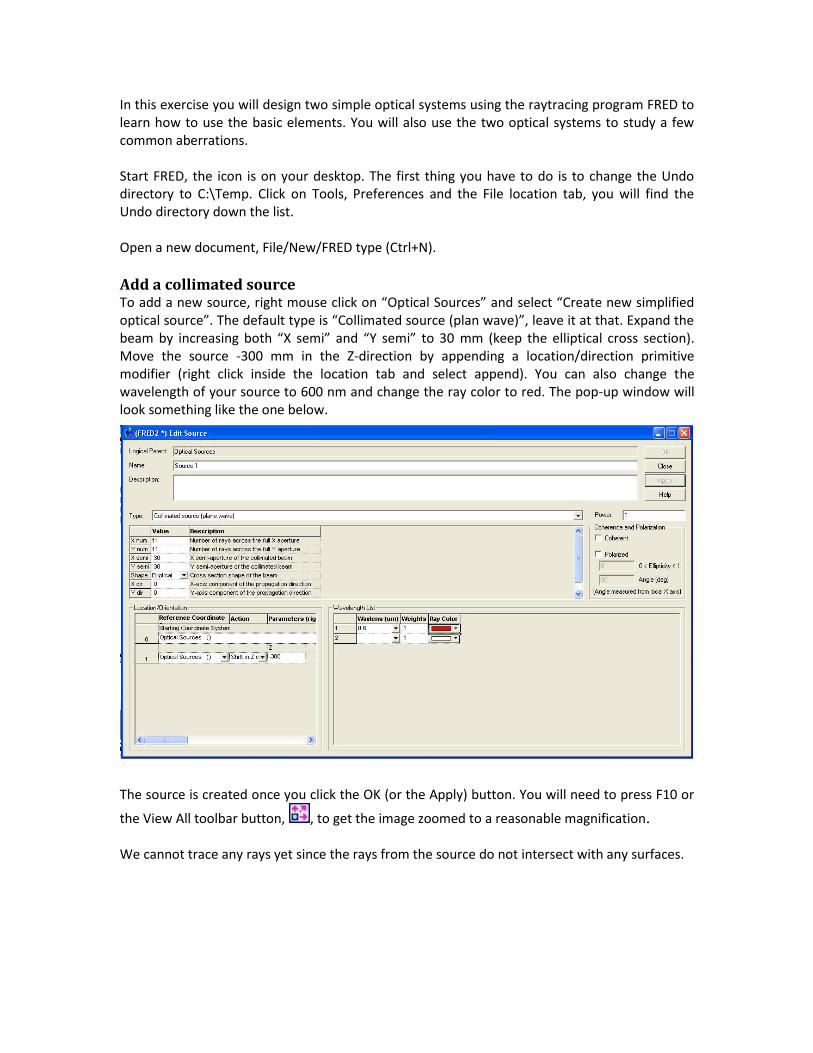
Add a collimated source To add a new source, right mouse click on “Optical Sources” and select “Create new simplified optical source”. The default type is “Collimated source (plan wave)”, leave it at that. Expand the beam by increasing both “X semi” and “Y semi” to 30 mm (keep the elliptical cross section). Move the source -300 mm in the Z-direction by appending a location/direction primitive modifier (right click inside the location tab and select append). You can also change the wavelength of your source to 600 nm and change the ray color to red. The pop-up window will look something like the one below.
The source is created once you click the OK (or the Apply) button. You will need to press F10 or
the View All toolbar button, , to get the image zoomed to a reasonable magnification. We cannot trace any rays yet since the rays from the source do not intersect with any surfaces.
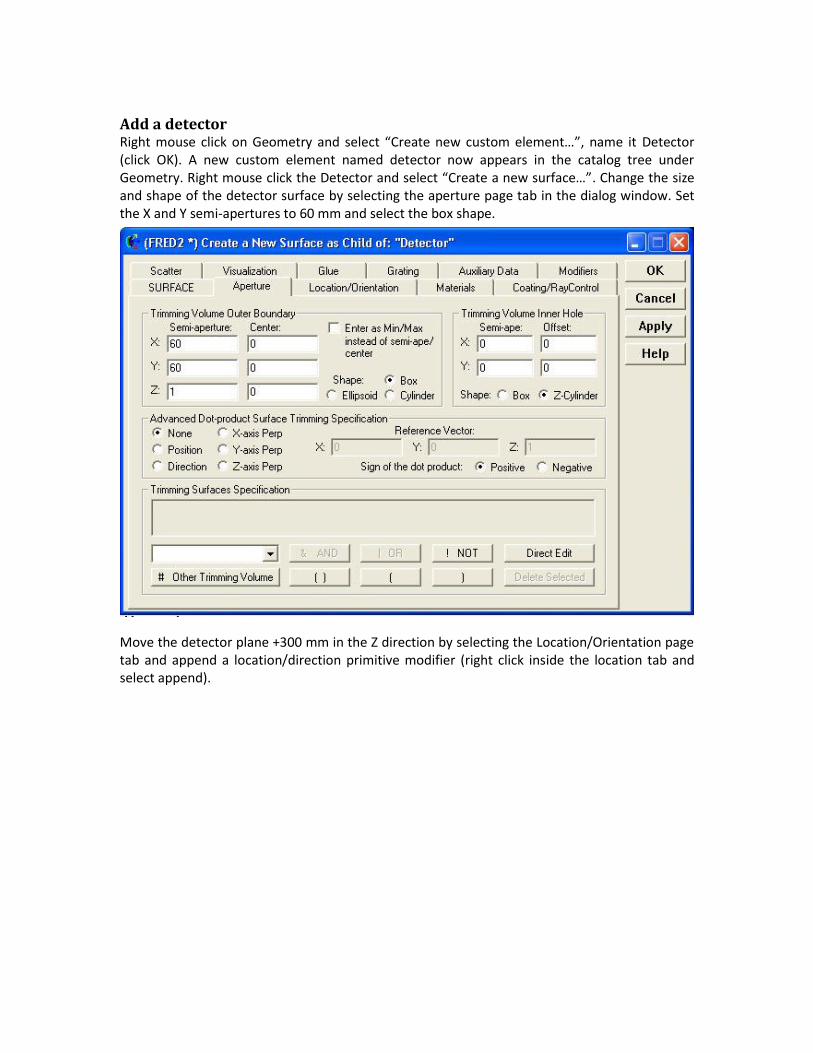
Add a detector Right mouse click on Geometry and select “Create new custom element…”, name it Detector (click OK). A new custom element named detector now appears in the catalog tree under Geometry. Right mouse click the Detector and select “Create a new surface…”. Change the size and shape of the detector surface by selecting the aperture page tab in the dialog window. Set the X and Y semi-apertures to 60 mm and select the box shape.
Move the detector plane +300 mm in the Z direction by selecting the Location/Orientation page tab and append a location/direction primitive modifier (right click inside the location tab and select append).

Raytrace We can now trace the rays since they will intersect with a surface. Select “Trace and Render” from the Raytrace menu.
Your figure will look something like:
You can zoom, translate and rotate the view using the following buttons:
To analyze the rays on the detector we have to associate an analysis surface with the detector surface. This is done in two steps: we have to create a new analysis surface and attach this surface to the detector. Right mouse click on the “Analysis Surface(s)” and select “New analysis surface…”. To attach the analysis surface to the detector we will use the “drag and drop” method, left mouse click on the analysis surface and drag it to the detector surface, this will change the location of the analysis surface to the location of the detector (if the detector is moved, the analysis surface will automatically follow). To see what the rays look like on the detector select the “Position spot diagram…” from the Analysis menu.
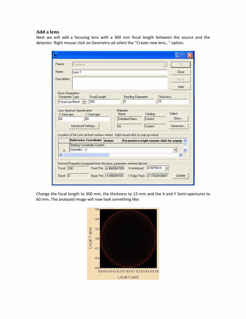
Add a lens Next we will add a focusing lens with a 300 mm focal length between the source and the detector. Right mouse click on Geometry ad select the “Create new lens…” option.
Change the focal length to 300 mm, the thickness to 15 mm and the X and Y Semi-apertures to 60 mm. The analyzed image will now look something like:

Find best geometrical focus We would like to find the convergence of the rays (best focus) and place our detector at this point. To do this we can use the “Best Geometric Focus…” option from the analyses menu. This option takes the selected rays (we will use all rays) and finds the location in X, Y, and Z where they are closest together. The result appears in the lower part of the window.
X Y Z
Best Focus: 2.12e-15 4.61e-14 307.1267364058
Copy the Z-value and place the detector at this location and analyze again, is the spot size smaller now?
Focusing with a mirror Design a new optical system and use a mirror to focus the rays from a point source onto a detector. Suggested specifications: Source: Type: Point source Angle: 5
Zones: 5 Mirror: Focal length: 300 mm Semi Aperture: 60 mm Rotation about Y-axis: 5 Shift in Z direction: 600 Detector: Shape: box Semi-aperture: 10 mm Shift in X-direction: -104 mm
Aberrations Use the two optical systems that you have just designed to study different aberration (three common aberrations can be found on next page).
1) Coma. Rotate the lens 15 degrees. How is the focus affected by this rotation? Is the focusing improved if the lens is replaced by a plane-convex lens with the same focal length?
2) Chromatic aberration. Add a second wavelength to your source in the lens system and locate the two focal points.
3) Astigmatism. Identify the tangential and sagittal foci in the mirror system. Which focus is found by the “Best Geometric Focus…” option?
4) Do you see any chromatic aberrations in the optical system with the mirror?

Aberrations Astigmatism is the elongation of an image. With spherical optics a point source will be elongated into two line images and one visibly focused “true” image. One line image will be vertical with a width close to the diameter of the point; the other will be horizontal with a height close to the diameter of the point. These images are separated in space. The elongated images fall on two focal planes, one called the tangential and the other called the sagittal.
Coma is the smearing or blurring of an image. A point source is smeared to a shape similar to a comet. The amount of smearing is a function of off-axis rays composing the image. The larger the aperture of the spectrometer the greater the coma as more off-axis rays are captured.
Chromatic aberrations arise specifically in polychromatic light. Different “colored” rays will propagate through the optical system along different paths and will therefore be focused differently. The focal length of a lens is wavelength dependent since the refractive index is wavelength dependent and different colors will be focused at different places. Chromatic aberrations can be corrected for by constructing a lens from two thin lenses made of different materials (a so called achromatic doublet) or by using focusing mirrors instead of lenses.

440 S. Williams Blvd. – Suite #106 Tucson AZ 85711 1-520-733-9557/ph, 1-520-733-9609/fax www.photonengr.com
FRED Optical Engineering Software
University Gratis License Agreement for Students The undersigned student (referred to herein as “student” or “students”) requests the use of the temporary, Gratis license of FRED Optical Engineering software. The student agrees to use FRED for instructional and educational purposes related to his optics course enrollment. The use of FRED for any other task is expressly forbidden. In particular, the use of FRED for consulting purposes, paid or unpaid, is expressly forbidden. Students may submit technical support questions to [email protected]. The student is in good standing at the Lund University and has been pre-approved by Dr. Johan Mauritsson (signature below) to participate in this University Gratis Program offered by Photon Engineering, LLC for the temporary, free use of FRED Optical Engineering Software for educational/classroom purposes. (Complete all information below, please sign and then email or fax this agreement to Photon Engineering, LLC at 1-520-733-9609 ore-mail to [email protected])
Student's Name and contact information: __________________________________________________________________________________ (Name) __________________________________________________________________________________ (Street Address – Apt. #) __________________________________________________________________________________ (City, State ZIP) __________________________________________________________________________________ (Phone) (Email) __________________________________________________________________________________ (Signature) (Date) Request Approved by :_______________________________________________________________
(Professor’s Signature) (Date) Request Processed by: ______________________________________________________________ (Photon Engineering, LLC) (Date)