operation manual - mahle service solutions | · pdf filelaser 4® laser 4 plus®...
TRANSCRIPT

Laser 4®
Laser 4 Plus®
OPERATION MANUAL
Four Wheel Alignment
RTI Technologies, Inc.
York, PA 17402800-468-2321 (Ext. 259)
Manual No. 040-80152-00

Page 1
TABLE OF CONTENTS
Four Wheel Alignment, Basics . . . . . . . . . . . . . . . . . . . 3
Pre-Alignment Checks . . . . . . . . . . . . . . . . . . . . . . . . . 4
Four Wheel Alignment Procedures
Install Wheel Clamps . . . . . . . . . . . . . . . . . . . . . 5
Compensating Wheel Runout . . . . . . . . . . . . . . . 5
Camber Reading . . . . . . . . . . . . . . . . . . . . . . . . . 7
Caster Reading . . . . . . . . . . . . . . . . . . . . . . . . . . 9
Steering Axis Inclination (SAI) Reading . . . . . 11
Instrumentation Set-up . . . . . . . . . . . . . . . . . . . 13
Front Wheel Toe Reading . . . . . . . . . . . . . . . . 14
Front Wheel Alignment to Vehicle Centerline 16
Thrust Angle Alignment . . . . . . . . . . . . . . . . . . 17
Total Vehicle Four Wheel Alignment . . . . . . . 18
Calibration Procedure . . . . . . . . . . . . . . . . . . . . . . . . . 19
Battery Replacement . . . . . . . . . . . . . . . . . . . . . . . . . . 22
CONGRATULATIONS: You have purchased one of the finest Four-wheel Alignment Systems available atany price.
Fill out and return the Warranty Card within 90 days to activate the warranty andfree lifetime technical support.
Laser 4 & Laser 4 Plus - Instrumentation Only
Factory Technical Support
( 8 AM to 5 PM Eastern )
800-468-2321
(Consult the shop manual concerning methods for making alignment adjustments.)

Page 2
The Laser 4 Plus is a four-wheel alignment system that uses three Class II laser products. These lasers have amaximum output power of 5.0 milliwatts. The laser tubes meet all government safety standards, althoughcommon sense dictates that one should not stare directly into the beam. Laser precision is unaffected by light,temperature, and the concentrated light beam is clearly visible anywhere. The following precautions have beentaken to insure the safety of the system (See Fig. 1):
1) Serial Number label is located on underside of casting on power supply cover. Each serial number isrecorded for future identification.
2) LED light comes on as soon as power is activated to laser beam.
3) Slide cover must be slid toward casting to uncover laser beam (LH Toe Gauge only).
4) Caution decals are located on the unit.
5) Flip-open protective cap protects laser unit when not in use.
CAUTION: Use of controls or adjustments or performance of procedures other than those specified hereinmay result in hazardous radiation exposure.

Page 3
FOUR WHEEL ALIGNMENTRear wheels must track and follow the front wheels ina parallel direction with all four wheel adjusted to thecommon centerline of the vehicle. (See Fig. 2)
1)Front wheel alignment andfront wheel toe on carm a n u f a c t u r e r ’ sspecifications.
2)Rear wheel alignment andrear wheel toe on carm a n u f a c t u r e r ’ sspecifications.
3)Front wheels track to rearwheel thrust lines and tocenterline of vehicle.
4)Steering wheel centered instraight ahead position.
BASIC STEPS TO DO FOUR WHEEL ALIGNMENTS
Step 1
Adjust front wheel camber and caster to car manufacturer’ssettings. (See Fig. 3)
Step 2
Center steering wheel. Adjust front wheel toe tomanufacturer’s setting. (See Fig.4)
Step 3
Adjust front wheels to rear wheel in relation to rear axleposition. (See Fig. 5)
Step 4
Adjust rear wheel camber and toe to car manufacturer’ssetting.

Page 4
PRE-ALIGNMENT CHECKSTo maintain a true alignment job; ensure maximum tire mileage and steering safety, it is important to performcertain pre-alignment checks before doing wheel alignment adjustments. They are:
1. Inflate tires to proper inflation pressures.
2. Check car spring height.
3. Check shock absorbers and struts.
4. Inspect steering/suspension parts for wear or looseness. Replaceparts which are worn beyond manufacturer’s accepted tolerances.
5. Check calibrations of the Laser 4 wheel alignment equipment. SeeCalibration Procedure section of this manual.
FRONT WHEEL SETBACKFront wheel setback is a condition in whichone front wheel has been driven or pushedback, out of alignment, from the oppositewheel. It is caused by one wheel of the vehiclestriking a curb or pothole in the road forcingthat wheel back from the other (See Fig. A).
To measure front wheel setback with the Laser4 wheel alignment system, adjust front wheeltoe; center steering wheel, and note thelocation of the Laser beam on the wheelsetback scale (See Fig. B) of the passenger sidelaser toe gauge. Make sure that the Laser toegauges are centered on the wheel clamps. Thescale reads either right or left wheel setback.The front wheel suspension should be adjustedif the setback is greater than 1/4 inch.Excessive front wheel setback will cause achange in caster.
The Laser 4 alignment system automaticallycompensates for front wheel setback becauseof the use of the tapered, precisely groundmagnets. When toe is adjusted to zero, the tubeof the optical toe gauges become parallel toeach other. Front wheel toe reading isunaffected by front wheel setback.
Page 5
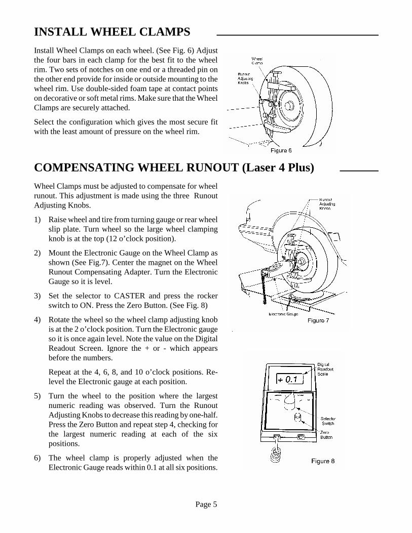
INSTALL WHEEL CLAMPSInstall Wheel Clamps on each wheel. (See Fig. 6) Adjustthe four bars in each clamp for the best fit to the wheelrim. Two sets of notches on one end or a threaded pin onthe other end provide for inside or outside mounting to thewheel rim. Use double-sided foam tape at contact pointson decorative or soft metal rims. Make sure that the WheelClamps are securely attached.
Select the configuration which gives the most secure fitwith the least amount of pressure on the wheel rim.
COMPENSATING WHEEL RUNOUT (Laser 4 Plus)Wheel Clamps must be adjusted to compensate for wheelrunout. This adjustment is made using the three RunoutAdjusting Knobs.
1) Raise wheel and tire from turning gauge or rear wheelslip plate. Turn wheel so the large wheel clampingknob is at the top (12 o’clock position).
2) Mount the Electronic Gauge on the Wheel Clamp asshown (See Fig.7). Center the magnet on the WheelRunout Compensating Adapter. Turn the ElectronicGauge so it is level.
3) Set the selector to CASTER and press the rockerswitch to ON. Press the Zero Button. (See Fig. 8)
4) Rotate the wheel so the wheel clamp adjusting knobis at the 2 o’clock position. Turn the Electronic gaugeso it is once again level. Note the value on the DigitalReadout Screen. Ignore the + or - which appearsbefore the numbers.
Repeat at the 4, 6, 8, and 10 o’clock positions. Re-level the Electronic gauge at each position.
5) Turn the wheel to the position where the largestnumeric reading was observed. Turn the RunoutAdjusting Knobs to decrease this reading by one-half.Press the Zero Button and repeat step 4, checking forthe largest numeric reading at each of the sixpositions.
6) The wheel clamp is properly adjusted when theElectronic Gauge reads within 0.1 at all six positions.

Page 6
COMPENSATING WHEEL RUNOUT (Laser 4)Wheel Clamps must be adjusted to compensate for wheelrunout. This adjustment is made using the three WheelRunout Adjusting Knobs.
1) Raise wheel and tire from turning gauge or rear wheelslip plate. Turn wheel so the large wheel clampingknob is at the top (12 o’clock position).
2) Mount the Spirit Level Gauge on the Wheel Clamp.(See Figure 9) Center the magnet on the WheelRunout Compensating Adapter. Turn the Spirit LevelGauge so it is level.
3) Zero the Caster Spirit Level using the adjusting knobon the bottom of the unit.
4) Rotate the wheel so the wheel clamp adjusting knobis at the 2 o’clock position. Turn the Spirit LevelGauge so it is once again level. Note the amount ofmovement of the bubble away from zero.
Repeat at the 4, 6, 8, and 10 o’clock positions. Re-level the Spirit Level Gauge at each position.
5) Turn the wheel to the position where the largestmovement of the bubble was observed. Turn theRunout Adjusting Knobs to decrease this reading byone-half. Zero the Caster Spirit Level and repeat step4, checking for the largest movement of the bubbleaway from zero at each of the six positions.
6) The wheel clamp is properly adjusted when thebubble does not move away from zero at all sixpositions.

Page 7
CAMBER READING (Laser 4 Plus)Camber: The inward or outward tilt of the wheel at the top
Camber is measured in degrees.
Wheel exactly vertical: Zero camber
Top of wheel tilts in: Negative camber
Top of wheel tilts out: Positive camber
A vehicle with Negative Camber is shown in Fig. 10.
Proceed with the following steps to read Camber:
1) Place front wheels in straight ahead position withsteering wheel level. The engine must be started if thevehicle has power steering. Remove locking pinsfrom the turning radius gauges and rear wheel slipplates. Rotate each wheel until the large wheel clampadjusting knob is at the top.
2) Lower all four wheels until the front wheels rest onthe turning radius gauges and the rear wheels rest onthe rear wheel slip plates. Be sure turning radiusgauges are centered under the front tires.
3) Install brake pedal depressor. The engine must berunning if the vehicle has power brakes.
4) Bounce the vehicle at both front and rear to normalizethe suspension weight.
5) Mount the Electronic Gauge on the left front WheelClamp. Be sure the magnet is centered on themounting disk (See Fig. 11).
6) Set the selector to CAMBER and press the switch toON (See Fig. 12).
7) Read Camber on the Digital Readout Scale (Anegative 0.3 is indicated in Fig. 12). The numeric readout will be preceded by a + or - to indicate positive ornegative Camber.
8) Repeat the above procedure on the right front wheel.If camber adjustments and specifications are availablefor the rear wheels, repeat the above on each wheel.

Page 8
Camber Reading (Laser 4)
Proceed with the following steps to read Camber:
1) Place front wheels in straight ahead position withsteering wheel level. The engine must be started ifthe vehicle has power steering. Remove lockingpins from the turning radius gauges and rear wheelslip plates. Rotate each wheel until the large wheelclamp adjusting knob is at the top.
2) Lower all four wheels until the front wheels rest onthe turning radius gauges and the rear wheels reston the rear wheel slip plates. Be sure turning radiusgauges are centered under the front tires.
3) Install brake pedal depressor. The engine must berunning if the vehicle has power brakes.
4) Bounce the vehicle at both front and rear tonormalize the suspension weight.
5) Mount the Spirit Level Gauge on the left frontWheel Clamp. (See Fig. 13) Be sure the magnet iscentered on the mounting disk.
6) Read Camber at the center of the bubble on theCamber Scale. The spirit level for Camber is locatedon the right side of the gauge. (See Fig. 14)
Camber is zero when the center of the bubble is onzero of the scale.
Camber is positive when the bubble is away fromzero toward the wheel.
Camber is negative when the bubble is away fromzero, away from the wheel.
7) Repeat the above procedure on the right front wheel.If camber adjustments and specifications are availablefor the rear wheels, repeat the above on each wheel.

Page 9
CASTER READING (Laser 4 Plus)Caster: The backward or forward tilt of the ball joint or strut at the top
Caster is measured in degrees:
Spindle support arm straight up and down on the true vertical: Zero Caster
Spindle support arm is tilted forward at the top from true vertical: Negative Caster
Spindle support arm is tilted back at the top from true vertical: Positive Caster
A vehicle with Positive Caster is shown in Fig. 15.
Proceed with the following steps to read Caster:
1) With the Electronic Gauge mounted on the leftfront wheel clamp, turn the left front wheeloutward at the front for a 20 degree reading on theradius gauge. (See Fig. 16)
2) Turn the Electronic Gauge so it is level.
3) Set the selector to CASTER and press the switch toON. Press the Zero Button. (See Fig. 18)
4) Turn the wheel inward at the front for a 20 degreereading on the radius gauge. (See Fig. 17) This is atotal swing of 40 degrees.
5) Turn the Electronic Gauge so it is level.
6) Read Caster on the Digital Readout Scale (A positive1.0 is indicated in Fig.18). The numeric reading willbe preceded by a + or - to indicate positive or negativeCaster.
7) Repeat the above procedure on the right front wheel.
Page 10
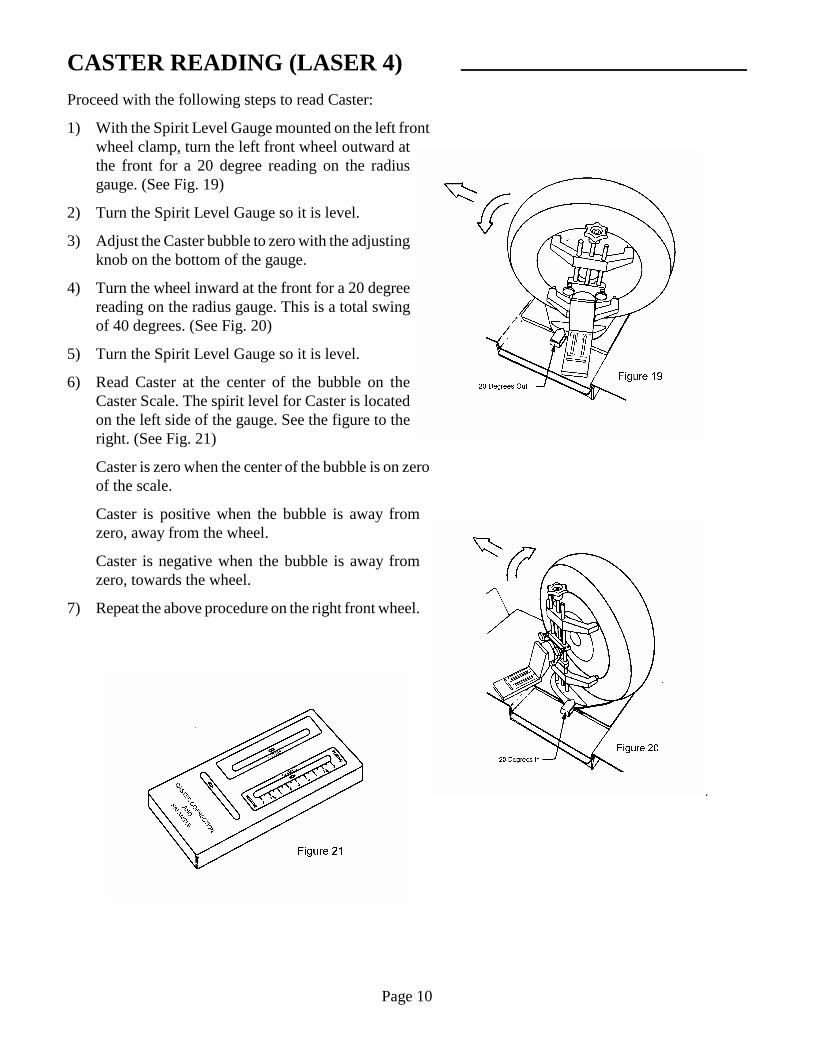
CASTER READING (LASER 4)Proceed with the following steps to read Caster:
1) With the Spirit Level Gauge mounted on the left frontwheel clamp, turn the left front wheel outward atthe front for a 20 degree reading on the radiusgauge. (See Fig. 19)
2) Turn the Spirit Level Gauge so it is level.
3) Adjust the Caster bubble to zero with the adjustingknob on the bottom of the gauge.
4) Turn the wheel inward at the front for a 20 degreereading on the radius gauge. This is a total swingof 40 degrees. (See Fig. 20)
5) Turn the Spirit Level Gauge so it is level.
6) Read Caster at the center of the bubble on theCaster Scale. The spirit level for Caster is locatedon the left side of the gauge. See the figure to theright. (See Fig. 21)
Caster is zero when the center of the bubble is on zeroof the scale.
Caster is positive when the bubble is away fromzero, away from the wheel.
Caster is negative when the bubble is away fromzero, towards the wheel.
7) Repeat the above procedure on the right front wheel.

Page 11
STEERING AXIS INCLINATION(SAI) READING
(LASER 4 Plus)SAI: The inward tilt of the ball joint or strut at the top
.
Proceed with the following steps to read SAI:
1) With the Electronic Gauge mounted on the left frontwheel clamp, turn the left front wheel outward at thefront for a 20 degree reading on the radius gauge.(Refer to Fig.19)
2) Turn the Electronic Gauge so it is level.
3) Set the selector to SAI and press the switch to ON.Press the Zero Button. (See Fig. 23)
4) Turn the wheel inward at the front for a 20 degreereading on the radius gauge. This is a total swing of40 degrees. (See Fig. 20)
5) DO NOT RE-LEVEL THE ELECTRONIC GAUGE.
6) Read SAI on the Digital Readout Scale (A positive14.5 is indicated Fig. 23)
7) Repeat the above procedure on the right front wheel.
INCLUDED ANGLEIncluded Angle: Total of the Camber and SAI Readings
Subtract negative Camber from SAI (as for the above example):
SAI 14.5
Camber -0.3
Included Angle 14.2
Add positive Camber readings to SAI: SAI 14.5
Camber +0.5
Included Angle 15.0

Page 12
STEERING AXIS INCLINATION (SAI) READING
(Laser 4)SAI: The inward tilt of the ball joint or strut at the top
.
Proceed with the following steps to read SAI:
1) With the Spirit Level Gauge mounted on the left frontwheel clamp, turn the left front wheel outward at thefront for a 20 degree reading on the radius gauge. (SeeFig. 24)
2) Pivot the Spirit Level Gauge so that the SAI bubble readszero on scale “L”. (See Fig 26)
Note: The bottom scale marked “L” is for the left wheeland the upper scale marked “R” is for the right wheel.
3) Turn the wheel inward at the front for a 20 degreereading on the radius gauge. This is a total swing of 40degrees. (See Fig. 25)
4) DO NOT RE-LEVEL THE ELECTRONIC GAUGE.
5) Read center of SAI bubble for SAI readout. (See Fig. 26)
If the SAI reading is higher than the scale on the gauge, turnthe wheel until an 8 degree reading is reached. Re-adjust thegauge for a reading of zero and continue turning the wheel.Add the 8 degrees to the final reading to obtain the actualSAI reading.
6) Repeat the above procedure on the right front wheel. Use thescale labeled “R”. (See Fig. 26)

Page 13
INSTRUMENTATION SET-UPCenter the Steering Wheel:
Center the steering wheel in the straight ahead position and clamp in place with the Steering Wheel Holder.The engine must be running to set the steering wheel position on cars with power steering.
Mount the Left & Right Laser Toe Gauges:
1) Determine the manufacturer’s preferred total toe specification for the front wheels. Rotate the taperedmagnet on each Laser Toe Gauge to one-half this specified value. (See Fig. 27)
EXAMPLE: The manufacturer’s preferred total toe specification is 0.08 inches Toe In. Rotate both ofthe tapered magnets to one-half this value which is 0.04 inches.
2) Mount the Laser Toe Gauges to the Wheel Clamps. Center the magnet on the Wheel RunoutCompensating Adapter. Connect the safety strap to the Wheel Clamp for extra protection against damage.(See Fig. 28)
3) Level the Laser Toe Gauges using the spirit level located on the top.
4) Flip the power switch to ON and open the protective covers on the laser beams.
Mount the Rear Retro-screens:
1) Determine the manufacturer’s preferred total toe specification for the rear wheels. Rotate the taperedmagnet on each of the Rear Retro-screens to one-half this specified value. (See Fig. 27)
2) Mount the left and right Rear Retro-screens to the Wheel Clamps. Center the magnet on the WheelRunout Compensating Adapter. Connect the safety strap to the Wheel Clamp for extra protection againstdamage.

Page 14
Figure 30
FRONT WHEEL TOE READINGToe: The difference in distance between the front and rear of the front wheels
Toe-in: Distance between front of wheels is less than distance between rear of wheels
Toe-out: Distance between front of wheels is greater than distance between rear of wheels
Adjust Laser Beam Mirror & Target:
The Left Laser Toe Gauge projects a laser beam onto theright mirror (A). This beam is reflected back to thegraduated toe scale on the Left Laser Toe Gauge.(See Fig.29)
Adjust the laser beam vertically to the center of the mirror(A) by using the knob (E) on the Left Laser Toe Gauge.Rotate the laser beam assembly inside the tube of the LeftLaser Toe Gauge. Re-tighten knob.
If the laser beam, reflected back from the mirror (A),doesn’t strike the graduated toe scale, loosen both knobs(R) on the Right Laser Toe Gauge (See Fig. 30). Rotate themirror housing (A) until the laser beam image strikes thegraduated toe scale. Re-tighten both knobs.
Reading Front Wheel Toe:
Read Front Wheel Toe on the graduated toe scale on theLeft Laser Toe Gauge. (See Fig. 31)
Toe is within spec if the laser beam image is in the centerof the scale at zero.
One-half of the manufacturer’s total toe specification is already dialed in with each of the magnets, so areading of zero on these scales means the toe is correctly adjusted to the manufacturer’s specification.
Figure 31

Page 15
TOE READING ILLUSTRATIONS
Page 16
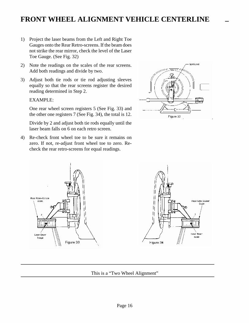
FRONT WHEEL ALIGNMENT VEHICLE CENTERLINE
1) Project the laser beams from the Left and Right ToeGauges onto the Rear Retro-screens. If the beam doesnot strike the rear mirror, check the level of the LaserToe Gauge. (See Fig. 32)
2) Note the readings on the scales of the rear screens.Add both readings and divide by two.
3) Adjust both tie rods or tie rod adjusting sleevesequally so that the rear screens register the desiredreading determined in Step 2.
EXAMPLE:
One rear wheel screen registers 5 (See Fig. 33) andthe other one registers 7 (See Fig. 34), the total is 12.
Divide by 2 and adjust both tie rods equally until thelaser beam falls on 6 on each retro screen.
4) Re-check front wheel toe to be sure it remains onzero. If not, re-adjust front wheel toe to zero. Re-check the rear retro-screens for equal readings.
This is a “Two Wheel Alignment”

Page 17
THRUST ANGLE ALIGNMENT
1) Check that both Laser Toe Gauges are level. The laser beams should be visible on the rear Retro-screenmirrors (See Fig. 35).
2) Rotate the rear Retro-screen assemblies out of level, if necessary, so that the laser beams will be reflectedback to the front Toe Gauges and be visible on the Thrust Angle Scales.
3) Note the readings on the Thrust Angle Scales. Add both readings and divide by two.
4) Adjust both tie rods or tie rod adjusting sleeves equally so that the Thrust Angle Scales register thedesired reading determined in Step 3.
EXAMPLE:
One Thrust Angle Scale registers 4 (See Fig. 36)and the other one registers 6 (See Fig. 37), the total is10.
Divide by 2 and adjust both tie rods equally until the laser beam falls on 5 on each Thrust Angle Scale.(See Fig. 39 and Fig. 40)
This is a Thrust Angle Alignment where the front wheel position is corrected for rear wheel misalignment.

Page 18
Total Vehicle Four-Wheel Alignment
1) Check that both Laser Toe Gauges are level. The laser beams should be visible on the rear Retro-screenmirrors.(See Fig. 38)
2) Rotate the rear Retro-screen assemblies out of level if necessary, so that the laser beams will be reflectedback to the front Toe Gauges and be visible on the Thrust Angle Scales.
3) Note the reading on each of the Thrust Angle Scales. Adjust the toe of each rear wheel until the laserbeam image on the corresponding Thrust Angle Scale is in the middle at the number 5. (See Fig. 39 andFig. 40)
This completes a four-wheel alignment.

Page 19
CALIBRATION PROCEDUREMount and level the Calibration Bar on Calibration Stands or the rear of the Storage Cart
Calibration of Front Wheel Toe Laser Beam (See Figure 42)
1) Rotate the tapered magnets on the Left and Right ToeGauges to zero.
2) Mount the Left and Right Toe Gauges on the ends ofthe Calibration Bar. Be sure the centers of themagnets fit over the raised machined surfaces at theends of the Calibration bar. (See Fig. 41)
3) Level both Toe Gauges and check the laser beam on the mirror screen (A). If the laser beam image is notlocated midway up on the mirror screen (A), loosen the knob (E) on the Left Toe Gauge and slide it upor down. This moves the laser beam image vertically until it is on the mirror.
4) The center of the laser beam image should be on zero on the screen (A). If not, alternately adjust Allenset screws of the laser diode bulb retainer on the Left Toe Gauge until the center of the beam image readszero on the Right Toe Gauge screen (A).
There are four Allen set screws on the laser diode retainer. The top and bottom set screws (D) control thevertical movement of the beam image. The left and right screws (B) control side-to-side movement ofthe beam image.
5) Adjust the mirror (A) up or down as required so the reflected laser beam image is on the front toe scale.Loosen knobs (R) to make any required adjustments.
6) Adjust Allen set screws (F) until the center of the laser beam image reads zero on the front toe scale (C).

Page 20
CALIBRATION PROCEDURE
The Gauges are now parallel - “Toe reads zero”
Calibration of Right & Left Toe Gauge Laser Beams
1) Rotate all tapered magnets on the Toe Gauges andRear Retro-screens to zero
2) Mount the Left Toe Gauge and Left Retro-screen tothe machined surfaces on the side of the CalibrationBar. (See Fig. 43)

Page 21
CALIBRATION PROCEDURE
Calibration of Right & Left Toe Gauge Laser Beams (continued)
3) Level the Toe Gauge and project the laser beamimage on the rear Retro-screen. (See Figure 44) Thecenter of the beam image must be on 6 and midwayup the mirror. If not, alternately loosen and tightenAllen set screws on the laser diode retainer.
There are four Allen set screws on the laser dioderetainer. (See Figure 45) The top and bottom setscrews (D) control the vertical movement of the beamimage. The left and right screws (B) control side-to-side movement of the beam image.
4) Check the location of the reflected laser beam imageon the Thrust Angle Scale on the Laser Toe gauge.
With the Rear-retro Screen level, the center of theimage should be mid-way up and on 5 on the ThrustAngle Scale.
If not, adjust the two screws (M) (See Fig. 44) untilthe image is on 5 and adjust screw (L) until the imageis mid-way up on the Thrust Angle Scale.
5) Remove the Left Toe Gauge and Left Retro-screen.Mount the Right Toe Gauge and Right Retro-screenand repeat steps 1 through 4.
The Retro-screen is now at a perfect 90 degree angle to the front Toe Gauge and the laser beam imageindicates zero toe on the Thrust Angle Screen.

Page 22
BATTERY REPLACEMENTThe Laser 4 is powered by eight “C” batteries; four batteries located in each Toe Gauge. Alkaline batteriesare recommended for extended life.
The batteries should be replaced when the laser beam image becomes dim or can no longer be seen.
To replace the batteries (See Figure 46):
1) Flip the Laser Toe Gauge switch to OFF.
2) Place the Laser Toe Gauge on a workbench with the underside of the casting facing up.
3) Loosen the battery cover locking knobs and open the cover.
4) Replace the batteries following the diagram in the battery holder. Flip the switch to ON to be sure thelaser diode operates. Flip the switch to OFF.
5) Close the cover and secure with the battery cover locking knobs.