operating manual and parts lists
TRANSCRIPT

JKS WINKIE DIAMOND DRILL Page 1
OPERATING
MANUAL
AND
PARTS LISTS
Revised December 2006 Revised October 2008 Revised January 2011 Revised June 2013
JKS WINKIE DIAMOND DRILL Page 2
MANUAL
WINKIE DRILL 4
DESCRIPTION OF WINKIE DRILL 5
APPLICATIONS 5
LIMITATIONS 5
COMPONENTS OF THE WINKIE DRILL 5
BRIEF HISTORY OF DIAMOND DRILLING 6
TECHNICAL INFORMATION 7
DRILLING PROCEDURE 7
TROUBLE INDICATORS 8
ROTATIONAL SPEED VERSUS LINEAL TRAVEL 9
WATER REQUIREMENTS FOR DIAMOND DRILLING 10
UNIPRESS 10
METHODS OF ANCHORING DRILL 10
WINKIE DRILLING TOOLS 11
ADAPTERS 14
OPERATING INSTRUCTIONS FOR YOUR WINKIE 15
... WINKIE CARE AND MAINTENANCE 17
ENGINE MAINTENANCE 17
FUEL MIX AND BREAK IN 19
WINKIE DRILL PARTS LIST 20
WINKIE DRILL PARTS MANUAL 22
ENGINE STARTER 29
ENGINE IGNITION 30
ENGINE CARBURETOR 31
ENGINE POWER HEAD 33
WINKIE OPERATING MANUAL 34
ADDITIONAL DRAWINGS 37
HOW TO ORDER 44
GENERAL TERMS AND CONDITIONS 45

JKS WINKIE DIAMOND DRILL Page 3
GW-15
WHEN ORDERING PARTS PLEASE GIVE:
1. Model of Drill
2. Part Name of Part
3. Catalogue Reference Number
4. Quantity Required
5. When ordering parts for
engines, pumps, winch, etc.,
always include the PART
NAME and the NAMEPLATE
READING of the unit
6. Shipping instructions
Order by Email from
Sales Terms INCOTERMS2000 EXW Burlington ON Canada
Freight : Extra to destination (can be estimated and included)
Taxes if applicable : Extra
FOB Point : Burlington, Ontario, Canada
Delivery : Delivery date to be estimated at time of quotation
Payment Terms: Terms to be stated on quotation
Payment By: Bank Transfer to Canadian Bank (details to be supplied)
Currency: Usually Canadian Dollars or United States Dollars
Viability of Quote Prices are valid for ninety day from date of Quotation
Shipping Specs : Depending on quantities of drill material ordered with the drill.

JKS WINKIE DIAMOND DRILL Page 4
MANUAL WINKIE: THE MOST OUTSTANDING BUY IN ITS FIELD: Meet a pint-size powerhouse, driller's drill, ready to rewrite your footage costs with its nine (9) outstanding features. Lower Maintenance - Maintenance costs are reduced over the conventional core drill, resulting from minimizing the moving parts, and having only three precision machined analoy castings in the drill itself. Lower Moving Costs - Set up and moving costs are very low. Savings may be made with carrying the Winkie Drill to the site, in lieu of building roads. Lower Labor Costs - Labor cost may be cut by 50% through using only one man to operate the Winkie. Save by not building roads for the portable carry-in-hand Winkie. Lower Fuel Costs - Fuel consumption under full load is approximately 3 or 4 gallons per drilling shift. Lower Diamond Bit Costs - Dynamic balance in this dri11 means less rod vibration; thus, less drill rod and corebarrel wear, and most important, LESS DIAMOND BIT COST. High R.P.M. - High Speed bit rotation plays a very important role in reducing bit cost, in addition to yielding a greater daily footage. Diamond wear is reduced as speed of rotation approaches 700 RPM, above 700 RPM, and up to the Winkie Speed of 2000 RPM. Less Handling of Tools - The overhead principle drive on the Winkie allows as great as 3 foot runs without re-chucking on the drill rod. Compare chucking time of 36 inch strokes for the Winkie, against conventional drills with 24 inch strokes. Less Water Required - Drilling with the minimum water requirements is the best policy with the Winkie. Experience - No experienced Diamond Drill Operator is required. A minimum of instruction is required. Plus these added features:
Full 10 H.P. 2 cycle gasoline engine. 6000 RPM.
Torque resolving safety clutch
Built-in water swivel with adjustable packed type water seal.
Vacuum carburetion system to allow continued operation of the engine at any conceivable angle. Circular holding ring (for protection of the unit and complete selection of gripping areas.). Hardened spur gears for quieter, smoother and longer operation.
Water-cooled gear box.
Recess mounted bearings designed with a safety factor of "3".
Unipress mechanical pull down pressure feed.

JKS WINKIE DIAMOND DRILL Page 5
MANUAL
DESCRIPTION OF WINKIE DRILL The Winkie drill is a lightweight portable core drill. The drill was designed to recover 1" cores to a depth of 450'. In some formations, cores up to 2 1/8" in diameter can be recovered to lesser depths. A lightweight water pump is used to circulate water to remove the cuttings and to cool the bit. Diamond core bits specially designed or selected are used to cut the rock. In some softer overburdens, drag bits can be used to put the hole down to solid material. APPLICATIONS The principal applications of the Winkie are:
1. Exploration - core samples desired for mines or quarries. 2. Probing - to find depth to rock for foundation or other testing. 3. Highway Sampling - concrete cores recovered for testing pavement. 4. Masonry Drilling - cutting holes through reinforced concrete, brick; for conduits, pipes,
etc. used by public utilities, industrial plants, refineries, maintenance work, etc. 5. Grout Holes - Drilling holes for the purpose of grout injection. After the grouting has
been completed, a series of holes can be drilled to produce cores showing the effectiveness of the grout.
6. Marine Blast Hole Drilling - in certain applications, due to its portability and principal overhead direct drive the drill can be operated from an inexpensive boat or raft.
7. Underwater Drilling Remember, the Winkie Drill is the smallest and lightest weight patented gear shift drill of its
type on the world market. LIMITATIONS The Winkie drill cannot be used to produce cores in gravel, sand or silty clay formations. It is not designed to compete against jack hammers for production drilling. Its principal application is where cores are primary and hole is secondary. However, in some cases, such as drilling holes for parking meters, the hole can be drilled to required diameters. With jack hammers, a rough hole by comparison is drilled. As you see the Winkie work, more ideas for its application will be uncovered. COMPONENTS OF THE WINKIE DRILL The drill itself consists of 3 assemblies: (1) Engine (2) Transmission (3) Unipress 1. Engine - 10 HP, 2 cycle, air cooled gasoline engine. Easy starting with a nylon cord recoil type starter. A vacuum carburetor system allows drilling "up" holes or at any angle. The engine is mounted with its drive shaft vertical so that it drives directly into the transmission.
JKS WINKIE DIAMOND DRILL Page 6
MANUAL
2. Transmission Assembly - The transmission contains the clutch, gear box and water swivel. The
engine shaft, through a splined connection, drives the centrifugal clutch. As the engine speed is
increased past 900 RPM, the clutch shoes are thrown out and engage the clutch drum which rotates the
input shaft to the gear box. If the engine speed should be reduced to lower than 900 RPM, the springs on
the clutch shoe will pull the shoes away from the inner drum surface and, of course, power to the drill
rods is removed.
3. Unipress - The Winkie Unipress enables the operator to exert a steady pressure with a minimum of
exertion. Fatigue of the operator is reduced by 50% or more, contributing to more economical operation.
4. Water System - Circulating water through the drill rods down to the bit is required to wash out
cuttings, cool the bit, and to keep the core from sticking. For this purpose, an engine-pump unit
complete with hoses and water by-pass system is offered.
The pump is a JKS - BRONCO "8" - 7/8 stroke 1-1/2" bore - two piston progressing cavity positive
displacement 8.2 U.S. GPM at 400 PSI. Since the pump runs constantly with the engine, a pressure
valve relieves pressure on the pump, if for any reason the bit or rods become clogged.
A 3/4" x 20' 4-ply pressure hose with fittings and shut-off valve, and a 1" x 15' 3-ply suction hose with
fittings, foot valve and strainer are part of the water system unit.
Of course, a water supply is necessary. For masonry drilling, city water pressure is convenient. For field
work, it may be necessary to use a water tank or drum for the water. If the formation is solid enough, it
may be convenient to recirculate the water from the hole to the tank. In this case a "T" joint on top of the
casing is required to direct the water to the tank.
BRIEF HISTORY OF DIAMOND DRILLING
Modem Diamond Drilling dates back to the year 1862 when a Swiss, named Jean Rudolphe, gave birth
to the idea of mounting diamonds in the periphery of a tube to cut a cylindrical core of rock. Even before
this time, recorded history shows that as far back as 2000 B.C., the ancient Egyptians were using tubular
drills to assist in building their pyramids.
The first steam-powered drill was built in 1862-63. By 1870, steam drills with RPM as high as 360 and
5 to 7 horsepower were being used. Through the years, marked improvements have been made in
Diamond Drills and their accessories, paralleling the ever-increasing need for rock sampling in hard
formations.
The introduction of the Winkie Drill was a major step in Diamond Drill development. It offers, for the
first time, portability with Winkie drilling capacities, presently associated with drills ten times the
Winkie's weight. But the Winkie costs only a fraction of other drills.
JKS WINKIE DIAMOND DRILL Page 7
MANUAL
To get better core recovery in soft formation, it is a known fact in the Diamond Drilling Industry that larger diameter holes have to be drilled. However, the Winkie Type Drill, with its high RPM and faster penetration using less circulating water, has proven to be the first in various fields to get a larger percentage of core recovery, drilling smaller diameter holes than the conventional
drill. For instance, on one drilling project using conventional Diamond Drills, the core recovery in the coal seam was practically nil using double tube core barrels. The Winkie Drill was used on the same project with a single tube core barrel. It recovered 29-3/4" of coal cores from a 32" seam. The standard Diamond Bit sizes used are the following: **IEW (1-1/2" diameter hole – 7/8 " core) **IAW ( 1 3/4" diameter hole – 1 1/8” core) **JKT-48 (1-7/8" diameter hole - 1 3/8" core) **JKS designed a Thin Wall mining series bits hole as the "W" series to produce a larger diameter core. The mining series Thin Wall Diamond Bit allows faster penetration and uses less water to wash up less sludge. The automatic safety clutch on the Winkie Drill permits the use of thin wall bits to be run with a minimum supply of water without the worry of burning an expensive Diamond Bit.
TECHNICAL INFORMATION DRILLING PROCEDURE First of all, drill must be securely anchored. Starting the Drill Hole Starting on Rock Surfaces:
A. Use a short core barrel ranging between 1-1/2" to 2, often termed the starting barrel. This barrel is a single or double tube barrel. Drill the starting barrel at least 4" to 6" into the rock.
B. If using a whole stone straight wall bit (a bit without a core spring), dry block. Dry blocking with impregnated bit will significantly reduce bit life.
a. Shut off the water supply and b. Run the drill at half throttle, at the same time applying pressure to bit. c. The machine will automatically stop when the bit has dry blocked (wedged the
core in the face of the bit with rock dust). With a core spring, the bit may be drawn off bottom and the core will remain in the barrel. In the event the core may be left in the hole, a core fisher with springs is attached to the core barrel to fish the lost core. Do not rotate the core fisher.

JKS WINKIE DIAMOND DRILL Page 8
MANUAL
Starting with Soil Overburden:
i. The soil must be stabilized either by casing or drilling mud preceding the initiation of core drilling. Casing may be either drilled into the soil or driven until it is well seated into the rock.
ii. Assuming casing has been advanced to rock surface, the casing must be well cleaned out to free it of all foreign matter (mud, gravel etc.) except water. This is accomplished by a chopping and washing or fishtailing procedure.
A tungsten carbide drag bit, adapted directly to the drill rods, can be used to put down a pilot hole with the WINKIE, and give the operator an estimate on the depth of overburden and amount of casing required to case the whole to solid formation. After a solid formation with the drag bit, adapt the diamond or tungsten carbide casing shoe to the casing and repeat the same operation, as when drilling with drag bit but use the casing and rotate it down the pilot hole made with the drag bit. When this performance is completed, adapt the core barrel with diamond and reaming shell to dri11 rods and start coring. It is also possible to adapt the diamond or tungsten carbide casing shoe to the casing and rotate the casing into solid formation without a pilot hole. When solid formation is encountered, just leave the casing in the hole as the core barrel will pass through the casing shoe. If core recovery is required in soft shale formation, a tungsten carbide core bit can be used as well as a large stone diamond bit. It is not possible to take a core in clay, sand or gravel, and never attempt to use a diamond bit in the above formations as it will wear and destroy any expensive diamond bit.
iii. Now, lower the tools to the bottom of the hole in this order: a. Diamond bit and reaming shell b. Core Barrel c. Drill rod or rods
iv. Connect the Winkie to top of the drill rods and follow the drilling procedure as outlined in
steps A, B and C in the discussion preceeding on starting on rock surfaces.
TROUBLE INDICATORS Blocked Bit The drill engine automatically slows down, indicating that the core barrel should be withdrawn and the core emptied. Blocked Core Barrel A blocked bit usually shows itself by first a refusal to penetrate and secondly a bumping of the tools as they rotate, commonly called a "kick".
JKS WINKIE DIAMOND DRILL Page 9
MANUAL
NOTE: One of the best methods to gauge the rate of penetration is to mark the drill rods with drillers' chalk when the drill rod rotates, these rings will disappear below the collar of the hole as the bit penetrates. Always keep very close record of measurements. This is important to your logging procedure. NOTE: If drilling is continued when the core barrel is blocked, it ordinarily results in grinding of core, in turn, causing a decrease in core recovery and excessive wear on the diamond bit. Continued Blocking of the Bit A. Check to see that a free flow of water is reaching the bit. Often times the drill rods are obstructed with clay, gravel, etc. Also check your diamond bit for inside gauge. It is possible the used bit may cut a larger diameter core than the core barrel will admit. B. Possibly an insufficient water pressure is being used. Refer to the pumping chart to establish volumes for various size drill holes. In order to attain these volumes, a positive pressure must be maintained. C. Dented or bent inner tube can cause blocking. Causes of Vibration (Not necessarily in order of importance) 1. Lack of rod grease. 2. Excessive feed rate or pressure. 3. Drilling over or grinding core. 4. Incorrect water pressure and volumes. 5. Bent rod drills. 6. Incorrect size of rods and core barrels in relation to the size of the hole. 7. Drill bits too dull. ROTATIONAL SPEED VERSUS LINEAL TRAVEL Do not confuse RPM with the actual lineal travel of a diamond. A diamond on the outside cutting edge of an EW (1-1/2"dia.) bit at 1000 RPM travels 393 feet per minute. AW (1-3/4" dia.) bit has a peripheral speed of 491 feet per minute. A BW (2-3/8" dia.) bit has a peripheral speed of 622 feet per minute. A 6-1/2" dia. bit has a peripheral speed of 1636 feet per minute. When a diamond bit is not in use, protect it and do not use it as you would a hammer; it is valuable and will serve you better if used properly. Never drop your rods on the bottom of the drill hole; this could severely damage the diamond bit. Fill the hole with water before lowering.
When changing from old to new bits, use caution in lowering the rods in the hole, and it is a
good practice to ream the last two or three inches, just in case the old bit lost some gauge
which would cause a new bit to get wedged and also damage outside stones. Never wrench
your drill rods down a tight hole. This is bound to damage the outside diamonds on the
JKS WINKIE DIAMOND DRILL Page 10
MANUAL
WATER REQUIREMENTS FOR DIAMOND DRILLING
A continuous flow of water is necessary to keep the diamonds cool or from polishing: also to remove the cuttings, and to keep the core from sticking in the core barrel. A rising current of 12 inches to 18 inches per second in the hole is usually sufficient. To maintain this latter figure requires about 120 gallons per hour in an EW hole(1-1 /2" dia.); 200 gallons in an AW hole (1-7/8"dia.); 430 gallons in a BW hole 2-3/8"dia.) using (EW), (AW) and (BW) drill rods. The volume of water required in normal rock drilling ranges from about two gallons per minute using XRW rods cutting a 1-1/4" dia. hole, and water pressure required from 80 lbs. to 120 lbs. Had rock formation will consume less water than soft rock formation. Always make certain to flush and clean out the bottom of the drill hole before starting to rotate the drill rods. This is always good practice and will increase your daily footage as well as giving a better percentage of core recovery. A constant flow of water through the bit is required at all times whether using a diamond bit, drag bit, a chopping bit or wing type bit. UNIPRESS To anchor unipress, drill hole the same diameter as your split wedge bolt or bolts, approximately 5" deep, then tighten the nut to secure split wedge bolt. You are now ready to place your unipress on top of the same. Then tighten the second nut to secure the base to split wedge bolt or bolts. To drill angle holes, use portable protractor with level bubble. Position the protractor on the guide rod. Loosen the two nuts on guide bar hinge bolts and tilt unipress until level bubble comes to rest at desired angle; tighten both nuts and adjust back stay to maintain proper position. METHODS OF ANCHORING DRAW DOWN CHAIN "Dead Man" Installation Dig a hole adjacent to the boring or casing to a depth where sound soil exists. At this depth undermine the hole. Place a cross bar parallel to ground surface in the undermined hole such that when it is lifted up, it butts against sound soil. Attach a chain of sufficient length to this bar to tie down the unipress. Now, fill this hole and tamp the soil such that you have constructed a "dead man" anchor. Truck or auto Plate Method By using a plate of 10" wide x 36" long x 1/2" thick, a vehicle can be driven on this plate such that the weight of the vehicle will "anchor" the unipress. (Which is bolted to the plate).
JKS WINKIE DIAMOND DRILL Page 11
MANUAL EYE BOLT OR ANCHOR BOLT The eye bolt is a recoverable split type wedge anchor to secure the base of the drill to allow the operator to exert a pull down force on the cutting tool. Eye bolts come in various sizes. For example, for the EW Core Barrel, use 1-1/2" OD eye bolt. Always use same diameter eye bolt as core barrel. To secure the eye bolt, drill a hole approximately 5" deep, approximately 8" distance from the exploration hole to be drilled; put the eye bolt into the drilled hole then tighten nut on top to secure the same. SOILS ANCHOR The eyebolt must be replaced by a soils anchor when starting holes in overburden and no outcropping of rock is available. The soil anchor can be turned into the soil by hand or with a wrench, same as an auger. It is complete with chain. WINKIE DRILLING TOOLS Masonry Drilling - For masonry drilling, the drill string used is much simpler. This string consists of the Winkie, a sub and the masonry bit. The sub is AW box to 1-1/4-7 thread pin, the box thread on the masonry bit (2" to 6-1/4" dia.) is 1-1/4-7 thread. The core barrel of the masonry bit is an integral part of the bit and is usually 12" long; however, they can be purchased in 18" or 14" lengths or longer at extra cost. "W" SERIES ALUMINUM DRILL ROD JKS aluminum rods are manufactured from a high quality seamless aluminum tubing and the couplings are made from alloy steel. JKS aluminum rods have the following advantages compared to steel rods; less than half the weight, easier handling, faster lowering and hoisting, increase drill capacity, increased production and lower transportation costs. JKS "W" series aluminum drill rods conform to DCDMA. CDDA and BSI standards. ROD SIZES EW and AW are specified for diamond drilling and refer to the outside diameter. EW AW
Rod O.D. Inches 1 3/8 1 3/4
mm 34.9 44.
Coupling I.D. Inches 7/16 5/8
mm 11.1 15.9
SQ. Thread per Inch 3 3
Five foot (1.52m) aluminum rod and steel coupling Pounds 5.5 7.5
Kg. 2.5 3.4
JKS WINKIE DIAMOND DRILL Page 12
MANUAL
STEEL DRILL RODS
ROD SIZES EW, and AW are specified for diamond drilling and refer to the outside diameter. EW AW
Rod O.D. Inches 1 3/8 1 3/4
mm 34.9 44.
Coupling I.D. Inches 7/16 5/8
mm 11.1 15.9
SQ. Threads per inch 3 3
Five foot steel rod and steel coupling coupling
Pounds. 17.5 21.7
Kg. 8.0 9.8 DIAMOND BITS Mining series - All types of mining series bits are available. See Bit Section.
Reaming Shells - The Reaming shell is used between the core barrel and the diamond bit to maintain the gauge of the drill hole. See Bit Section. Masonry Bits - Masonry thinwall diamond bits are identified by nominal O.D. (inches); sizes up to 14" diameter are available and are complete with 12" long core barrel (or longer on request at extra cost). These bits are designed to drill through plain or reinforced concrete. They have a very narrow Kerf which minimizes the amount of concrete to be cut. A narrow Kerf bit is also a faster penetrating bit. Bit Salvage - All Surface Set mining series bits and resettable masonry bits may be returned for salvage. The customer is given credits for any diamonds which are still useable against the purchase of new bits. In other words, the customer is only charged for those new diamonds needed plus the resetting charge. TUNGSTEN CARBIDE CASING SHOE AND CASTING BIT The casing shoe is attached to the bottom of the casing and is used to drill through soft overburden until bedrock is reached. The diamond core bit will pass through the casing shoe so that there is no need to pull up the casing until the hole is completed. The tungsten carbide casing bit will not allow the core bit or reaming shell to pass through. The casing shoe has a narrow Kerf to be used for generally soft overburden. The casing bit has a wider Kerf and will take greater punishment drilling through boulders and hard pan encountered in the various types of overburden. Tungsten carbide coring bits can only be used in very soft formations. Diamond set casing bits are recommended for hard formations.
JKS WINKIE DIAMOND DRILL Page 13
MANUAL CROSS CHOPPING BIT The chopping bit is adapted to the drill and is used to clean out the inside of the casing before using the diamond bit and also to chop out any core left in the hole that cannot be fished out with the core picker. Any loose material in drill holes should be cleaned out before using a diamond bit. This method will give the diamond bit greater drilling life. DG TUNGSTEN CARBIDE DRAG BIT This bit is adapted to the drill rods and will drill through any soft formation such as clay and shale when core recovery is not required. It can also be used for probing to determine the depth of overburden but must be used with water circulating through it at all times. HOISTING EQUIPMENT LOWERING IRON This is an eccentric clevis with a 5" handle attached. When placed over the drill rods, it will hold the rods in position for adding lengths when lowering into the hole. COM-A-LONGS (Pipe Wrenches) These are best explained as open-type simple wrenches and are used to get better leverage when pulling drill rods out of the hole; also to protect the surface of the drill rods. Light weight aluminum pipe wrenches with hardened steel gripping teeth are available. PIPE PIN TO CASING PIN To recirculate and save on water consumption, the adapter is installed to the top of the casing, after bedrock has been reached, and a pipe T is used. EW to 1-1/2" pipe, AW to 2" pipe, and BW to 2-1/2" pipe. ADJUSTABLE PIPE TONGS The adjustable tongs are used when withdrawing the drill rods from the hole. They can be locked in any position, suspending the rods and preventing them from dropping back down the hole.

JKS WINKIE DIAMOND DRILL Page 14
MANUAL
ADAPTERS ROD BOX TO CASING PIN Sub used to connect the casing to the drill rods.
AW ROD BOX TO BW ROD PIN Required when using AW drill rods and a BW core barrel.
AW BOX TO 1-1/4" - 7 THREAD ADAPTER This adapter is only required to connect the masonry thin wall bit to the Winkie Drill. AW ROD
PIN TO EW ROD PIN SUB OR AW ROD PIN TO BW ROD PIN SUB
This sub is used to reduce the size from the Winkie AW box to the smaller drill rods and core barrels such as EW; also to larger drill rods. It is attached directly to the Winkie box output shaft (drive chuck). FISHING TOOLS
ROD AND COUPLING RECOVERY TAPS
Used when drill rod or couplings break in the drill hole. It is a tapered and threaded tool that is attached to the drill rods and lowered into the hole. Turn the upper string of rods with a wrench, until the tap is secured firmly into the broken lower string of rods, then withdraw the complete string of drill rods.
CORE LIFTER CASE AND CORE LIFTER
Required on all "I" series and JKT 48 swivel type core barrels. This item must be attached to the end of the inner core tube to keep the core from falling out of the core barrel when withdrawing the rods from the drill hole.
JKS WINKIE DIAMOND DRILL Page 15
MANUAL
OPERATING INSTRUCTIONS FOR YOUR WINKIE
The Winkie Diamond Drill is designed to give you the most in drill performance and economy.
Engine care and operation:
The Winkie Drill is powered by a 10 HP, 2 cycle, air cooled, high speed gasoline engine. If the following instructions are carefully observed, you may be assured of dependable and long service. "IMPORTANT" Fuel: Refer to Plate #1619B on fuel When operating in extreme cold weather you may add one pint of diesel fuel oil to one gallon of your regular Winkie Mix. As above item B explained, this will eliminate the engine stalling due to the non-detergent oil congealing in the carburetor.
Starting Engine:
1. Make sure fuel is at carburetor by using hose pump.
2. Move choke lever to choke position (move towards the air filter).
3. Open throttle wide.
4. Crank the engine by pulling the recoil starter handle. A short, quick pull, allowing no more than two (2) feet of rope to be exposed assures quicker and easier starting plus greater starter life. In very cold weather, or if the engine has not been run for a long period, two or more pulls may be necessary. After the engine starts, gradually move the choke lever back until engine has warmed up. When starting a warm engine, choking is not necessary. Choking a warm engine or excessively choking a cold engine can cause flooding. If this occurs, continue cranking engine until it starts, with the choke pushed open and the fuel line disconnected.
Stopping Engine: Press the “Kill Button” or close the choke to stop the engine. Muffler and Exhaust Ports: The muffler and the exhaust ports should be cleaned every fifty (50) hours when the engine is running under continuous full load conditions. Clean every one hundred (100) to one hundred (150) hours when the engine is under light load. Clean exhaust ports if the engine loses power.
JKS WINKIE DIAMOND DRILL Page 16
MANUAL Cleaning Engine: To clean the cylinder exhaust ports, remove muffler and spark plug, then turn the starter pulley so that the piston is at the bottom of stroke, below the exhaust holes. With any blunt instrument, scrape the carbon from the three ( 3) cylinder holes so that they are completely open and remove the carbon from the surrounding exhaust chamber. Crank the engine several times to blow out the loosened carbon. Replace the spark plug and muffler. Throttle Linkage: For proper engine operation, throttle linkage, and carburetor throttle shaft and spring, must be free of all foreign material. Check each time the engine is used and clean if necessary. Carburetor Adjustments: These three (3) adjustments are on the carburetor:
A. High speed at full load adjustment, marked by a stamping on the carburetor housing with the letter "H".
B. Low speed (no load) adjustment, marked by a stamping on the carburetor housing with the Letter "L".
C. Idle speed adjustment, merely is an adjustable set screw to increase, or decrease the distance the carburetor throttle shaft may travel.
High Speed Adjustment: This was previously referred to as the full load adjustment. This has been properly adjusted before leaving the factory and should not be tampered with needlessly. When attempting an adjustment, do it while drilling at full throttle. To adjust the engine, the unit must be under load. This adjustment may be made by ear. Rotate the adjustment screw slowly first to the left, then to the right until the engine speeds up and runs at the smoothest tempo. Do not run with screw less than one (1) full turn open. If screw is less than (1) full turn open the proper amount of lubricant cannot enter.
For normal operation use one and one half (1-1/2) turns.

JKS WINKIE DIAMOND DRILL Page 17
MANUAL WINKIE DRILL CARE & MAINTENANCE CAUTION: Before operating the drill or starting the engine, fill the gear case with Shell Tellus #69 or equivalent high speed transmission oil. Capacity of the gear case one (1) quart. With temperature of less than 40 degrees F. it may be necessary to thin the oil with any good SAE 30 weight oil. In unusual circumstances when the aforementioned oil is not readily available use SAE 40 weight oil in plus 40 degree F. temperatures, and SAE oil in minus 40 degree F. temperatures. Fill the gear case so that the oil just runs out the filler hole when the drill is held in upright position.
A. Tighten all nuts and screws after the first eight (8) hours of use. Repeat this tightening of all nuts and screws after each fifty (50) hours of operation or as needed.
SAFETY NOTE Never attempt to add or take off drill rods while engine is idling. If in doubt about any operation STOP AND THINK! ENGINE MAINTENANCE Spark Plug: (AC 44F, Champion L90C, NGK B5HS) Check plug periodically. Oily or carboned plug causes starting difficulty. Some plugs may operate hours and then prove defective requiring replacement. The spark plug should be cleaned, and the points set at .030 inches. If there is any doubt of the condition of the plug, it should be replaced with original equipment. (Same type) Air Filter: Replace when necessary. Low Speed Adjustment: This again has been set at the factory and need not be tampered with unless deemed absolutely necessary. When an adjustment is necessary, run the machine at an idle without load, adjusting in the same manner as the High Speed Adjustment. Adjustment should be normally one and quarter (1-1/4) turns for low speed. Idle Speed Adjustment: This adjustment may be governed to suit an individual's preference.
JKS WINKIE DIAMOND DRILL Page 18
MANUAL
NOTE: Two cycle engines, when running under light loads, may appear to miss. This in no way
affects the operation of the engine.
Should Engine Fail to Start:
A. Check for fuel in the fuel tank and check to see that the valve is open. B. Check for spark; remove spark plug and, with magneto wire attached, hold the base of
the plug against the engine, crank engine. A spark should jump across the plug points. If it does not, clean the plug or replace
C. with a new one. D. Check magneto; hold the spark wire 3/16" from engine, spark should jump from the
terminal to the engine when cranked. If no spark occurs, test the condenser and coil. If faulty, replace.
E. Check for flooding. Remove spark plug and if plug is wet or if gap is closed by liquid fuel, the plug should be dried and with shut-off valve closed the engine should be cranked until vapor stops coming out of spark
F. plug hole. Re-insert plug and open shut-off valve. G. Check for gasket leaks and for leaks around the crankshaft seal.
Should Engine Overheat:
Check the flow of air over the cylinder. If restricted by grease or dirt, remove the air shroud and clean cylinder fins. Be sure to use the correct fuel mixture. Use a clean container for mixing oil and fuel. (See Fuel Section - Plate #1619B NEVER USE SYNTHETIC OIL
Should Engine Knock:
Check connecting rod bearings; move flywheel back and forth quickly a few degrees; if rod is worn, play can be felt and a loud click can be heard; if worn, replace. Check piston and pin; if worn, replace. Should Engine Lack Power:
A. Check carburetor adjustments. See instructions preceding. B. Check for carbon. If exhaust port and muffler are restricted by carbon, scrape clean. C. Check compression. Remove spark plug and place compression gauge in cylinder
spark plug hole. After cranking the engine several times, the gauge should register 90 lbs. or more. If compression is faulty, remove and replace piston rings.
D. Check for proper fuel mixture. E. Check cylinder, carburetor, read plate and transfer port gaskets for leaks. Also check for
leaks around the crankshaft seals. The governor cover and magneto must be removed for this check.

JKS WINKIE DIAMOND DRILL Page 19
PARTS MANUAL
FUEL MIX AND ENGINE BREAK-IN
1) Factory fuel-oil mix recommendation is 24:1 (1/3 pint oil per gallon gasoline or 4% oil). Factory oil recommendation is BIA-TCW. Oil carries many names, but a "BIA-TCW" label appears on all containers with he proper oil. This oil has passes severe testing by BIA. Under heavy drilling conditions use 20:1 fuel mixture and a 16:1 fuel mixture for break in conditions.
BIA-TCW or equivalent is recommended (automotive motor oil should not be used).
2) Break-in of any new engine is critical and is necessary for reliable operation. Never run a new engine wide open throttle until the break-in has been completed, 45 minutes to (1) hour, of idle and part throttle operation with momentary bursts to wide open throttle and with at least 2 cooling down periods of 20 minutes to '/2 hour each.
3) Be sure proper oil is used and at correct gas-oil ration. If in doubt, for break-in purposes, use a slightly richer gas-oil mix.
JKS WINKIE DIAMOND DRILL Page 20
20
PARTS MANUAL
MASTER LIST PARTS AND DRAWINGS - WINKIE DRILL ASSEMBLY 5015000
ASSEMBLY DESCRIPTION PAGES
7820001 Drillhead & Transmission Assembly Parts List
Schematic PL338A
22 23 24
24
GW10 GW 15 Transmission Complete Detail 37
GW10 Water Swivel, Clutch, Shaft Seal Assembly Detail 38
GW15 Water Swivel, Clutch, Shaft Seal Assembly Detail 39
7820000 Unipress Complete Assembly Parts List
Schematic PL1329A
25
26
W5150265 Head Stop Assembly Detail 27
GW10 GW15 Top Plate and Drill Handle Assembly Detail 40
GW10 GW15 Motor/Transmission Mount Base Plate Detail 41
Unipress Assembly Instruction Detail 42
782002 Engine Group Chrysler Two Stroke Parts List 28
Starter and Fan Housing (Chrysler Engine) 29
Ignition (Chrysler Engine) 30
Starter and Carburetor (Chrysler Engine) 31 32
Power Head 33
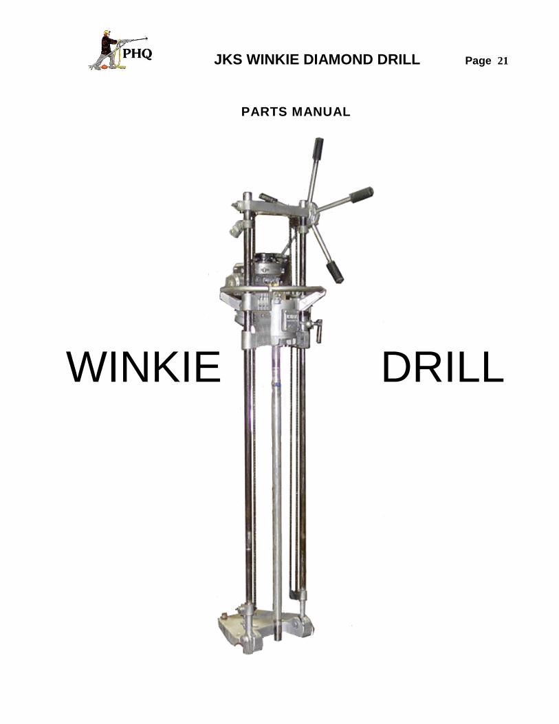
JKS WINKIE DIAMOND DRILL Page 21
PARTS MANUAL
WINKIE DRILL
JKS WINKIE DIAMOND DRILL Page 22
PARTS MANUAL
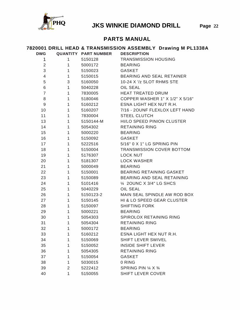
7820001 DRILL HEAD & TRANSMISSION ASSEMBLY Drawing M PL1338A DWG QUANTITY PART NUMBER DESCRIPTION
1 1 5150128 TRANSMISSION HOUSING
2 1 5000172 BEARING
3 1 5150023 GASKET
4 1 5150015 BEARING AND SEAL RETAINER
5 3 5160050 10-24 X '/z SLOT RHMS STE
6 1 5040228 OIL SEAL
7 1 7830005 HEAT TREATED DRUM
8 1 5180046 COPPER WASHER 1" X 1/2" X 5/16"
9 1 5160212 ESNA LIGHT HEX NUT R.H.
10 1 5160207 7/16 - 2OUNF FLEXLOX LEFT HAND
11 1 7830004 STEEL CLUTCH
13 1 5150144-M HI/LO SPEED PINION CLUSTER
14 1 5054302 RETAINING RING
15 1 5000220 BEARING
16 1 5150092 GASKET
17 1 5222516 5/16" 0 X 1" LG SPRING PIN
18 1 5150004 TRANSMISSION COVER BOTTOM
19 1 5176307 LOCK NUT
20 1 5181307 LOCK WASHER
21 1 5000049 BEARING
22 1 5150001 BEARING RETAINING GASKET
23 1 5150089 BEARING AND SEAL RETAINING
24 1 5101416 ¼ 2OUNC X 3/4" LG SHCS
25 1 5040229 OIL SEAL
26 1 5150123-2 MAIN SEAL SPINDLE AW ROD BOX
27 1 5150145 HI & LO SPEED GEAR CLUSTER
28 1 5150097 SHIFTING FORK
29 1 5000221 BEARING
30 1 5054303 SPIROLOX RETAINING RING
31 1 5054304 RETAINING RING
32 1 5000172 BEARING
33 1 5160212 ESNA LIGHT HEX NUT R.H.
34 1 5150069 SHIFT LEVER SWIVEL
35 1 5150052 INSIDE SHIFT LEVER
36 1 5054305 RETAINING RING
37 1 5150054 GASKET
38 1 5030015 0 RING
39 2 5222412 SPRING PIN ¼ X ¾
40 1 5150055 SHIFT LEVER COVER
JKS WINKIE DIAMOND DRILL Page 23
PARTS MANUAL
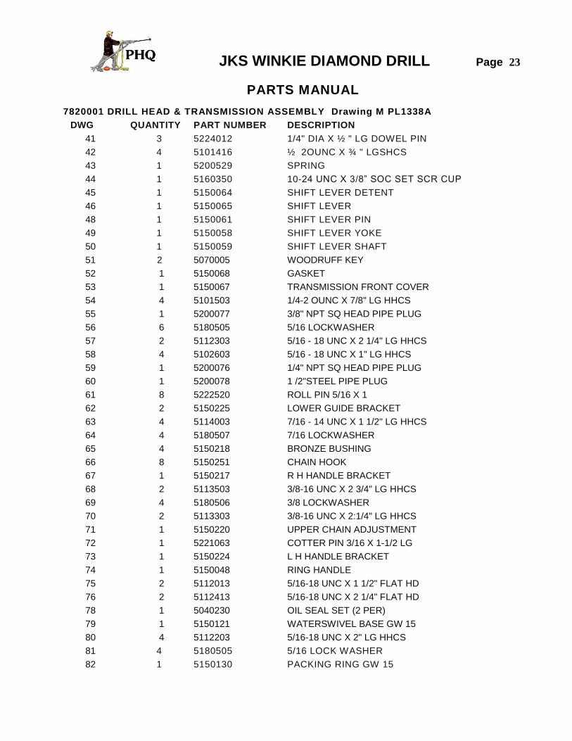
7820001 DRILL HEAD & TRANSMISSION ASSEMBLY Drawing M PL1338A
DWG QUANTITY PART NUMBER DESCRIPTION
41 3 5224012 1/4" DIA X ½ " LG DOWEL PIN
42 4 5101416 ½ 2OUNC X ¾ " LGSHCS
43 1 5200529 SPRING
44 1 5160350 10-24 UNC X 3/8” SOC SET SCR CUP
45 1 5150064 SHIFT LEVER DETENT
46 1 5150065 SHIFT LEVER
48 1 5150061 SHIFT LEVER PIN
49 1 5150058 SHIFT LEVER YOKE
50 1 5150059 SHIFT LEVER SHAFT
51 2 5070005 WOODRUFF KEY
52 1 5150068 GASKET
53 1 5150067 TRANSMISSION FRONT COVER
54 4 5101503 1/4-2 OUNC X 7/8" LG HHCS
55 1 5200077 3/8" NPT SQ HEAD PIPE PLUG
56 6 5180505 5/16 LOCKWASHER
57 2 5112303 5/16 - 18 UNC X 2 1/4" LG HHCS
58 4 5102603 5/16 - 18 UNC X 1" LG HHCS
59 1 5200076 1/4" NPT SQ HEAD PIPE PLUG
60 1 5200078 1 /2"STEEL PIPE PLUG
61 8 5222520 ROLL PIN 5/16 X 1
62 2 5150225 LOWER GUIDE BRACKET
63 4 5114003 7/16 - 14 UNC X 1 1/2" LG HHCS
64 4 5180507 7/16 LOCKWASHER
65 4 5150218 BRONZE BUSHING
66 8 5150251 CHAIN HOOK
67 1 5150217 R H HANDLE BRACKET
68 2 5113503 3/8-16 UNC X 2 3/4" LG HHCS
69 4 5180506 3/8 LOCKWASHER
70 2 5113303 3/8-16 UNC X 2:1/4" LG HHCS
71 1 5150220 UPPER CHAIN ADJUSTMENT
72 1 5221063 COTTER PIN 3/16 X 1-1/2 LG
73 1 5150224 L H HANDLE BRACKET
74 1 5150048 RING HANDLE
75 2 5112013 5/16-18 UNC X 1 1/2" FLAT HD
76 2 5112413 5/16-18 UNC X 2 1/4" FLAT HD
78 1 5040230 OIL SEAL SET (2 PER)
79 1 5150121 WATERSWIVEL BASE GW 15
80 4 5112203 5/16-18 UNC X 2" LG HHCS
81 4 5180505 5/16 LOCK WASHER
82 1 5150130 PACKING RING GW 15

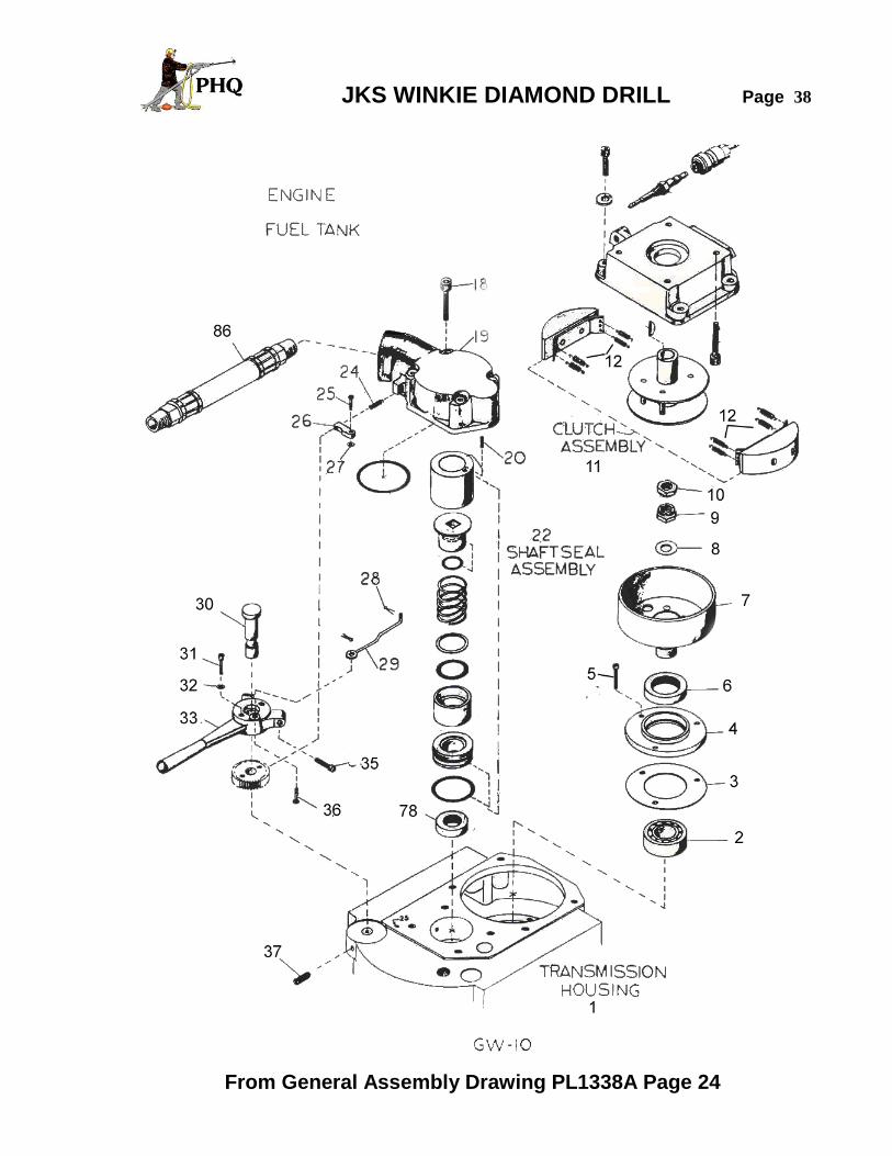
JKS WINKIE DIAMOND DRILL Page 24
PARTS MANUAL
7820001 DRILL HEAD & TRANSMISSION ASSEMBLY Drawing M PL1338A
DWG QUANTITY PART NUMBER DESCRIPTION
83 1 5150122 WATERSWIVEL GLAND GW15
84 2 5111203 ¼ 2OUNC X 2” LG HHCS
85 1 5180504 ¼ LOCK WASHER
86 1 5150049 10” HOSE ASSY
87 1 5203448 ½ “ DIAMETR BALL VALVE
88 1 8701082 SWIVEL ADAPTER ½ “ TO ¾ “
89 1 5070007 WOODRUFF KEY
Detail See GW10 Page 38 Detail Clutch See GW10-GW15 Page 38 Detail See GW15 Page 39 Detail Clutch See GW10-GW15 Page 39
Detail Transmission See Page 37 Detail Motor Transmission Mounts See Page 41
JKS WINKIE DIAMOND DRILL Page 25
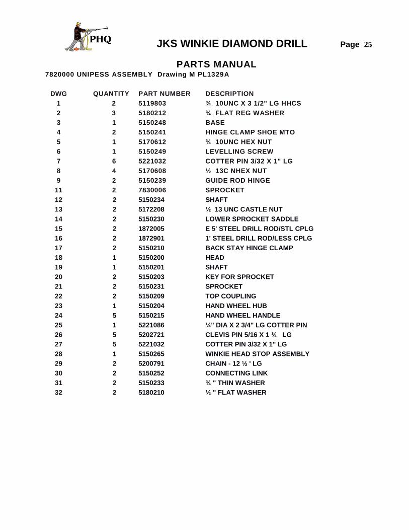
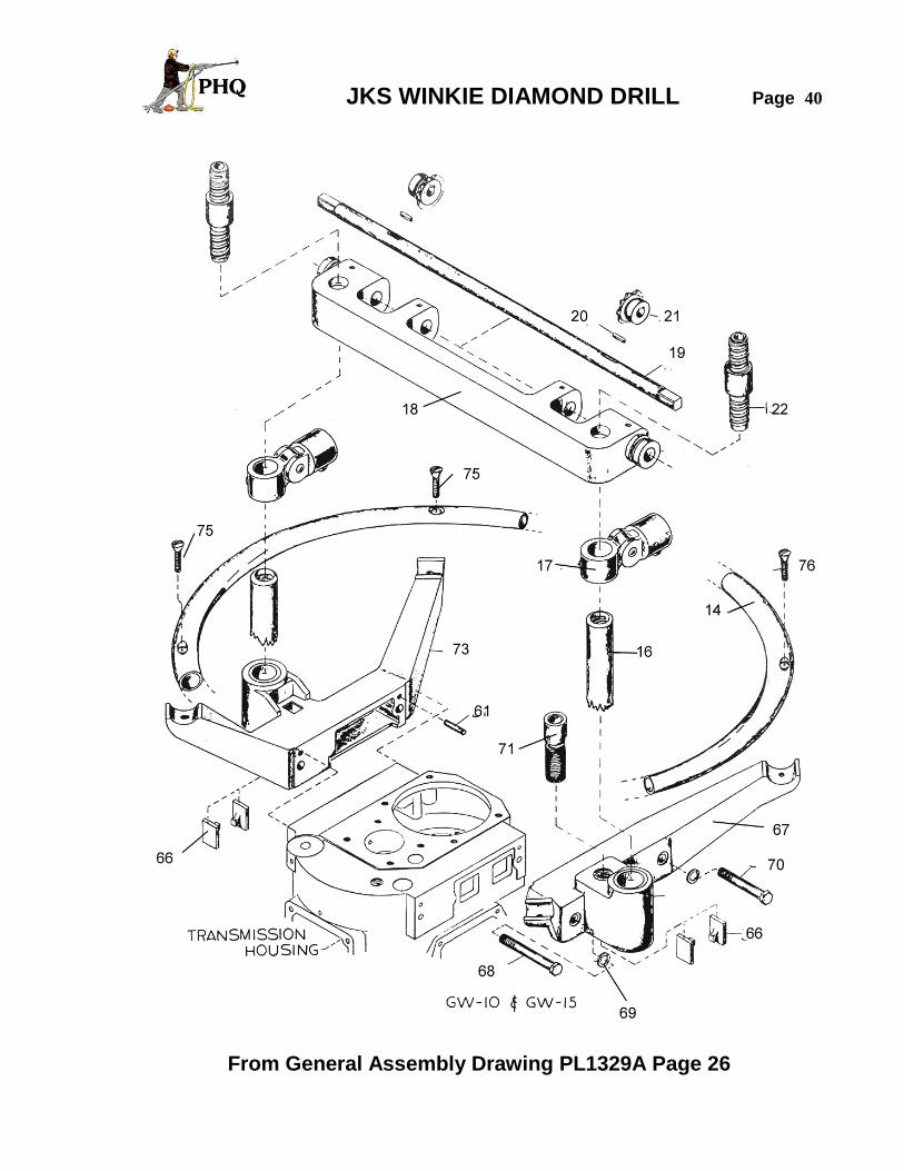
PARTS MANUAL 7820000 UNIPESS ASSEMBLY Drawing M PL1329A
DWG QUANTITY PART NUMBER DESCRIPTION
1 2 5119803 ¾ 10UNC X 3 1/2" LG HHCS
2 3 5180212 ¾ FLAT REG WASHER
3 1 5150248 BASE
4 2 5150241 HINGE CLAMP SHOE MTO
5 1 5170612 ¾ 10UNC HEX NUT
6 1 5150249 LEVELLING SCREW
7 6 5221032 COTTER PIN 3/32 X 1" LG
8 4 5170608 ½ 13C NHEX NUT
9 2 5150239 GUIDE ROD HINGE
11 2 7830006 SPROCKET
12 2 5150234 SHAFT
13 2 5172208 ½ 13 UNC CASTLE NUT
14 2 5150230 LOWER SPROCKET SADDLE
15 2 1872005 E 5' STEEL DRILL ROD/STL CPLG
16 2 1872901 1' STEEL DRILL ROD/LESS CPLG
17 2 5150210 BACK STAY HINGE CLAMP
18 1 5150200 HEAD
19 1 5150201 SHAFT
20 2 5150203 KEY FOR SPROCKET
21 2 5150231 SPROCKET
22 2 5150209 TOP COUPLING
23 1 5150204 HAND WHEEL HUB
24 5 5150215 HAND WHEEL HANDLE
25 1 5221086 ¼" DIA X 2 3/4" LG COTTER PIN
26 5 5202721 CLEVIS PIN 5/16 X 1 ¾ LG
27 5 5221032 COTTER PIN 3/32 X 1" LG
28 1 5150265 WINKIE HEAD STOP ASSEMBLY
29 2 5200791 CHAIN - 12 ½ ' LG
30 2 5150252 CONNECTING LINK
31 2 5150233 ¾ " THIN WASHER
32 2 5180210 ½ " FLAT WASHER
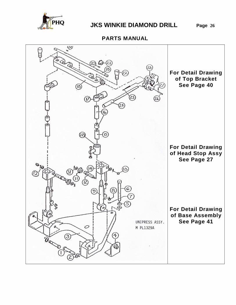
JKS WINKIE DIAMOND DRILL Page 26
PARTS MANUAL
For Detail Drawing of Top Bracket
See Page 40
For Detail Drawing of Head Stop Assy
See Page 27
For Detail Drawing of Base Assembly
See Page 41

JKS WINKIE DIAMOND DRILL Page 27
PARTS MANUAL
WK5150265 WINKIE HEAD STOP ASSEMBLY Drawing PL1527A
DWG QUANTITY PART NUMBER DESCRIPTION
1 1 5150265-4 BODY
2 1 5150265-1 HANDLE
3 1 5150265-3 ADJUSTING SCREW
4 1 5150265-2 SHOE
Item 8 in the General Assembly Drawing of Unipress Assembly Page 26

JKS WINKIE DIAMOND DRILL Page 28
PARTS MANUAL
7820002 ENGINE GROUP (CHRYSLER TWO STROKE)
DWG QUANTITY PART NUMBER DESCRIPTION
1 1 5230214 WINKLE ENGINE ASSY/10HP/ELECT. IGN.
2 1 175279 MUFFLER GASKET
3 1 5151598 WINKIE MUFFLER
4 1 5150127 MOTOR ADAP'T'ER GW 15
5 4 5102603 5/16 18UNC X 1" LG HHCS
6 8 5180505 5/16 LOCKWASHER
7 4 5102603 5/16 18UNC X 1" LG HHCS
8 12 6784549 CLEAR GAS LINE
9 1 5201490 3/8 TO 7/8 O.D. CLAMP
10 1 5310069 QUICK DISCONNECT MALE
13 1 5150028 GAS TANK ASSEMBLY
14 4 5170605 5/16 18UNC HEX NUT
15 1 5200530 SPRING
16 1 5160213 #10 24UNC X 1/2LG RD HD SCREW
17 1 5150044 RATCHET PAWL
18 3 5180203 3/16 REG FLAT WASHER
19 1 5221022 COTTER PIN
20 1 5153215 THROTTLE LEVER LINK
21 2 5160339 MACH. SCREW 10-24 UNC X 1"
22 4 5180403 3/16 LIGHT LOCK WASHER
23 1 5153815 THROTTLE HAND LEVER
24 1 5150037 THROTTLE RACHET
25 2 5160338 MACH. SCREW 10-24 UNC X 3/4"
26 1 5150042 THROTTLE LINK PIVOT
27 1 5102323 5/16NC X 5/8 SOCHD ST SCREW
28 1 5150041 BRASS WASHER
29 1 5150034 THROTTLE LEVER SHAFT
30 4 5112016 5/16-18UNC X 1 1/2" LG SHCS

JKS WINKIE DIAMOND DRILL Page 29
Starter Fan Housing
REF PART NO. QTY. DESCRIPITON REF PART NO. QTY. DESCRIPTION
1* 1096 4 ¼ 20 x ½ PN HD 16* 560456 1 STARTER COP
2* 264063 1 COMPLETE STARTER 17 1927 3 10-32x3/8 PN HD
3* N/A 3 DOG SPRING 18 559408 1 COIL COVER
4* N/A 1 SPRING & KEEPER 19 174648-1 1 CYLINDER COVER
5* N/A 1 PULLEY WITH BEARING 20 8026 2 17/64 X ½ X 1/8 WASHER
6* K15585 1 ROPE 21 560596 1 FAN HOUSING
7* A250132 1 T-HANDLE & INSERT 22 1096 2 ¼ 20 x ½ PN HD
8* N/A 3 DOG 23 1439 4 ¼ 20 x 5/8 SLT RD HD
9* N/A 1 DOG RETAINER K264063 1 STARTER KIT
10* N/A 1 SCREW
11* N/A 1 BRAKE SPRING
12* 15603-1 1 STARTER SCREEN
14 1353 1 7/16 20 FLYWHEEL NUT
* INDICATES ITEMS INCLUDED IN THE K264063 STARTER KIT
JKS WINKIE DIAMOND DRILL Page 30
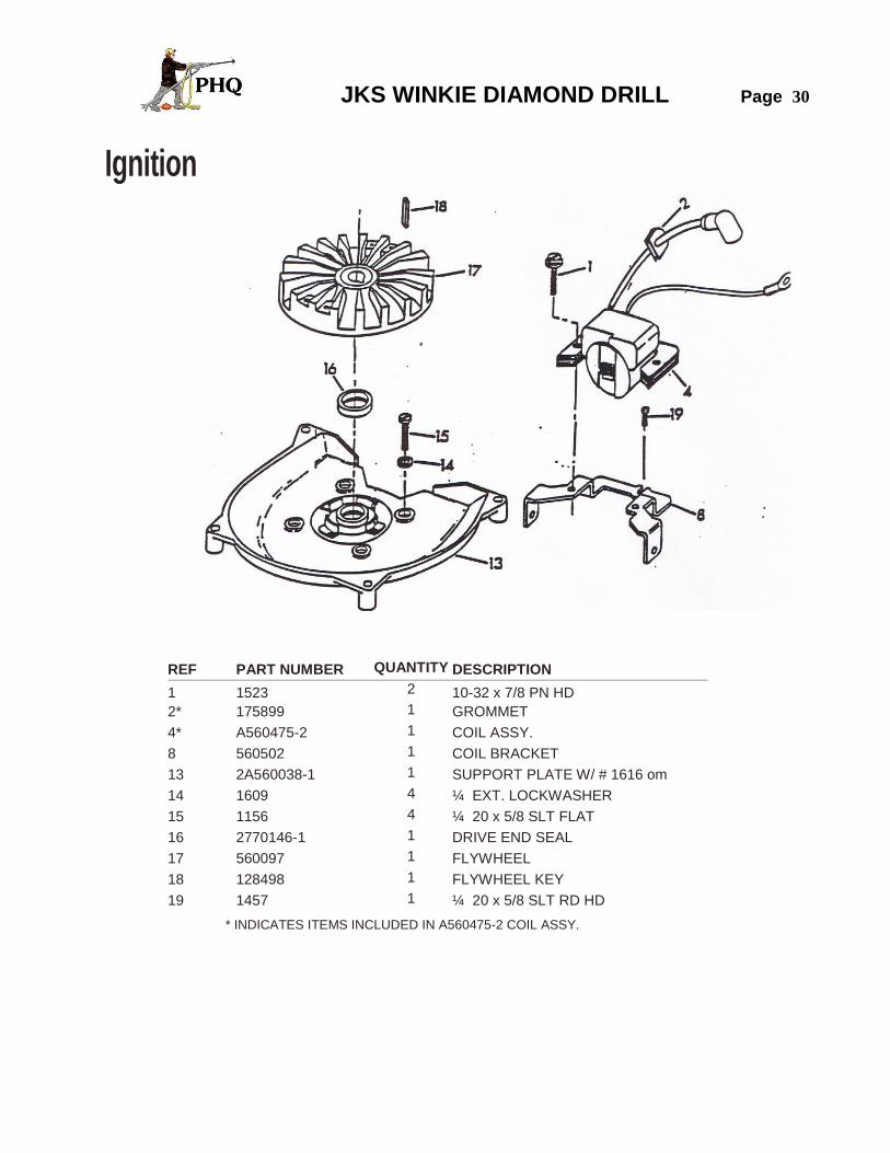
Ignition
REF PART NUMBER QUANTITY DESCRIPTION
1 1523 2 10-32 x 7/8 PN HD
2* 175899 1 GROMMET
4* A560475-2 1 COIL ASSY.
8 560502 1 COIL BRACKET
13 2A560038-1 1 SUPPORT PLATE W/ # 1616 om
14 1609 4 ¼ EXT. LOCKWASHER
15 1156 4 ¼ 20 x 5/8 SLT FLAT
16 2770146-1 1 DRIVE END SEAL
17 560097 1 FLYWHEEL
18 128498 1 FLYWHEEL KEY
19 1457 1 ¼ 20 x 5/8 SLT RD HD
* INDICATES ITEMS INCLUDED IN A560475-2 COIL ASSY.
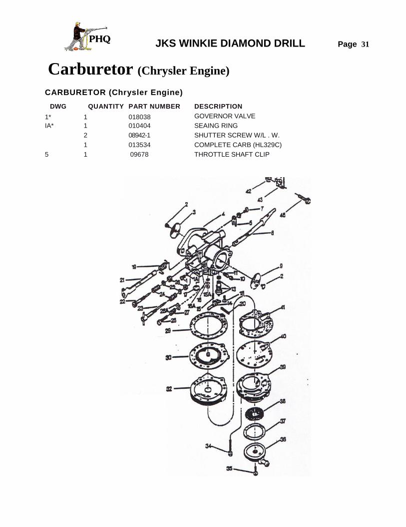
JKS WINKIE DIAMOND DRILL Page 31
Carburetor (Chrysler Engine)
CARBURETOR (Chrysler Engine)
DWG QUANTITY PART NUMBER DESCRIPTION
1* 1 018038 GOVERNOR VALVE
IA* 1 010404 SEAING RING
2 08942-1 SHUTTER SCREW W/L . W.
1 013534 COMPLETE CARB (HL329C)
5 1 09678 THROTTLE SHAFT CLIP
JKS WINKIE DIAMOND DRILL Page 32
Carburetor (Chrysler Engine)
CARBURETOR (Chrysler Engine)
DWG QUANTITY PART NUMBER DESCRIPTION
7 1 01974 RETAINING CLIP SCREW
8 1 014288 CHOKE SHAFT AND LEVER
9 1 013547 CHOKE SHUTTER
10 1 04784 CHOKE FRICTION BALL
11 1 08805 CHOKE FRICTION SPRING
13* 1 015206 INLET NEEDLE AND SEAT
14* 1 014020 INLET CONTROL LEVER
15 1 011503 INLET TENSION SPRING
16* 1 012345 RETAINING SPRING
16A* 1 012884 NOZZLE SCREEN
17* 1 02531 WELCH PLUG
18 1 013269 INLET CONTROL LEVER SCREW
18A* 1 012347 CHANNEL PLUG
19 1 013541 THROTTLE SHAFT RETURN SPRING
20 1 013406 INLET CONTROL LEVER PIN
21 1 013165 THROTTLE SHAFT AND LEVER
22 1 011498 IDLE ADJUSTING SCREW
23 1 012225 MAIN ADUSTING SCREW
24 2 08793 ADJUSTING SCREW SPRING
25* 2 011428 ADJUSTING SCREW WASHER
26* 2 011401 ADJUSTING SCREW PACKING
1 010404 GOVERNOR GASKET
27 1 0788 IDLE SPEED REGULATING SCREW SPRING
28 1 05095 IDLE SPEED REGULATING SCREW
29* 1 012473 DIAPHRAGM GASKET
30* 1 012475 DIAPHRAGM
32 1 013228 DIAPHRAGM COVER
34 6 018031 BODY SCREW
35 1 010571 STRAINER COVER GASKET
36 1 010527 STRAINER COVER
37* 1 010529 STARTER SCREEN
38* 1 010530 FUEL PUMP BODY
39 1 013335 FUEL DIAPHRAGM
40 1 012698 FUEL GASKET
41 1 012930 10-24 STOP NUT
42 1 7011 THROTTLE SHAFT
43 1 A2770589 ARM WITH #42 AND #45
45 1 1733 10 24 X 5/8 PN HD
* 1 10289 MESH SCREEN
1 K10232 CARURETOR REPAIR KIT COMPLETE
* INDICATES ITEMS INCLUDED IN K10232 CARBURETOR REPAIR KIT
JKS WINKIE DIAMOND DRILL Page 33
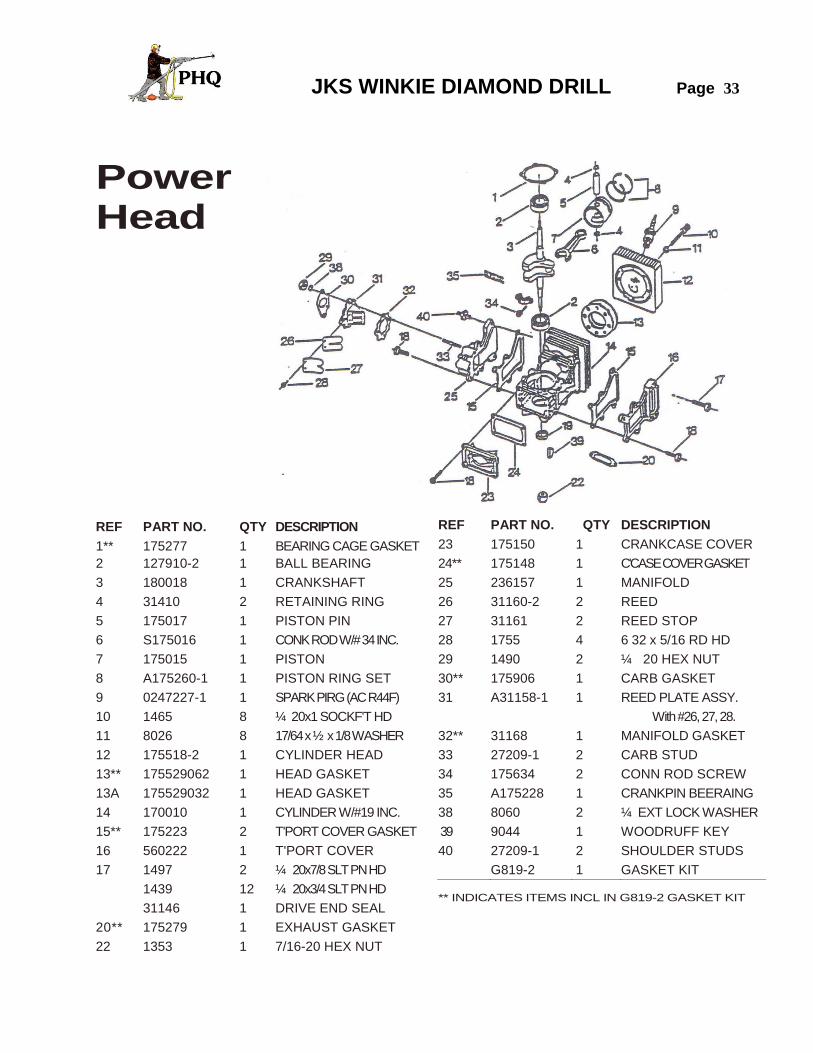
Power Head
REF PART NO. QTY DESCRIPTION
1** 175277 1 BEARING CAGE GASKET
2 127910-2 1 BALL BEARING
3 180018 1 CRANKSHAFT
4 31410 2 RETAINING RING
5 175017 1 PISTON PIN
6 S175016 1 CONK ROD W/# 34 INC.
7 175015 1 PISTON
8 A175260-1 1 PISTON RING SET
9 0247227-1 1 SPARK PIRG (AC R44F)
10 1465 8 ¼ 20x1 SOCKF'T HD
11 8026 8 17/64 x ½ x 1/8 WASHER
12 175518-2 1 CYLINDER HEAD
13** 175529062 1 HEAD GASKET
13A 175529032 1 HEAD GASKET
14 170010 1 CYLINDER W/#19 INC.
15** 175223 2 T'PORT COVER GASKET
16 560222 1 T'PORT COVER
17 1497 2 ¼ 20x7/8 SLT PN HD
1439 12 ¼ 20x3/4 SLT PN HD
31146 1 DRIVE END SEAL
20** 175279 1 EXHAUST GASKET
22 1353 1 7/16-20 HEX NUT
REF PART NO. QTY DESCRIPTION
23 175150 1 CRANKCASE COVER
24** 175148 1 C'CASE COVER GASKET
25 236157 1 MANIFOLD
26 31160-2 2 REED
27 31161 2 REED STOP
28 1755 4 6 32 x 5/16 RD HD
29 1490 2 ¼ 20 HEX NUT
30** 175906 1 CARB GASKET
31 A31158-1 1 REED PLATE ASSY.
With #26, 27, 28.
32** 31168 1 MANIFOLD GASKET
33 27209-1 2 CARB STUD
34 175634 2 CONN ROD SCREW
35 A175228 1 CRANKPIN BEERAING
38 8060 2 ¼ EXT LOCK WASHER
39 9044 1 WOODRUFF KEY
40 27209-1 2 SHOULDER STUDS
G819-2 1 GASKET KIT
** INDICATES ITEMS INCL IN G819-2 GASKET KIT
JKS WINKIE DIAMOND DRILL Page 34
OPERATING INSTRUCTIONS
FUEL MIXTURE
Normal operation mixture for Power Bee 2-cycle engines is 1/3 pint (BIA-TCW) two cycle oil with each gallon of gasoline thoroughly mixed in a separate clean container.
All brands of gasoline with octane rating of 87 are recommended. Avoid the use of gasoline-alcohol. Strain fuel mixture through a fine meshed screen when filling gasoline tank to remove dirt and water if present.
PREPARATION FOR STARTING
1. Fill gasoline tank with fuel mixture prepared as instructed above. Wipe up all spilled gasoline.
2. Open gasoline shut-off valve. 3. Move choke lever to closed position. NOTE: If engine is warm, it may not require choking. 4. Open the throttle and crank engine. 5. When engine starts, move choke lever to open position. NOTE: A starting point of 1 turn out from closed should be used for both the low and high speed mixture needles. Occasional readjustment may be required but it is not necessary to readjust for starting except for cold weather starting when it may be necessary to open the high speed adjusting needle an additional 1 /8 turn.
TO STOP ENGINE
Kill Button Switch will stop the engine by shorting magneto to ground.
CARBURETOR ADJUSTMENT
1. Turn both adjustment needles clockwise until completely closed.
CAUTION: Do not force needle tightly closed as the seat may be damaged.
2. Turn both needles counter-clockwise one turn.
3. Start engine and allow it to warm up, then, if carburetor setting is too "lean", engine will not run at full speed
and will "pop" and may stop. Turn main adjustment needle counter-clockwise an eighth of a turn at a time until the engine runs smoothly.
JKS WINKIE DIAMOND DRILL Page 35
If engine runs at full speed without load, but will not maintain full speed under load, turn the main adjustment needle counter-clockwise 1/8 turn.
If carburetor setting is too "rich", engine will not develop full power but will roll and run unevenly under load. Turn main adjustment needle clockwise 1/8 turn at a time until the engine runs smoothly.
4. To verify proper idle needle setting, start engine and allow to warm up. If motor surges, and runs at uneven speed, turn the idle adjustment needle slowly clockwise up to 1/4 turn. If this aggravates rather than corrects the situation, return to the original setting, then turn the idle adjustment needle slowly counter-clockwise up to 1/4 turn. This should cause the engine to "settle down" and run at a constant speed.
NOTE: If engine fails to accelerate, open idle screw 1/8 turn.
5. If engine runs too fast at idle speed, back out the idle stop screw a little at a time until desired speed is obtained. To increase idling speed, turn in the idle stop screw.
MAGNETO IGNITION
1. Breaker point gap should be set at .020". Set points with cam follower at highest point of breaker.
2. Directional arrow on cam must be UP.
3. For magneto inspection or service, contact your nearest authorized dealer.
4. If magneto stator plate is loosened or removed from the engine for any reason, be sure it is reinstalled as
follows:
A. Place stator plate in position.
B. Install hold down screws, but do not tighten.
C. Turn stator plate to the mid-range position.
D. Tighten screws.
E. Reset breaker points to .020" gap. This procedure places the stator plate in position for correct ignition timing.
AIR CLEANER Under ordinary operating conditions, the air cleaner should be cleaned daily. However, under extremely dirty condition, more frequent cleaning is recommended. To clean the air cleaner, follow equipment manufacturer's recommendations. IMPORTANT: Dirt that enters the engine through the carburetor is one of the greatest causes of engine wear. Therefore, it is very important that the air cleaner be serviced regularly.
JKS WINKIE DIAMOND DRILL Page 36
STARTER SCREEN The screen keeps dirt, etc., from entering the fan housing and clogging the air cooling passages.
Because this engine is air-cooled, it is necessary to keep this screen clean at all times to permit the unrestricted passage of air into the fan housing.
SPARK PLUG Check and clean spark plugs regularly. A fouled, dirty, or carboned spark plug causes hard starting and poor engine performance. Set spark plug gap at .030".
STORING MOTOR
The following steps should be taken to prepare your engine for storage.
1. Close gasoline shut-off valve.
2. Start engine and allow to run until it stops from lack of fuel. This will use up all the fuel in the carburetor
and prevent the formation of deposits due to evaporation of fuel.
3. Disconnect fuel line and permit all fuel to drain from the gasoline tank. Replace fuel line.
4. Remove spark plug and pour cup of motor oil into cylinder. Replace spark plug.
5. Crank engine two or three times to distribute oil throughout cylinder. This will coat the cylinder walls with oil and prevent rust from forming during the storage period.
TORQUE CHART FLYWHEEL 420 In. Lbs.
CONNECTING ROD 80-90 In. Lbs.
SPARK PLUG 120-180 In. Lbs. GENERAL SCREWS 10.24 30 In. Lbs. 1/4-20 70 In. Lbs.
10-32 35 In. Lbs. 5116-18 160 In. Lbs
114-28 75 In. Lbs.

JKS WINKIE DIAMOND DRILL Page 37
From General Assembly Drawing PL1338A Page 24
JKS WINKIE DIAMOND DRILL Page 38
From General Assembly Drawing PL1338A Page 24

JKS WINKIE DIAMOND DRILL Page 39
From General Assembly Drawing PL1338A Page 24
JKS WINKIE DIAMOND DRILL Page 40
From General Assembly Drawing PL1329A Page 26
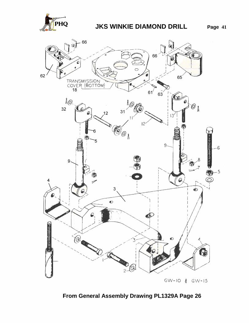
JKS WINKIE DIAMOND DRILL Page 41
From General Assembly Drawing PL1329A Page 26
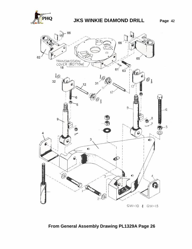
JKS WINKIE DIAMOND DRILL Page 42
From General Assembly Drawing PL1329A Page 26

JKS WINKIE DIAMOND DRILL Page 43
1. Install guide rod hinges (B) on base (A) with chain adjusting screws (C) to rear.
2. Mount drill with lower guide bushing (E) over
hinge thread (D). 3. Pass guide rods (G0 through upper guide
bushing (F0 and tighten onto the hinge threads (D).
4. Install backstay hinges (H). 5. Mount head and shaft assembly (I) on guide
rods (G) with shaft to rear. Tighten rod couplings (J) with long end down.
6. Pass chain over shaft through adjusting sleeve
(K) far enough to install chain hooks (see details). Pull hooks up into square recess against adj. sleeve (K). Pull up slack and hang chain on sprocket (L).
7. Pass other chain over shaft through square
hole (M) in guide arm, far enough to install chain hooks, pull back into square recess and take up slack to hand chain over sprocket (N).
8. Install handwheel (o) and raise drill off rod
hinges (B). Turn sleeve (k) up or down to equalize tension on both chains. Secure by passing cotter pin through hole in sleeve (K) and chain.
9. Pass free end of chains up through square
hole in lower guide bushing (E) far enough to install chain hooks and lower into square recess.
10. Remove lower sprocket pins (P) and mount
sprocket into chain. Replace pin (P) and tighten chain with adjusting nut (Q).
NOTE: Engine Not Shown.

JKS WINKIE DIAMOND DRILL Page 44
GENERAL INFORMATION
HOW TO ORDER A formal purchase order on company letterhead mailed or faxed is satisfactory. Email orders are satisfactory if full company details are provided. Telephone orders should be confirmed in writing through mail, fax or Email. The purchase order should contain: the full company name, address, phone and fax numbers (for quick reference or clarification) as well as details to contact the authorizing purchasing personnel. Please list on the purchase order: quantity, part number, item description, price, shipping address and preferred routing for shipments When ordering complete machines or major assemblies please furnish complete descriptions of the power unit required, sprocket ratios preferred, swivelhead type, chuck jaws sizes, and other relative information of standard optional equipment preferred. When ordering pumps please furnish complete description of the power unit required, the sprocket size preferred, the bore size, if a transmission, chain or belt drive is preferred and if gear reduction is required.
WHERE TO SEND THE ORDER Mail or fax orders to:
Email orders to: [email protected]

JKS WINKIE DIAMOND DRILL Page 45
TERMS AND CONDITIONS
TERMS NORTH AMERICA: Net 30 days on approved credit Overdue payment of invoices incur monthly interest charges of 1.5%) EXPORT SALES : Confirmed irrevocable letter of credit drawn on Canadian Bank Net 30 days credit terms available through Canadian EDC guarantees If purchasing company has an acceptable EDC credit rating Visa or MasterCard acceptable for payment with references Payment in advance of shipment by wire transfer to Canadian Bank
DELIVERY Most items are available from stock and you will receive a confirmed order acknowledgement specifying shipment date. Shipments will be routed by the most direct and economical means of transportation unless otherwise specified and your order should indicate if partial orders are acceptable.
RETURN OF GOODS Goods may be returned with the advance express written permission of Parts HeadQuarters Inc. Goods returned are subject to 25% restocking charges. Special equipment is not returnable. Only new drilling material is returnable. No credit will be issued for used drill material or tools. Parts HeadQuarters Inc. retains the right to inspect and reject any material returned for credit and to deny credit for any goods judged not to be suitable for resale.
GENERAL INFORMATION Prices and specifications listed are subject to change at any time without notice. Quotations for products are dated and valid for no more than 60 days from the date shown. All prices are F.O.B. Parts HeadQuarters Inc warehouse, Burlington, Ontario, Canada, L7L 5H9. Federal and Provincial taxes where applicable are extra and charged on PHQ invoices. The cost of exporting documents and insurance may be added and shown on PHQ invoices. Prepaid freight and handling charges may be added and shown on PHQ invoices

JKS WINKIE DIAMOND DRILL Page 46
PHQ began twenty eight years ago to supply pneumatic underground mining equipment, replacement parts and mining hardware.
PHQ grew into the manufacturing of complete percussion drills, drill feeds, drill centralizers, remote control panels, mufflers, drill jumbos, diamond drills, high pressure pumps, diamond drill bits, rods, corebarrels, and accessories. .
PHQ cooperates in active research to find improvements for pneumatic drill equipment. We have successfully developed a patented anti-vibration damping handle for pneumatic Jackleg drills working with CANMET LLC the University of Sherbrooke and a consortium of six major Mining Groups in Quebec Canada.
PHQ continually strives toward excellence PHQ has maintained an ISO rated quality system since1996. PHQ up-graded our in-house quality system in 2009 from ISO9001:2000 to ISO9001:2008 and have passed subsequent audits of the up graded system with no faults whatsoever every year since.
Annual quality audits are conducted by QMI SAI GLOBAL
PHQ adopted the picture of a miner running a pneumatic hand held Jackleg drill as the main symbol of our company. The Jackleg miner is an integral part of the Logo that we proudly display on all PHQ literature. It signifies our commitment to producing superior pneumatic drilling equipment for the mining industry.