section iii – parts lists - dake corp
TRANSCRIPT

Manual V-16, V-24, VH-24, V-40 & VH-40 1 – Section III
JOHNSON VERTICAL BAND SAWSINSTRUCTION MANUAL AND PARTS LIST
SECTION III – Parts Lists FOR MODELS V-40 VH-40
MODEL: ________________________________________ SERIAL NUMBER: ________________________________ DATE PURCHASED: ______________________________
DAKE Division of JSJ 724 Robbins Road Grand Haven, Michigan 49417 616.842.7110 Phone 800-937-3253 616.842.0859 Fax 800-846-3253 Web: www.dakecorp.com E-mail : [email protected] [email protected]

Manual V-16, V-24, VH-24, V-40 & VH-40 2 – Section III
SECTION II - ASSEMBLIES & PARTS LIST INDEX
Top Bracket & Blade Tension - Figure 1.1............................................ 3-4 Tracking Band Wheel Assembly - Figure 1.2 .................................... 3-5 Table / Cradle & Trunion Assembly, Hydraulic - Figure 2.1 / 2.2 ......... 6-7 Control Valve Assembly, Hydraulic - Figure 2.3 ................................. 6-7 Profile Saw Attachment, Hydraulic - Figure 2.4 .................................. 9 Hydraulic Reservoir Assembly - Figure 2.5 ......................................... 10 Hydraulic Reservoir Pumping Unit - Figure 2.6 .................................. 10-11 Table Assembly, Mechanical - Figure 2.7 .......................................... 11-12 Cradle & Trunion Assembly, Mechanical – Figure 2.8 ……………….. 12 Transmission Assembly - Figure 3.1 – Figure V-16 ............................ 13-18 Lower Wheel With Flange - Figure 3.7 ............................................... 19 Gear Shift Assembly - Figure 3.8 ....................................................... 20 Motor & Pulley Assembly - Figure 3.9 ................................................ 21 Speed Regulator Upper / Lower Assembly - Figure 4.1 / 4.2 ............ 22-23 Tachometer Assembly - Figure 4.3 / 4.4 ............................................ 23-24 Grinder Motor & Wheel Assembly - Figure 4.5 ................................... 24 Blade Guard & Brush - Figure 4.6 ...................................................... 25 Chip Blower & Regulator Assembly - Figure 4.7 ................................ 26 Blade Guides - Figure 4.8 ................................................................... 26-27 Control Panel ....................................................................................... 27-28 Electrical Box Layout .......................................................................... 29 Welder ................................................................................................ 30

Manual V-16, V-24, VH-24, V-40 & VH-40 3 – Section III

Manual V-16, V-24, VH-24, V-40 & VH-40 4 – Section III
ITEM PART NAME PART NO. V-40 VH-40 1 Handwheel 81529 1 1 2 Adjusting Wheel Collar 81530 1 1 3 Spindle 81532 1 1 4 Crown Spring 81534 6 6 5 Axial Bearing 81536 1 1 6 Spacer 81538 1 1 7 Lath Gib 81540 2 2 8 Carriage 81542 1 1 9 Carriage Lower Portion 81544 1 1
10 Rack 81547 1 1 11 Screw 4mm x 16mm 81548 2 2 12 Pin 81549 1 1 13 Set Screw 6mm x 10mm 8 pitch 80529 1 1 14 Flat Head Screw 4mm x 6mm 81551 2 2 15 Needle Bearing K20x24x17 81552 1 1 16 Screw 8mm x 20mm 80521 9 9 17 Guide Post 81556 1 1 18 Set Screw 10mm x 20mm 81560 1 1 19 Threaded Sleeve 81558 4 4 20 Plate 81561 1 1 21 Handle Bolt 81563 1 1 22 Roll Pin 81654 1 1 23 Star Handle 81565 1 1 24 Cap Screw 6mm x 12mm 80625 3 3 25 Set Screw 6mm x 10mm 8 pitch 80529 1 1 26 Gear 81566 1 1 27 Roll Pin 81568 1 1 28 Handle 80501 1 1 29 Hand Wheel 80500 1 1 30 Flange 81569 1 1 31 Hand Wheel Adjusting Bolt 81570 1 1 32 Tension Collar Set Screw 1 1 33 Tension Indicator Collar 1 1
34 Tension Indicator Pointer Rod
Assembly 81973
(Cover for hole
for old gauge is 81972)
1 1
35 Indicator Pointer Return Spring 716500 1 1
36 Indicator Plate 1 1
37 Mounting Bolts 716501 1 1
38 Pivot Bolt 81571 2 2
39 Pivot Bolt Nut 81572 1 1
40 Plate Spacers 91573 2 2
TOP BRACKET ASSEMBLY – FIGURE 1.1

Manual V-16, V-24, VH-24, V-40 & VH-40 5 – Section III
ITEM PART NAME
PART NO. V-40 VH-40
1 Screw 8mm x 10mm 80618 4 4
2 Jam nut 8mm 81575 2 2
3 Set Screw 8mm x 25mm 81505 2 2
4 Nylon Bandage (80540) 80650 2 2
5 Upper Band Wheel 81577 2 2
5 Upper Band Wheel 81578 - -
6 Cap Screw 8mm x 25 mm
81572
8 8 7 Flange 2 2 8 Special Pin 88mm x 16mm dia 2 2 9 Set Screw 8mm x 16mm 2 2
10 Adjuster Casting 81579 2 2 11 Shoulder Bolt 81581 2 2 12 Bearing 62042 80685 4 4 13 Snap Ring 81584 4 4 14 Spacer 20.7mm IDx25mm OD 18.5mm 81586 2 2 15 Flat Washer 5/16” x 1/16” Thick 43632 8 8 16 Shaft Nut 81588 2 2 17 Screw (Special) 81590 2 2 18 Nut (Special Knurled) 81592 2 2 19 Adjusting Hand Wheel 81595 2 2
TRACKING BAND WHEEL ASSEMBLY – FIGURE 1.2

Manual V-16, V-24, VH-24, V-40 & VH-40 6 – Section III

Manual V-16, V-24, VH-24, V-40 & VH-40 7 – Section III
ITEM PART NAME PART NO. V-40 VH-40 1 Table Insert (Left Rear) 81597 - 1 2 Table Insert (Right Rear) 81598 - 1 3 Table Insert 81792 - 2 4 Table Casting 81700 - 1 5 Cap Screw 4mm x 12 mm 81701 - 10
ITEM PART NAME PART NO. V-40 VH-40 1 Bracket 81702 - 1 2 Guide Rod 81703 - 2 3 Guide Casting 81704 - 1 4 Cap Screw 8mm x 25mm 81705 - 3 5 Cap Screw 6mm x 20mm 81706 - 2 6 Cap Screw 81707 - 1 7 Blade Guide Bracket Casting 81708 - 1 8 Table Cradle Lower Part 24/40 81709 - 1 9 Special Rotation Bolt 81710 - 1 10 Flat Washer 81711 - 1 11 Nut 81712 - 1 12 Roll Pin 4mm x 30mm 81713 - 2 *13 Set Screw 8mm x 10mm 81714 - 2 *14 Ball .186 dia. 81715 - 2 15 Screw (Special) 12mm x 25mm 81716 - 2 16 Handle 81717 - 2 17 Roll Pin 2.5mm x 30mm 81718 - 2 *18 Piston Guide 81719 - 1 19 Cap Screw 8mm x 20mm 80521 - 1 20 O-Ring 20.2 .3 80558 - 2 *21 Seal Ring 80623 - 2 *22 Piston Shaft 80617 - 1 23 Seal Washer 81720 - 8 24 Bored Screw 80580 - 4 25 Flexible Hydraulic Hose 81721 - 2 *26 Washer 82100000 81722 - 1 *27 Piston Seal 22mm x 35mm 80560 - 2 *28 Piston 81723 - 1 *29 Collar 81724 - 1 *30 Cap Screw 8mm x 70mm 81725 - 1 31 Cap Screw 10mm x 30mm 81726 - 4 32 Set Screw 5mm x 7mm 81727 - 4 33 Cone Pin 81758 - 4 *34 Cylinder 81729 - 1 *35 Cylinder Head 80682 - 1 36 Terminal 81730 - 1 37 Cap Screw 8mm x 30mm 81731 - 1 38 Cradle Upper Tilting Bracket 81732 - 1 39 Table Guide Shaft Rod 81733 - 2 * Complete Cylinder Assembly 714814 - 1
Cradle & Trunion Assembly, Hydraulic – Figure 2.2
Table Assembly, Hydraulic – Figure 2.1
Manual V-16, V-24, VH-24, V-40 & VH-40 8 – Section III
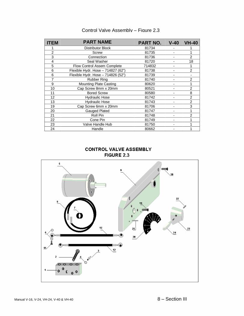
ITEM PART NAME PART NO. V-40 VH-40 1 Distributor Block 81734 - 1 2 Screw 81735 - 1 3 Connection 81736 - 2 4 Seal Washer 81720 - 18 5 Flow Control Assem Complete 714832 - 1 6 Flexible Hydr. Hose – 714827 (62”) 81738 - 2 6 Flexible Hydr. Hose – 714826 (52”) 81739 - - 7 Rubber Ring 81740 - 2 9 Mounting Plate Casting 80620 - 1
10 Cap Screw 8mm x 20mm 80521 - 2 11 Bored Screw 80580 - 8 12 Hydraulic Hose 81742 - 2 13 Hydraulic Hose 81743 - 2 19 Cap Screw 6mm x 20mm 81706 - 3 20 Gauged Plated 81747 - 1 21 Roll Pin 81748 - 2 22 Cone Pin 81749 - 1 23 Valve Handle Hub 81750 - 1 24 Handle 80662 - 1
Control Valve Assembly – Figure 2.3

Manual V-16, V-24, VH-24, V-40 & VH-40 9 – Section III
ITEM PART NAME PART NO. V-40 VH-40 1 Bevel Gear 81751 - 2 2 Roll Pin 4mm dia x 30mm 81713 - 2 3 Roll Pin 81752 - 5 4 Shaft 80664 - 1 5 Adjusting Collar 81753 - 1 6 Handwheel 80500 - 1 7 Handle 80501 - 1 8 Adjusting Ring 81754 - 2 9 Chain Sprocket 81755 - 1 10 Sprocket Shaft 81756 - 1 11 Roll Pin 81757 - 1 12 Bevel Gear 81758 - 1 13 Shaft 81759 - 1 14 Chain Link 80630 - 1 15 Chain 3940mm 81525 - 1 16 Handle 81760 - 2 17 Work Piece Holder w/ Handle 714863 - 1 18 Roller Shaft 81762 - 2 19 Roller Bracket 81763 - 2 20 Chain Pulley 81754 - 2 21 Snap Ring 81765 - 2 22 Set Screw 6mm x 10mm 8 pitch 80529 - 1 23 Trunion Locking Bolt 81526 - 2 24 Roll Pin 81718 - 3
Profile Sawing Attachment – Figure 2.4

Manual V-16, V-24, VH-24, V-40 & VH-40 10 – Section III
ITEM PART NAME PART NO. V-40 VH-40 1 Table Insert (Left Rear) 81597 1 - 2 Table Insert (Right Rear) 81598 1 - 3 Table Insert 81792 2 - 4 Table Casting 75678 1 - 5 Cap Screw 4mm x 12mm 81701 10 -
Table Assembly Mechanical – Figure 2.7

Manual V-16, V-24, VH-24, V-40 & VH-40 11 – Section III
ITEM PART NAME PART NO. V-40 VH-40
1 Guide Shaft Rod 81733 2 - 2 Miter Tilt Bracket 81732 1 - 3 Spindle Screw Shaft 81812 1 - 4 Table Miter Tilt Bracket Lower Portion 81709 1 - 4 Table Mount for V-16 85372 - - 5 Cap Screw 10mm x 30mm 81726 4 - 6 Locking Nut 81712 1 - 7 Washer 87711 1 - 8 Special Rotation Bolt 81710 1 - 9 Cap Screw 6mm x 20mm 81706 2 - 10 Lower Guider Holder Casting 81708 1 - 11 Cap Screw 4 - 12 Screw Nut support Plate 1 - 13 Screw Nut Support Plate Spacer Plate 1 - 14 Screw Nut 81811 1 - 15 Axial Bearing 81801 2 - 16 Control Bracket Casting 81813 1 - 17 Set Screw 6mm x 10mm 8 pitch 80529 1 -
18 & 19 Handwheel 12MM Bore 81802 1 - 19 Handwheel 10MM Bore (before 2006) 80500 1 -
Cradle & Trunion Assembly , Mechanical – 2.8

Manual V-16, V-24, VH-24, V-40 & VH-40 12 – Section III
Use Pinnacle 460 or equivalent oil
ITEM PART NAME PART NO. V-40 VH-40 1 Front Cover Plate 81819 1 1 2 Transmission Main Body Casting 81820 1 1 3 Cap Screw 8mm x 20mm 80521 8 8 4 Plug 81821 1 1 5 Set Screw 5mm x 7mm 81728 2 2 6 Alignment Roll Pin 81728 2 2 7 Hex Head Bolt 81822 4 4 8 Washer 81507 4 4 9 Threaded Adjustment Sleeve 81558 4 4
10 O-ring 1 x 1-3/16 x 3/32 81823 1 1 11 Oil Sight Glass 80571 1 1 Complete Transmission Assembly V-40/VH-40 714844 1 1
Transmission Assembly – Figure 3.1

Manual V-16, V-24, VH-24, V-40 & VH-40 13 – Section III
ITEM PART NAME PART NO. V-40 VH-40 1 Roll Pin 81824 2 2 2 Lever 81825 1 1 3 Cap Screw 6mm x 20mm 81706 6 6 4 Cover Plate 81826 1 1 5 Special Bolt (Shift Lever) 81827 1 1 6 Gear Shifter Casting 81828 1 1 7 Snap Ring 81829 1 1 8 Guide Collar 81830 1 1 9 Nut 81831 2 2 10 Screw 81832 1 1 11 Shaft 81833 1 1 12 Gear Shaft Fork 81834 1 1 13 Screw 81835 1 1
Transmission Assembly – Figure 3.2
Manual V-16, V-24, VH-24, V-40 & VH-40 14 – Section III
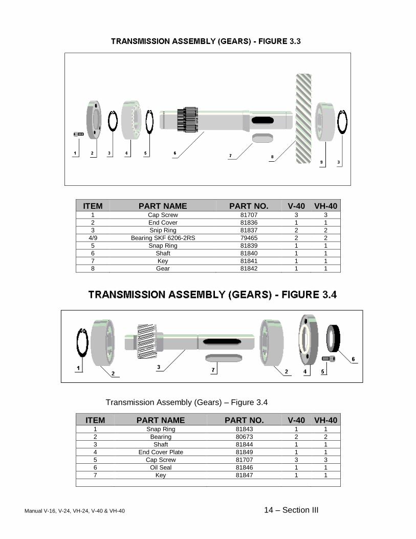
ITEM PART NAME PART NO. V-40 VH-40 1 Cap Screw 81707 3 3 2 End Cover 81836 1 1 3 Snip Ring 81837 2 2
4/9 Bearing SKF 6206-2RS 79465 2 2 5 Snap Ring 81839 1 1 6 Shaft 81840 1 1 7 Key 81841 1 1 8 Gear 81842 1 1
ITEM PART NAME PART NO. V-40 VH-40 1 Snap Ring 81843 1 1 2 Bearing 80673 2 2 3 Shaft 81844 1 1 4 End Cover Plate 81849 1 1 5 Cap Screw 81707 3 3 6 Oil Seal 81846 1 1 7 Key 81847 1 1
Transmission, Gear Assembly – Figure 3.3
Transmission Assembly (Gears) – Figure 3.4

Manual V-16, V-24, VH-24, V-40 & VH-40 15 – Section III
ITEM PART NAME PART NO. V-40 VH-40 1 Oil Ring 81848 1 1 2 Cap Screw 81707 3 3 3 End Cover Plate 81849 1 1 4 Snap Ring 81837 1 1 5 Bearing BCA 5206K 81850 1 1 6 Snap Ring 81839 1 1 7 Key 81851 1 1 8 Spline Shaft
**Models older than 1997 need to order the following in addition to the Spline Shaft
Shaft Thrust Bearing Needle Bearing
81852
81855 300296 81854
1
1 1 1
1
1 1 1
9 Gear 81853 1 1
Transmission Assembly (Gears) – Figure 3.5

Manual V-16, V-24, VH-24, V-40 & VH-40 16 – Section III
ITEM PART NAME PART NO. V-40 VH-40 1 Needle Bearing 81854 1 1 2 Shaft 81855 1 1 3 Key 81841 1 1 4 Bearing 81838 / 79465 1 1 5 Spacer Ring 81856 1 1 6 Gear 81857 1 1 7 Spacer Ring 81859 1 1 8 Snap Ring 81843 1 1 9 Bearing 80673 1 1
10 End Cover Plate 80643 1 1 11 Cap Screw 81707 3 3 12 Oil Seal 81846 1 1 13 Set Screw 81741 1 1 14 Snap Ring 81860 1 1 15 Tachometer Pulley 81861 1 1
ITEM PART NAME PART NO. V-40 VH-40 1 Band Wheel Cover – Sold as 714834x 80540 1 1 2 Band Wheel Casting 80618 1 1 3 Set Screw 81863 1 1 4 Flange 81865 1 1 5 Washer 5/16” x 1/16” thick 80522 4 4 6 Cap Screw 8mm x 25mm 81575 4 4 Complete Wheel Assembly 714834X 1 1
Lower Wheel with Flange – Figure 3.7
Transmission Assembly (Gears) – Figure 3.6

Manual V-16, V-24, VH-24, V-40 & VH-40 17 – Section III
ITEM PART NAME PART NO. V-40 VH-40 1 Lever Casting 81825 1 1 2 Roll Pin 81824 3 3 3 Lever Casting 80530 1 1 4 Jam Nut 81866 4 4 5 Ball Joint 81867 2 2 6 Washer 81507 2 2 7 Shaft 81870 1 1 8 Shaft 81873 1 1 9 Screw 81741 1 1 10 Snap Ring 81874 1 1 11 Washer 81875 1 1 12 Spring 81876 1 1 13 Collar 81877 1 1 14 Handle 81878 1 1 15 Special Bolt 81879 1 1
Gear Shift Assembly – Figure 3.8

Manual V-16, V-24, VH-24, V-40 & VH-40 18 – Section III
ITEM PART NAME PART NO. V-40 VH-40 1 Variator (Pulley) Transmission Side 80538 1 1 2 Drive Belt Cogged 37 x 10 x 1500mm 80535 - - 2 Drive Belt Cogged 37 x 10 x 1320mm 80532 1 1 3 Variator (Pulley) Motor Side 80537 1 1 4 Drive Motor 220/440 V. 60 Hz. 80531 1 1 5 Motor Base 81880 2 2 6 Threaded Adjusting Sleeve 81558 4 4 7 Washer 81507 4 4 8 Cap Screw 81822 4 4 9 Cap Screw 80631 4 4 10 Washer 81890 8 8 11 Nut 81889 4 4 12 Bolt 80660 1 1 13 Washer 80661 1 1 14 Key 81841 1 1 15 Snap Ring 1 1 Variator Spring for transmission 80562 1 1 Variator Bearing for motor side 77027 1 1 Bolt 81881 1 1 Washer 70270 1 1
Motor and Pulley Assembly – Figure 3.9

Manual V-16, V-24, VH-24, V-40 & VH-40 19 – Section III
ITEM PART NAME PART NO. V-40 VH-40 1 Connection Fitting 81891 1 1 2 Seal Washer 80576 1 1 3 Plug 81893 1 1 4 Seal Washer 80576 1 1 5 Cylinder Body 81894 1 1 6 Cap Screw 80625 3 3 7 O-ring 19.3x2.4mm 80563 2 2 8 Piston 81895 1 1 9 Piston Nut 81896 1 1 10 Hand Wheel and Handle 80500/80501 1 1 11 Set Screw 6mm x 10mm 8 pitch 80529 1 1 12 Jam Nuts 2 2 Complete Assembly 714813 1 1
Speed Regulator, Upper Assembly – Figure 4.1

Manual V-16, V-24, VH-24, V-40 & VH-40 20 – Section III
ITEM PART NAME PART NO. V-40 VH-40 1 Snap Ring 81829 1 1 2 Bolt 81897 1 1 3 Lever Casting 80666 1 1 4 Special Pivot Bolt 80667 1 1 5 Bracket 80665 1 1 6 Washer 81507 2 2 7 Cap Screw 81898 2 2 8 Cap Screw 81899 1 1 9 Nut 81900 1 1
10 Bracket 81901 1 1 11 Cap Screw 81902 2 2 12 Washer 81507 2 2 13 Piston 81903 1 1 14 O-Ring 3x2x4mm 80564 2 2 15 Cylinder 81904 1 1 16 Ball 81905 1 1 17 Screw 80592 1 1 18 Connection Fitting 81891 1 1 19 Copper Tubing 1 1 Complete Assembly 714836 1 1
Speed Regulator, Lower Assembly – Figure 4.2

Manual V-16, V-24, VH-24, V-40 & VH-40 21 – Section III
ITEM PART NAME PART NO. V-40 VH-40
1 Digital Display Unit (not available for the E-16 110v) 301832 1 1 2 Prox. Sensor with Cord 301833 1 1 3 Magnet for wheel 300226 1 1
Digital Tachometer Assembly – Figure 4.3 / 4.4
Digital Tachometer Assembly – Figure 4.3 / 4.4

Manual V-16, V-24, VH-24, V-40 & VH-40 22 – Section III
ITEM PART NAME PART NO. V-40 VH-40 1 Motor 220/440 Volt 60 Hz. 80503 1 1 2 Cap Screw 81923 4 4 3 Adaptor Flange 80590 1 1 4 Grinding Wheel 80512 1 1 5 Washer 80518 1 1 6 Mounting Screw 80519 1 1 7 Wheel Cover Bracket 80515 1 1 8 Cap Screw 80516 3 3 9 Wheel Guard 80513 1 1 10 Wheel Guard Thumb Screw 80514 1 1
Motor and Grinding Wheel Assembly – Figure 4.5

Manual V-16, V-24, VH-24, V-40 & VH-40 23 – Section III
ITEM PART NAME PART NO. V-40 VH-40 1 Screw 81924 2 2 2 Grinder Cover Guard 81925 1 1 3 Brush Mounting Bolt 81926 1 1 4 Wood Screw 81924 2 2 5 Knurled Thumb Screws 81526 - - 6 Washer 80527 - - 7 Blade Guard 81934 1 1 8 Cap Screw 80265 2 2 9 Mounting Screw 81926 2 2
10 Chip Wheel Guard 81929 1 1 11 Brush Holder 81930 1 1 12 Wire Chip Brush 81931 1 1 13 Upper Blade Cover 81932 - - 14 Alignment Screws 81933 2 2 15 Blade Guard 80527 1 1 16 Cap Screw 80625 2 2 17 Lower Blade Cover w/ Plexiglas 78205 1 1 17 Lower Blade Cover w/ Plexiglas 78206 - - Blade Guard V-24 80653 - - Cover 84839 1 1
Blade Guard & Brush – Figure 4.6

Manual V-16, V-24, VH-24, V-40 & VH-40 24 – Section III
ITEM PART NAME PART NO. V-40 VH-40 Chip Blower Kit 300668 1 1 Hose Barb 35087 2 2 2 Reducer Fitting 2 2 3 Pre-Set Air Regulator 77269 1 1 4 Lock Line Pivot Fitting 77328 1 1 5 Flex Line Nozzle Assembly 77327/77326 1 1 6 Reducer Fitting 1 1 7 Plastic Air Hose 1 1 8 Coupling Fitting 1 1
Chip Blower & Regulator – Figure 4.7
Manual V-16, V-24, VH-24, V-40 & VH-40 25 – Section III
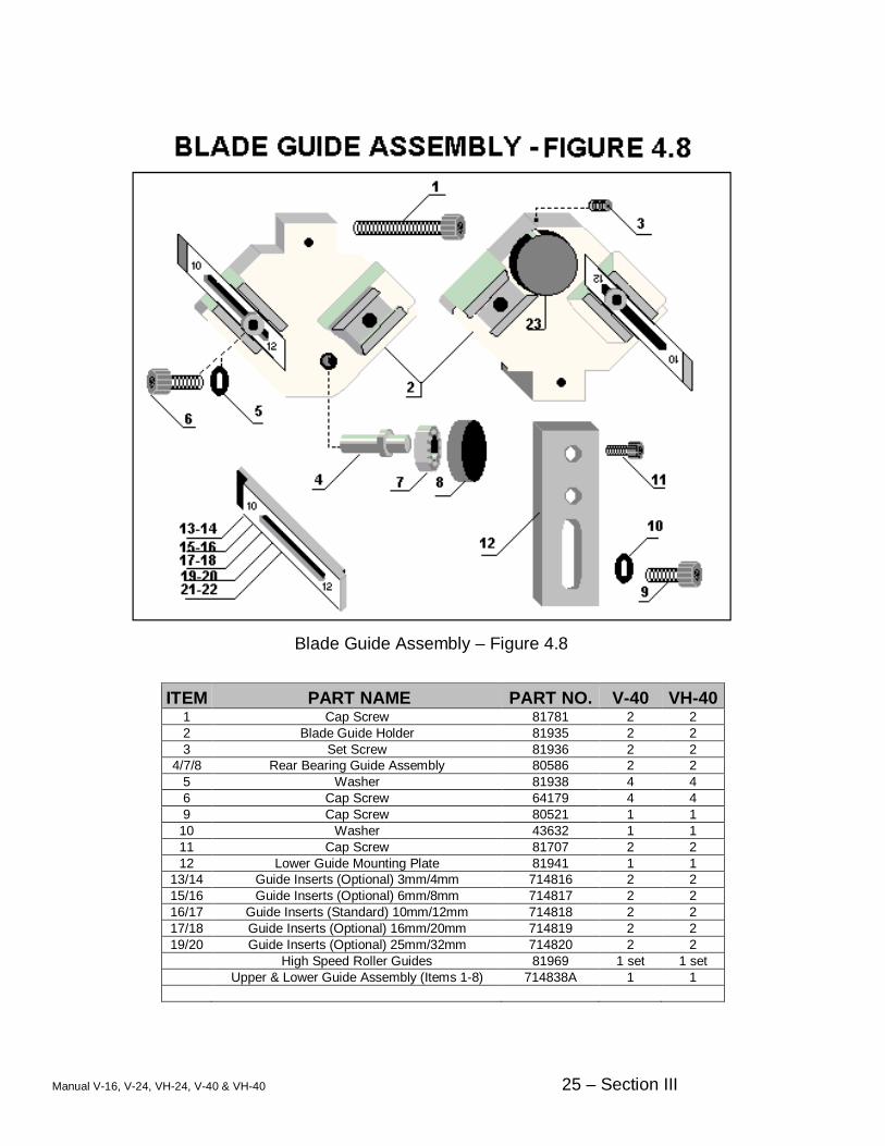
ITEM PART NAME PART NO. V-40 VH-40 1 Cap Screw 81781 2 2 2 Blade Guide Holder 81935 2 2 3 Set Screw 81936 2 2
4/7/8 Rear Bearing Guide Assembly 80586 2 2 5 Washer 81938 4 4 6 Cap Screw 64179 4 4 9 Cap Screw 80521 1 1
10 Washer 43632 1 1 11 Cap Screw 81707 2 2 12 Lower Guide Mounting Plate 81941 1 1
13/14 Guide Inserts (Optional) 3mm/4mm 714816 2 2 15/16 Guide Inserts (Optional) 6mm/8mm 714817 2 2 16/17 Guide Inserts (Standard) 10mm/12mm 714818 2 2 17/18 Guide Inserts (Optional) 16mm/20mm 714819 2 2 19/20 Guide Inserts (Optional) 25mm/32mm 714820 2 2
High Speed Roller Guides 81969 1 set 1 set Upper & Lower Guide Assembly (Items 1-8) 714838A 1 1
Blade Guide Assembly – Figure 4.8

Manual V-16, V-24, VH-24, V-40 & VH-40 26 – Section III
ITEM PART NAME PART NO. V-40 VH-40 1 Lighted Push Button (green) 716540 2 3 2 Stop Push Button 716539 2 3 3 Emergency Push Button 716538 1 1 4 Face Plate 80679 1 1 5 Lighted Push Button (yellow) 716541 1 1
ITEM PART NAME (NOT SHOWN) PART NO. V-40 VH-40 Door Microswitch 80553 5 5 Door Latch 300628
Door Key – (Old style square bottom) Door Key – (New style metal)
81968 80511 1 1
Main Cam Switch 1-7/8” square – Smaller 80554 1 1 Main Cam Switch 2-5/8” square – Larger 80554L 1 1
Control Panel

Manual V-16, V-24, VH-24, V-40 & VH-40 27 – Section III
ITEM PART NAME (NOT SHOWN) PART NO. V-40 VH-40 Transformer 302910 1 1
K1,K2,K3 Contactor 301794 3 4 Blade Drive Relay Overload for K1, 3.2-16 Amp 301795 1 1
Grinder Relay Overload for K2, .2 – 1 Amp 301797 1 1 Hydraulic Relay Overload K3, 1 – 5 Amp 301796 - 1
ELECTRICAL PANEL LAYOUT V-40, VH-40 Models

Manual V-16, V-24, VH-24, V-40 & VH-40 28 – Section III
ITEM PART NAME PART NO. V-40 VH-40 Welding Device 220 Volt 300516 1 1
Transformer S-25 77400 1 1 2 Weld Current Switch 80621 1 1 3 Anneal Switch 81964 1 1 4
Shear Blade Assembly - Top width 18 mm Replacement Blades – Top width 18 mm
Shear Blade Assembly – Top width 15 mm Replacement Blades – Top width 15 mm
80508 77274
714815 300655
1 1
1 1
1 1
1 1
5 Microswitch ISK TYPM6 72451 2 2 6 Lever Jaw Clamp 76056 2 2 Knurled Screw Blade Rest – Not Illustrated 78684 1 1 Black Knob Only for item 2, 3 and two underneath 77531 4 4