operating instructions series model 7500 - teledyne
TRANSCRIPT

TELEDYNE ANALYTICAL INSTRUMENTS
OPERATING INSTRUCTIONS
Series Model 7500 Infrared Gas Analyzer
DANGER
HIGHLY TOXIC AND OR FLAMMABLE LIQUIDS OR GASES MAY BE PRESENT IN THIS
MONITORING SYSTEM.
PERSONAL PROTECTIVE EQUIPMENT MAY BE REQUIRED WHEN SERVICING THIS SYSTEM.
HAZARDOUS VOLTAGES EXIST ON CERTAIN COMPONENTS INTERNALLY WHICH MAY PERSIST
FOR A TIME EVEN AFTER THE POWER IS TURNED OFF AND DISCONNECTED.
ONLY AUTHORIZED PERSONNEL SHOULD CONDUCT MAINTENANCE AND/OR SERVICING.
BEFORE CONDUCTING ANY MAINTENANCE OR SERVICING CONSULT WITH AUTHORIZED
SUPERVISOR/MANAGER.
P/N 07/07/11

2 Model 7500 Instruction Manual
Teledyne Analytical Instruments
PREFACE
We are grateful for your purchase of Teledyne Analytical Instrumentʼs Model 7500 Infrared Gas Analyzer.
• First read this instruction manual carefully until an adequate understanding is acquired, and then proceed to installation, operation and maintenance of the analyzer. Wrong handling may cause an accident or injury.
• The specifications of this analyzer are subject to change without prior notice for further product improvement.
• Modification of this analyzer is strictly prohibited unless a written approval is obtained from the manufacturer. Teledyne will not bear any responsibility for a trouble caused by such a modification.
• This instruction manual shall be stored by the person who actually uses the analyzer.
• After reading the manual, be sure to store it at a place easier to access.
• This instruction manual should be delivered to the end user without fail
Delivered Items:
Analyzer main frame (1) Power cable (1) Fuse (2) Rating : 1 A Instruction manual (1) Side rail (2) Option
• It is prohibited to transfer part or all of this manual without Teledyneʼs permission.
• Description in this manual is subject to change without prior notice for further improvement.

3 Model 7500 Instruction Manual
Teledyne Analytical Instruments
SAFETY PRECAUTIONSPlease read this section carefully to ensure using the analyzer in the correct way.
The cautionary descriptions listed here contain important information about safety, so they should always be observed. Those safety precautions are ranked in 3 levels, “DANGER”, “CAUTION” and “PROHIBITED”.
DANGER Wrong handling may cause a dangerous situation, in which there is a risk of death or heavy injury.
CAUTION Wrong handling may invite a dangerous situation, in which there is a possibility of medium-level trouble or slight injury or only physical damage is predictable.
PROHIBITED Items which must not be done are noted.
Caution on installation and transport of gas analyzerDANGER • This unit is not explosion-proof type. Do not
use it in a place with explosive gases to prevent explosion, fire or other serious accidents.
CAUTION • For installation, observe the rule on it given in the instruction manual and select a place where the weight of gas analyzer can be endured. Installation at an unsuited place may cause turnover or fall and there is a risk of injury.• For lifting the gas analyzer, be sure to wear protective gloves. Bare hands may invite an injury.• Before transport, fix the casing so that it will not open. Otherwise, the casing may be separated and fall to cause an injury.• During installation work, care should be taken to keep the unit free from cable chips or other foreign objects. Otherwise, it may cause fire, trouble or malfunction of the unit.

4 Model 7500 Instruction Manual
Teledyne Analytical Instruments
Caution on pipingDANGER In piping, the following precautions should be
observed. Wrong piping may cause gas leakage. If the leaking gas contains a toxic component, there is a risk of serious accident being induced. Also, if combustible gas is contained, there is a danger of explosion, fire or the like occurring.• Connect pipes correctly referring to the instruction manual.• Exhaust should be led outdoors so that it will not remain in the locker and installation room.• Exhaust from the analyzer should be relieved in the atmospheric air in order that an unnecessary pressure will not be applied to the analyzer. Otherwise, any pipe in the analyzer may be disconnected to cause gas leakage.• For piping, use a pipe and a pressure reducing valve to which oil and grease are not adhering. If such a material is adhering, a fire or the like accident may be caused.
Caution on wiringCAUTION • Wiring work must be performed with the main
power set to OFF to prevent electric shocks.• Enforce construction of class-D rounding wire by all means. If the specified grounding construction is neglected, a shock hazard or fault may be caused.• Wires should be the proper one meeting the ratings of this instrument. If using a wire which cannot endure the ratings, a fire may occur.• Be sure to use a power supply of correct rating. Connection of power supply of incorrect rating may cause fire.
Caution on useDANGER • For correct handling of calibration gas or other
reference gases, carefully read their instruction manuals beforehand. Otherwise, carbon monoxide or other hazardous gases may cause an intoxication particularly.
CAUTION • Before leaving unused for a long time or restarting after left at such a status for an extended length of time, follow the directions of each instruction manual because they are different from normal starting or shutdown. Otherwise, the performance may be poor and accidents or injuries may be caused.• Do not operate the analyzer for a long time with its door left open. Otherwise, dust, foreign matter, etc. may stick on internal walls, thereby causing faults.

5 Model 7500 Instruction Manual
Teledyne Analytical Instruments
Caution on usePROHIBITED • Do not allow metal, finger or others to touch the
input/output terminals in the instrument. Otherwise, shock hazard or injury may occur.• Do not smoke nor use a flame near the gas analyzer. Otherwise, a fire may be caused.• Do not allow water to go into the gas analyzer. Otherwise, hazard shock or fire in the instrument may be caused.
Caution on maintenance and checkDANGER • When doors are open during maintenance or
inspection, be sure to purge sufficiently the inside of the gas analyzer as well as the measuring gas line with nitrogen or air, in order to prevent poisoning, fire or explosion due to gas leak.
CAUTION Be sure to observe the following for safe operation avoiding the shock hazard and injury.• Remove the watch and other metallic objects before work.• Do not touch the instrument wet-handed.• If the fuse is blown, eliminate the cause, and then replace it with the one of the same capacity and type as before. Otherwise, shock hazard or fault may be caused.• Do not use a replacement part other than specified by the instrument maker. Otherwise, adequate performance will not be provided. Besides, an accident or fault may be caused.• Replacement parts such as a maintenance part should be disposed of as incombustibles. For details, follow the local ordinance.
OthersCAUTION • If the cause of any fault cannot be determined
despite reference to the instruction manual, be sure to contact the factory. If the instrument is disassembled carelessly, you may have a shock hazard or injury.

6 Model 7500 Instruction Manual
Teledyne Analytical Instruments
CONTENTS
PREFACE .............................................................................................................................2CAUTION ON SAFETY ..........................................................................................................31. OVERVIEW.........................................................................................................................82. NAME AND DESCRIPTION OF EACH PART ...................................................................9 2.1 Description of each unit ......................................................................................93. INSTALLATION ................................................................................................................10 3.1 Installation conditions ........................................................................................10 3.2 Installation of analyzer .......................................................................................11 3.3 Piping .................................................................................................................11 3.4 Sampling ............................................................................................................12 3.5 Wiring method ....................................................................................................154. OPERATION ................................................................................................... ..................24 4.1 Preparation for operation ....................................................................................24 4.2 Warm-up operation and regular operation ..........................................................245. DESCRIPTION OF DISPLAY AND OPERATION PANEL .................................................25 5.1 Name and description of operation panel ...........................................................25 5.2 Overview of display and operation panel ............................................................26 5.3 Overview of display screen .................................................................................27 5.4 General operation................................................................................................306. SETTING AND CALIBRATION...........................................................................................31 6.1 Changeover of range ..........................................................................................31 6.2 Calibration setting ...............................................................................................32 6.2.1 Setting of calibration concentration......................................................32 6.2.2 Setting of manual zero calibration ...................................................... 34 6.2.3 Setting of calibration range ..................................................................36 6.2.4 Setting of auto-calibration component .................................................38 6.3 Alarm setting ........................................................................................................40 6.3.1 Setting of alarm values ........................................................................40 6.3.2 Hysteresis setting ................................................................................42 6.4 Setting of auto calibration ....................................................................................43 6.4.1 Auto calibration ....................................................................................43 6.4.2 Forced stop of auto calibration ............................................................45 6.5 Setting of auto zero calibration ............................................................................47 6.5.1 Auto zero calibration ............................................................................47 6.5.2 Forced stop of auto zero calibration ....................................................49 6.6 Peak alarm setting ...............................................................................................51 6.7 Parameter setting ................................................................................................53

Teledyne Analytical Instruments
7 Model 7500 Instruction Manual
6.8 Maintenance mode …………………………………………………………………… 57
6.9 Calibration …………………………………………………………………………….. 59
6.9.1 Zero calibration …………………………………………………………… 59
6.9.2 Span calibration ………………………………………………………….. 60
7. MAINTENANCE ................................................................................................... 61
7.1 Daily check ............................................................................................ 61
7.2 Daily check and maintenance procedures ............................................ 61
7.3 Cleaning of measuring cell .................................................................... 62
7.3.1 Disassembly and assembly of measuring cell ....................... 62
7.3.2 How to clean cell ……………………………………………….. 67
8. TROUBLESHOOTING ......................................................................................... 68
8.1 Error message .......................................................................................... 68
9. SPECIFICATIONS ............................................................................................... 70
9.1 Specifications ………………………………………………………………. 70
9.2 Code symbols ………………………………………………………………. 73
9.3 Outline diagram …………………………………………………………….. 78
APPENDIX ………………………………………………………………………………… 80
Drawing List ............................................................................................................. 80

8 Model 7500 Instruction Manual
Teledyne Analytical Instruments
1. OVERVIEWThe Model 7500 infrared gas analyzer measures the concentrations of CO2, CO, CH4, SO2 and O2 contained in sample gas. CO2, CO, CH4 and SO2 are measured by non-dispersion infrared method, while O2 is measured by paramagnetic method. A maximum of 4 components including O2 (a maximum of 3 components for other than O2 measurement) are simultaneously measurable.
A high-sensitivity mass flow sensor is used in the detector unit of infrared method. Due to use of single beam system for measurement, maintenance is easy and an excellent stability is ensured for a long period of time.
In addition, a microprocessor is built in and a large sized liquid crystal display is provided for easier operation, higher accuracy and more functions.
This analyzer is thus optimum for combustion control of various industrial furnaces, botanical study and global atmospheric research.

9 Model 7500 Instruction Manual
Teledyne Analytical Instruments
2. NAME AND DESCRIPTION OF EACH PART 2.1 Description of each unit
Name Description1. Handle Draws the analyzer unit from the case.2. Power switch Turns ON/OFF this analyzer.3. Switch for back light Turn ON/OFF the back light of display.4. Display / Operation panel Liquid crystal display and keys for various
operational settings are arranged.5. Sampling gas inlet Port for connecting the sample gas injection pipe.6. Sampling gas outlet Port for connecting the pipe for discharging the
gas after analysis.7. Purge gas inlet Port for connecting the purge gas pipe.8. Terminal block 1 Analog output terminals9. Terminal block 2 Analog signal and contact input terminals10. Terminal block 3 Contact output terminals11. Terminal block 4 Contact output terminal12. Terminal block 5 Alarm output terminal13. Connector 2 Communication interface14. Power inlet Used to connect the power cable.

10 Model 7500 Instruction Manual
Teledyne Analytical Instruments
3. INSTALLATION
DANGERThis unit is not explosion-proof type. Do not use it in a place with explosive gases to avoid explosion, fire or other serious accidents.
CAUTION• For installation, observe the rule on it given in the instruction manual and select a place where the weight of gas analyzer can be endured. Installation at an unsuited place may cause turnover or fall and there is a risk of injury.
• For lifting the gas analyzer, be sure to wear protective gloves. Bare hands may invite an injury.
• Before transport, fix the casing so that it will not open. Otherwise, the casing may be separated and fall to cause an injury.
• The gas analyzer is heavy. It should be transported carefully by two or more persons if manually required. Otherwise, body may be damaged or injured.
• During installation work, care should be taken to keep the unit free from cable chips or other foreign objects. Otherwise, it may cause fire, trouble or malfunction of the unit.
3.1 Installation conditions
To install the analyzer for optimum performance, select a location that meets the following conditions:
(1) Use this instrument indoors.
(2) A vibration-free place
(3) A place which is clean around the analyzer.
(4) Power supply Rated voltage: 100V to 240VAC Operating voltage: 85V to 264VAC Rated frequency: 50/60 Hz Power consumption: 70 VA max. Inlet: Conformity to EN60320 class I type 3-pin inlet
(5) Operation conditions Ambient temperature: -5 to 45°C Ambient humidity: 90% RH or less, no condensation

11 Model 7500 Instruction Manual
Teledyne Analytical Instruments
3.2 Installation of analyzerThere are two methods of installing the analyzer.For detailed dimensions, see Chapter 9.3.
Note: The mounting method should be selected to meet the installation requirements since the top cover must be detached from the gas analyzer for maintenance and check.
Mounting method Conditions RemarksSlide rail No maintenance space is
provided at the top.These methods must be rigid enough to withstand the mass (about 10 kg) of the gas analyzer.Guide rail Maintenance space is provided
at the top
Recommended slide rail: 305A-20, Accuride International Inc.
3.3 Piping
Caution on pipingCAUTION In piping, the following precautions should be observed.
Wrong piping may cause gas leakage.If the leaking gas contains a toxic component, there is a risk of serious accident being induced.Also, if combustible gas is contained, there is a danger of explosion, fire or the like occurring.
• Connect pipes correctly referring to the instruction manual.
• Exhaust should be led outdoors so that it will not remain in the locker and installation room.
• Exhaust from the analyzer should be relieved in the atmospheric air in order that an unnecessary pressure will not be applied to the analyzer. Otherwise, any pipe in the analyzer may be disconnected to cause gas leakage.
• For piping, use a pipe and a pressure reducing valve to which oil and grease are not adhering. If such a material is adhering, a fire or the like accident may be caused.

12 Model 7500 Instruction Manual
Teledyne Analytical InstrumentsObserve the following when connecting the gas pipes.
• The pipes should be connected to the gas inlet and outlet at the rear panel of the analyzer, respectively.
• Connect the sampling system to the instrument by using corrosion-resistant tube such as Teflon, stainless steel, or polyethylene. In case where there is no danger of corrosion, donʼt use rubber or soft vinyl tube. Analyzer indication may become inaccurate due to the adsorption of gases.
• Piping connections are Rc1/4 (NPT1/4) female-threaded. Cut the pipe as short as possible for quick response. Pipe of ø 4mm (inside diameter) is recommendable.
• Entry of dust in the instrument may cause operation fault. Use clean pipes and couplings.
Sampling gas inlet: Connect the pipe so that zero/span calibration standard gas or measured gas pre-treated with dehumidification is supplied properly. The gas flow rate should be kept constant within the range of 1 L/min ±0.5 L/min.
Sampling gas outlet: Measured gas is exhausted after measurement. Connect the pipe so that the gas may escape through the gas outlet into the atmosphere.
Purge gas inlet: It is used for purging the inside of the total gas analyzer. When the analyzer must be purged, refer to Item 3.4, Purging inside Analyzer. Use dry gas N2 or instrumentation air for purge gas. (flow rate of 1 L/min or more should be used and no dust or mist is contained).
3.4 Sampling
(1) Conditions of sample gas
1. The dust contained in sample gas should be eliminated completely with filters. The filter at the final stage should be capable of eliminating dust of 0.3 microns.2. The dew point of sample gas must be lower than the ambient temperature for preventing formation of drain in the analyzer. If water vapor is contained in sample gas, its dew point should be reduced down to about 0°C through a dehumidifier.3 If SO3 mist is contained in sample gas, the mist should be eliminated with a mist filter, cooler, etc. Eliminate other mist in the same way.4. If a large amount of highly corrosive gas such as Cl2, F2 or HCl is contained in sample gas, the service life of analyzer will be shortened. So, avoid such gases.5. Sample gas temperature is allowed within a range from 0 to 50°C. Pay attention not to flow hot gas directly into the analyzer.
13 Model 7500 Instruction Manual
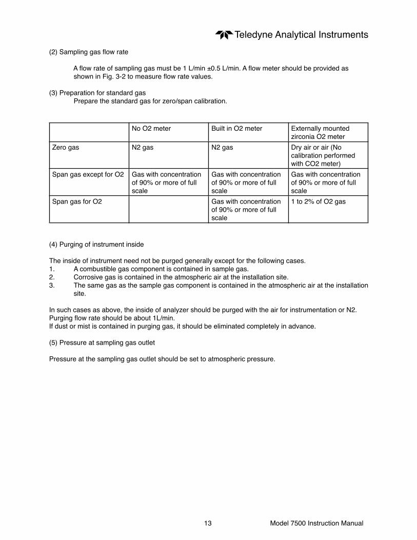
Teledyne Analytical Instruments(2) Sampling gas flow rate
A flow rate of sampling gas must be 1 L/min ±0.5 L/min. A flow meter should be provided as shown in Fig. 3-2 to measure flow rate values.
(3) Preparation for standard gas Prepare the standard gas for zero/span calibration.
No O2 meter Built in O2 meter Externally mounted zirconia O2 meter
Zero gas N2 gas N2 gas Dry air or air (No calibration performed with CO2 meter)
Span gas except for O2 Gas with concentration of 90% or more of full scale
Gas with concentration of 90% or more of full scale
Gas with concentration of 90% or more of full scale
Span gas for O2 Gas with concentration of 90% or more of full scale
1 to 2% of O2 gas
(4) Purging of instrument inside
The inside of instrument need not be purged generally except for the following cases.1. A combustible gas component is contained in sample gas.2. Corrosive gas is contained in the atmospheric air at the installation site.3. The same gas as the sample gas component is contained in the atmospheric air at the installation site. In such cases as above, the inside of analyzer should be purged with the air for instrumentation or N2.Purging flow rate should be about 1L/min.If dust or mist is contained in purging gas, it should be eliminated completely in advance.
(5) Pressure at sampling gas outlet
Pressure at the sampling gas outlet should be set to atmospheric pressure.

14 Model 7500 Instruction Manual
Teledyne Analytical Instruments(6) Example of sampling system configuration
The system configuration may vary depending upon the nature of measured gas, coexistent gases or application. A typical configuration diagram is shown in Fig. 3-2. Since a system configuration depends upon measured gas, consult with Teledyne.
Fig. 3-2 A typical example of sampling system

15 Model 7500 Instruction Manual
Teledyne Analytical Instruments
3.5 Wiring method
Caution on wiringCAUTION • Wiring work must be performed with the main
power set to OFF to prevent electric shocks.• Enforce construction of class-D grounding wire by all means.If the specified grounding construction is neglected, a shock hazard or fault may be caused.• Wires should be the proper one meeting the ratings of this instrument. If using a wire which cannot endure the ratings, a fire may occur.• Be sure to use a power supply of correct rating. Connection of power supply of incorrect rating may cause fire.
Each external terminal is provided on the rear panel of the analyzer. (See Fig. 3-3)Wire each terminal, referring to Fig. 3-3 and (1) to (7).
Fig. 3-3 Rear panel
(1) Power inletWhen using supplied power cable, connect the female side to the power inlet at the rear panel of the analyzer, and insert the male side into a receptacle matching the rating.

16 Model 7500 Instruction Manual
Teledyne Analytical Instruments
When a noise source is in the vicinityDo not install the analyzer near power noise generating electric equipment (such as high frequency furnace and electric welder). If the analyzer must be used near such equipment, a separate power line should be used for avoiding noise. In case noise may enter from a relay, solenoid valve, etc. through power supply, connect a varistor (such as ENA211-2 made by Fuji Electric) or spark killer (like S1201 made by OKAYA) to the noise source as shown below. If the varistor or spark killer is located away from the noise source, no effect is obtainable. So, locate near the noise source.
(2) Analog output signal (AO): terminal block 1 (1 to 10, 15 to 20) Output signal: 4 to 20 mADC or 0 to 1 VDC (selected when ordering) Non-insulated output Allowable load: 4 to 20 mADC, 550Ω or less 0 to 1 VDC, 100kΩ or less
• Analog output is provided from each terminal corresponding to the channel displayed in the measurement screen.
Note: All of analog output signals for the instrument are not isolated. It is recommended to isolate signals individually to prevent interference from unnecessary signals or to prevent external interference, especially leading the cable of more than 30 meters or to outdoor.
(3) O2 sensor input: terminal block 2 (1 – 2) Input signal: External zirconia O2 analyzer: Zirconia O2 sensor signal (Teledyne output) External O2 analyzer: 0 to 1 VDC (DC input resistor of 1MΩ or more)
• It is used when the external zirconia O2 analyzer or external O2 analyzer is specified as order.• To connect to the output of the external Zirconia analyzer or external O2 analyzer prepared separately.• In case of an external O2 analyzer, input a signal of 0 to 1 VDC with respect to O2 full scale of the analyzer.• In case of built-in O2 analyzer, do not use the terminals.
Note: O2 sensor input is not isolated. It is recommended to isolate input signal to prevent interference from unnecessary signals or to prevent external interference. Zirconia O2 sensor should be installed at a location that is as close to this instrument as possible.

17 Model 7500 Instruction Manual
Teledyne Analytical Instruments(4) Contact input (DI): terminal block 2 (13 to 20), terminal block 3 (5 to 10) • It is for a contact input at no voltage. An input is provided when switching to short circuit (on) or open (off). • No voltage is applied to the terminals
(5) Contact output (DO): terminal block 3 (13 to 20), terminal block 4 and terminal block 5 • Contact rating: 250VAC / 2A, load resistance • An output is for a relay contact output. An output is provided when switching to conductive (on) or open (off).
Note: The wires of analog output signals, O2 sensor input and contact input should be fixed separately from power supply wiring and contact output wiring.
(6) Communication interface: connector 2 • Please refer to the manual for communication function.

18 Model 7500 Instruction Manual
Teledyne Analytical Instruments(7) List of terminal blocks 1 to 5
*1) Unused terminals are used for internal connection and should not be used as repeating terminals either. *2) O2 sensor input is used when an external O2 analyzer is selected.

19 Model 7500 Instruction Manual
Teledyne Analytical Instruments
8) Description on terminal block
Terminal block 1 <TN1>Terminal block for analog output (non-isolated output)Output : 4 to 20 mA or 0 to 100V DCBetween 1 – 2: CH5 outputBetween 3 – 4: CH4 outputBetween 5 – 6: CH3 outputBetween 7 – 8: CH2 outputBetween 9 – 10: CH1 outputBetween 11 – 14: For internal connection. Must not be wired. (Must not be used as junction terminal.)Between 15 – 16: CH8 outputBetween 17– 18: CH7 outputBetween 19 – 20: CH6 output
Terminal block 2 <TN2>Between 1– 2: For O2 sensor input. (Input for our Zirconia oxygen sensor or external O2 sensor. Must not be used unless O2 meter is added.)Between 3 –12: For internal connection. Must not be wired. (Must not be used as junction terminal.)Between 13 – 14: CH4 remote range changeover inputBetween 15 – 16: CH3 remote range changeover inputBetween 17 – 18: CH2 remote range changeover inputBetween 19 – 20: CH1 remote range changeover input
Note: High range is selected when open. Low range is selected when short-circuited. For details of action, refer to “6.7 Parameters Setting, “Remote Range”.

20 Model 7500 Instruction Manual
Teledyne Analytical InstrumentsTerminal block 3 <TN3>
Between 1 – 4: For internal connection. Must not be wired. (Must not be used as junction terminal.)
Between 5 – 6: Remote hold input. No hold when open. Output hold when short-circuited.
Between 7 – 8: Average value reset input. Short- circuiting the contact input (for at 1.5 sec or more) resets O2 average and O2 correction average simultaneously. Opening it restarts the average value.
Between 9 – 10: Automatic calibration remote start input. Open input after strapping for at least 1.5 seconds starts the automatic calibration whether automatic calibration setting is ON or OFF.
Between 11 – 12: Conductive when analyzer unit error is producted. Normally open.
Between 13 – 14: CH4 range identification signal
Between 15 – 16: CH3 range identification signal
Between 17– 18: CH2 range identification signal
Between 19– 20: CH1 range identification signal
Note: Range identification signal is conductive at Low range or open at High range. In case of 1-range system, the signal remains open.

21 Model 7500 Instruction Manual
Teledyne Analytical InstrumentsTerminal block 4 <TN4>
Between 1 – 2: CH4 span calibration contact output
Between 3 – 4: CH3 span calibration contact output
Between 5 – 6: CH2 span calibration contact output
Between 7 – 8: CH1 span calibration contact
Between 9 – 10: Zero calibration contact output When the calibration contact output is measured with manual calibration, the calibration contact corresponding to calibration channel is conductive.
For the automatic calibration, they are worked sequentially according to “6.4 Auto calibration setting”. If calibration is not performed, all of them are open.
Between 11 – 12: For internal connection. Must not be wired. (Must not be used as junction terminal.)
Between 13 – 14: Automatic calibration in progress, contact output. Conductive during automatic calibration. Open otherwise.
Between 15 – 16: Calibration error contact output. Conductive when error is produced at zero or span calibration. Normally open.
Between 17 – 18: Pump ON/OFF contact output. (Used for turning ON/OFF the pump. Conductive during measurement and open at zero span calibration.)

22 Model 7500 Instruction Manual
Teledyne Analytical Instruments
Terminal block 5 <TN5>
1 and 11 – 14: For internal connection. Must not be wired. (Must not be used as junction terminal.)
Between 2 - 3 and 3 - 4: CH3 alarm output. Conductive at 2 – 3 and open at 3 – 4 when set value is exceeded. Open at 2 – 3 and conductive at 3 – 4 otherwise.
Between 5 - 6 and 6 - 7: CH2 alarm output. Conductive at 5 – 6 and open at 6 – 7 when set value is exceeded. Open at 5 – 6 and conductive at 6 – 7 otherwise.
Between 8 - 9 and 9 - 10: CH1 alarm output. Conductive at 8 – 9 and open at 9 – 10 when set value is exceeded. Open at 8 – 9 and conductive at 9 – 10 otherwise.
Between 15 - 16 and 16 - 17: Peak count alarm contact output. Conductive at 15 – 16 and open at 16 – 17 when preset peak count is exceed. Otherwise, open at 15 – 16 and conductive at 16 – 17. For setting and action, refer to instruction manual “6.6 Peak Alarm Setting”.
Between 18 – 19 and 19 – 20: CH4 alarm output. Conductive at 18 – 19 and open at 19 – 20 when set value is exceeded. Open at 18 – 19 and conductive at 19 – 20 otherwise.

23 Model 7500 Instruction Manual
Teledyne Analytical Instruments(9) Timing of calibration contact output
1. Manual calibration (See “6.9 Calibration”)
2. In case of automatic calibration (example shown in 6.4.1, Automatic calibration settings)
24 Model 7500 Instruction Manual
Teledyne Analytical Instruments
4. OPERATION
4.1 Preparation for operation
(1) Check of gas sampling tube, exhaust tube and wiring Check that the pipes are correctly connected to the gas sampling port and drain port. Check that the analyzer is correctly wired as specified.
4.2 Warm-up operation and regular operation
(1) Operation procedure
1. Turn ON the power switch at the left of the front panel. In one or two seconds, the measurement screen will appear at the front panel.
2. About 2 hour warm-up operation About 2 hours are needed until the operating performance is stabilized. Warm-up operation should be continued with the power ON.
3. Setting of various set values Set required set values according to Chapter 6, “Setting and calibration”.
4. Zero and span calibration Perform zero calibration and span calibration after warm-up operation. See Chapter 6.9, “Calibration”.
5. Introduction and measurement of measured gas Start measurement by introducing measured gas into the analyzer.
Note: While in warm-up operation, the concentration reading may be beyond the upper limit of the range (range-over) or below the lower limit. But this is not an error.

25 Model 7500 Instruction Manual
Teledyne Analytical Instruments
5. DISPLAY AND OPERATION PANELThis section describes the display and operation panel of the gas analyzer. It also explains the name and description of function on the operation panel. See Fig. 5-1.
5.1 Name and description of operation panel• Display: The measurement screen and the setting items are displayed.• Controls: The configuration is as shown below.
Name Description Name Description1. MODE key Used to switch the mode. 5. ESC key Used to return to a previous screen
or cancel the setting midway.2. SIDE key Used to change the selected
item (by moving the cursor) andnumeral digit.
6. ENT key Used for confirmation of selecteditems or values, and for execution of calibration.
3. UP key Used to change the selected item (by moving the cursor) and to increase numeral value.
7. ZERO key Used for zero calibration.
4. DOWN key Used to change the selected item (by moving the cursor) and to decrease numeral value.
8. SPAN key Used for span calibration.
Fig. 5-1 Name and description of operation display and panel
Note: The switch for back light is used for turning ON/OFF the back light of display. The life time of back light is 50,000 hours. Please turn OFF the switch when indicator is not necessary, so the life time will be longer.

26 Model 7500 Instruction Manual
Teledyne Analytical Instruments
5.2 Overview of display and operation panel
Figure 5.2

27 Model 7500 Instruction Manual
Teledyne Analytical Instruments
5.3 Overview of display screen
(1) Measurement mode screen
On turning on the power switch, the Measurement Mode screen will appear.
The measurement screen depends on the number of components. The following screen configuration shown as an example is for CO2, CO, O2 (Output at channel 6).
When channel 5 or later is displayed, scroll up or down key to view another configuration which is beyond the screen.
No. Name Function No. Name Description1 Component
displayDisplays component of instantaneous value, converted instantaneous value, converted average value, etc.
5 Peak alarm component display
Displays peak alarm component.
2 Concentration display
Displays measured value of concentration.
6 Peak alarm concentration display
Displays peak alarm concentration (Upper limit value).
3 Range display Displays range values.
7 Peak alarm count Displays the alarm times exceeding the peak value.
4 Unit display Displays unit with ppm and vol%.
8 Peak alarm unit display
Displays unit of peak alarm with times/h.
Fig. 5-3 Name and function of measurement mode screen
• Instantaneous value and concentration value:The concentration display of CH (component) where sampling components such as “CO2”, “CO” or “O2 are displayed in the component display, indicates current concentration values of the measured components contained in gas that is now under measurement.
• O2 correction concentration values:CH (components) where “cv**” is displayed as “cv CO” in the component display are calculated from the following equation, by setting sampling components, O2 instantaneous / concentration values and O2 correction reference value (see item 6.8).
Conversion output=
On: The value of the O2 correction reference value (Value set by application)Os: Oxygen concentration (%)Cs: Concentration of relevant measured componentK: The value of the fractional part is this equation. Where, K is When K ≥ 4, K=4. When K < 0, K=4. When Cs < 0, K=0.The correction components are CO and SO2 only.

28 Model 7500 Instruction Manual
Teledyne Analytical Instruments• O2 correction concentration average value:
CH (component) where “AV / CV” is displayed as “AV / CV CO” in the component display and O2 average value, a value obtained by averaging O2 conversion concentration value or O2 concentration value in a fixed time is output every 30 seconds.
Averaging time can be changed between 1 minute and 59 minutes or 1 hour and 4 hours according to the average time settings (See 6.7 Parameter setting).
(The set time is displayed as “1h”, for instance, in the Range display.)
* The measurement ranges of O2 correction concentration value and O2 correction concentration average value are the same as that of the measuring components. Also, the measurement range of O2 average value is the same as that of O2.
(2) Setting/selection screen
The setting/selection screen is configured as shown below:
• In the status display area, the current status is displayed.• In the message display area, messages associated with operation are displayed.• In the setting item and selection item display area, items or values to be set are displayed, as required. To work on the area, move the cursor to any item by using up, down, and right keys.
Figure 5-4: Display screen

29 Model 7500 Instruction Manual
Teledyne Analytical Instruments(3) Contents of measured channel (CH)
The contents in each measured CH corresponding to the type are given below:
Type code Contents5th digit
6th digit 7th digit
CH1 CH2 CH3 CH4 CH5 CH6 CH7Y C Y O2A Y Y SO2B Y Y COD Y Y CO2E Y Y CH42 Y Y CO2 CO3 Y Y CH4 CO4 Y Y CO2 CH45 Y Y CO2 CO CH4A A, B, C Y SO2 O2B A, B, C Y, B CO O2D A, B, C Y CO2 O2E A, B, C Y CH4 O22 A, B, C Y, B CO2 CO O23 A, B, C Y, B CH4 CO O24 A, B, C Y CO2 CH4 O25 A, B, C Y CO2 CO CH4 O2A A, B, C A SO2 O2 Corrected
SO2Corrected SO2 average
O2 average
B A, B, C A, C CO O2 Corrected CO
Corrected CO average
O2 average
2 A, B, C A, C CO2 CO O2 Corrected CO
Corrected CO average
O2 average
3 A, B, C A, C CH4 CO O2 Corrected CO
Corrected CO average
O2 average
5 A, B, C A, C CO CO CH4 O2 Corrected CO
Corrected CO average
O2 average
How to view the TableWhen SO2 is displayed in CH1, it means that display and output of CH1 correspond to SO2 component.

30 Model 7500 Instruction Manual
Teledyne Analytical Instruments
5.4 General operation
• Measurement modeThe measurement mode can be displayed for up to 5 channels in a single screen. When viewing a channel beyond the 5 channels, press the ( or ) key and the screen can be scrolled one by one channel at a time.
• User mode displays the following settings
Changeover of range
Calibration setting
Alarm setting
Setting of auto calibration
Setting of auto zero calibration
Peak alarm setting
Parameter setting
For settings, refer to “6, Setting and Calibration.”

31 Model 7500 Instruction Manual
Teledyne Analytical Instruments
6. SETTING AND CALIBRATION
6.1 Changeover of range
This mode is used to select the ranges of measured components.
1. During measurement, press the MODE key to display the User mode.
2. Point the cursor to “Changeover of Range”. Press the ENT key.
3 The “Channel Selection” screen appears. Press the UP or DOWN key until the cursor moved selects a desired CH (component).
4. After selection, press the ENT key.
Note: The range of O2 correction instantaneous values and O2 correction average values is automatically switched by changing the range of instantaneous value of each CH (component).
5. In the Range Setting screen that appears, move the cursor by pressing the UP or DOWN key to select the range. (The range with a TRIANGLE mark is currently selected.)
6. After selection, press the ENT key.
7. Measurement is conducted within the selected range. The range identification signal (CO) is shorted with the low range (Range 1), and open with the high range (Range 2).
Note: If the Remote Range is set to ON, the changeover of range cannot be performed on the screen.
To close Changeover of range
To close Changeover of range, or cancel the command midway, press the ESC key. A previous screen will return.

32 Model 7500 Instruction Manual
Teledyne Analytical Instruments
6.2 Calibration setting
This mode is used to set calibration concentration and actions. The calibration setting involves calibration concentration, zero calibration, calibration range and auto-calibration component.
6.2.1 Setting of calibration concentrationIt allows you to set concentrations of the standard gas (zero and span) of each channel used for calibration.
1. During measurement, press the MODE key to display the User mode.
2. Point the cursor to “Setting about Calibration” by pressing the UP or DOWN key. Press the ENT key.
3. In the “Setting about Calibration” screen that appears, point the cursor to “Calibration Value” by pressing the UP or DOWN key. Press the ENT key.
4. In the “Calibration Concentration CH Selection” screen that appears, point the cursor to CH you want to set by using the UP or DOWN key. Press the ENT key.

33 Model 7500 Instruction Manual
Teledyne Analytical Instruments5. In the “Calibration Concentration Selection” screen that appears, select any concentration item you want to set by pressing the UP, DOWN, and RIGHT key.
Note: Analyzers other than the zirconia O2 instrument cannot perform zero setting.
6. In the “Calibration Concentration Value Setting” screen that appears, enter calibration gas concentration values (zero and span). For value entry, press the UP or DOWN key, and a 1-digit value increases or decreases. By pressing the RIGHT key, the digit moves.
After setting, save the entry by pressing the ENT key. The saved value becomes valid from the next calibration process.
Note: Enter the set values corresponding to each range. When the O2 measurement uses atmospheric air for the zero gas, set the concentration value to 21.00. When the cylinder air is used, set to the concentration value as indicated on the cylinder.
To close the settingTo close the calibration concentration value setting process or cancel this mode midway, press the ESC key. A previous screen will return.
Setting range of valuesParamagnetic O2, CO2, CO, SO2 and CH4 measurement: Zero gas: Fixed at 0 Span gas: Minimum digit, 1 to 100% of full scale (Full scale (FS) is the same as each range value.)
Zirconia O2 measurement : Zero gas: 5 to 25 vol% Span gas: 0.01 to 5 vol%
The setting cannot be performed beyond the range.

34 Model 7500 Instruction Manual
Teledyne Analytical Instruments6.2.2 Setting of manual zero calibrationIf zero calibration is to be made manually, select whether to calibrate all components at once or each of them separately upon selection.
1. During measurement, press the MODE key to display the User mode.
2. Point the cursor to “Setting about Calibration” by pressing the UP or DOWN key. Press the ENT key.
3. In the “Setting about Calibration” screen that appears, point the cursor to “About ZERO Calibration” by pressing the or key. Press the ENT key.
4. In the “Manual Calibration CH Selection” screen that appears, point the cursor to CH you want to set by using the UP or DOWN key. Press the ENT key.

35 Model 7500 Instruction Manual
Teledyne Analytical Instruments5. In the “Manual Calibration Selection” screen that appears, select “At once” or “Each” by pressing the UP or DOWN key. When selecting “Both”, the CH (components) to be set can be zero-calibrated at the same time. When selecting “Each”, either of the CH (components) to be selected is zero-calibrated. After setting, press the ENT key, and the calibration you specified is carried out.
To close “About ZERO Calibration”
To close “About ZERO Calibration” setting or to cancel this mode midway, press the ESC key. A previous screen will return.
EXAMPLEWhether upon selection or at once can be determined for each CH (component).
•Setting upon selection Select the CH (component) and then perform zero calibration on the manual zero calibration screen.
•Setting at once At a manual zero calibration, CHs (components) for which “at once” was selected can simultaneously be calibrated.
* When the zirconia O2 analyzer uses the cylinder air or atmospheric air for the zero gas, select “At once”.
Manual Calibration screen

36 Model 7500 Instruction Manual
Teledyne Analytical Instruments6.2.3 Setting of calibration range
This mode is used to set if the range of each CH (component) at the calibration manual calibration or auto calibration) should be calibrated with a single range or 2 ranges.
1. During measurement, press the MODE key to display the User mode.
2. Point the cursor to “Setting about Calibration” by pressing the UP or DOWN key. Press the ENT key.
3. In the “Setting about Calibration” screen that appears, point the cursor to “About Calibration Range” by pressing the UP or DOWN key. Press the ENT key.
4. In the “Calibration Range CH Selection” screen that appears, point the cursor to the CH you want to set by pressing the UP or DOWN key. Press the ENT key.
37 Model 7500 Instruction Manual
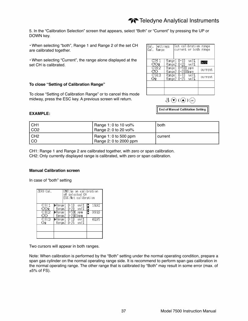
Teledyne Analytical Instruments5. In the “Calibration Selection” screen that appears, select “Both” or “Current” by pressing the UP or DOWN key.
• When selecting “both”, Range 1 and Range 2 of the set CH are calibrated together.
• When selecting “Current”, the range alone displayed at the set CH is calibrated.
To close “Setting of Calibration Range”
To close “Setting of Calibration Range” or to cancel this mode midway, press the ESC key. A previous screen will return.
EXAMPLE:
CH1CO2
Range 1: 0 to 10 vol%Range 2: 0 to 20 vol%
both
CH2CO
Range 1: 0 to 500 ppmRange 2: 0 to 2000 ppm
current
CH1: Range 1 and Range 2 are calibrated together, with zero or span calibration.CH2: Only currently displayed range is calibrated, with zero or span calibration.
Manual Calibration screen
In case of “both” setting
Two cursors will appear in both ranges.
Note: When calibration is performed by the “Both” setting under the normal operating condition, prepare a span gas cylinder on the normal operating range side. It is recommend to perform span gas calibration in the normal operating range. The other range that is calibrated by “Both” may result in some error (max. of ±5% of FS).

38 Model 7500 Instruction Manual
Teledyne Analytical Instruments6.2.4 Setting of auto-calibration component
It sets the CH (component) to be calibrated in the auto-calibration.
1. During measurement, press the MODE key to display the User mode.
2. Point the cursor to “Setting about Calibration” by pressing the UP or DOWN key. Press the ENT key.
3. In the “Setting about Calibration” screen that appears, point the cursor to “Auto Calibration Components” by pressing the UP or DOWN key. Press the ENT key.
4. In the “Auto Calibration Components” selection screen that appears, point the cursor to the CH you want to set by pressing the UP or DOWN key. Press the ENT key.

39 Model 7500 Instruction Manual
Teledyne Analytical Instruments5. In the “Auto Calibration Selection” screen that appears, select “enable” or “disable” by pressing the UP or DOWN key. After setting, press the ENT key.
To close Auto Calibration Component setting
To close “Setting of Auto Calibration Component” or to cancel this mode midway, press the ESC key. A previous screen will return.
ExampleAuto calibration is made in the following rules according to the setting. 1. Zero calibration at once of CHs (components) which were set to “enable”. 2. The span of CHs (components) which were set to “enable” is calibrated in the ascending order of CH number.
Example 1. In case all of CH1: CO2, CH2: CO, CH3: O2, were set to “enable”.Zero calibration (at once) of CH1 to CH3 n span calibration of CH1 (CO2) nspan calibration of CH2 (CO) n span calibration of CH3 (O2)
Example 2. In case, out of CH1: CO2, CH2: CO and CH3: O2, CH1 ( CO2) was set to “enable”,CH2 (CO) was set to “enable” an CH3 (O2) was set to “disable”.Zero calibration (at once) of CH1 and 2 n span calibration of CH1 (CO2) nspan calibration of CH2 (CO)
CAUTIONThe components which were set to “enable” is calibrated to zero at once at the time of auto calibration regardless of setting in “6.2.2 Setting of manual zero calibration”.

40 Model 7500 Instruction Manual
Teledyne Analytical Instruments
6.3 Alarm setting
6.3.1 Setting of alarm valuesThis mode is used to set the upper and lower limit value to provide an alarm output during measurement. Before changing the alarm setting, set the ON/OFF to OFF.
1. During measurement, press the MODE key to display the User mode.
2. Point the cursor to “Alarm Setting” by pressing the UP or DOWN key. Press the ENT key.
3. After the alarm setting CH selection screen has appeared, operate the UP or DOWN key until the cursor is aligned with a desired CH and press the ENT key.
4. After the alarm item selection screen has appeared, operate the or key until the cursor is aligned with a desired item and press the ENT key.
CAUTIONSet the values so that upper limit value > lower limit value and that (upper limit value - lower limit value) > hysteresis error.
The alarm is activated in each range independently from the settings of each range.

41 Model 7500 Instruction Manual
Teledyne Analytical InstrumentsAfter setting, the alarm setting is now completed by pressing the ENT key.
To close the “Alarm Setting”To close the “ Alarm Setting” or to cancel this mode midway, press the ESC key.A previous screen will return.
Setting range0 to 100% FS (Settable in each range).
Description of setting items
Upper limit value: Sets the upper limit value (concentration) of alarm.Lower limit value: Sets the lower limit value (concentration) of alarm.Contact action: Selects one of upper limit alarm, lower limit alarm, and upper limit or lower limit alarm. Upper limit alarm ... Alarm contact operates when above upper limit value. Lower limit alarm ... Alarm contact operates when below lower limit value. Upper limit alarm or lower limit alarm ...Alarm contact operates when above upper limit value or below lower limit value.
ON/OFF: Enables the alarm function if set at ON, or disables the alarm function if set at OFF.
* The upper limit value cannot be set below the lower limit value, and the lower limit value cannot be set above the upper limit value.
If it is desired to set the upper limit value below the lower limit value already stored in the memory, reduce the lower limit value beforehand, or vice versa.
Typical on-screen display when an alarm occurs
When an upper limit alarm has occurred, the “High alarm” message lights at CH (component)(“Low alarm” at lower limit alarm).
CAUTION
For 10 minutes after turning on power, the alarm judgment is inactive.

42 Model 7500 Instruction Manual
Teledyne Analytical Instruments6.3.2 Hysteresis settingTo prevent chattering of an alarm output near the alarm setting values, set hysteresis.
1. In the “Alarm Setting CH Selection” screen that appears, point the cursor to “Hysteresis” by pressing the UP or DOWN key. Press the ENT key.
2. In the “Hysteresis Value Setting” screen that appears, enter hysteresis values. For the value entry, 1-digit value is increased or decreased by pressing the UP or DOWN key, and pressing the RIGHT key moves the digit. After setting, press the ENT key to carry out hysteresis.
To close Hysteresis Setting
To close the “Hysteresis Setting” or cancel the mode midway, press the ESC key. A previous screen will return.
Setting range
0 to 20% of full scaleA full scale means each range provides a full scale of width.
CautionThe hysteresis is common to all CHs (components).
Hysteresis
If hysteresis values exceed the upper limit value as shown in graph, an alarm output is provided. Once the alarm output is turned ON, it remains ON until the value falls below the set lower limit of the hysteresis indication.

43 Model 7500 Instruction Manual
Teledyne Analytical Instruments
6.4 Setting of auto calibration
6.4.1 Auto calibration
Auto calibration is automatically carried out when zero calibration and span calibration are set.
Before changing the setting of auto calibration, set the ON/OFF to OFF.
1. During measurement, press the MODE key to display the User mode.
2. Point the cursor to “Setting of Auto Calibration” by pressing the or key. Press the ENT key.
3. In the “Setting of Auto Calibration” screen that appears, point the cursor to any item you want by pressing the UP or DOWN key. Press the ENT key.
4. In the “Auto Calibration Parameter Setting” screen that appears, perform the value entry or the setting. For the value entry or setting change, use the UP or DOWN key. For the value entry and setting, use the UP or DOWN key. To change the setting, use the RIGHT key to move the cursor to the right.
After setting, press the ENT key, and auto calibration is carried out by the entered setting value.
Description of setting items
• Start Time: Setting at the first calibration (day of the week, hour, minute)
• Cycle: A period between the start time of one calibration and another (unit : hour/day)
• Flow Time: The time required for the calibration gas to be replaced in the cell
• ON/OFF: Auto zero calibration ON or OFF
To close Setting of Auto calibration
To close the “Setting of Auto calibration” or cancel this mode midway, press the ESC key. A previous screen will return.

44 Model 7500 Instruction Manual
Teledyne Analytical InstrumentsAuto calibration status contact output is closed during auto calibration, and is open in other cases.
Setting rangeCycle: 1 to 99 hours or 1 to 40 days (initial value 7 days)Flow time: 60 to 599 sec (initial value 300sec)
CAUTION
When an auto calibration starts, the measurement screen automatically appears.
Any operation other than forced stop of auto calibration (see Item 6.4.2) is not permitted during auto calibration. “Auto Calibration Cancel” cannot be performed with the key lock to ON. To cancel auto calibration forcedly, set the key lock to OFF and then execute “Auto Calibration Cancel”.
Remote startWhether the auto calibration is set at ON or OFF, an auto calibration is available by keeping the remote start input short-circuited for at least 1.5 seconds.

45 Model 7500 Instruction Manual
Teledyne Analytical Instruments6.4.2 Forced stop of auto calibration
This mode is used to cancel the auto calibration forcedly.
1. In the Menu mode that is displayed, point the cursor to “Setting of Auto Calibration” by pressing the UP or DOWN key. Press the ENT key.
2. In the “Setting of Auto Calibration” item selection screen that appears, point the cursor to “Setting of Auto Calibration” by pressing the UP or DOWN key. Press theENT key.
3. “Stop Auto Calibration” is inverted. A message appears, prompting you to verify that you want to cancel or continue auto calibration. To cancel the auto calibration, press the ENT key. If you press the ESC key, auto calibration is not stopped.

46 Model 7500 Instruction Manual
Teledyne Analytical Instruments“Auto Calibration” screen
ExampleIn case where setting the auto calibration components (see Item 6.2.4) to “CH1: enable” and “CH2: enable”.
• Zero calibration A message, “Zero calibration” blinks at CH1 and CH2.
• CH1 span calibrationA message, “Span calibration” blinks at CH1.
• CH2 span calibrationA message, “Span calibration” blinks at CH2.
CAUTION
During auto calibration, any key operation is not permitted other than operations such as key lock ON/OFF and “Stop Auto Calibration”. When the key lock is set at ON, even the “Stop Auto Calibration” cannot be used. To stop “Auto Calibration” forcedly, set the key lock to OFF and then execute “Stop Auto Calibration”.

47 Model 7500 Instruction Manual
Teledyne Analytical Instruments
6.5 Setting of auto zero calibration
6.5.1 Auto zero calibration
Auto zero calibration is automatically carried out when zero calibration are set.
Components for which a calibration is to be made are determined by setting of auto calibration component in 6.2.4.
Before changing the setting of auto zero calibration, set the ON/OFF to OFF.
1. During measurement, press the MODE key to display the User mode.
2. Point the cursor to “Setting of Auto Zero Calibration” by pressing the UP or DOWN key. Press the ENT key.
3. In the “Setting of Auto Zero Calibration” screen that appears, point the cursor to any item you want by pressing the UP or DOWN key. Press the ENT key.
4. In the “Auto Zero Calibration Parameter Setting” screen that appears, perform the value entry or the setting. For the value entry or setting change, use the UP or DOWN key. To change the setting, use the RIGHT key to move the cursor to the right.
After setting, press the ENT key, and auto zero calibration is carried out by the entered setting value.
Description of setting items
• Start Time: Setting at the first calibration (day of the week, hour, minute)• Cycle: A period between the start time of one calibration and another (unit : hour/day)• Flow Time: The time required for the calibration gas to be replaced in the cell• ON/OFF: Auto zero calibration ON or OFF
To close “Auto Zero Calibration”
To close the “ Auto Zero Calibration “ or cancel this mode midway, press the ESC key. A previous screen will return.

48 Model 7500 Instruction Manual
Teledyne Analytical InstrumentsAuto calibration status contact output is closed during auto zero calibration, and is open in other cases.
Setting rangeCycle: 1 to 99 hours or 1 to 40 days (initial value 7 days)Flow time: 60 to 599 sec (initial value 300 sec)
Caution
• When an auto zero calibration starts, the measurement screen automatically appears.
• Any operation other than forced stop of auto zero calibration (see Item 6.5.2) is not permitted during auto zero calibration. “Auto Zero Calibration Cancel” cannot be performed with the key lock to ON. To cancel auto zero calibration forcedly, set the key lock to OFF and then execute “Auto Zero Calibration Cancel”.
• If the auto calibration period and auto zero calibration period have overlapped, the auto calibration is retained, ignoring the auto zero calibration of that period.

49 Model 7500 Instruction Manual
Teledyne Analytical Instruments6.5.2 Forced stop of auto zero calibration
This mode is used to cancel the auto zero calibration forcedly.
1. In the Menu mode that is displayed, point the cursor to “Setting of Auto Zero Calibration” by pressing the UP or DOWN key. Press the ENT key.
2. In the “Setting of Auto Zero Calibration” item selection screen that appears, point the cursor to “Setting of Auto Zero Calibration” by pressing the UP or DOWN key. Press the key.
3. “Stop Auto Zero Calibration” is inverted. A message appears, prompting you to verify that you want to cancel or continue auto zero calibration. To cancel the auto zero calibration, press the ENT key. If you press the ESC key, auto zero calibration is not stopped.

50 Model 7500 Instruction Manual
Teledyne Analytical Instruments“Auto Zero Calibration” screen
ExampleIn case where setting the auto calibration components (see Item 6.2.4) to “CH1: enable” and “CH2: enable”.
• Zero calibration A message, “Zero calibration” blinks at CH1 and CH2.
CAUTION
During auto zero calibration, any key operation is not permitted other than operations such as key lock ON/OFF and “Stop Auto Zero Calibration”.
When the key lock is set at ON, even the “Stop Auto Zero Calibration” cannot be used. To stop “Auto Zero Calibration” forcedly, set the key lock to OFF and then execute “Stop Auto Zero Calibration”.

51 Model 7500 Instruction Manual
Teledyne Analytical Instruments
6.6 Peak alarm settingWhen the number of peaks of which CO concentration exceeds the upper limit value exceeds the setting time, a peak alarm is outputted.
This section describes how to perform various settings of peak alarm.
Note: The setting is optional and is valid only when peak alarm function is provided.
1. Press the MODE key in the Measurement mode, and the User mode appears.
2. Point the cursor to “Setting of Peak Alarm” by pressing the or key. Press the ENT key.
3. In the “Peak Alarm Setting” item selection screen that appears, point the cursor to any item you want by pressing the UP or DOWN key. Press the ENT key.
4. Then, enter numeric values and perform the setting.
Entering or setting the numeric values should be carried out by using the UP or DOWN key.
After setting, press the ENT key, and the set values you entered are saved.
Description of setting items
• Peak Alarm: Setting of peak alarm is performed with ON/OFF.
• Alarm value: If peak concentrations exceed the set alarm value, a peak counter counts 1 time.
• Alarm Count: When a peak in excess of the setting time occurs, a peak count alarm output is provided.
• Hysteresis: To prevent possible chattering when the peak value may exceed the set peak concentration by only 1 time, the peak count has an allowance in the hysteresis width.

52 Model 7500 Instruction Manual
Teledyne Analytical InstrumentsSetting range
• Alarm Value: 0 to 1000 ppm 5 ppm step (initial value: 500 ppm)• Alarm Count: 1 to 99 times (initial value: 5 times)• Hysteresis: 0 to 20% of full scale (initial value: 0% of full scale) * The hysteresis setting is made in terms of full scale.
Action of peak alarm
If CO concentration exceeds the alarm value, counting will begin. If the number of peaks is over the set times per hour, a peak count alarm becomes closed (ON). If it is less than the set times per hour, it is open (OFF). Since 5 times of peaks /hour is marked at 1 section from the above graph, the peak count alarm is turned ON. Since peaks of more than 5 times per 1 hour occur at the interval between 1 and 2 , the peak count alarm remains ON. Since peaks are reduced to 4 times per hour, it is turned OFF.
Like the hysteresis of the alarm setting , the hysteresis prevents possible chattering when measured gas is fluctuated near the alarm value.
* For 10 minutes after the power is turned ON, a peak alarm counting is not carried out.
Releasing peak alarm To release the peak alarm, set the peak alarm to OFF. Turning on the peak alarm initiates counting from 0.

53 Model 7500 Instruction Manual
Teledyne Analytical Instruments
6.7 Parameter setting
It allows you to carry out the parameter setting such as time, key lock, etc., as required. Items to be set are as follows:
Description of setting items
• Current Time: Sets the current day of the week, hour and time.• Key Lock: Sets with ON/OFF so that any key operation except the key lock OFF cannot be performed.• Remote Range: Sets with ON/OFF whether the Range Selection is made valid or invalid by external input.• Output Hold: Sets whether Calibration Output is held or not.• Average Value Reset: Resets the average value.• Response Speed: Sets the response time of electrical system.• Average Time: Sets the moving average time.• Maintenance mode: Enters passwords to switch to the Maintenance mode.
* For the maintenance mode, see Item 6.8.
1. To display the User mode, press the MODE key in the measurement mode.
2. Point the cursor to “Parameter Setting” by pressing the or key. Press the ENT key.
3. In the “Parameter Setting” screen that appears, point the cursor to any item you want by pressing the or key. Press the ENT key.

54 Model 7500 Instruction Manual
Teledyne Analytical Instruments4. In the Parameter Setting screen that appears, enter the numeric values and set the items. Entering the numeric values or setting the items should be carried out by using the or key. To move the cursor to the right, press the key.
After setting, press the ENT key, that the parameter setting is carried out with the value you set.
To close Parameter Setting screen
To close the “Parameter Setting” screen or cancel this mode midway, press the ESC key. A previous screen will return.
Setting Range
• Response time: 1 to 60 sec. (Initial value: 3 sec)• Average time: 1 to 59 min or 1 to 4 hours (Initial value: 1 hour) When setting the unit of 1 to 59 minutes in terms of minute or 1 to 4 hours with hour• Maintenance mode: 0000 to 9999 (Initial value: 0000)
Remote RangeA range can be switched via an external input by setting the Remote Range to ON. (The switching action affects all of instantaneous value, O2 correction value, O2 correction average value and O2 average value.) If the Remote Range is set to OFF, the external input becomes invalid.
Opening the input gives the High range, or short-circuiting the input gives the Low range.For the terminal input, refer to 3.4, Wiring.
Switching the range cannot be performed by on-screen operation when the REMOTE RANGE is set to ON.
Note: In case of 1 range system, this function is overridden.
Output HoldBy setting an output hold to ON, an output signal of each channel are held during the calibration (manual calibration and auto calibration) and for the gas flow time (refer to 6.4, Setting of Auto Calibration). Regardless of Hold ON/OFF setting, an output signal can be held via an external input.
(1) Manual calibration

55 Model 7500 Instruction Manual
Teledyne Analytical Instruments(2) Auto calibration
(3) External hold
(4) Screen display during holding
The “Holding” message blinks on the measuring screen.
Since the screen displays the process of calibration is displayed during the manual calibration, “Holding” is not displayed even if the screen is held, but the screen is displayed with the hold extending time.
(5) If calibration is cancelled after the calibration gas is supplied regardless of during manual calibrationor auto calibration, an output hold of the holding extending time will be performed.
Average value reset
This mode is used to clear O2 correction average value and O2 average value, and restarts averaging. All average values are reset at a time. The indication value and output value is 0 ppm, vol% or so at the time of the reset input.
So long as short-circuited, resetting lasts.At the edge of changing from short circuit to opening, the average action restarts.
Response timeThe response time of the electrical system can be changed.Setting is available by components.
Note: It does not provide exact seconds for the setting time, but it gives a guide of the setting time. The setting value can be modified as requested by the customer.

56 Model 7500 Instruction Manual
Teledyne Analytical InstrumentsAverage period
It allows you to set an average period of the average value of O2 correction.
It enables you to set an average time of 1 to 59 minutes (1-minute step) or 1 to 4 hours (1-hour step).
Changing the setting resets the average value of O2 correction and O2 average value. (Pressing the ENT validates the resetting only for components whose setting was changed.)
Example of average action
Suppose the average period is 1 hour.
• Sampling occurs every 30 seconds
• Every 30 seconds, the average for last 1 hour (time setting) is output.
• At the instant of resetting, zero is assumed for all past values. It means the average value will not be correct for 1 hour after resetting.
Maintenance modeTo open the maintenance mode, enter a password. After entering the password, press the ENT key.
The password can be used for the Password Setting in the Maintenance mode. A password is set to “0000” before factory-shipment. This value is available for the Maintenance mode.

57 Model 7500 Instruction Manual
Teledyne Analytical Instruments
6.8 Maintenance mode
This mode is used for check of sensor input values, display of error log files or setting of passwords. First, enter a password and then use it from the next operation. This mode is displayed by selecting the Maintenance Mode from “6.7 Parameter Setting”
1. Select the Maintenance mode from the Parameter Setting screen to display the Password Setting screen.
2. Enter the password, and the Maintenance Mode item selection screen will be displayed. Point the cursor to the item you want by pressing the or key and press the ENT key.
3. Next, each Maintenance screen is displayed.
Note: “To Factory Mode” is used for our service engineers only. Refrain from using this mode.
• Sensor Input Value screen
Description of Sensor Input Value screen
• CO2: CO2 sensor input value• CO: CO sensor input value• O2: O2 sensor input value• Temperature : Temperature sensor input value
• Error Log screen
Description of Error Log screen
Error historyFor error number, date and time (days, period) of occurrence, channel and other details of error, refer to “8.1 Error message”.

58 Model 7500 Instruction Manual
Teledyne Analytical Instruments• O2 correction reference value setting screen
• Password Setting screen
Description of Password Setting screen
It enables you to set a password to be used when switching the parameter setting mode to the maintenance mode.
Note: The password set herein must be managed for safety. Failure to enter the correct password will not open the Maintenance mode.
• Station No. setting screen (option)
Setting range
• Station No.: 00 to 31 (Initial No.: 00)
* Please refer to another manual (INZ-TN513327-E) about the communication function.

59 Model 7500 Instruction Manual
Teledyne Analytical Instruments
6.9 Calibration
6.9.1 Zero calibration
It is used for zero point adjustment. For zero calibration gas, see 3.3 (3), Preparation for standard gas in Sampling. Use a gas according to application.
1. Press the ZERO key on the Measurement screen to display the Manual Zero Calibration screen.
2. Select the CH (component) to be calibrated by pressing the UP or DOWN key. After selection, press the ENT key, and zero gas will be supplied.
CAUTION
For the CH (components) that is set to “at once” in the “Zero Calibration” of the Calibration Setting mode, zero calibration is also carried out at the same time.
3. Wait until the indication is stabilized with the zero gas supplied. After the indication has been stabilized, press the ENT key. Zero calibration in Range selected by the cursor is carried out.
To close Zero Calibration
To close the “Zero Calibration “ or cancel this mode midway, press the ESC key. A previous screen will return.

60 Model 7500 Instruction Manual
Teledyne Analytical Instruments6.9.2 Span calibration
It is used to perform a span point adjustment. Supply calibration gas with concentration set to the span value to perform the span calibration. For the span calibration gas for the SO2, CO2, CO, H4 measurement, use the standard gas with a concentration of 90% or more of the range value. For the calibration gas for the O2 measurement, use the standard gas of about 2 vol%.
1. Press the SPAN key on the Measurement screen to display the Manual Span Calibration screen.
2. Press the UP or DOWN key to select CH (component) to be calibrated. After selection, press the ENT key, and the span calibration contact output on corresponding to CH is turned ON. And supply span gas.
CAUTION
When Range Interlock from “Calibration Range” of the Calibration Setting mode is set, span calibration is performed together with 2 Ranges.
3. Wait until the indication is stabilized in the state where the calibration gas is supplied. After the indication has been stabilized, press the ENT key. Span calibration of Range selected by the cursor is performed.
To close Span Calibration
To close the “ Span Calibration “ or cancel this mode midway, press the ESC key. A previous screen will return.

61 Model 7500 Instruction Manual
Teledyne Analytical Instruments
7. MAINTENANCE
7.1 Daily check(1) Zero calibration and span calibration 1. It is used for zero point adjustment. For calibration, refer to 6.9.1, Zero calibration. 2. After zero calibration, perform span calibration. For calibration, refer to 6.9.2, Span calibration. 3. Zero calibration and span calibration should be performed once a week, if required.
(2) Flow check
1. Sampling gas flow rate and purge gas flow rate should be as follows; Sampling gas flow rate: 1.0 L / min ±0.5 L / min (stable) Purge gas flow rate: About 1L / min
2. Maintenance and check should be carried out every day, if required.
7.2 Daily check and maintenance procedures
Table 7-1 Maintenance and check list
Parts to be checked Phenomena Cause RemedyEvery day Recorder indication Lower indication 1. Dust is mixed in
the sample cell1. Clean sampling cell and check for sampling device, especially gas filter
2. Air is sucked in anywhere in the sampling tube
2. Check for leak of the sampling line and repair if required
Check for purge gas flow if purging the sampling gas flow instrument
Standard flow rate is 1L / min. It is not within the range of the specified flow rate of 0.5 to 1.5 L / min.
Adjust the flow rate with flow rater needle valve
Replacement of Monitor filter (membrane filter)
Much clogged Primary filter is damaged
1. Replace primary filter2. Replace filter (paper)
Every week Zero point of gas analyzer
Out of zero point Zero calibration
Span point of gas analyzer
Out of the standard point
Span calibration
Replacement of monitor filter (membrane filter)
Irrespective of phenomena
Replace filter (paper)
Every year Gas analyzer Irrespective of phenomena
Overhaul

62 Model 7500 Instruction Manual
Teledyne Analytical Instruments
7.3 Cleaning of measuring cellEntry of dust or water drops in the measuring cell contaminates the interior of the cell, thus resulting in a drift. Clean the inside if dirty. Then, check the sampling device, especially the filter, to prevent the cell from being contaminated by dust or mist.
7.3.1 Disassembly and assembly of measuring cell
There are two kinds of measuring cells, on block cells (cell length: 4 mm, 8 mm, 16 mm, 32 mm) and pipe cells (Cell length: 6.4 mm, 125 mm and 250 mm). 2-component analyzer may incorporate both measuring cells in optical unit. In such a case, detach the pipe cell and then block cell (See Fig. 7-1).
(1) How to remove pipe cell (See Fig. 7-1)
1. Stop measured gas. If it is harmful, purge in the measuring cell thoroughly with zero gas.
2. Turn OFF the power switch.
3. Detach the top cover. 4. Remove the pipe connected to the measuring cell.
5. Slide the infrared ray light source unit (No. 5) toward the front panel by loosening the screw (No. 1) fastened to the base plate to provide clearance between the pipe cell (No. 12) and light source unit.
6. Loosen and remove a screw (No. 7) from the cell retainer (No. 11) fastening the pipe cell.
7. Remove the cell from the measuring unit and unscrew the infrared transmission window (No. 14) at the both ends in the right direction.
Note: The reflection plate in the cell is not closely attached to the cell.
8. For assembly, reverse the disassembly procedure. Provide 0.5 mm clearance between the infrared ray light source unit and cell, and the cell and detector, respectively.

63 Model 7500 Instruction Manual
Teledyne Analytical Instruments
Number Name1 Screw (for fixing light source unit)2 Screw (for fixing detector)3 Screw (for fixing base plate)4 Base plate5 Light source unit6 Screw (for fixing support)7 Screw (for fixing cell retainer)8 Chopper motor connector(9) Filter10 Support11 Cell retainer12 Pipe cell13 O-ring14 Infrared transmission window15 Detector16 Bridge PCB17 Bridge resistance(18) Detector: Installed in 2-component analyzer only
Fig. 7-1 Configuration of measuring unit (pipe cell)

64 Model 7500 Instruction Manual
Teledyne Analytical Instruments(2) How to remove block cell (See Fig. 7-2)
1. For Step 1 to 4, see Item 7.3.1, (1) How to remove pipe cell.
5. Remove the connector to the detector output cord from the printed board. For the 2-component analyzer, remove the output cord connector of the 2-component analyzer detector (No. 13) from the printed board, and then remove the 2-component detector by unscrewing two mounting screws (No. 14) fastening the 2-component detector.
6. Unscrew the two screws (No. 10) that hold the detector to the infrared ray light source unit to remove the detector from the measuring unit. The cell can be removed together with the detector.
7. To remove the cell, unscrew the two screws (No. 6) holding the cell to the detector. The infrared transmission window is just sandwiched (not fixed) between the detector and block cell. Keep the detector facing up, when removing this window.
8. For assembly, reverse the disassembly procedures.
Note: The O-ring is placed between the window holder and cell. Take care about the O-ring position. With 2-component analyzer, install 2-component detector last. Take care so that no space is left between the 1-component and 2-component detectors. When inserting the detector output cord connector into the printed board, plug the connectors for 1-component detector and 2-component detector into position. The 1-component connector should be plugged into CN11 and 2-component connector into CN1, respectively.

65 Model 7500 Instruction Manual
Teledyne Analytical Instruments
Number Name1 Screw (for fixing light source unit)(2) Filter3 Screw (for fixing detector)4 Base plate5 Light source unit6 Screw (for fixing block cell)7 Block cell8 Infrared transmission window (window holder)9 O-Ring10 Screw (for fixing base plate)11 Chopper motors connector12 Detector(13) Detector: Install in the 2-component analyzer(14) Screws (for mounting the 2-component detector)
Fig. 7-2 Configuration of measuring unit (block cell)

66 Model 7500 Instruction Manual
Teledyne Analytical Instruments3) How to remove measuring unit (See Fig. 7-3)
1. For Step 1 to 4, see Item 7.3.1(1), How to remove pipe cell. 2. Remove the detector output cord connector from the printed board. 3. Remove wiring to the 2-pin terminals of the infrared ray light source assembly and chopper motor pin connector (No. 8) from the printed board. 4. Detach the 4 screws (No. 3) fastening the base plate (No. 4) to remove the measuring unit.
Note: Special care should be taken when assembling or disassembling the measuring cell to avoid the application of force to the detector pipe or infrared ray light source unit pipe. If the pipe is deformed or damaged by excessive force, there is a danger of gas leak, thus resulting in misoperation.
Number Name1 Screw (for fixing light source)2 Screw (for fixing detector)3 Base plate4 Light source unit5 Screw (for fixing block cell)6 Block cell7 Infrared transmission window8 O-ring9 Detector10 Screw (for fixing base plate)11 Support12 Screw (for fixing cell retainer)13 Cell retainer14 Pipe cell15 O-ring16 Infrared transmission window17 Screw (fixing detector)18 Detector
Fig. 7-3 Configuration of measuring unit (2-component analyzer: block cell + pipe cell)
67 Model 7500 Instruction Manual
Teledyne Analytical Instruments7.3.2 How to clean cell
1. To clean the cell inside or infrared ray transmission window, first clear large dirt of it with a soft brush and then wipe with soft cloth lightly. Donʼt use hard cloth.
Note: Handle the fragile window with care. Use care not to rub off the dirt from the window roughly.
2. If the window or the cell interior is very dirty, use a soft cloth moistened with absolute alcohol.
3. If the window is corroded, rub off the scale from the window lightly with a soft cloth to which chrome oxide powder is applied. If it is excessively corroded, it should be replaced with new one.
4. When cell or window cleaning is completed, assemble according to the cell disassembly and assembly procedures. Especially, the pipe should be closely connected without gas leak, and repair if the pipe is bent.

68 Model 7500 Instruction Manual
Teledyne Analytical Instruments
8. TROUBLESHOOTING8.1 Error message If errors occur, the following contents are displayed.
Error display Error contents Probable causesError No. 1 Sector motor rotation detector signal is faulty. • Infrared ray light source is faulty.
• Sector motor rotation is faulty or stopped.• Motor rotation detector circuit is faulty.• Amplifier circuit is faulty.
Error No. 3 A/D conversion signal is faulty. • Circuit is faulty.Error No. 4 Zero calibration is not within the allowable
range.• Zero gas is not supplied.• Zero point is deflected much due to a dirty cell.• Detector is faulty.Error No. 5 A amount of zero calibration (indication value) is
over 50% of full scale.Error No. 6 Span calibration is not within the allowable
range.• Span gas is not supplied.• Calibrated concentration setting does not match cylinder concentration.• Zero calibration is not performed properly.• Span is deflected much due to dirty cell.• Detector sensitivity is deteriorated.
Error No. 7 A amount of span calibration (difference between indication value and calibrated concentration value) is over 50% of full scale.
Error No. 8 Measured values fluctuate to much during zero and span calibration.
• Calibration gas is not supplied.• Time for supplying calibration gas is not short.
Error No. 9 Calibration is abnormal during auto calibration. • Error corresponding to No. 4 to No. 8 occurred during auto calibration.
Error No. 10 Output cable connection is improper. • Wiring is detached between analyzer and interface module.• Wiring is disconnected between analyzer and interface module.
Note: When errors No. 1, No. 3 and No. 10 occur, instrument error output contacts are conductive. When errors No. 4 to No. 9 occur, calibration error output contacts are conductive.
Screen display and operation at the occurrence of error. In case of Error No. 1 to No. 4, No. 6, No. 8 to No. 10

69 Model 7500 Instruction Manual
Teledyne Analytical InstrumentsIn case of Error No. 5 and No. 7
(2) Error log fileIf error occurs, the history is saved in an error log file. The error log file exists in the maintenance mode.
* Up to 14 errors can be saved in the error history; the oldest error will be deleted one by one every time a new occurs.
* If the power display supply is turned OFF, the contents in the error log file will not be lost or damaged.
Deletion of error historyPress the ENT key on the above screen, and the “Error Log Clear” will be inverted. Further pressing the key will clear the error history.

70 Model 7500 Instruction Manual
Teledyne Analytical Instruments
9. SPECIFICATIONS9.1 Specifications
(1) Standard specificationsPrinciple of measurement: CO2, CO, CH4, SO2; Non-dispersion infrared-ray absorption method; Single light source and single beam (single beam system) O2: Paramagnetic method (O2 sensor built in) or zirconia sensor method (O2 sensor externally installed)
Measurable gas components and measuring range:
Minimum range Maximum range
CO2 0 to 500 ppm 0 to 100 vol%CO 0 to 200 ppm 0 to 100 vol%CH4 0 to 1000 ppm 0 to 100 vol%SO2 0 to 1000 ppm 0 to 5000 ppmO2 (built in) 0 to 5 vol% 0 to 100 vol%O2 (external zirconia)
0 to 5 vol% 0 to 25 vol%
• Max. 4 components measurement including O2.• 1 or 2 measuring range per component.• Measuring range ratio ≤ 1:5 (except built in O2) ≤ 1:20 (built in O2)
Max. 4 components and 2 ranges are selectable including an O2 measurement. For measurable components and possible combinations of measuring ranges, refer to Tables 1 to 6.
Measured value indication:Digital indication in 4 digits (LCD with back light)• Instantaneous value of each component• Instantaneous value after O2 correction (only in CO, SO2 measurement with O2)• Average value after O2 correction (only in CO, SO2 measurement with O2)• O2 average value
Analog output signals:4 to 20mA DC or 0 to 1V DC, non-isolated output. Analog output corresponds to measured value indication in 1:1.Permissible load; 550Ω max. for 4 to 20 mA DC100kΩ min. for 0 to 1V DC
* Refer to Table 6, for the channel No. of displayed values and analog output signals.
Analog input signal:For signal input from externally installed O2 sensor. Signal requirement; (1) Signal from Teledyneʼs Zirconia O2 sensor (TYPE: ZFK7) (2) 0 to 1V DC from an O2 sensor Input section is not isolated. This feature is effective when an O2 sensor is not built in.
Relay contact output:1a contact (250V AC/2A, resistive load) Instrument error, calibration error, range discrimination, auto calibrationstatus, solenoid valve drive for auto calibration, pump ON/OFF.1c contact (250V AC/2A, resistive load) Upper/lower alarm contact output. Peak count alarm contact output.* All relay contacts are isolated mutually and from the internal circuit.
Contact input:Non-voltage contact (ON/0V, OFF/5V DC, 5mA flowing at ON); Remote range changeover, auto calibration remote start, remote holding, average value resetting; Isolated from the internal circuit with a photocoupler. Contact inputs are not isolated from one another.
*Only M3.5 screw terminals are used for all signal inputs and outputs.
Power supply: Rated voltage: 100V to 240V AC Operating voltage: 85V to 264V AC Rated frequency: 50/60 Hz Power consumption: 70 VA max. Power inlet: Conformity to EN60320 Class I type
Operation conditions: Ambient temperature: -5°C to 45°C Ambient humidity: 90% RH max.
Storage conditions: Ambient temperature: -20°C to 60°C Ambient humidity: 100% RH max.noncondensing
Dimensions (H x W x D): 19-inch rack mounting type: 177 x 483 x 493mm Desk-top type: 194 x 483 x 493mm
Mass: Approx. 10 kg
Finish color: Front panel; Off-white (Munsell 10Y7.5 / 0.5 or equivalent) Casing: Steel-blue
Enclosure: Steel casing, for indoor use
Material of gas-contacting parts: Gas inlet/outlet; SUS304 Sample cell; SUS304/neoprene rubber Infrared-ray transmitting window; CaF2 Internal tubing; Toaron tube
Gas inlet/outlet: Rc1/4 or NPT1/4 internal thread
Purge gas flow rate: 1 L / min (when required)

71 Model 7500 Instruction Manual
Teledyne Analytical Instruments(2) Standard functions
Output signal holding:Output signals are held during manual and auto calibrations by activation of holding (turning on its setting). The values to be held are the ones just before start calibration mode. Indication values will not be held.
Remote output holding:Output signal is held at the latest value by short-circuiting the remote output holding input terminals. Holding is maintained while the terminals are short-circuited. Indication values will not be held.
Remote range changeover:Measuring range can be changed according to an external signal when remote range changeover input is received. Changeover is effective only when remote range setting is turned on. In this case, measuring range cannot be changed manually.When the contact input terminals for each component are short-circuited, the first range is selected, and it is changed over to the second range when the terminals are open.
Range identification signal:The present measuring range is identified by a contact signal. The contact output terminals for each component are short-circuited when the first range is selected, and when the second range is selected, the terminals are open.
Auto calibration:Auto calibration is carried out periodically at the preset cycle. When a standard gas cylinder for calibration and a solenoid valve for opening/closing the gas flow line are prepared externally by the customer, calibration will becarried out with the solenoid valve drive contacts for zero calibration and each span calibration turned on/off sequentially at the set auto calibration timing.
Auto calibration cycle setting:Auto calibration cycle is set. Setting is variable within 1 to 99 hours (in increments of 1 hour) or 1 to 40 days (in increments of 1 day).
Gas flow time setting:The time for flowing each calibration gas in auto calibration is set. Settable within 60 to 599 seconds (in increments of 1 second)
Auto calibration remote start:Auto calibration is carried out only once according to an external input signal. Calibration sequence is settable in the same way as the cyclic auto calibration. Calibration starts when a non-voltage rectangular wave is applied to the auto calibration remote start input terminals (opened after short-circuiting for 1.5 seconds or longer). Auto calibration is started when the contacts open.
Auto zero calibration:Auto zero calibration is carried out periodically at the preset cycle. This cycle is independent on “Auto calibration” cycle.When zero calibration gas and solenoid valve for opening/closing the calibration gas flow line are prepared externally by the customer, zero calibration will be carriedout with the solenoid valve drive contact for zero calibration turned on/off at the set auto zero calibration timing.
Auto zero calibration cycle setting:Auto zero calibration cycle is set. Setting is variable within 1 to 99 hours (in increments of 1 hour) or setting is variable within 1 to 40 days (in increments of 1 day).
Gas flow time setting:The timing for flowing zero gas in auto zero calibration is set. Settable 60 to 599 seconds (in increments of 1 second)
Upper/lower limit alarm:Alarm contact output turns on when the preset upper or lower limit alarm value is reached.Contacts close when the instantaneous value of each component becomes larger than the upper alarm limit value or smaller than the lower alarm limit value.
Instrument error contact output:Contacts close at occurrence of analyzer error No. 1, 3 or 10.
Calibration error contact output:Contacts close at occurrence of manual or auto calibration error (any of errors No. 4 to 9).
Auto calibration status contact outputs:Contacts close during auto calibration.
Pump ON/OFF contact output:During measurement, this contact close. While calibration gas is flowing, this contact open. This contact is connected in power supply of pump, and stop the sample gas while calibration gas flowing.
(3) Optional functionsO2 correction:Conversion of measured CO and SO2 gas concentrations into values at standard O2 concentration 21-OnCorrection formula: C = ––––––––- x Cs 21-Os
C: Sample gas concentration after O2 correction
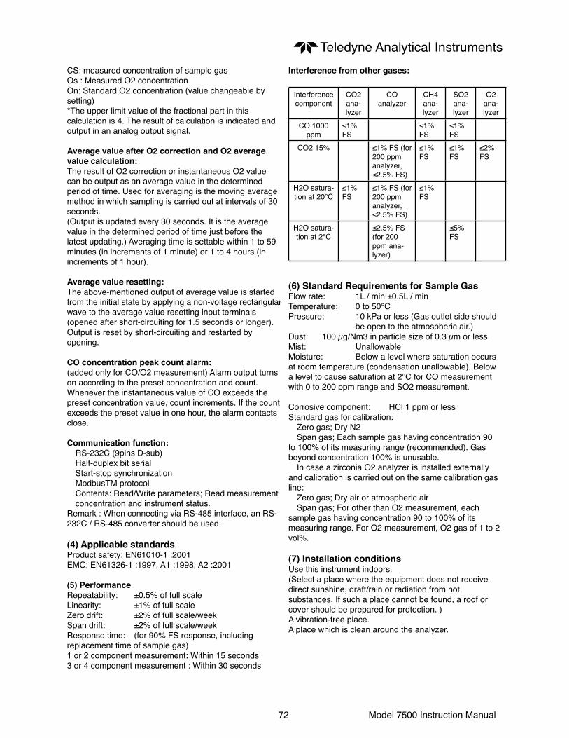
72 Model 7500 Instruction Manual
Teledyne Analytical InstrumentsCS: measured concentration of sample gasOs : Measured O2 concentrationOn: Standard O2 concentration (value changeable by setting)*The upper limit value of the fractional part in this calculation is 4. The result of calculation is indicated and output in an analog output signal.
Average value after O2 correction and O2 average value calculation:The result of O2 correction or instantaneous O2 value can be output as an average value in the determined period of time. Used for averaging is the moving average method in which sampling is carried out at intervals of 30 seconds. (Output is updated every 30 seconds. It is the average value in the determined period of time just before the latest updating.) Averaging time is settable within 1 to 59 minutes (in increments of 1 minute) or 1 to 4 hours (in increments of 1 hour).
Average value resetting:The above-mentioned output of average value is started from the initial state by applying a non-voltage rectangular wave to the average value resetting input terminals (opened after short-circuiting for 1.5 seconds or longer).Output is reset by short-circuiting and restarted by opening.
CO concentration peak count alarm:(added only for CO/O2 measurement) Alarm output turns on according to the preset concentration and count. Whenever the instantaneous value of CO exceeds the preset concentration value, count increments. If the count exceeds the preset value in one hour, the alarm contacts close.
Communication function: RS-232C (9pins D-sub) Half-duplex bit serial Start-stop synchronization ModbusTM protocol Contents: Read/Write parameters; Read measurement concentration and instrument status.Remark : When connecting via RS-485 interface, an RS-232C / RS-485 converter should be used.
(4) Applicable standardsProduct safety: EN61010-1 :2001EMC: EN61326-1 :1997, A1 :1998, A2 :2001
(5) PerformanceRepeatability: ±0.5% of full scaleLinearity: ±1% of full scaleZero drift: ±2% of full scale/weekSpan drift: ±2% of full scale/weekResponse time: (for 90% FS response, including replacement time of sample gas)1 or 2 component measurement: Within 15 seconds3 or 4 component measurement : Within 30 seconds
Interference from other gases:
Interference component
CO2ana-lyzer
COanalyzer
CH4ana-lyzer
SO2ana-lyzer
O2 ana-lyzer
CO 1000 ppm
≤1% FS
≤1% FS
≤1% FS
CO2 15% ≤1% FS (for 200 ppm analyzer, ≤2.5% FS)
≤1% FS
≤1% FS
≤2% FS
H2O satura-tion at 20°C
≤1% FS
≤1% FS (for 200 ppm analyzer, ≤2.5% FS)
≤1% FS
H2O satura-tion at 2°C
≤2.5% FS (for 200 ppm ana-lyzer)
≤5% FS
(6) Standard Requirements for Sample GasFlow rate: 1L / min ±0.5L / minTemperature: 0 to 50°CPressure: 10 kPa or less (Gas outlet side should be open to the atmospheric air.)Dust: 100 µg/Nm3 in particle size of 0.3 µm or lessMist: UnallowableMoisture: Below a level where saturation occurs at room temperature (condensation unallowable). Below a level to cause saturation at 2°C for CO measurement with 0 to 200 ppm range and SO2 measurement.
Corrosive component: HCl 1 ppm or lessStandard gas for calibration: Zero gas; Dry N2 Span gas; Each sample gas having concentration 90 to 100% of its measuring range (recommended). Gas beyond concentration 100% is unusable. In case a zirconia O2 analyzer is installed externally and calibration is carried out on the same calibration gas line: Zero gas; Dry air or atmospheric air Span gas; For other than O2 measurement, each sample gas having concentration 90 to 100% of its measuring range. For O2 measurement, O2 gas of 1 to 2 vol%.
(7) Installation conditionsUse this instrument indoors.(Select a place where the equipment does not receive direct sunshine, draft/rain or radiation from hot substances. If such a place cannot be found, a roof or cover should be prepared for protection. )A vibration-free place.A place which is clean around the analyzer.

73 Model 7500 Instruction Manual
Teledyne Analytical Instruments
9.2 Code symbols

74 Model 7500 Instruction Manual
Teledyne Analytical Instruments

75 Model 7500 Instruction Manual
Teledyne Analytical Instruments
<Code specification for ordering>(1) Code symbols should be specified.(2) Range combination should be the one allowed in separate tables.
(note 1) “Y” should be specified when only O2 measurement is necessary.
(note 2) External O2 sensor signal should be 0-1VDC linear of full scale, when “ B ” is specified at the 6th digit.
(note 3) “C” should be specified when “ Y ” is specified at the 5th digit.
(note 4) Allowable combinations of ranges are specified in the Table 1 to 6 in page 9-7 and 9-8.
(note 5) Allowed only for CO analyzer.
(note 6) Allowed only for CO and CO2 analyzers.
(note 7) O2 correction is carried out for CO and SO2. At the same time, average value output after O2 correction and O2 average value output are added. Peak count alarm is carried out for CO.
(note 8) “Y” should be specified when without O2 measurement (when 6th digit is Y).
(note 9) A gas composition table should be issued.
(note 10) Rated voltage of supplied power cable and plug configuration differ when “E” and “U” are specified at the 10th digit. Select one from three power voltages. Plug configuration is North America type when specifying “E”, and European type when specifying “U”.

76 Model 7500 Instruction Manual
Teledyne Analytical InstrumentsMeasurable component and range - availability check table -

77 Model 7500 Instruction Manual
Teledyne Analytical Instruments
Table 5: Triple component analyzer (CO2, CO, CH4)
Covered in combination of Table 2, Table 3 and Table 4.

78 Model 7500 Instruction Manual
Teledyne Analytical Instruments
9.3 Outline diagram
(1) Main unit

79 Model 7500 Instruction Manual
Teledyne Analytical Instruments(2) Accessory slide rail (unit: mm)
* The slide rails are attached to this equipment when designated.
Model : 305A-20/Accuride International Inc.
19-inch rack mounting method:The mass of the instrument should be supported at the bottom of the unit (or the side of the unit when mounted with the slide rails).
Also, for facilitate maintenance, a structure which allows extraction of the main unit by using the slide rail is recommended.

Teledyne Analytical Instruments
80 Model 7500 Instruction Manual
Appendix
Drawing List
D79104 Outline diagram