operating instructions for - teledyne … · ax300-i teledyne analytical instruments iv safety...
TRANSCRIPT
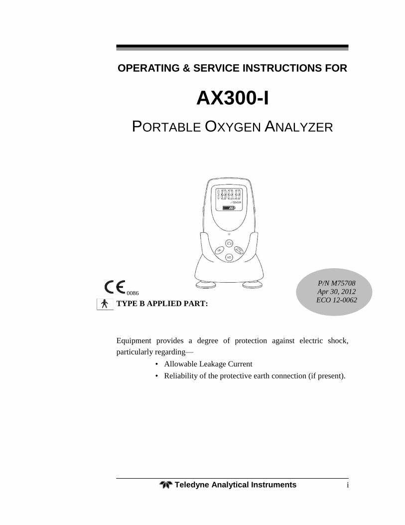
Portable Oxygen Analyzer
Teledyne Analytical Instruments i
OPERATING & SERVICE INSTRUCTIONS FOR
AX300-I
PORTABLE OXYGEN ANALYZER
0086
TYPE B APPLIED PART:
Equipment provides a degree of protection against electric shock,
particularly regarding—
• Allowable Leakage Current
• Reliability of the protective earth connection (if present).
P/N M75708
Apr 30, 2012
ECO 12-0062
AX300-I
Teledyne Analytical Instruments ii
Copyright © 2009 Teledyne Analytical Instruments.
All Rights Reserved
No part of this manual may be reproduced, transmitted, transcribed, stored in a retriev-
al system, or translated into any other language or computer language in whole or in
part, in any form or by any means, whether it be electronic, mechanical, optical, ma-
nual, or otherwise, without prior written consent of Teledyne Analytical Instruments,
16830 Chestnut Street, City of Industry, CA 91749-1580, USA.
Warranty
Teledyne warrants that the goods are free from defects of material and of construction
for a period of 2 years (or less, as the case may be, with consumables) from the date of
shipment from Teledyne. The liability of Teledyne, if any, shall be limited solely to the
replacement or repair of the goods, and shall not include shipping costs or other inci-
dental damages as defined in Section 2-715 of the U.S. Uniform Commercial Code.
Teledyne cannot warrant any damage resulting from unauthorized repair, misuse, im-
proper maintenance, negligence, or other events not caused by Teledyne or our goods.
CAUTION: FEDERAL LAW RESTRICTS THIS DEVICE TO SALE BY OR ON THE ORDER OF A PHYSICIAN.
Portable Oxygen Analyzer
Teledyne Analytical Instruments iii
About This Manual
This Manual describes the installation, configuration, operation and
maintenance instructions for Model AX300-I portable oxygen analyzer.
This Manual contains Cautions, Warnings, and Notes to ensure safe
and efficient performance of the analyzer.
For convenience with operating and maintaining your analyzer, this
manual includes Specifications, Troubleshooting and Maintenance Spare
Parts sections.
How To Use This Manual
This manual is designed to walk you through the initial set-up of
the AX300-I Portable Oxygen Analyzer. After you have used it to in-
itially commission your analyzer, it becomes a quick reference guide to
help you with specific questions or operating challenges.
Before operating the analyzer for the first time, you are advised to
read and familiarize yourself with the contents of this manual.
AX300-I
Teledyne Analytical Instruments iv
Safety Messages
Your safety and the safety of others are very important. Please care-
fully read and understand the Caution, Warning and Notes found in sev-
eral places in the manual.
CAUTION: THE ANALYZER SHOULD ONLY BE USED FOR THE PUR-POSES AND IN THE MANNER DESCRIBED IN THIS MA-NUAL.
IF YOU USE THE ANALYZER IN A MANNER OTHER THAN THAT FOR WHICH IT WAS INTENDED, UNPREDICTABLE BEHAVIOR COULD RESULT POSSIBLY ACCOMPANIED WITH HAZARDOUS CONSEQUENCES.
Portable Oxygen Analyzer
Teledyne Analytical Instruments v
Table of Contents
Safety Messages .......................................................................... iv
List of Figures .............................................................................. vii
List of Tables .............................................................................. viii
Introduction ................................................................................... 1
1.1 Features 2
1.2 Options 3
1.3 Applications 3
1.4 Operation Summary 3
Operating Instructions .................................................................. 5
2.1 Setup 5
2.1.1 Sensor Installation or Replacement 5
2.1.2 Mounting 7
2.1.2.1 V-Mount Adapter Installation 7
2.1.2.2 Universal Mounting Clamp Installation 8
2.1.3 Battery Installation 8
2.1.4 Calibration 9
2.1.5 Output 0-1 VDC or RS232 11
2.2 Operating Instructions 13
2.2.1 Procedure 13
2.3 Factors Affecting Sampling Accuracy 14
2.3.1 Humidity 14
2.3.2 Temperature 14
2.3.3 Pressure 15
2.3.4 Discrepancy in Readings 15
2.3.5 Anesthetic Gases 15
2.3.5.1 Gases That MAY INDUCE Reading Error 15
2.3.5.2 Care After Use in Nitrous Oxide 16
2.3.6 Cleaning 17
2.4 Dos and Don’ts 17
Service Instructions .................................................................... 19
AX300-I
Teledyne Analytical Instruments vi
3.1 General Service Information 19
3.2 Overall Maintenance 19
3.3 Battery Maintenance 19
3.4 Sensor Maintenance 19
3.5 Calibration 20
3.6 Factors Affecting Sampling Accuracy 20
3.7 Troubleshooting 20
3.8 Watchdog 23
3.9 Other Problems with the Analyzer 24
3.10 Return Authorization for Service 24
Appendix ...................................................................................... 25
A.1 Specifications 25
A.2 Spare Parts List 26
A.3 Optional Accessories 26
Portable Oxygen Analyzer
Teledyne Analytical Instruments vii
List of Figures
Figure 1-1: AX300-I Front View ....................................................... 1
Figure 2-1: Installing the R17MED Sensor ...................................... 6
Figure 2-2: Sensor Cable Connection to Analyzer ......................... 6
Figure 2-3: Mounting the Sensor in the Tee Adapter ....................... 7
Figure 2-4: V-Mount Adapter Installation ......................................... 7
Figure 2-5: Brass Insert for Universal Mounting Clamp ................... 8
Figure 2-6: Installing Batteries ......................................................... 9
Figure 2-7: Calibration Sequence .................................................. 10
Figure 2-8: 0-1 VDC or RS 232 Digital Output Port ....................... 12
AX300-I
Teledyne Analytical Instruments viii
List of Tables
Table 2-1: Oxygen Reading Error in a Mixture of Anesthetic Gas . 16
Table 3-1 Troubleshooting ............................................................ 20
Table 3.2 Error Codes ................................................................... 23
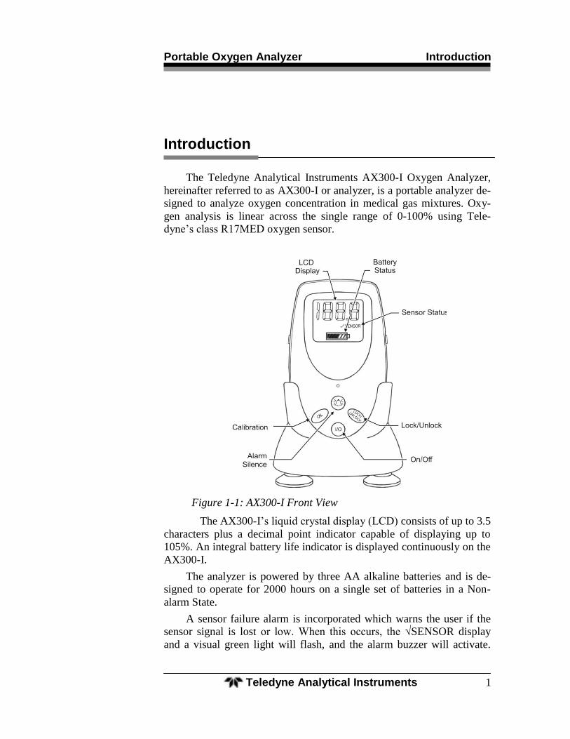
Portable Oxygen Analyzer Introduction
Teledyne Analytical Instruments 1
Introduction
The Teledyne Analytical Instruments AX300-I Oxygen Analyzer,
hereinafter referred to as AX300-I or analyzer, is a portable analyzer de-
signed to analyze oxygen concentration in medical gas mixtures. Oxy-
gen analysis is linear across the single range of 0-100% using Tele-
dyne’s class R17MED oxygen sensor.
Figure 1-1: AX300-I Front View
The AX300-I’s liquid crystal display (LCD) consists of up to 3.5
characters plus a decimal point indicator capable of displaying up to
105%. An integral battery life indicator is displayed continuously on the
AX300-I.
The analyzer is powered by three AA alkaline batteries and is de-
signed to operate for 2000 hours on a single set of batteries in a Non-
alarm State.
A sensor failure alarm is incorporated which warns the user if the
sensor signal is lost or low. When this occurs, the √SENSOR display
and a visual green light will flash, and the alarm buzzer will activate.
Introduction AX300-I
Teledyne Analytical Instruments 2
This alarm condition is also triggered when the oxygen concentration at
the point of analysis falls below 18% (Reference: ISO 7767 standard).
For safety reasons, the audible alarm cannot be silenced until the alarm
condition is resolved.
CAUTION: DURING NORMAL USE, ALARM CONDITIONS SHOULD NOT BE OVERRIDDEN BY ACTIONS SUCH AS HOLDING THE ALARM SILENCE KEY DEPRESSED OR REMOVING THE BATTERIES. THE CAUSE FOR THE ALARM CONDI-TION SHOULD FIRST BE RESOLVED.
CAUTION: WHILE HOLDING DOWN THE ALARM SILENCE KEY MAY MOMENTARILY SILENCE THE ALARM BUZZER, AUDIBLE ALARM WILL RETURN UPON DISENGAGING THE ALARM SILENCE KEY. HOLDING THE KEY FOR LONGER DURA-TIONS WILL INITIATE THE “STUCK KEY” ALARM, WHICH CAN BE DEACTIVATED ONLY VIA REMOVING THE BAT-TERIES FROM THE ANALYZER. ANALYZER SHOULD BE RECALIBRATED UP ON REPOWERING THE ANALYZER.
NOTE: THE ALARM SILENCE KEY DOES NOT PLAY ANY ROLE IN THIS VERSION OF THE ANALYZER. IT IS DESIGNED IN FOR ANY POSSIBLE FUTURE PRODUCT MODIFICATION.
1.1 Features
The following features are standard on the AX300-I:
Large easy to read 3½-digit LCD (see options)
Automatic LCD back lighting upon key press
Microprocessor controlled
Sensor fail/disconnect alarm indicator (audible and visual)
Non-adjustable concentration alarm below 18% O2
2000 operating hours from 3 AA alkaline batteries
Battery status indicator
Stand for upright tabletop deployment
Optional hardware for pole clamping and V block support
Rugged high impact ABS plastic construction
Splash resistant case.
Long life class R17MED sensor
0-1 VDC digital output (optional RS-232)
CE marking per EU MDD and CSA approved
Portable Oxygen Analyzer Introduction
Teledyne Analytical Instruments 3
1.2 Options
The following options are available for the AX 300-I analyzer:
A-Option—2½-digit LCD instead of 3½-digit
Note: Contact the factory for modifying your analyzer for 2½-digit LCD. For RS-232 reconfiguration, see Section 2.1.5.
B-Option—RS 232 digital output instead of 0-1VDC
Universal Pole Mounting Clamp (P/N CP 2345)
V-Mount Pole Clamp (P/N CP 2344)
V-Mount Wall Adapter P/N B 647)
0-1 VDC Interface Cable (P/NB-75554)
RS 232 Interface Cable (P/N B-75555)
1.3 Applications
The AX300-I analyzer is intended for spot checking the concentra-
tion of oxygen in gas mixtures used in applications such as Anesthesia
gas delivery and Respiratory care, and is intended for adult, pediatric
and neonatal populations.
1.4 Operation Summary
The AX300-I analyzer uses Teledyne Analytical Instruments’ Pa-
tented R17MED oxygen sensor. The sensor output is used to determine
the oxygen gas concentration that is displayed on the LCD screen. The
concentration alarm of AX300-I analyzer is non-defeatable and will
alarm when the oxygen concentration falls below the threshold of 18%.
This alarm is tied to sensor fail/disconnect alarm that will also warn the
user of a possible sensor problem when the oxygen concentration is less
than 18%. When a fault is detected, the SENSOR indicator is displayed
on the LCD, and the audible and visual alarms are activated.
The Class R17MED oxygen sensor is a disposable sensor. The sen-
sor has a cathode (sensing electrode), an anode (counter electrode), and
a compatible electrolyte, and is packaged in a small plastic sensor body.
Oxygen entering the sensor reacts with the anode and a proportional cur-
rent is collected at the cathode, which is then converted into a digital
signal and displayed on the LCD screen on the analyzer.
Used with the R17MED sensor is a removable plastic diverter. This
diverter is used to facilitate the transport of gas mixtures through the
sensor. The diverter, packaged separately when shipped, is necessary
when the tee adapter is used to sample gas flowing through a tube.
Introduction AX300-I
Teledyne Analytical Instruments 4
The diverter is not necessary, and should not be used, when the
sensor is placed directly in a chamber or when the sensor is used in con-
fined volume analysis such as incubators and inhalation tents.
CAUTION STATEMENTS:
THE R17MED SENSOR CONTAINS A CAUSTIC ELECTRO-LYTE AND LEAD. DO NOT TRY TO OPEN THE SENSOR ASSEMBLY. CHECK THE SENSOR PERIODICALLY FOR LEAKS. IF THE SENSOR IS LEAKING, REPLACE IT. DO NOT TRY TO REPAIR IT. CONTACT YOUR DISTRIBUTOR OR TELEDYNE FOR THE MATERIAL SAFETY DATA SHEET RELATED TO HANDLING AND DISPOSAL OF THE SEN-SOR.
THE R17MED SENSOR CONTAINS A CAUSTIC ELECTRO-LYTE, AND IN THE EVENT OF A LEAK, THE ELECTROLYTE MAY ATTACK CERTAIN MATERIALS IT IS EXPOSED TO, SUCH AS ALUMINUM. USE PRECAUTION IN YOUR CHOICE OF INTERFACE MATERIALS.
REMOVE AND SAVE THE DIVERTER WHEN THE SENSOR IS USED IN CONFINED VOLUME APPLICATIONS.
THE AX300-I OXYGEN ANALYZER, R17MED OXYGEN SENSOR AND ASSOCIATED HARDWARE ARE INTENDED FOR USE AS SECONDARY DEVICES TO VERIFY THE CONCENTRATION OF OXYGEN IN GAS MIXTURES. DO NOT USE THESE DEVICES AS PRIMARY LIFE-SUPPORT OR PRIMARY MONITORING DEVICES.
THE INFORMATION OBTAINED FROM THE AX300-I SHOULD NEVER BE USED TO ADJUST A LIFE-SUPPORT SYSTEM. IT SHOULD ONLY BE USED AS AN INDICATION THAT THE LIFE SUPPORT SYSTEM OR DEVICE IN THE BREATHING SYSTEM THAT AX300-I IS BEING USED WITH MAY REQUIRE SERVICE AND/OR CALIBRATION.
Portable Oxygen Analyzer Operating Instructions
Teledyne Analytical Instruments 5
Operating Instructions
Notes:
Upon receipt, INSPECT THE ENTIRE UNIT FOR ANY DAMAGE. Check the unit and all included accessories for broken or loose parts. If damaged, DO NOT USE. Notify the shipper, your distributor or Teledyne Analytical Instruments.
This equipment is internally powered using 3 AA batteries.
The LOCK/UNLOCK key helps prevent accidental change to the calibration set point. At least two keys must be pressed in order to modify the critical calibra-tion set point value.
If the keys are unlocked and no keys are pressed, the analyzer will revert to the locked mode within nine seconds.
2.1 Setup
To use your AX300-I analyzer, first install the batteries, then install the
oxygen sensor and then, calibrate the analyzer using the steps outlined in section
2.1.4.
2.1.1 Sensor Installation or Replacement
Note: Install the R17MED oxygen sensor before using the AX300-I oxygen analyzer.
1. Remove the new sensor from its protective bag. Inspect the sensor for
damage or electrolyte leakage.
Warning: The sensor has a caustic electrolyte. Do not use a damaged or leaking sensor. Do not let the electrolyte come in contact with the skin. If it does, flush affected area with water. Do not attempt to open or repair the sensor.
Warning: The sensor also contains lead. Leaking or exhausted sensors should be handled and disposed of in accordance with local regulations.
Warning: The AX300 oxygen analyzer, R17MED oxygen sensor, and associated hardware are non-sterile devices. Autoclaving or other chemical clean-ing may damage the analyzer and the sensor.
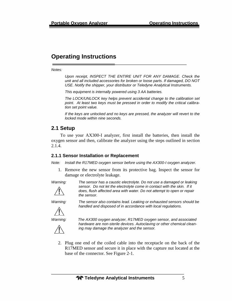
2. Plug one end of the coiled cable into the receptacle on the back of the
R17MED sensor and secure it in place with the capture nut located at the
base of the connector. See Figure 2-1.
Operating Instructions AX300-I
Teledyne Analytical Instruments 6
Figure 2-1: Installing the R17MED Sensor
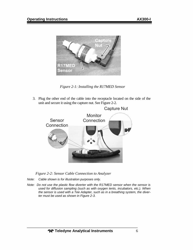
3. Plug the other end of the cable into the receptacle located on the side of the
unit and secure it using the capture nut. See Figure 2-2.
Figure 2-2: Sensor Cable Connection to Analyzer
Note: Cable shown is for illustration purposes only.
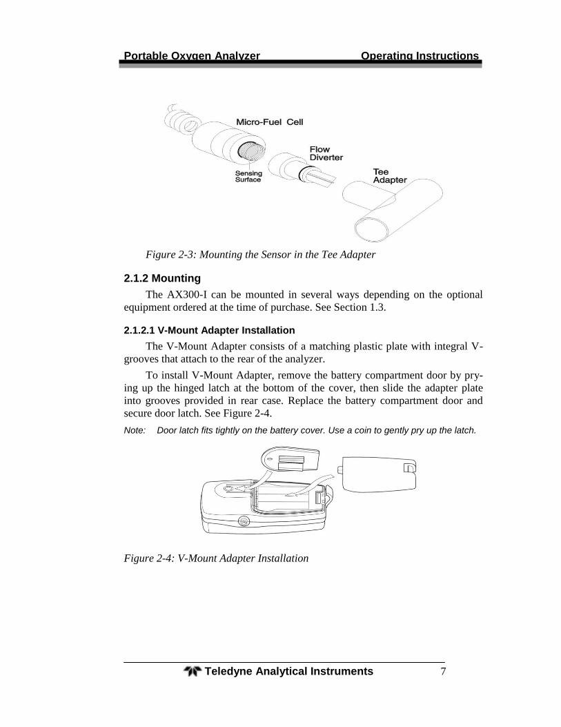
Note: Do not use the plastic flow diverter with the R17MED sensor when the sensor is used for diffusion sampling (such as with oxygen tents, incubators, etc.). When the sensor is used with a Tee Adapter, such as in a breathing system, the diver-ter must be used as shown in Figure 2-3.
Portable Oxygen Analyzer Operating Instructions
Teledyne Analytical Instruments 7
Figure 2-3: Mounting the Sensor in the Tee Adapter
2.1.2 Mounting
The AX300-I can be mounted in several ways depending on the optional
equipment ordered at the time of purchase. See Section 1.3.
2.1.2.1 V-Mount Adapter Installation
The V-Mount Adapter consists of a matching plastic plate with integral V-
grooves that attach to the rear of the analyzer.
To install V-Mount Adapter, remove the battery compartment door by pry-
ing up the hinged latch at the bottom of the cover, then slide the adapter plate
into grooves provided in rear case. Replace the battery compartment door and
secure door latch. See Figure 2-4.
Note: Door latch fits tightly on the battery cover. Use a coin to gently pry up the latch.
Figure 2-4: V-Mount Adapter Installation
Operating Instructions AX300-I
Teledyne Analytical Instruments 8
2.1.2.2 Universal Mounting Clamp Installation
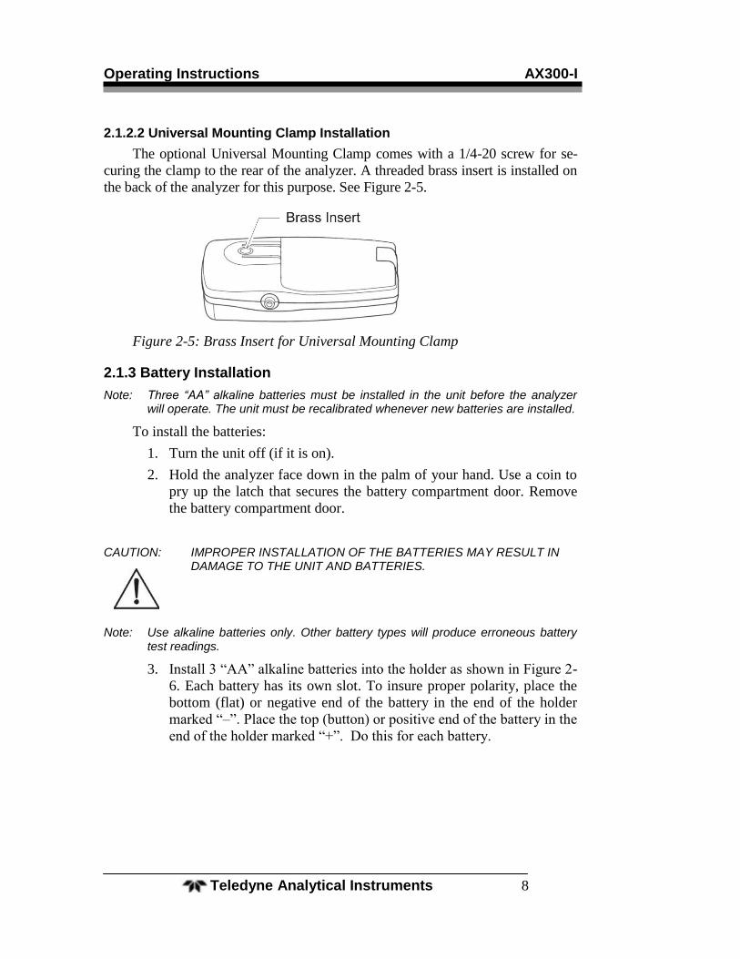
The optional Universal Mounting Clamp comes with a 1/4-20 screw for se-
curing the clamp to the rear of the analyzer. A threaded brass insert is installed on
the back of the analyzer for this purpose. See Figure 2-5.
Figure 2-5: Brass Insert for Universal Mounting Clamp
2.1.3 Battery Installation
Note: Three “AA” alkaline batteries must be installed in the unit before the analyzer will operate. The unit must be recalibrated whenever new batteries are installed.
To install the batteries:
1. Turn the unit off (if it is on).
2. Hold the analyzer face down in the palm of your hand. Use a coin to
pry up the latch that secures the battery compartment door. Remove
the battery compartment door.
CAUTION: IMPROPER INSTALLATION OF THE BATTERIES MAY RESULT IN DAMAGE TO THE UNIT AND BATTERIES.
Note: Use alkaline batteries only. Other battery types will produce erroneous battery test readings.
3. Install 3 ―AA‖ alkaline batteries into the holder as shown in Figure 2-
6. Each battery has its own slot. To insure proper polarity, place the
bottom (flat) or negative end of the battery in the end of the holder
marked ―–‖. Place the top (button) or positive end of the battery in the
end of the holder marked ―+‖. Do this for each battery.
Portable Oxygen Analyzer Operating Instructions
Teledyne Analytical Instruments 9
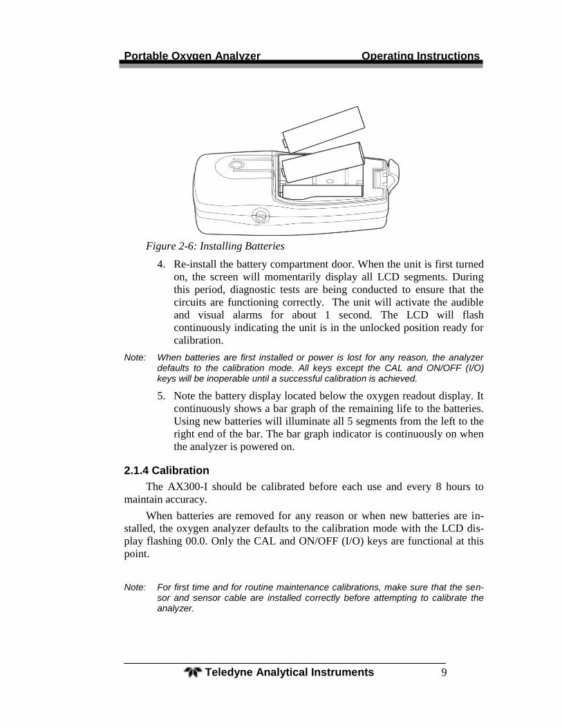
Figure 2-6: Installing Batteries
4. Re-install the battery compartment door. When the unit is first turned
on, the screen will momentarily display all LCD segments. During
this period, diagnostic tests are being conducted to ensure that the
circuits are functioning correctly. The unit will activate the audible
and visual alarms for about 1 second. The LCD will flash
continuously indicating the unit is in the unlocked position ready for
calibration.
Note: When batteries are first installed or power is lost for any reason, the analyzer defaults to the calibration mode. All keys except the CAL and ON/OFF (I/O) keys will be inoperable until a successful calibration is achieved.
5. Note the battery display located below the oxygen readout display. It
continuously shows a bar graph of the remaining life to the batteries.
Using new batteries will illuminate all 5 segments from the left to the
right end of the bar. The bar graph indicator is continuously on when
the analyzer is powered on.
2.1.4 Calibration
The AX300-I should be calibrated before each use and every 8 hours to
maintain accuracy.
When batteries are removed for any reason or when new batteries are in-
stalled, the oxygen analyzer defaults to the calibration mode with the LCD dis-
play flashing 00.0. Only the CAL and ON/OFF (I/O) keys are functional at this
point.
Note: For first time and for routine maintenance calibrations, make sure that the sen-sor and sensor cable are installed correctly before attempting to calibrate the analyzer.
Operating Instructions AX300-I
Teledyne Analytical Instruments 10
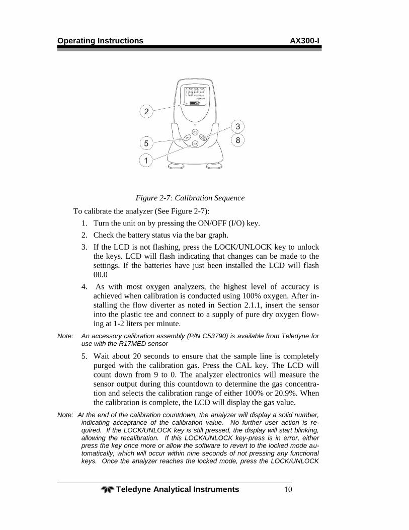
Figure 2-7: Calibration Sequence
To calibrate the analyzer (See Figure 2-7):
1. Turn the unit on by pressing the ON/OFF (I/O) key.
2. Check the battery status via the bar graph.
3. If the LCD is not flashing, press the LOCK/UNLOCK key to unlock
the keys. LCD will flash indicating that changes can be made to the
settings. If the batteries have just been installed the LCD will flash
00.0
4. As with most oxygen analyzers, the highest level of accuracy is
achieved when calibration is conducted using 100% oxygen. After in-
stalling the flow diverter as noted in Section 2.1.1, insert the sensor
into the plastic tee and connect to a supply of pure dry oxygen flow-
ing at 1-2 liters per minute.
Note: An accessory calibration assembly (P/N C53790) is available from Teledyne for use with the R17MED sensor
5. Wait about 20 seconds to ensure that the sample line is completely
purged with the calibration gas. Press the CAL key. The LCD will
count down from 9 to 0. The analyzer electronics will measure the
sensor output during this countdown to determine the gas concentra-
tion and selects the calibration range of either 100% or 20.9%. When
the calibration is complete, the LCD will display the gas value.
Note: At the end of the calibration countdown, the analyzer will display a solid number, indicating acceptance of the calibration value. No further user action is re-quired. If the LOCK/UNLOCK key is still pressed, the display will start blinking, allowing the recalibration. If this LOCK/UNLOCK key-press is in error, either press the key once more or allow the software to revert to the locked mode au-tomatically, which will occur within nine seconds of not pressing any functional keys. Once the analyzer reaches the locked mode, press the LOCK/UNLOCK
Portable Oxygen Analyzer Operating Instructions
Teledyne Analytical Instruments 11
key and press the CAL key to repeat calibration.
Note: The AX300-I can only be calibrated using certified medical grade 100% oxygen or ambient level air (20.9% Oxygen). Improper calibration or use of other gas con-
centrations will either activate the SENSOR indicator or render the analyzer to assume that the gas delivered for calibration was 100% Oxygen. This latter be-havior of the analyzer, which is common across other peer group analyzers, would introduce significant error in analysis. Hence, use only certified medical grade 100% Oxygen gas or ambient level air (20.9% Oxygen) to calibrate your analyzer.
6. Remove the sensor from the oxygen supply and confirm the LCD
reads less than 22% in room air. It is not necessary for it to read ex-
actly 20.9%.
7. It is important to perform the calibration carefully and thoroughly, us-
ing calibration gases that are free from contaminates. The accuracy of
the analyzer is only as good as the accuracy of calibration gases used
and the accuracy of the procedure used to calibrate the analyzer.
Note: A single point air calibration is not recommended unless the sensor can be ex-posed to a known source of fresh outdoor air. Hospital room air may often have oxygen at above normal ambient levels of 20.9%, which will introduce errors in the calibration. Air calibration should only be used for analyzing oxygen levels between 21% and 40% and should never be used where a high degree of accu-racy is needed.
Note: Never calibrate the unit in humidified gas, as water vapor makes the oxygen concentration appear lower than it really is. See Section 2.3.1: Humidity.
8. The analyzer is now ready for use.
2.1.5 Output 0-1 VDC or RS232
The AX300-I Portable Oxygen Analyzer comes with optional 0-1 VDC and
RS232 signal outputs for use with compatible external recording, indicating or
computing equipment.
An optional 0-1 VDC Interface Cable (P/N B-75554) is available from Te-
ledyne for accessing the voltage output.
To connect the analyzer to an analog recording/indicating device:
1. Insert one end of the interface cable into the output port on the side of
the analyzer. See Figure 2-8.
2. Insert the other end into the analog recorder/indicator device
equipped to handle a 0-1 VDC signal.
When properly calibrated, the output signal generated by the analyzer is li-
near and proportional to the oxygen concentration.
If you requested Option-B (RS 232 digital output) at the time of purchase, a
digital RS 232 signal is output from the output port shown in Figure 2-8. Use the
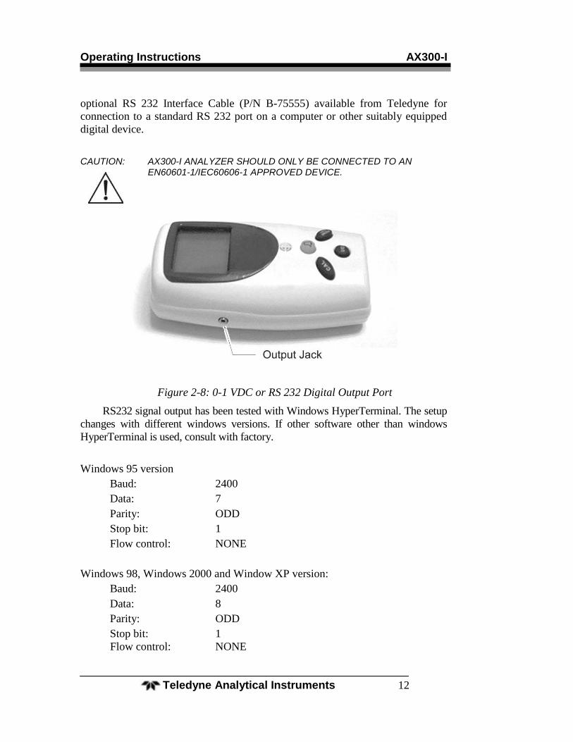
Operating Instructions AX300-I
Teledyne Analytical Instruments 12
optional RS 232 Interface Cable (P/N B-75555) available from Teledyne for
connection to a standard RS 232 port on a computer or other suitably equipped
digital device.
CAUTION: AX300-I ANALYZER SHOULD ONLY BE CONNECTED TO AN EN60601-1/IEC60606-1 APPROVED DEVICE.
Figure 2-8: 0-1 VDC or RS 232 Digital Output Port
RS232 signal output has been tested with Windows HyperTerminal. The setup
changes with different windows versions. If other software other than windows
HyperTerminal is used, consult with factory.
Windows 95 version
Baud: 2400
Data: 7
Parity: ODD
Stop bit: 1
Flow control: NONE
Windows 98, Windows 2000 and Window XP version:
Baud: 2400
Data: 8
Parity: ODD
Stop bit: 1
Flow control: NONE
Portable Oxygen Analyzer Operating Instructions
Teledyne Analytical Instruments 13
2.2 Operating Instructions
2.2.1 Procedure
Note: Prior to every use, always test the batteries, check the sensor for any leaks or damage, and check the analyzer calibration.
The AX300-I analyzer can be used to measure a gas mixture for oxygen in
two basic modes:
In the inhalation side of breathing system upstream of any antibac-
terial filters, humidifiers and other such medicating devices.
In confined volumes such as in incubators or tents.
When analyzing for oxygen in breathing systems, the flow diverter must be
used. The diverter should be screwed onto the threaded front end of the
R17MED sensor. A tee adapter (plastic, P/N A268, or metal, P/N A283) should
be placed into the breathing loop, and the above sensor assembly plugged into
the tee adapter. See Figure 2-3.
CAUTION: CHECK THE BREATHING SYSTEM FOR LEAKS. BE CERTAIN THAT THE SYSTEM DOWNSTREAM OF THE SENSOR DOES NOT PRO-DUCE ANY BACKPRESSURE OR RESTRICTION TO FLOW. ER-RORS IN READINGS WILL RESULT IF THIS IS NOT FOLLOWED.
THE OXYGEN SENSOR IS A NON-STERILE DEVICE AND SHOULD BE USED IN CONJUCTION WITH AN ANTI-BACTERIAL FILTER. AL-WAYS INSTALL THE SENSOR ON THE INSPIRED LINE AHEAD OF FILTERS, HUMIDIFIERS AND MEDICATING DEVICES. NEVER IN-STALL THE SENSOR IN A LOCATION THAT WILL EXPOSE THE SENSOR TO PATIENTS’ EXHALED BREATH OR SECRETIONS UN-LESS YOU INTEND TO DISPOSE OF THE SENSOR AND FLOW ADAPTER AFTER USE.
Operating Instructions AX300-I
Teledyne Analytical Instruments 14
When analyzing for oxygen in confined volumes such as incubators, hoods,
etc., the flow diverter must be removed from the R17MED sensor so that it does
not interfere with the rapid exchange of gases to and from the sensing surface of
the sensor. Failure to remove the diverter in these applications may adversely
affect the response time of the sensor.
The R17MED sensor can be placed or hung inside incubators, tents, etc.
When it is necessary to thread the cable through a small hole in order to gain
access to the inside of a chamber, the cable should be disconnected at the sensor,
threaded through the hole, and reconnected inside the chamber.
2.3 Factors Affecting Sampling Accuracy
2.3.1 Humidity
Humidity does not directly affect the accuracy of the sensor's measurement.
However, when a nebulizer or other device is used to increase moisture levels in
gas mixtures, the moisture actually dilutes the mixture. This dilution effect de-
creases the oxygen concentration. Your portable oxygen analyzer accurately
measures the decreased oxygen concentration.
As with all diffusion based oxygen sensors, excessive condensation on the
sensing surface of the R17MED will block the diffusion of oxygen to the sensor,
rendering it inoperative. We recommend installing the sensor on the dry side of
the breathing system at all times.
2.3.2 Temperature
The R17MED oxygen sensor compensates for ambient temperature changes
in the range of 0–40°C (32–104°F). Since the thermistor that compensates for
these changes is located in the rear of the sensor assembly, it is important that
gas mixtures, flowing over the front of the sensor, be at room temperature, which
is assumed to the temperature around the rear of the sensor. Reading errors may
occur if gases at higher temperature from devices such as heated humidifier are
used to measure oxygen with R17MED oxygen sensor.
A small thermal tracking error may be encountered in applications where
the entire sensor assembly is placed in the gas mixture to be analyzed (such as in
the incubators). Holding the sensor in your hand for more than a few minutes can
also affect the temperature tracking which appears as a slow drift on the LCD.
No adjustments should be made during this period since this error will be elimi-
nated when both the thermistor and sensing electrode have had sufficient time to
come to thermal equilibrium. This can take up to 2 hours.
Portable Oxygen Analyzer Operating Instructions
Teledyne Analytical Instruments 15
2.3.3 Pressure
Virtually all gas sensors and analyzers measure the partial pressure of the
gas that they sample. The only time that these analyzers can accurately read per-
centages is when the total pressure does not vary over time between calibrations
and use. For this reason it is important to calibrate the AX300-I oxygen analyzer
(with R17MED oxygen sensor) at regular intervals. It is recommended that the
unit be calibrated prior to each use or every 8 hours. It is recommended that the
analyzer be calibrated at the same pressure as the gas it will be used to analyze.
If the gas being analyzed flows through some length of tubing, use similar tub-
ing/apparatus and same pressure/flow rates when calibrating the analyzer.
When a ventilator is a part of the breathing system, the alternating ―breath-
ing‖ pressure cycles generated by the ventilator will be sensed as pressure pulses
by the sensor, and over time, such pulses manifest as pressure increases in the
fast-reacting sensors such as R17MED. This perceived pressure increase results
in correspondingly higher oxygen reading. While the concentration of oxygen is
not changing, it is the total pressure that is increasing producing a corresponding
increase in the partial pressure of oxygen.
2.3.4 Discrepancy in Readings
When a discrepancy in oxygen readings is detected, the oxygen analyzer’s
readings should be verified by checking the AX300-I battery condition and cali-
bration using 100% oxygen. If the analyzer can be calibrated, the unit can be as-
sumed to be in good working order. If, after reinstalling the unit, the discrepancy
in oxygen readings persists, the problem is most likely elsewhere in the breathing
system. Resolve the cause(s) for the discrepancy before using the analyzer. The
troubleshooting section of this manual may provide additional assistance in lo-
cating the problem.
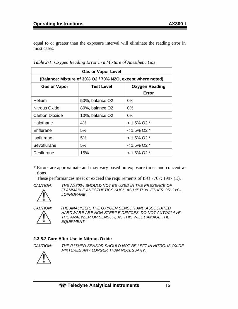
2.3.5 Anesthetic Gases
2.3.5.1 Gases That MAY INDUCE Reading Error
When using the R17MED sensor in the presence of anesthetic gases, the
oxygen reading may fall (see Table below). The magnitude of this error will de-
pend upon the level of oxygen and the duration of exposure.
The anesthetic agents listed in the following table (Halothane, Enflurane,
Isoflurane, Sevoflurane, and Desflurane) were vaporized into a stream of 30%
oxygen / 70% nitrous oxide, and the resulting drops in oxygen level after an ex-
posure of approximately two hours were noted.
Exposures in excess of two hours may produce slightly greater errors. The er-
rors listed are typical for all oxygen sensors such as the R17MED. Exposing the
sensor to air or gases that do not contain anesthetic agents for a period of time
Operating Instructions AX300-I
Teledyne Analytical Instruments 16
equal to or greater than the exposure interval will eliminate the reading error in
most cases.
Table 2-1: Oxygen Reading Error in a Mixture of Anesthetic Gas
Gas or Vapor Level
(Balance: Mixture of 30% O2 / 70% N2O, except where noted)
Gas or Vapor Test Level Oxygen Reading
Error
Helium 50%, balance O2 0%
Nitrous Oxide 80%, balance O2 0%
Carbon Dioxide 10%, balance O2 0%
Halothane 4% < 1.5% O2 *
Enflurane 5% < 1.5% O2 *
Isoflurane 5% < 1.5% O2 *
Sevoflurane 5% < 1.5% O2 *
Desflurane 15% < 1.5% O2 *
* Errors are approximate and may vary based on exposure times and concentra-
tions.
These performances meet or exceed the requirements of ISO 7767: 1997 (E).
CAUTION: THE AX300-I SHOULD NOT BE USED IN THE PRESENCE OF FLAMMABLE ANESTHETICS SUCH AS DIETHYL ETHER OR CYC-LOPROPANE.
CAUTION: THE ANALYZER, THE OXYGEN SENSOR AND ASSOCIATED HARDWARE ARE NON-STERILE DEVICES. DO NOT AUTOCLAVE THE ANALYZER OR SENSOR, AS THIS WILL DAMAGE THE EQUIPMENT.
2.3.5.2 Care After Use in Nitrous Oxide
CAUTION: THE R17MED SENSOR SHOULD NOT BE LEFT IN NITROUS OXIDE MIXTURES ANY LONGER THAN NECESSARY.
Portable Oxygen Analyzer Operating Instructions
Teledyne Analytical Instruments 17
After exposure to nitrous oxide mixtures, the sensor should be left in 100%
oxygen overnight (e.g., left in a breathing system that has been flushed with pure
oxygen). If this is not practical, when using the tee, remove the plastic flow di-
verter and leave the sensor in room air. If the oxygen reading continues to drop
after each use in nitrous oxide, the sensor should be removed from service. If the
sensor can no longer be calibrated or if there is any sign of electrolyte leakage,
the sensor should be disposed of in accordance with local regulations and the
Material Safety Data Sheet (MSDS) available through Teledyne.
2.3.6 Cleaning
The AX300-I and R17MED sensor are non-sterile devices.
The oxygen analyzer, oxygen sensor, and sensor interconnection cable may
be cleaned by wiping the surfaces with isopropyl alcohol or a mild cleaning solu-
tion.
When cleaning, do not allow liquids or moisture to enter the analyzer or
sensor internal cavities. Do not expose the electrical connections to the cleaning
solution. Do not immerse the analyzer, oxygen sensor or sensor interconnection
cable in water or any other liquid.
Do not expose the analyzer, oxygen sensor and interconnection cable to
steam, ethylene oxide, or radiation sterilization.
After cleaning, ensure that all surfaces are dry and the analyzer is properly
calibrated before using the analyzer.
2.4 Dos and Don’ts
– DO –
Read and understand the manual before using the analyzer
Calibrate every 8 hours or before every use.
Visually inspect the sensor for leakage before each use.
Calibrate using 100% oxygen and check in air.
Test batteries regularly and replace when battery indicator shows low
battery (no bars)
Keep the analyzer, sensor and connections dry, or on the dry side of
the breathing system.
Recalibrate after replacing the batteries.
Recalibrate after replacing the sensor.
Use only alkaline batteries.
Ensure that the R17MED sensor is properly connected to the analyz-
er.
Operating Instructions AX300-I
Teledyne Analytical Instruments 18
Always use the plastic flow diverter when using the tee adapter.
Remove and save the plastic flow diverter when using the sensor in
non-flowing applications
Use only isopropyl alcohol or mild detergent, if cleaning is required,
– DON’T –
Use this analyzer if you suspect any malfunction.
Use the analyzer in the presence of flammable gases.
Use anything but alkaline batteries.
Autoclave or freeze the sensor or analyzer.
Open or try to repair a leaking or broken sensor.
Immerse the unit or sensor in any liquid.
Pass hot or cold gas mixtures over the sensor.
Expose the unit to devices that produce high levels of radio, short
wave, microwave, x-ray, or high frequency interference.
Use cleaning agents or liquids in the cable receptacles or around the
battery compartment.
Place the unit in a water vapor-saturated environment.
Expose the LCD to excessive sunlight.
Expose the unit to a condensing water environment such as a mist
tent.
Portable Oxygen Analyzer Service Instructions
Teledyne Analytical Instruments 19
Service Instructions
3.1 General Service Information
Without access to special probes and test equipment, troubleshooting and repair
of the board or its components are not feasible. A factory replacement of the entire
PC board is recommended if necessary.
With the exception of replacing the sensor or batteries, there are no user-
serviceable components inside the unit. If a problem arises that cannot be corrected
by recalibration, changing the batteries or replacing the sensor as described in this
manual, the unit must be sent back to the factory for repair or replacement. See Sec-
tion 3.10 for instructions on obtaining a Return Merchandise Authorization (RMA)
number before sending a unit back to Teledyne for repair.
3.2 Overall Maintenance
The AX300-I analyzer requires very little maintenance, other than calibra-
tion, checking the batteries and sensor. Occasional cleaning of the plastic surface
can be done with isopropyl alcohol. There are no user-serviceable components
within the analyzer.
3.3 Battery Maintenance
DO: Test batteries regularly. (Replace immediately when all battery
strength indicator bars are missing).
DO: Always use alkaline batteries.
DO: Recalibrate after replacing batteries.
The AX300-I analyzer has a battery strength indicator that continuously
displays the approximate amount of useful life remaining on the set of installed
batteries. Excessive alarm activation will drain the batteries faster. The minimum
detectable change in battery voltage corresponds to an increment of about 50
hours, meaning that the battery voltage reading may not change for several hours
at a time.
If the analyzer is not used for a period of 30 days or more, the batteries
should be removed from the analyzer.
3.4 Sensor Maintenance
DO check the sensor for damage or leaks before use.
DON’T immerse the R17MED sensor in liquid.
DON’T autoclave the R17MED sensor.
Service Instructions AX300-I
Teledyne Analytical Instruments 20
DON’T open or try to repair the sensor.
Before every use, the sensor, cable and connections should be checked.
Check the sensor for leaks and condensation. Check the cable for splitting or
cracked insulation. Make sure the connections are tight and dry.
In the event that the sensor has been damaged, consult the Material Safety
Data Sheet in the Appendix for handling guidelines.
3.5 Calibration
Incorrect readings can often be traced to improper calibration. The AX300-I
should be calibrated before each use and every 8 hours to maintain accuracy. It
must be calibrated whenever new sensor or batteries are installed. Calibration
using methods other than described in section 2.1.4 will lead to improper opera-
tion.
Whenever new batteries are installed or removed for any reason, the oxygen
analyzer defaults to the calibration mode with the LCD display flashing 00.0.
Only the CAL and ON/OFF (I/O) keys are functional at this point.
3.6 Factors Affecting Sampling Accuracy
Refer to Section 2.3 of this manual.
3.7 Troubleshooting
The AX300-I oxygen analyzer provides a variety of built-in safety features that
prevent its use when a fault is detected. When a unit displays the message √ SENSOR
and sounds the audible and visual alarm continuously, it is an indication of a faulty
connection between the sensor and the unit or an expired or faulty sensor. It also indi-
cates when oxygen concentrations are below 18%.
For assistance with troubleshooting, see Table 3-1.
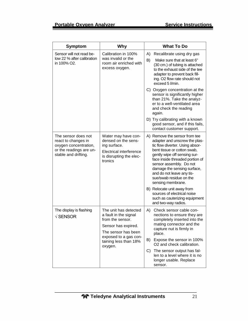
Table 3-1 Troubleshooting
Symptom Why What To Do
New sensor responds slow or drifts.
If the sensor is new and was just removed from its sealed bag it may need to run for several hours.
A) Wait 1–2 hours and recali-brate.
Portable Oxygen Analyzer Service Instructions
Teledyne Analytical Instruments 21
Symptom Why What To Do
Sensor will not read be-low 22 % after calibration in 100% O2.
Calibration in 100% was invalid or the room air enriched with excess oxygen.
A) Recalibrate using dry gas
B) Make sure that at least 6" (30 cm.) of tubing is attached to the exhaust side of the tee adapter to prevent back fill-ing. O2 flow rate should not exceed 5 l/min.
C) Oxygen concentration at the sensor is significantly higher than 21%. Take the analyz-er to a well-ventilated area and check the reading again.
D) Try calibrating with a known good sensor, and if this fails, contact customer support.
The sensor does not react to changes in oxygen concentration, or the readings are un-stable and drifting.
Water may have con-densed on the sens-ing surface.
Electrical interference is disrupting the elec-tronics
A) Remove the sensor from tee adapter and unscrew the plas-tic flow diverter. Using absor-bent tissue or cotton swab, gently wipe off sensing sur-face inside threaded portion of sensor assembly. Do not damage the sensing surface, and do not leave any tis-sue/swab residue on the sensing membrane.
B) Relocate unit away from sources of electrical noise such as cauterizing equipment and two-way radios.
The display is flashing
√ SENSOR
The unit has detected a fault in the signal from the sensor.
Sensor has expired.
The sensor has been exposed to a gas con-taining less than 18% oxygen.
A) Check sensor cable con-nections to ensure they are completely inserted into the mating connector and the capture nut is firmly in place.
B) Expose the sensor in 100% O2 and check calibration.
C) The sensor output has fal-len to a level where it is no longer usable. Replace sensor.
Service Instructions AX300-I
Teledyne Analytical Instruments 22
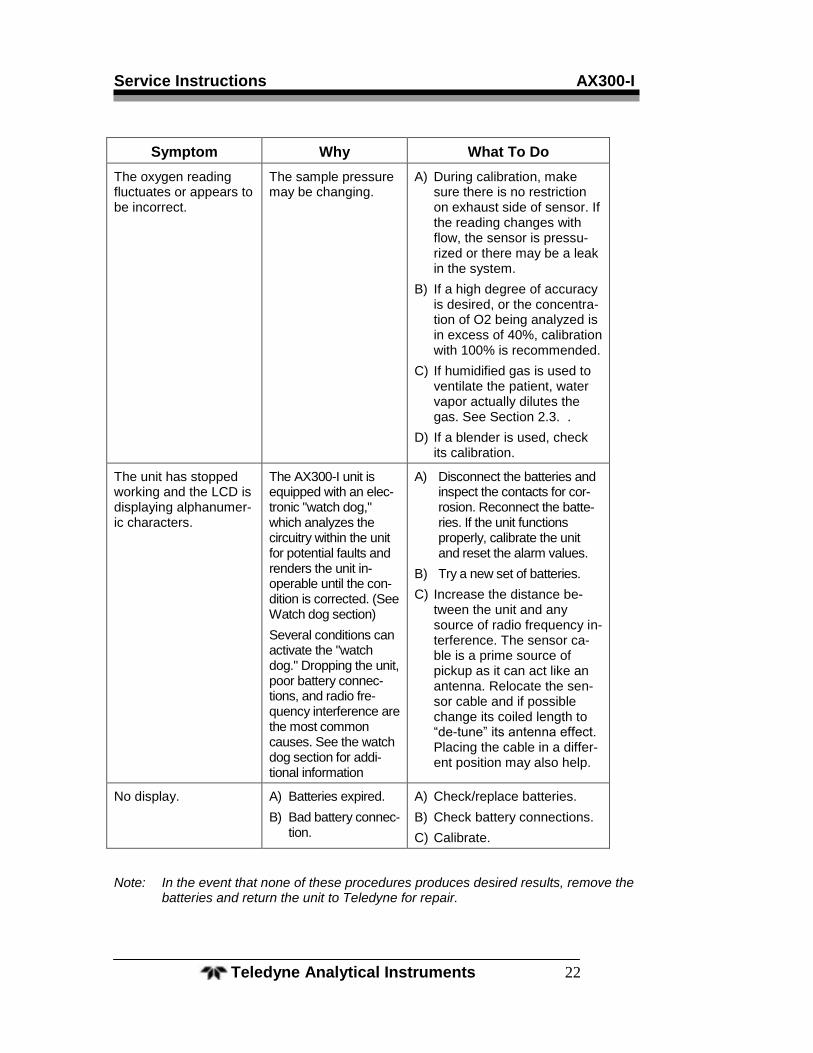
Symptom Why What To Do
The oxygen reading fluctuates or appears to be incorrect.
The sample pressure may be changing.
A) During calibration, make sure there is no restriction on exhaust side of sensor. If the reading changes with flow, the sensor is pressu-rized or there may be a leak in the system.
B) If a high degree of accuracy is desired, or the concentra-tion of O2 being analyzed is in excess of 40%, calibration with 100% is recommended.
C) If humidified gas is used to ventilate the patient, water vapor actually dilutes the gas. See Section 2.3. .
D) If a blender is used, check its calibration.
The unit has stopped working and the LCD is displaying alphanumer-ic characters.
The AX300-I unit is equipped with an elec-tronic "watch dog," which analyzes the circuitry within the unit for potential faults and renders the unit in-operable until the con-dition is corrected. (See Watch dog section)
Several conditions can activate the "watch dog." Dropping the unit, poor battery connec-tions, and radio fre-quency interference are the most common causes. See the watch dog section for addi-tional information
A) Disconnect the batteries and inspect the contacts for cor-rosion. Reconnect the batte-ries. If the unit functions properly, calibrate the unit and reset the alarm values.
B) Try a new set of batteries.
C) Increase the distance be-tween the unit and any source of radio frequency in-terference. The sensor ca-ble is a prime source of pickup as it can act like an antenna. Relocate the sen-sor cable and if possible change its coiled length to “de-tune” its antenna effect. Placing the cable in a differ-ent position may also help.
No display. A) Batteries expired.
B) Bad battery connec-tion.
A) Check/replace batteries.
B) Check battery connections.
C) Calibrate.
Note: In the event that none of these procedures produces desired results, remove the batteries and return the unit to Teledyne for repair.
Portable Oxygen Analyzer Service Instructions
Teledyne Analytical Instruments 23
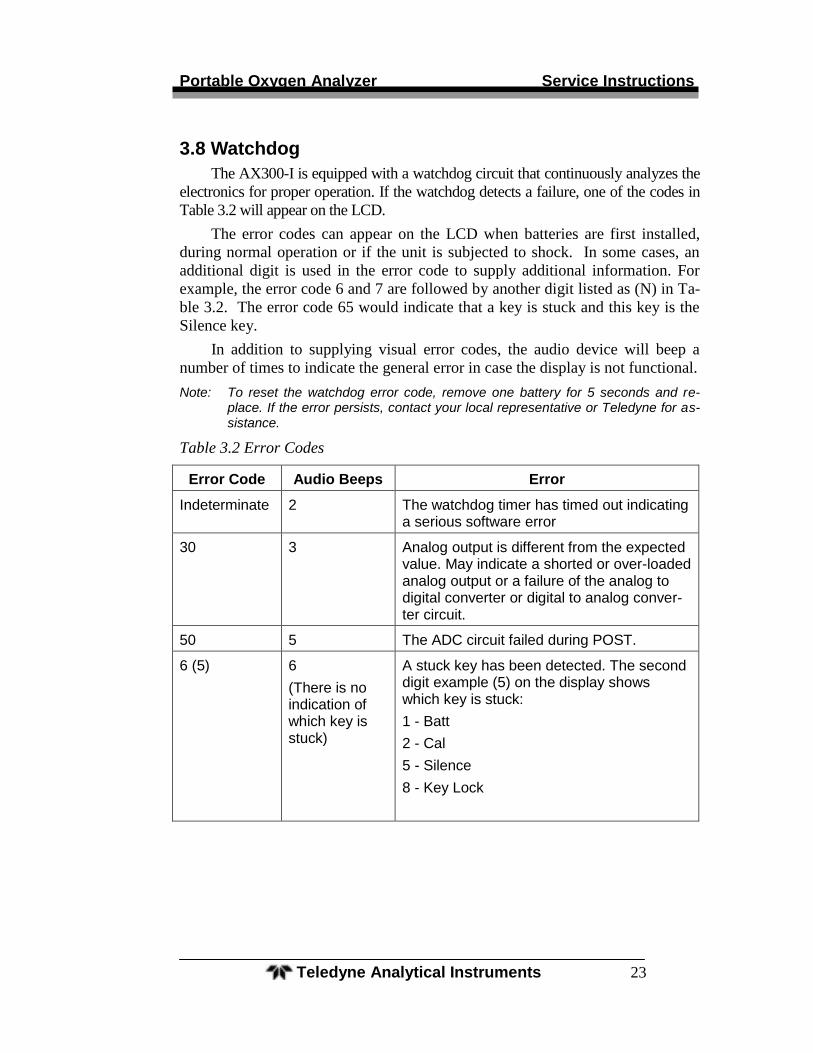
3.8 Watchdog
The AX300-I is equipped with a watchdog circuit that continuously analyzes the
electronics for proper operation. If the watchdog detects a failure, one of the codes in
Table 3.2 will appear on the LCD.
The error codes can appear on the LCD when batteries are first installed,
during normal operation or if the unit is subjected to shock. In some cases, an
additional digit is used in the error code to supply additional information. For
example, the error code 6 and 7 are followed by another digit listed as (N) in Ta-
ble 3.2. The error code 65 would indicate that a key is stuck and this key is the
Silence key.
In addition to supplying visual error codes, the audio device will beep a
number of times to indicate the general error in case the display is not functional.
Note: To reset the watchdog error code, remove one battery for 5 seconds and re-place. If the error persists, contact your local representative or Teledyne for as-sistance.
Table 3.2 Error Codes
Error Code Audio Beeps Error
Indeterminate 2 The watchdog timer has timed out indicating a serious software error
30 3 Analog output is different from the expected value. May indicate a shorted or over-loaded analog output or a failure of the analog to digital converter or digital to analog conver-ter circuit.
50 5 The ADC circuit failed during POST.
6 (5) 6
(There is no indication of which key is stuck)
A stuck key has been detected. The second digit example (5) on the display shows which key is stuck:
1 - Batt
2 - Cal
5 - Silence
8 - Key Lock
Service Instructions AX300-I
Teledyne Analytical Instruments 24
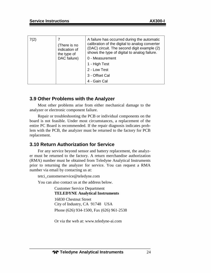
7(2) 7
(There is no indication of the type of DAC failure)
A failure has occurred during the automatic calibration of the digital to analog converter (DAC) circuit. The second digit example (2) shows the type of digital to analog failure.
0 - Measurement
1 - High Test
2 - Low Test
3 - Offset Cal
4 - Gain Cal
3.9 Other Problems with the Analyzer
Most other problems arise from either mechanical damage to the
analyzer or electronic component failure.
Repair or troubleshooting the PCB or individual components on the
board is not feasible. Under most circumstances, a replacement of the
entire PC Board is recommended. If the repair diagnosis indicates prob-
lem with the PCB, the analyzer must be returned to the factory for PCB
replacement.
3.10 Return Authorization for Service
For any service beyond sensor and battery replacement, the analyz-
er must be returned to the factory. A return merchandise authorization
(RMA) number must be obtained from Teledyne Analytical Instruments
prior to returning the analyzer for service. You can request a RMA
number via email by contacting us at:
You can also contact us at the address below.
Customer Service Department
TELEDYNE Analytical Instruments
16830 Chestnut Street
City of Industry, CA 91748 USA
Phone (626) 934-1500, Fax (626) 961-2538
Or via the web at: www.teledyne-ai.com
Portable Oxygen Analyzer Appendix
Teledyne Analytical Instruments 25
Appendix
A.1 Specifications
Range: 0-100% oxygen
Accuracy: +2% of full scale (at constant temperature
and pressure)
Response Time: 90% in less than 6 seconds at 25 °C
Battery Life: Approximately 2000 hours of continuous
use in non-alarm condition
System Power: 3 AA alkaline batteries.
Sensor Type: Class R17MED
Alarm: Non-adjustable SENSOR alarm
activates upon sensor problem or O2 con-
centration falls below 18%
Expected Life: 36 months in air at 25°C, Atmospheric
Pressure and 50% Relative Humidity.
(~7.5 months under similar conditions
when continuously exposed to 100% oxy-
gen)
Dimensions: 2.5" W × 1.25" D × 4.5" H (66 mm x 33-
mm × 111.5 mm)
Sensor Cable: Retracted: 2 ft / Extended: 10 ft.
Storage Temp. 10-30°C (continuous), 5-50°C (Intermit-
tent)
Operating Temp: 0-40°C
Appendix AX300-I
Teledyne Analytical Instruments 26
A.2 Spare Parts List
QTY PART NO DESCRIPTION
1 C43690-R17MED Micro-Fuel Cell R17MED with
flow diverter P/N B50057
3 B99 ―AA‖ size alkaline battery
1 C74721 Cable assembly
1 A268 Tee adapter (22 mm)
A.3 Optional Accessories
1 B50057 R17MED flow diverter
1 CP2345 Universal Pole Mounting Clamp
1 CP2344 ―V‖ mount Pole Clamp
1 B647 ―V‖ mount Wall Adapter
1 A51589 Sensor adapter cap, female (22 mm)
1 A51588 Sensor adapter cap, male (22 mm)
1 C53790 Calibration assembly
1 A284 Universal adapter set for pediatric
circuits (15mm)
1 A274 Tee adapter, autoclavable
1 A283 Tee adapter, metal
1 B75554 0-1 VDC Interface Cable
1 B75555 RS 232 Interface Cable
Schematics are available on request.
____________________
A minimum charge is applicable to spare parts orders.
Note: Orders for replacement parts should include the part number (if availa-ble) and the model and serial number of the analyzer for which the parts are intended.
Portable Oxygen Analyzer Appendix
Teledyne Analytical Instruments 27
Orders should be sent to:
TELEDYNE Analytical Instruments
16830 Chestnut Street
City of Industry, CA 91748 USA
Phone (626) 934-1500, Fax (626) 961-2538
Web: www.teledyne-ai.com
Or your local representative.