operating instructions safety-seal garlock …
TRANSCRIPT

15 Leaders in Sealing Integrity
OPERATING INSTRUCTIONSGARLOCK BUTTERFLY VALVESDN : 50 - 600 / 2“ - 24“PN : 10 / 16
GAR-SEAL SAFETY-SEALSTERILE-SEAL MOBILE-SEAL
TOXI-SEAL
Conformity declaration .................................................................................................. 16
Introduction ................................................................................................................... 17
Proper use ..................................................................................................................... 17
Safety information ......................................................................................................... 17
Transport and storage ................................................................................................... 19
Installation into the piping ............................................................................................. 19
Function test .................................................................................................................22
Normal operation and maintenance ..............................................................................22
Repair ............................................................................................................................23
In case of emergency....................................................................................................25
Further information .......................................................................................................25
0
1
2
3
4
5
6
7
8
9

16 Leaders in Sealing Integrity
Conformity declaration
EC directive for pressure equipment 2014/68/EU
Product: Lined Butterfly Valve
Type: GAR-SEAL, MOBILE-SEAL, SAFETY-SEAL, STERILE-SEAL, TOXI-SEAL
DN 50 - 600 / 2 - 24“, PN 10 (PN 16)
Developed, designed and manufactured in compliance with the above EC directive, in the sole
responsibility of
Company: Garlock GmbH, Falkenweg 1, 41468 Neuss
The following harmonizing norms and standards have been applied:
DIN EN 19 Industrial valves - Marking of metallic valves
DIN EN 1503 Valves - Materials for bodies, bonnets and covers
DIN EN 10213 Technical delivery conditions for steel castings for pressure purposes
The following other norms, directives and specifications have been applied:
AD 2000-Leaflet A 4 Bodies of equipment components
AD 2000- Leaflet W 0 Materials for pressure equipment – General principles for materials
DIN EN 558 Face-to-face and centre-to-face dimensions of metal industrial valves
DIN EN 1563 Spheroidal graphite cast irons
DIN EN ISO 5211 Industrial valves - Part-turn actuator attachments
DIN EN 12266 Testing of valves
DIN EN 12516 Industrial valves - Shell design strength
Suitable for: Fluid group 1 and 2
Conformity evaluation procedure: Module H1
The notified body TÜV Rheinland Industrie Service GmbH, Am Grauen Stein, 51105 Cologne, Identification
number 0035, is involved in the evaluation of the quality assurance system according to 2014/68/EU as well as to
examine the draft according to 2014/68/EU.
QS-System certificate no.: 01 202 926 / Q-01 0019
Draft examination no.: 1903461
Neuss, 2019-07-01 Marcus Viglahn
Managing Director

17 Leaders in Sealing Integrity
0 Introduction
In order to fully utilise Garlock valves to their optimum performance it is obligatory to observe this operating manual. The intention is to support the user during installation, operation and maintenance.
1 Proper use
Garlock valves are exclusively intended, upon installation on or between the flanges of piping system, to lock, conduct or regulate the flow of media within the permitted pressure and temperature limits.
The planning documents and technical data sheets of Garlock valves describe the permitted pressure and temperature ranges in relation to the lining material.
These valves must be installed on or between flanges according to EN 1092-1 (DIN 2501) or EN 1759-1, with sealing strips according to shape C, D or shape E, or flanges according to ANSI B 16.5 Class 150, which are processed plane-parallel and must be flush. Other flanges may only be installed upon release by Garlock.
When using the gasket, paragraph 2.2 < Safety information for the operator > must be observed.
2 Safety information
2.1 General safety information
The same safety requirements that apply to the piping system also apply to the valves that are installed in it. The safety instructions in these operating instructions are those for gaskets that have to be observed in addition.
2.2 Safety instructions for the operator
The following is not the responsibility of Garlock. Therefore the operator must ensure when operating the valve that
– the valve is only used properly as intended and described in paragraph 1.
– the piping system has been laid professionally and is checked regularly.
– the valve is professionally connected to the piping.
– in the piping system, the common flow speeds in permanent operation are not exceeded. Abnormal operational conditions such as vibrations, cavitation, erosion (e.g. by wet steam) and a proportion of solid matter in the medium – especially of the wearing kind – have been discussed with Garlock.
– at operating temperatures that result in hot or cold valve parts (incl. add-ons) and therefore might cause dangers, the operator provides protective measures against touching.
– manual levers, gearing or drives later installed on the valve are tuned to the valve and is adjusted to the two final positions of the valve – especially to closing position.
– only expert personnel operate and service the valve.
Attention
If the following; “Attention“, “Danger“ and “Note“ information is not observed this may result in poor operation, harm & possible warranty invalidation by Garlock.Garlock is available for any questions;addresses see paragraph 9 < Further information >.
Note
Garlock valves are not subject to Directive 2014/34/EU (“Atex 100 a“), as they have no potential source of ignition.For the areas where static discharging is likely, due to non-conductive media, we recommend the use of the “Antistatic version“ SAFETY-SEAL .
Attention
If a valve is used in continuous operation for regulation, the limits of application according to the planning documents and technical data sheets of Garlock Armaturen must be observed.Cavitation must always be avoided.

18 Leaders in Sealing Integrity
Danger to Life
No valve may be operated whose permitted pressure-temperature limits are not sufficient for the operating conditions: The permitted range is described in the planning documents and technical data sheets of Garlock Armaturen – see paragraph 9 <Further information>.For application outside this range release by Garlock is mandatory.Non-conformity with this regulation will result in danger for life and health and may cause damage in the piping system.
PTFE white, antistatic, abrasive
20
18
16
14
12
10
8
6
4
2
0
bar
DN 50 - DN 300/ 2“ - 12“
DN 40, 350 - 600/ 1½“, 14“ - 24“
P x T - Diagram GAR-SEAL Butterfly Valve
UHMWPE
-4 0 40 80 20 160 200 0 C
Note
In the planning documents and technical data sheets of Garlock Valves see paragraph 9<Further information> relevant information concerning selection of valves, installation dimensions, installation weights and valve structure are to be found.In case of doubt, please contact Garlock.
Danger to Life
It must be ensured that the selected materials of the parts of the valve with media contact are fit for purpose. Garlock will assume no liability for damage caused by corrosion of aggressive media.Non-conformity with this regulation will result in danger for life and health and may cause damage in the piping system.
Attention
In the case of a scheduled inspection of the pipeline system on transportable pressure equipment, a tightness test of the valve is recommended.
2.3 Special dangers
Danger to Life
Before removing the valve from the piping or before loosening the body screws the pressure in the piping must be completely relieved on both sides of the valve, ensuring there is no uncontrolled escape of medium.
Danger
If a valve has to be removed from piping, medium may escape from the piping or the valve. In case of unhealthy or dangerous media the piping must be completely emptied before the valve is removed. Be careful of residue that might be flowing out.
Danger
For valves used as a end-of-line valves:A blind flange should always be fitted and the valve should be locked in the “CLOSED” position to prevent unintentional opening. Exceptions are only permitted if a comprehensive written risk assessment for this situation has been prepared beforehand.
Danger
If a valve as an end-of-line valve in a pressure-conducting system is to be opened, utmost care should be taken, such that splashing medium cannot cause damage.Take due care when closing the end valve: Danger of crushing between valve disk and body!

19 Leaders in Sealing Integrity
2.4 Marketing
The Garlock valve is marked on the type label / on the body with the following data:
Type Label Line For Marking
GAR-SEAL 111-W-MT
GGG40.3 - PTFE - PTFEDN 150-63 PN 10
Ps=16 bar Tsmax=200 C06-05-2555
GARLOCK GmbH D-41468 NE.
0035
1 Type of valve GAR-SEAL
2 Type key 111-W-MT
3Material body/lining/disc
GGG40.3 (0.7043) / PTFE / PTFE
4 Nominal width pressure stage DN 150 – 6“ PN 16
5 Max. per. pressure, max. per. temp Ps 16 bar Ts max 200 °C
6 Serial No. (year of construction)Numbers 1-2: year, Numbers 3-4: month, Number 5-8: serial no.
7 For customer-specific marking
8 Garlock address Garlock GmbH, 41468 Neuss
9Conformity ID-no. named place
CE (conf. 2014/68/EU) 0035 (TÜV Rheinland Industrie Service GmbH)
3 Transport and storage
The Garlock GAR-SEAL valve must be handled, transported and stored with care:
– The valve must be stored and transported in its closed original packaging (including to the place of installation).
– The packaging protects the sensitive lining of the valve from damage.
– If the valve is stored before it is installed it should be stored in a closed room and be protected from dirt, humidity or ozone.
– The sealing surfaces of the flange ends for the piping connection are not damaged, neither by mechanical nor by other influences.
– Do not stack valves!
– The Garlock valve is supplied with slightly open valve disc (transport position approx. 10°). Therefore, it must be stored in the way it is supplied. The locking valve must not be operated.
Type Label Line For Marking
MOBIL-SEAL 111-W-TW-MT
GGG40.3 - PTFE - PTFEDN 050-2” PN 10
Ps=10 bar T -40 / +200 C18-12-255514432-2014
GARLOCK GmbH D-41468 NE.
0035
1 Type of valve MOBIL-SEAL
2 Type key 111-W-TW-MT
3Material body/lining/disc
GGG40.3 (0.7043) / PTFE / PTFE
4 Nominal width pressure stage DN 050 – 2“ PN 10
5 Max. per. pressure, max. per. temp Ps 10 bar T -40 / +200 °C
6 Serial No. (year of construction)Numbers 1-2: year, Numbers 3-4: month, Number 5-8: serial no.
7 Norm EN 14432 - 2014
8 Garlock address Garlock GmbH, 41468 Neuss
9Conformity ID-no. named place
CE (conf. 2014/68/EU) 0035 (TÜV Rheinland Industrie Service GmbH)
Attention
Do not take off manual lever, gearing or drive while being in operation situation of pressure!

20 Leaders in Sealing Integrity
DN Inch 2 2½ 3 4 5 6 8 10 12 14 16 18 20 24
mm 50 65 80 100 125 150 200 250 300 350 400 450 500 600
Di mm 61 71 83 106 128 158 208 259 310 336 388 431 485 579
Da mm 107 127 142 162 192 218 273 328 378 438 490 540 595 695
Garlock recommends a seal thickness of 3.2 mm.
Danger to Life
If – in exceptional cases – a valve without drive unit must be installed, it must be ensured that such a valve is not exposed to pressure. If a drive unit is retrofitted the nominal torque and the setting of the final stops must be tuned to “OPEN” and “CLOSED” of the valve.Non-observation this regulation may result in danger of life and health and may cause damage in the piping system.
4.2 Preparations
It must be ensured that only such Garlock valves are installed whose pressure class, connection type and dimensions are compliant with the conditions of application. See marking of the valve.
Danger to Life
No valve may be installed which permitted pressure-temperature limits are not sufficient for the operating conditions: The pressure- and temperature limits are marked on the valve, the permitted range of application depending on the lining material (see type label) is described in the Garlock planning documents – see paragraph 9 <Further information>.Non-observation this regulation may result in danger for life and health and may cause damage in the piping system.In case of doubt, please contact Garlock.
– Take Garlock valves out of their original packaging and remove all accompanying materials and clean off any dirt.
– Check Garlock valves for transport damage. Do not install damaged valves.
– Following prolonged storage of approx. six months or more, retighten the housing screws before installation to the torques specified in point 7.1.
– Garlock butterfly valves are designed to be fitted between flanges as per EN 1092-1 (DIN 2501) PN 10 (PN16) / ASME B 16.5 class 150 as standard. MOBILE-SEAL valves can also be used installation between flanges according to DIN 28459. Other flanges may only be used upon release by Garlock.
4 Installation into the piping
4.1. General
For installation of Garlock valves into piping systems the same instructions apply as for connection of pipes and similar piping elements.
The following instructions are to be additionally observed for valves.
For transport to the installation location, paragraph 3 <Transport and storage> must be observed.
Note
Garlock valves should be installed without additional gaskets.However, in case of rough or uneven sealing surfaces, a flange gasket is preferable. If you produce them yourself, please observe the dimensions in the following table. These dimensions are not compliant with a norm but are adjusted to the gaskets.We do not recommend using metal enforced seals or soft seals with metal inserts, as this may cause damage to the body lining.We recommend using Garlock GYLON Blue, Style 3504 flat sealing material.
Danger
Valves that are supplied without manual lever / gearing or drive:The valve disc is not secured against moving. It must not open from its locked position due to outside influences (e.g. vibration).

21 Leaders in Sealing Integrity
– Thoroughly clean the connecting end and the adjoining piping system, ensuring the lining is not damaged by debris.
– The connecting ends of the piping must be flush and plane parallel.
4.3 Installation
– GARLOCK butterfly valves can be fitted regardless of the direction of flow and position of the butterfly valve stem.
– The angle between the butterfly valve and pipe axle can be freely set by the user. It is, however, recommended that they be fitted with the shifter shaft horizontal, especially for media containing solids; the bottom part of the disc will then open in the direction of flow. The position of the disc is indicated by the dihedral (DN 50 to DN 300) or the feather key groove (≥ DN350) if the shaft end is open, by the hand lever if one is fitted, and by a position indicator if a worm gear is fitted.
– The disc must be partially open when the butterfly valve is fitted. – The butterfly valve must be carefully centred when being fitted. – The applicable standards must be observed for the tightening torques of the flanged connection. Boundary
conditions such as temperature, pressure, type of screws, lubrication of screws, type of flanges etc. must also be taken into account. The values contained in the VCI’s “Guidelines for flanged connections” can be used as guide values.
Attention
Connecting ends of the piping that are not flush / not parallel may damage the lining of the valve.
Attention
Exactly center Garlock valves and install with slightly opened valve disc (transport position approx. 10°).By means of test switching, ensure that the valve disc is freely movable and that the valve disc does not drive against the inside edges of the flange when opening.
Attention
Tighten flange screws evenly and crosswise with a spanner.Tightening torques according to the following table ensure sufficient crimping forces for secure outward sealing.
DNInch 2 2½ 3 4 5 6 8 10 12 14 16 18 20 24
mm 50 65 80 100 125 150 200 250 300 350 400 450 500 600
A mm 43 46 46 52 56 56 60 68 78 92 102 114 127 154
C mm 43 53 67 93 115 147 188 236 284 322 374 415 467 558
Danger
The inside diameter of the piping (flanges) must be bigger than the part of the valve disc, which in an opened position extends over the valve, ensuring the valve disc is not damaged when moving outward. See measurement C of the following table.If necessary, use intermediate rings.
Attention
The installation space between the flanges must provide sufficient clamping width = width of the body lining. See measurement A of the following table.If necessary, use intermediate rings.

22 Leaders in Sealing Integrity
ThreadTightening torque [Nm]a
Tightening methodSeal group A
M12 50With manual spanner and suitable extension
if necessaryM16 125b
M20 240c
M24 340
With torque spanner or other torque-controlled method
M27 500
M30 700
M33 900
M36 1200
M39 1400
M45 2000
M52 3000a These tightening torques have been calculated by BASF SE and confirmed by way of spot checks by the cooperating companies.b Recommended lever length 300 mm c Recommended lever length 550 mm
Extract from VCI’s “Guidelines for flanged connections” Table 6 seal group A, March 2016 edition.
Table 6 – Required tightening torques for fitting flanges in accordance with DIN EN 1092-1 type 11 and fasteners (e.g. screws, threaded rod) made of 25CrMo4 / A2-70 or similar strength
Note: Flanges made of austenitic steel and ferrite as per DIN EN 1092-1 are isometric.
5 Function test
First flush newly installed piping systems carefully in order to remove all debris.The locking function of the installed Garlock valve must be checked by repeated opening and closing. The pressure test of the valves has already been conducted by Garlock.Please observe the following for the pressure test of a piping system with installed valves:
Valve open: The test pressure (PT) must not exceed the value 1.5 x (PS) (acc. to type label). Valve closed: The test pressure (PT) must not exceed the value 1.1 x (PS) (acc. to type label).
If leakage occurs at a valve, follow paragraph 8 < In case of emergency>.
6 Normal operation and maintenance
As the plastic sealing surfaces incline towards the flow it may be necessary, during commissioning and after reaching the operating temperature, to re-tighten all flange connections between piping and gasket using the respective torque according to tables in 4.3 Installation.For manual operation (manual lever / gearing) normal manual forces are sufficient. Using extensions to increase the operating torque are not permitted.
23 Leaders in Sealing Integrity
Note
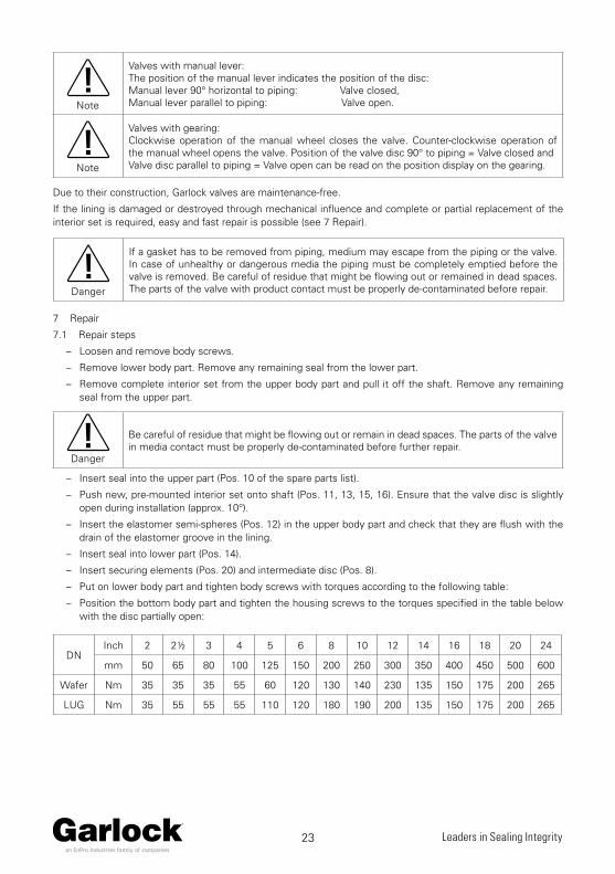
Valves with manual lever:The position of the manual lever indicates the position of the disc: Manual lever 90° horizontal to piping: Valve closed,Manual lever parallel to piping: Valve open.
Note
Valves with gearing:Clockwise operation of the manual wheel closes the valve. Counter-clockwise operation of the manual wheel opens the valve. Position of the valve disc 90° to piping = Valve closed andValve disc parallel to piping = Valve open can be read on the position display on the gearing.
Due to their construction, Garlock valves are maintenance-free.
If the lining is damaged or destroyed through mechanical influence and complete or partial replacement of the interior set is required, easy and fast repair is possible (see 7 Repair).
Danger
If a gasket has to be removed from piping, medium may escape from the piping or the valve. In case of unhealthy or dangerous media the piping must be completely emptied before the valve is removed. Be careful of residue that might be flowing out or remained in dead spaces. The parts of the valve with product contact must be properly de-contaminated before repair.
7 Repair
7.1 Repair steps
– Loosen and remove body screws.
– Remove lower body part. Remove any remaining seal from the lower part.
– Remove complete interior set from the upper body part and pull it off the shaft. Remove any remaining seal from the upper part.
Danger
Be careful of residue that might be flowing out or remain in dead spaces. The parts of the valve in media contact must be properly de-contaminated before further repair.
– Insert seal into the upper part (Pos. 10 of the spare parts list).
– Push new, pre-mounted interior set onto shaft (Pos. 11, 13, 15, 16). Ensure that the valve disc is slightly open during installation (approx. 10°).
– Insert the elastomer semi-spheres (Pos. 12) in the upper body part and check that they are flush with the drain of the elastomer groove in the lining.
– Insert seal into lower part (Pos. 14).
– Insert securing elements (Pos. 20) and intermediate disc (Pos. 8).
– Put on lower body part and tighten body screws with torques according to the following table:
– Position the bottom body part and tighten the housing screws to the torques specified in the table below with the disc partially open:
DNInch 2 2½ 3 4 5 6 8 10 12 14 16 18 20 24
mm 50 65 80 100 125 150 200 250 300 350 400 450 500 600
Wafer Nm 35 35 35 55 60 120 130 140 230 135 150 175 200 265
LUG Nm 35 55 55 55 110 120 180 190 200 135 150 175 200 265

24 Leaders in Sealing Integrity
– Turn valve disc open and close repeatedly, so that the elastomer semi spheres can settle in the elastomer groove of the lining.
– Before installing into the system, check valve for tightness. If leakage occurs at a valve, follow paragraph 8 < In case of emergency >.
7.2 Spare parts list
Pos. Designation1 Feed Shaft (one part)2 Upper feed shaft bearing3 Middle feed shaft bearing4 Lower feed shaft bearing5 Body (two parts)6 Holding ring7 Spring ring
81, 2 Washer9 Body screw
101, 2 Seal (upper part)111, 2 Body lining121, 2 Elastomer semi-sphere131 Valve disc
141, 2 Seal (lower part)151, 2 Seal ring161, 2 O-ring (seal ring)17 Type label18 Grooved stud19 O-fing (feed shaft)
201, 2 Securing element
22 O-ring (head flange)
25 Screw26 Spring ring27 Head flange28 Seal (head flange)
1 = Spare parts kit for fully lined valves
2 = Spare parts kit for valves with metallic disc

25 Leaders in Sealing Integrity
8 In case of emergency
8.1 General
9 Further information
The mentioned planning documents and technical data sheets of Garlock Valves as well as further information and advice can be obtained – also in other languages – at the following address:
Garlock GmbH, Falkenweg 1, 41468 Neuss – Phone: +49 (0) 21 31 349 – 0, Email: [email protected]
8.2 Trouble and remedy
Note
All repair and maintenance works must be carried out by qualified skilled personnel using suitable tools and original spare parts.The safety and danger information above must be observed.
Trouble
Leakage on the flanges
Leakage at the closure
Leakage on the shaft
Torque too high
Valve does not open
Valve does not close
Possible cause Remedy
Incorrect flanging
Check flange type and re-tighten screws with prescribed torque acc. to 4.3
– If no improvement increase torque by 10 % – If still no improvement
-> contact Garlock
Flanges not plane parallelRe-align flanges and tighten screws with prescribed torque acc. to 4.3
Debris in the valveOpen empty / flow-free piping Remove debrisCheck lining and valve disc for damage
-> Replace defective parts with spare parts kit
Valve disc damaged/ corroded
Open empty / flow-free pipingCheck flange connection (see 4.2 measurement C with inside diameter piping)
-> Replace defective disc with spare parts kit
Lining worn, damagedOpen empty / flow-free pipingCheck lining and valve disc for damage
-> Replace defective parts with spare parts kit
Worm shaft twisted (broken)Open empty / flow-free piping Check lining / valve disc for damage
-> Replace defective worm shaft
Manual lever / gearing / drive damaged (defective)
Check dimension data-> Replace defective parts or replace with other parts

Technical details subject to change without notice. INT-D50 . 2.3-NHK . 07/2019
GARLOCK GMBHan EnPro Industries family of companies
Falkenweg 1, 41468 Neuss, Germany
Tel: +49 2131 349 0
www.garlock.com
Garlock Sealing Technologies
GPT
Garlock PTY
Garlock India Private Limited
Garlock de Canada, LTD
Garlock China
Garlock Singapore
Garlock USA
Garlock de Mexico, S.A. De C.V.
Garlock New Zealand
Garlock Great Britain Limited
Garlock Middle East