operating instructions instrucciones de operación · no. de artículo no. de refacción nombre del...
TRANSCRIPT
THANKS FOR READING THIS MANUAL. IF YOU HAVE ANY DOUBT REGARDING THE
OPERATION OF THIS VEGETABLE CUTTER, PLEASE CONTACT TO YOUR BLAZER
AUTHORIZED DEALER.
GRACIAS POR LEER ESTE MANUAL. SI UD. TIENE ALGUNA DUDA SOBRE LA OPERACIÓN DE
ESTE PROCESADOR DE VEGETALES, POR FAVOR CONTACTE A SU DISTRIBUIDOR BLAZER
AUTORIZADO
507577-0
Operating Instructions
Instrucciones de Operación
NEW STAINLESS STEEL VEGETABLE CUTTER
LEA LAS INSTRUCCIONES ANTES DE USAR EL EQUIPO
POR PRIMERA VEZ
READ THIS MANUAL BEFORE USING THE EQUIPMENT FOR THE FIRST
TIME
PROCESADOR DE VEGETALES DE ACERO INOXIDABLE

Owner´s manual
1
ENGLISH
2 INTRODUCTION…………………………………………………………..……………..…………...2
TECHNICAL FEATURES…………………………………………………..…………………….…….3
2.1 Scope of application
2.2 Technical data
2.3 Shredding cutters types
2.4 Description of the machine design
CUTTER INSTALLATION.........................................................................................................6
3.1 Preparation for installation
3.2 Electric diagrams
3.3 Connection to mains and test run
CUTTER OPERATION..............................................................................................................8
4.1 Fixing shredding discs and the feeding box
4.2 Dicing set
4.2.1 Removal of the cube set after use, when the scraper was used
4.3 Requirements for shredded food
4.4 Activities after completing the shredding process
4.5 Periodical maintenance
4.6 Methods of fixing operating faults
5. SPARE PARTS CATALOGUE………………………………………..…………….…….......….12
TABLE OF CONTENT
In the machine PV-300 i.e. with speed control, in order to obtain the optimum quality,
performance and functionality of cutting, the speed has to be adjusted to the type and kind of
the cutting blade and the kind of cut material, applying the rule:
A heavy cut - like dice vegetables, French fries – slower turnover
A thin cut - like minor chips, pulp – faster turnover
Note
Manual de Usuario
14
No. de artículo No. de refacción Nombre del elemento
75 6210 Disco para cortar chips medianas de 8 x 10 mm (F-8)
76 6215 Disco para cortar chips estándar de 10 x 10 mm (F-10)
77 6220 Disco para cortar chips gruesas de 12 x 10 mm (F-12)
78 6230 Kit de corte en cubos - 10 x 10 x 10 mm (K-15)
79 6235 Disco en malla para cortar en cubos 10 x 10 mm
80 6240 Kit de corte en cubos - 15 x 15 x 10 mm (K-10)
81 6245 Disco en malla para cortar en cubos 15 x 15 mm
82 6250 Kit de corte en cubos - 7.5 x 7.5 x 10 mm (K-7.5)
83 6255 Disco en malla para cortar en cubos 7.5 x 7.5 mm
84 6260 Elemento de rotación el kit de corte cubicado - artículos 73-76
85 6261 Cortador de cubos
86 6263 Vaina de montaje
Nota 1:
Nota 2:
Al cortar papas en rebanadas, un pequeño porcentaje de la masa del producto puede desecharse
(hasta 20%) en forma de piezas pequeñas o tiras irregulares. La calidad de triturado obtenido
depende del tamaño de las papas, su forma y su calidad. El material desechado puede usarse para
diferentes propósitos, por ejemplo, para molerlo y hacer pulpa para hacer pasteles de papa
Tabla de configuraciones óptimas de la perilla reguladora
ProductoPapas a la
FrancesaRebanadas Pulpa Chips Cubo 1 1.5 2 2.5 3 3.5 4 4.5 5 Tubo Orificio
Pepino x x x
Zanahoria x x x
Zanahoria x x x x
Papa x x x x
Papa x x x
Papa x x x
Apio/Jícama x1 x x
Apio 2/Jícama 2 x x x
Apio/Jícama x3 x x
Tomate x x x
Tomate x x x
Cebolla x x x
Cebolla x x x
Tipo de ProductoTipo de corte Posición de la perilla
1. Chips (rebanadas) “7”
2. Corte el apio en cubos solo después de suavizarlo
3. El apio y jícama crudos pueden cortarse en cubos al ser colocados en la canaleta de entrada en
trozos individuales
The appliance is not be used by persons (including children) with reduced
physical, sensory or mental capabilities, or lack of experience and knowledge,
unless they have given supervision or instruction. Children being supervised not
play with the appliance.
Never perform service, cleaning or maintenance on this unit while is connected
to a power source.
Keep the guard closed during work, check that the lock is completely into its
hole.
Do not leave the machine unattended while in operation & turn it off when it is
not being used.
Warning! Never introduce hands or fingers within the feeding area where the
knives are rolling.

1. INTRODUCTION
1.1 PV 300 cutters is a state-of-the-art culinary machine meeting the requirements for applicable
standards as far as hygiene and safety are concerned.
1.2. A vegetable cutter may be connected only to a plug-in socket with an earthing pin (see 3.3).
1.3. Adhering to the guidelines provided in the Manual and operating the machine in a compatible
manner with its scope of application will ensure a safe and prolonged operation.
1.4. The manufacturer is not responsible for any consequences of using the machine in an
incompatible manner with this Manual.
1.5. The machine PV-300 come with power supply methods 120V 1-phase current with revolutions
adjustment.
1.6. The manufacturer recommends purchasing a start-up set for 4 cutting discs for the PV-300. A
user may purchase a larger number of cutters of different types and a dicing set as an add-on feature
not requiring any modifications.
1.7. The noise level on the operator’s station in standard operating conditions (height 1.6 m, distance
from the machine - 1 m) does not exceed 70 dB.
1.8. For this equipment the manufacturer recommends setting of the adjustment knob according to
“the Table of optimal settings of regular knob” attached at the end of this manual (Note 2)
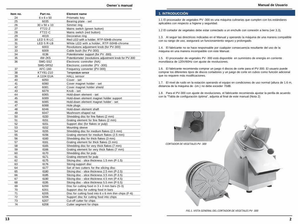
Fig. 1 General view of the PV-300 Vegetable Cutter
FOR VEGETABLE CUTTER PV-300
Owner´s manual Manual de Usuario
13 2
No. de artículo No. de refacción Nombre del elemento
24 6 x 6 x 50 Cuña
25 6035 Placa de soporte - kit
26 30 x 50 x 10 Aro simmer
27 FT22-Z Interruptor de red (botón verde)
28 FT22-C Interruptor de red (botón rojo)
29 4019 Aro decorativo
30 LED 5 R-LC LED rojo con soporte, RTP-50HB-cromo
31 LED 5 R-LB LED blanco con soporte, RTP-50HB-cromo
32 6003 Perilla de ajuste de revoluciones
33 6009 Pasacables
34 6136 Soporte del potenciómetro
35 4W-2K5 Potenciómetro (Perilla de ajuste de revoluciones )
36 SMG-SS2 Controlador eléctrico (NA)
SMG-SRS2 Controlador eléctrico (PV-300)
37 AFC-160 Convertidos de frecuencia (para PV-300)
38 KTY81-210 Sensor de temperatura
39 A 1104 EUA Sensor HALL
40 6050 Cubierta – juego
41 6080 Soporte magnético de la cubierta- kit
42 6081 Protector del soporte magnético de la cubierta
43 6079 Perilla - juego
44 6065 Elemento sujetador - juego
45 6089 Soporte magnético del elemento sujetador
46 6085 Soporte magnético del elemento sujetador - juego
47 6088 Tapones de orificio
48 6046 Elemento sujetador del mango - juego
49 6047 Tuerca bellota
50 6150 Disco triturador para hojuelas finas (2 mm)
51 6151 Elemento rallador para hojuelas finas (2 mm)
52 6151 Disco de soporte (para hojuelas o pulpa)
53 6152 Cubierta de montaje
54 6155 Disco triturador para hojuelas medias (2.5 mm)
55 6156 Elemento rallador para hojuelas medias (2.5 mm)
56 6160 Disco triturador para hojuelas gruesas (3 mm)
57 6161 Elemento rallador para hojuelas gruesas (3 mm)
58 6165 Disco triturador para hojuelas muy gruesas (7 mm)
59 6166 Elemento rallador para hojuelas muy gruesas (7 mm)
60 6170 Disco triturador para pulpa
61 6171 Elemento rallador para pulpa
62 6175 Disco rebanador - grosor de la rebanada 1.5 mm (P-1.5)
63 6176 Disco de soporte rebanador
64 6177 Juego de dos cortadores para disco rebanador
65 6180 Disco rebanador - grosor de la rebanada 2.5 mm (P-2.5)
66 6185 Disco rebanador - grosor de la rebanada 3.5 mm (P-3.5)
67 6190 Disco rebanador - grosor de la rebanada 4.5 mm (P-4.5)
68 6195 Disco rebanador - grosor de la rebanada 5.5 mm (P-455)
69 6200 Disco para cortar alimentos en barras de 3 x 3 mm (S-3)
70 6201 Disco de soporte para cortar alimentos en barras
71 6205 Disco para cortar alimentos en chips delgados de 6 x 6 mm (F-6)
72 6206 Disco de soporte para cortar alimentos en chips
73 6207 Cortador para capas
74 6208 Segmento cortador para capas
5. CATALOGO DE REFACCIONES
2.1 Scope of application
The vegetable cutter may be used for cutting all types of raw vegetables and fruit into slices, chips, flakes,
and pulp or, when an attachment is used, for dicing and shredding cheese. PV-300 may be used in catering
establishments and food processing plants. Its scope of application includes small and large catering
establishment, e.g. kindergartens, schools, hospitals, military units and other catering facilities, hotels,
canteens, restaurants, pizzerias, fast food bars, salad bars and small fruit-vegetable processing plants. It
mostly eliminates the effort required to shred fruit and vegetables manually and ensures cost savings as the
meal preparation time is reduced.
2.2 Technical data
Set of slicing discs (2 cutters)
P-1.5 slices 1.5 mm
P-2.5 slices 2.5 mm
P-3.5 slices 3.5 mm
P-4.5 slices 4.5 mm
P-5.5 slices 5.5 mm
Set of chips discs
F-6 thin chips 6 x 6 mm
F-8 medium chips 8 x 8 mm
F-10 standard chips 10 x 10 mm
F-12 thick chips 12 x 10 mm
S-2 standard sticks 2 x 23 mm
S-3 standard sticks 3 x 3 mm
Set of pulp disc
Flake cutters
W-2 Fine flakes 2 mm
W-2.5 Medium flakes 2.5 mm
W-3 Thick flakes 3 mm
W-7 Very thick flakes 0.7 mm
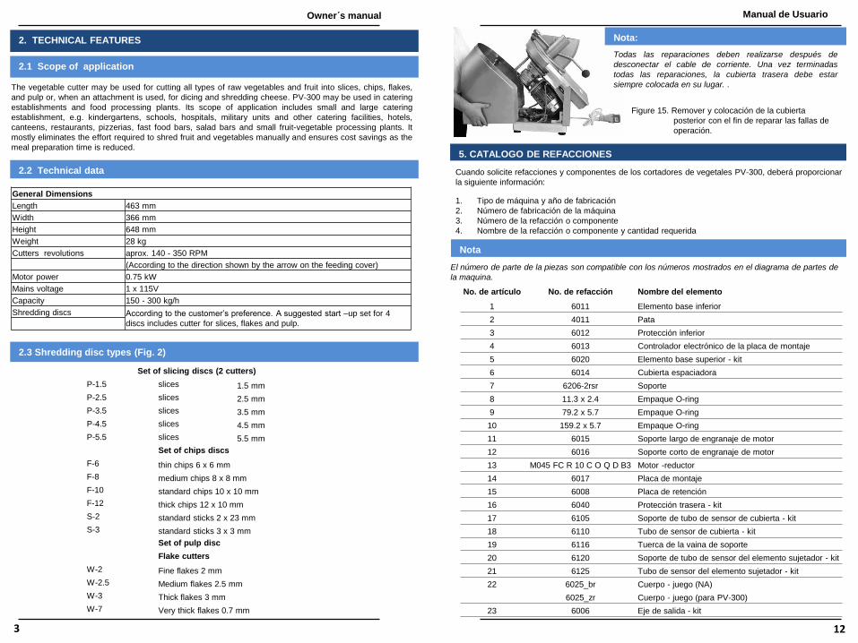
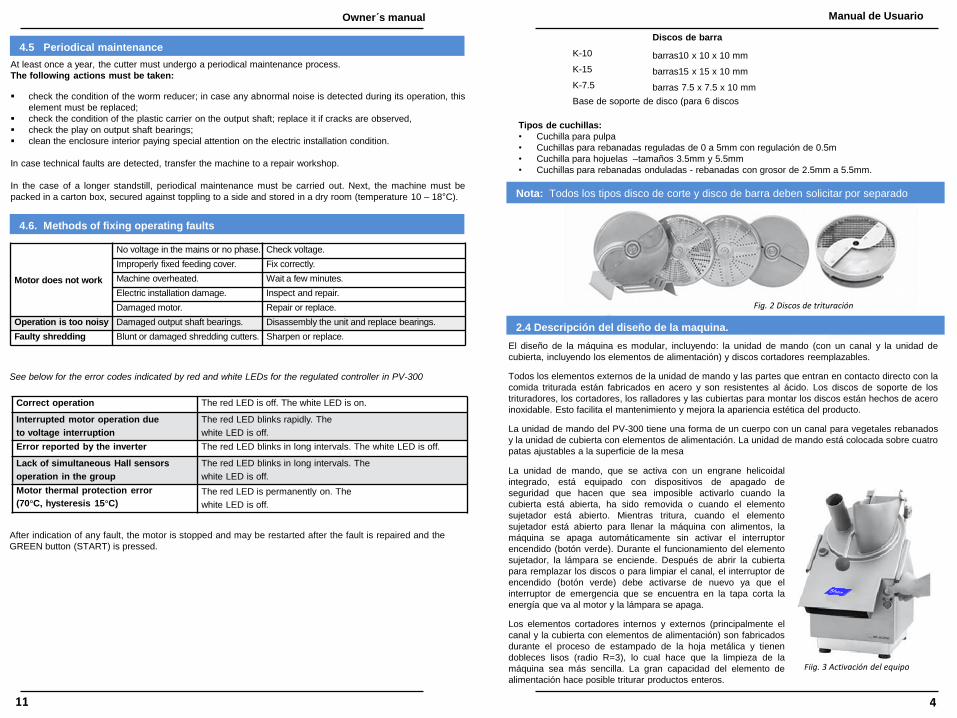
2.3 Shredding disc types (Fig. 2)
General Dimensions
Length 463 mm
Width 366 mm
Height 648 mm
Weight 28 kg
Cutters revolutions aprox. 140 - 350 RPM
(According to the direction shown by the arrow on the feeding cover)
Motor power 0.75 kW
Mains voltage 1 x 115V
Capacity 150 - 300 kg/h
Shredding discs According to the customer’s preference. A suggested start –up set for 4
discs includes cutter for slices, flakes and pulp.
Owner´s manual Manual de Usuario
3 12
Todas las reparaciones deben realizarse después de
desconectar el cable de corriente. Una vez terminadas
todas las reparaciones, la cubierta trasera debe estar
siempre colocada en su lugar. .
Nota:
Figure 15. Remover y colocación de la cubierta
posterior con el fin de reparar las fallas de
operación.
Cuando solicite refacciones y componentes de los cortadores de vegetales PV-300, deberá proporcionar
la siguiente información:
1. Tipo de máquina y año de fabricación
2. Número de fabricación de la máquina
3. Número de la refacción o componente
4. Nombre de la refacción o componente y cantidad requerida
Nota
El número de parte de la piezas son compatible con los números mostrados en el diagrama de partes de
la maquina.
No. de artículo No. de refacción Nombre del elemento
1 6011 Elemento base inferior
2 4011 Pata
3 6012 Protección inferior
4 6013 Controlador electrónico de la placa de montaje
5 6020 Elemento base superior - kit
6 6014 Cubierta espaciadora
7 6206-2rsr Soporte
8 11.3 x 2.4 Empaque O-ring
9 79.2 x 5.7 Empaque O-ring
10 159.2 x 5.7 Empaque O-ring
11 6015 Soporte largo de engranaje de motor
12 6016 Soporte corto de engranaje de motor
13 M045 FC R 10 C O Q D B3 Motor -reductor
14 6017 Placa de montaje
15 6008 Placa de retención
16 6040 Protección trasera - kit
17 6105 Soporte de tubo de sensor de cubierta - kit
18 6110 Tubo de sensor de cubierta - kit
19 6116 Tuerca de la vaina de soporte
20 6120 Soporte de tubo de sensor del elemento sujetador - kit
21 6125 Tubo de sensor del elemento sujetador - kit
22 6025_br Cuerpo - juego (NA)
6025_zr Cuerpo - juego (para PV-300)
23 6006 Eje de salida - kit
2. TECHNICAL FEATURES

Bars discs
K-10 bars10 x 10 x 10 mm
K-15 bars15 x 15 x 10 mm
K-7.5 bars 7.5 x 7.5 x 10 mm
Support disc base (for 6 discs)
Kinds of cutting blades:
• Blade for pulp
• Blades for regulated slices from 0 to 5mm with regulation each 0,5m
• Falcate blade – sizes 3,5mm and 5,5mm
• Blades for wave slices – slices thickness from 2,5mm to 5,5mm
Note: All cutter types and the dicing set must be ordered separately.
Fig. 2 Shredding discs
2.4 Description of the machine
design. The machine design is modular including: the drive unit (with a trough and the cover unit including
feeding elements) and replaceable cutting discs.
All external elements of the drive unit and parts coming in direct contact with shredded food are made
of steel and acid-resistant elements. The support discs of shredding cutters, cutting cutters, grating
elements and the disc mounting sleeves are made of stainless steel. This facilitates the maintenance
of hygiene and enhances the product aesthetic appearance.
Fig. 3 Activating the machine
The vegetable cutter drive unit has a form of a body with a
trough for sliced vegetables and the cover unit with feeding
elements. The drive unit is situated over four adjustable feet for
the table surface.
The drive unit, powered by an integrated worm gear is equipped
with magnetic safety shutoff devices making it impossible to
activate the drive when the cover is opened or removed or the
hold-down element is opened. While shredding, whenever the
hold-down element is opened to fill the machine with food, the
machine switches off automatically without activating the mains
switch (green button). During hold-down element operation, the
lamp is on. After opening the cover to replace the discs or clean
the trough, the mains switch (green button) must be activated
again as the emergency switch located on the flap cuts off the
power supply to the motor and the lamp is turned off.
External and internal cutter elements (mostly the trough and
cover with feeding elements) are manufactured within the sheet
metal stamping process and have smooth bends (radius R = 3),
which facilitates the machine cleaning. The Large capacity of the feeding element makes it possible to shred whole products.
4.5 Mantenimiento Periódico
El PV-300 debe tener un proceso de mantenimiento periódico por lo menos una vez al año.
Las siguientes acciones deben ser realizadas:
revise la condición del reductor sin fin; en caso de ruidos anormales durante el funcionamiento, este
elemento debe ser remplazado;
revise la condición del limpiador de plástico en el eje de salida; debe ser remplazado si observa grietas,
revise el juego del los baleros del eje de salida;
limpie el interior de la carcasa poniendo especial atención a la condición de la instalación eléctrica.
En caso de que se detecten fallas técnicas, lleve su equipos con su distribuidor autorizado.
En caso de que la máquina no sea usada por largos periodos de tiempo, debe realizar un mantenimiento
periódico. Después, la máquina debe ser empacada en una caja de cartón, protegida de riesgos de caída y
guardada en una habitación seca (temperatura 10-18ºC)
Manual de Usuario Owner´s manual
11 4
El motor no funciona.
No hay voltaje en la red o no hay una fase. Revisar potencia.
La cubierta de alimentación no está ajustada
correctamente. Ajustar correctamente.
Sobrecalentamiento de la máquina. Esperar unos minutos.
Daño en la instalación eléctrica. Inspeccionar y reparar.
Motor dañado. Reparar o remplazar.
Mucho ruido durante el
funcionamiento. Balero del eje de salida dañado.
Desarmar la unidad y remplazar
los baleros.
Triturado defectuoso Trituradores dañados o sin filo. Afilar o remplazar.
4.6 Métodos para reparar fallas de funcionamiento
Ver abajo los códigos de error indicados por los LED rojo y blanco para el controlador regulado del PV-300
Funcionamiento correcto. El LED rojo está apagado. El LED blanco está encendido.
Funcionamiento del motor interrumpido por
interrupción de potencia. El LED rojo parpadea rápidamente.
El LED blanco está apagado.
Error reportado por el convertidor. El LED rojo parpadea por largos períodos de tiempo.
El LED blanco está apagado.
Falta de funcionamiento de sensores Hall
simultáneos en el grupo. El LED rojo parpadea por largos períodos de tiempo.
El LED blanco está apagado.
Error en la protección térmica del motor. (70°C,
histeresis 15°C) El LED rojo está encendido permanentemente.
El LED blanco está apagado.
Después de la indicación de alguna falla, el motor se detiene y puede ser reiniciado después que la falla
haya sido reparada y el botón VERDE (INICIO) sea presionado.

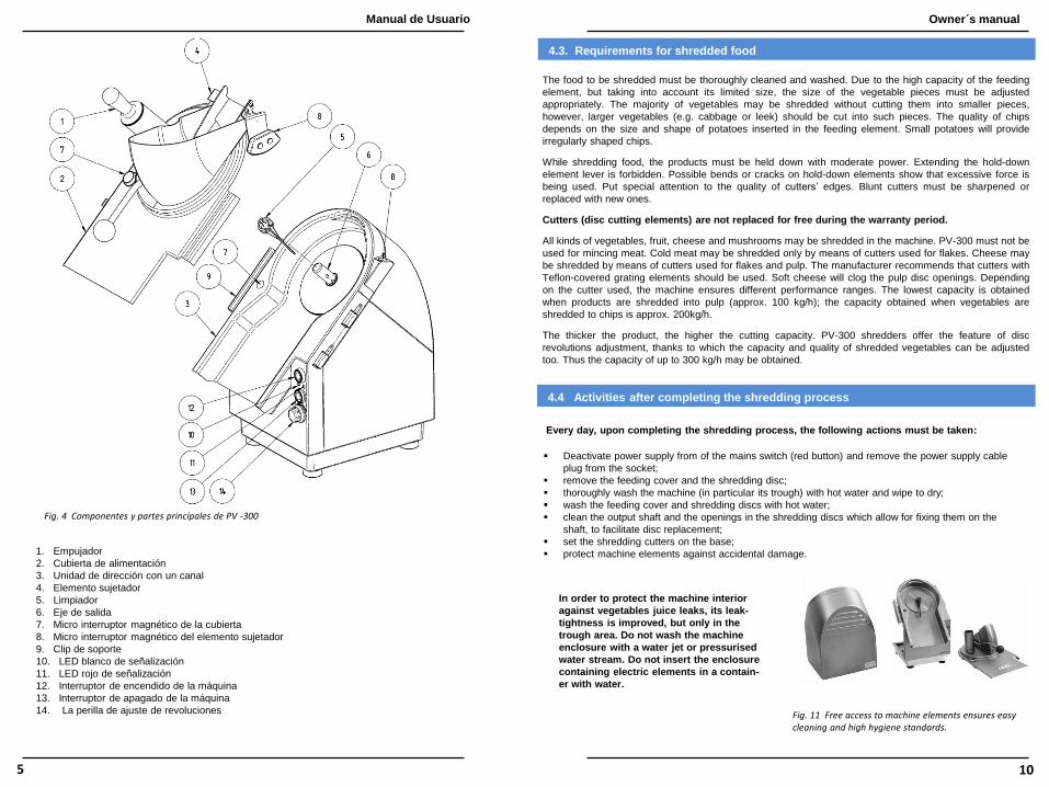
1. Pusher
2. Feeding cover
3. Drive unit with a trough
4. Hold-down element
5. Scraper
6. Output shaft
7. Cover magnetic micro switch
8. Hold-down element magnetic micro switch
9. Holding clip
10. White signaling LED
11. Red signaling LED
12. Machine power switch
13. Machine turnoff switch
14. Revolutions adjustment knob (for PV-300) with the scale controller settings
Fig. 4 Main components and parts of PV-300
4.3. Requerimientos para comida triturada
Los alimentos que serán triturados deben ser lavados por completo. Debido a la alta capacidad del
elemento de alimentación, pero tomando en cuenta su tamaño limitado, el tamaño de las piezas de
vegetales debe ser ajustada adecuadamente. La mayoría de los vegetales puede ser triturado sin cortarlos
en trozos pequeños, sin embargo, los vegetales más grandes (como el repollo y el poro) deben ser
cortados en trozos pequeños. La calidad del corte en barras o chips depende del tamaño y forma de las
papas que se pongan en el elemento de alimentación. Las papas pequeñas resultarán en barras de forma
irregular.
Mientras tritura alimentos, los productos deben ser sostenidos con fuerza moderada. No se debe extender
la palanca del elemento sujetador. Si observa grietas o dobleces en el elemento sujetador, significa que se
ha usado mucha fuerza. Ponga especial cuidado a la calidad de las orillas de los cortadores. Los
cortadores sin filo deben afilarse o remplazarse con cortadores nuevos.
El remplazo de los cortadores (elementos cortadores de los discos) sí tiene costo durante el
período de garantía.
Todos los tipos de vegetales, frutas, queso y hongos pueden triturarse en la máquina. El PV-300 no debe
usarse para moler carne. La carne fría puede triturarse solo con cortadores para hojuelas. El queso puede
triturarse con contadores para hojuelas o pulpa. El fabricante recomienda usar cortadores con elementos
de rallado que estén cubiertos en teflón. Los quesos suaves taparán las aperturas de los discos para
pulpa. Dependiendo del cortador que use, la máquina garantiza diferentes rangos de desempeño. La
capacidad más baja se obtiene cuando los productos se hacen pulpa (aprox. 100 kg/h); la capacidad
obtenida cuando los vegetales se hacen barras es de aprox. 200 kg/h. Entre más grueso sea el producto,
mayor será la capacidad de corte. El PV-300 ofrece la funcionalidad del ajuste de revoluciones del disco,
gracias a lo cual la capacidad y calidad de los vegetales triturados también se puede ajustar. De esta
forma, se puede obtener una capacidad de hasta 300 kg/h.
4.4. Acciones después usar el procesador de vegetales
Cada día, después de completar el proceso de triturado, debe realizar las siguientes acciones:
• Desactive la energía eléctrica presionando el botón rojo y desconecte el cable tomacorriente del
enchufe;
• remueva la cubierta de alimentación y el disco triturador;
• lave la máquina por completo (en especial el canal) con agua caliente y luego seque;
• lave la cubierta de alimentación y los trituradores con agua caliente.
• limpie el eje de salida y los resaques de los discos trituradores, lo que permite fijarlos al eje para
facilitar el remplazo de los discos;
• coloque los trituradores en la base; (no incluida)
• Proteja los elementos de la máquina contra daños accidentales.
Para proteger el interior de la máquina de
fugas del jugo de los vegetales o líquidos,
el área del canal es impermeable. No lave
la carcasa de la máquina con chorro de
agua o con un chorro de agua presurizada.
No coloque la carcasa la cual tenga
elementos eléctricos en un contenedor con
agua.
Fig. 11 Acceso libre a los elementos de la maquina para asegurar los altos estándares de higiene.
Owner´s manual Manual de Usuario
5 10
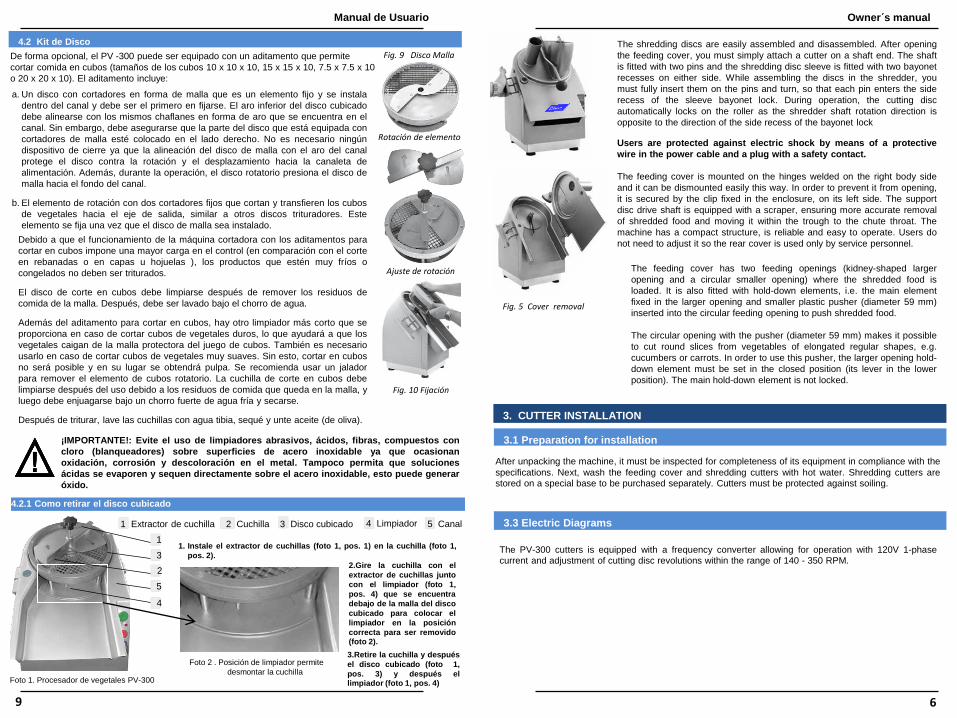
The shredding discs are easily assembled and disassembled. After opening
the feeding cover, you must simply attach a cutter on a shaft end. The shaft
is fitted with two pins and the shredding disc sleeve is fitted with two bayonet
recesses on either side. While assembling the discs in the shredder, you
must fully insert them on the pins and turn, so that each pin enters the side
recess of the sleeve bayonet lock. During operation, the cutting disc
automatically locks on the roller as the shredder shaft rotation direction is
opposite to the direction of the side recess of the bayonet lock
Users are protected against electric shock by means of a protective
wire in the power cable and a plug with a safety contact.
The feeding cover is mounted on the hinges welded on the right body side
and it can be dismounted easily this way. In order to prevent it from opening,
it is secured by the clip fixed in the enclosure, on its left side. The support
disc drive shaft is equipped with a scraper, ensuring more accurate removal
of shredded food and moving it within the trough to the chute throat. The
machine has a compact structure, is reliable and easy to operate. Users do
not need to adjust it so the rear cover is used only by service personnel.
The feeding cover has two feeding openings (kidney-shaped larger
opening and a circular smaller opening) where the shredded food is
loaded. It is also fitted with hold-down elements, i.e. the main element
fixed in the larger opening and smaller plastic pusher (diameter 59 mm)
inserted into the circular feeding opening to push shredded food.
The circular opening with the pusher (diameter 59 mm) makes it possible
to cut round slices from vegetables of elongated regular shapes, e.g.
cucumbers or carrots. In order to use this pusher, the larger opening hold-
down element must be set in the closed position (its lever in the lower
position). The main hold-down element is not locked.
Fig. 5 Cover removal
3. CUTTER INSTALLATION
3.1 Preparation for installation
3.3 Electric Diagrams
After unpacking the machine, it must be inspected for completeness of its equipment in compliance with the
specifications. Next, wash the feeding cover and shredding cutters with hot water. Shredding cutters are stored on a special base to be purchased separately. Cutters must be protected against soiling.
The PV-300 cutters is equipped with a frequency converter allowing for operation with 120V 1-phase current and adjustment of cutting disc revolutions within the range of 140 - 350 RPM.
4.2 Kit de Disco
De forma opcional, el PV -300 puede ser equipado con un aditamento que permite
cortar comida en cubos (tamaños de los cubos 10 x 10 x 10, 15 x 15 x 10, 7.5 x 7.5 x 10
o 20 x 20 x 10). El aditamento incluye:
a. Un disco con cortadores en forma de malla que es un elemento fijo y se instala
dentro del canal y debe ser el primero en fijarse. El aro inferior del disco cubicado
debe alinearse con los mismos chaflanes en forma de aro que se encuentra en el
canal. Sin embargo, debe asegurarse que la parte del disco que está equipada con
cortadores de malla esté colocado en el lado derecho. No es necesario ningún
dispositivo de cierre ya que la alineación del disco de malla con el aro del canal
protege el disco contra la rotación y el desplazamiento hacia la canaleta de
alimentación. Además, durante la operación, el disco rotatorio presiona el disco de
malla hacia el fondo del canal.
b. El elemento de rotación con dos cortadores fijos que cortan y transfieren los cubos
de vegetales hacia el eje de salida, similar a otros discos trituradores. Este
elemento se fija una vez que el disco de malla sea instalado.
Debido a que el funcionamiento de la máquina cortadora con los aditamentos para
cortar en cubos impone una mayor carga en el control (en comparación con el corte
en rebanadas o en capas u hojuelas ), los productos que estén muy fríos o
congelados no deben ser triturados.
El disco de corte en cubos debe limpiarse después de remover los residuos de
comida de la malla. Después, debe ser lavado bajo el chorro de agua.
Además del aditamento para cortar en cubos, hay otro limpiador más corto que se
proporciona en caso de cortar cubos de vegetales duros, lo que ayudará a que los
vegetales caigan de la malla protectora del juego de cubos. También es necesario
usarlo en caso de cortar cubos de vegetales muy suaves. Sin esto, cortar en cubos
no será posible y en su lugar se obtendrá pulpa. Se recomienda usar un jalador
para remover el elemento de cubos rotatorio. La cuchilla de corte en cubos debe
limpiarse después del uso debido a los residuos de comida que queda en la malla, y
luego debe enjuagarse bajo un chorro fuerte de agua fría y secarse.
Después de triturar, lave las cuchillas con agua tibia, sequé y unte aceite (de oliva).
4.2.1 Como retirar el disco cubicado
5 Canal 1 Extractor de cuchilla 2 Cuchilla 3 Disco cubicado 4 Limpiador
Foto 1. Procesador de vegetales PV-300
1
2
3
5
4
Foto 2 . Posición de limpiador permite
desmontar la cuchilla
3.Retire la cuchilla y después
el disco cubicado (foto 1,
pos. 3) y después el limpiador (foto 1, pos. 4)
1. Instale el extractor de cuchillas (foto 1, pos. 1) en la cuchilla (foto 1,
pos. 2).
Owner´s manual Manual de Usuario
9 6
Fig. 9 Disco Malla
Rotación de elemento
Ajuste de rotación
Fig. 10 Fijación
¡IMPORTANTE!: Evite el uso de limpiadores abrasivos, ácidos, fibras, compuestos con
cloro (blanqueadores) sobre superficies de acero inoxidable ya que ocasionan
oxidación, corrosión y descoloración en el metal. Tampoco permita que soluciones
ácidas se evaporen y sequen directamente sobre el acero inoxidable, esto puede generar
óxido.
2.Gire la cuchilla con el
extractor de cuchillas junto
con el limpiador (foto 1,
pos. 4) que se encuentra
debajo de la malla del disco
cubicado para colocar el
limpiador en la posición
correcta para ser removido (foto 2).

Fig. 6 Electric diagram of the vegetable cutter PV-300 (120V AC)
3.3 Conexión y prueba de funcionamiento
El PV -300 debe tener un voltaje de 1 x 120V con un conductor neutral y
protector térmico. Los cables eléctricos deben tener una sección media de
1.5 mm con fusibles con elementos 6A en cada fase. La instalación debe
terminarse con una clavija monofásica y el conductor protector debe estar
conectado al contacto marcado con un signo de tierra.
La instalación eléctrica debe ser revisada por personal autorizado para
protegerse contra una descarga eléctrica. La longitud del cable
tomacorriente de la máquina es de aproximadamente 2.5 m. El cable
termina con un enchufe de 3 pines. El enchufe debe estar localizado cerca
del equipo.
Fig. 7 Control de la dirección de
rotación
4. FUNCIONAMIENTO DEL PROCESADOR DE VEGETALES
4.1 La fijación de los discos de trituración y la caja de alimentación
Antes de remplazar los discos, la máquina debe desactivarse por medio del interruptor principal (botón rojo).
La lámpara de señalización se debe de apagar.
Después de abrir la cubierta, sostenga el disco triturador con ambas manos e insértelo dentro del eje para
que los rebajes del limpiador en la cubierta de montaje del disco estén alineados con los patas del eje.
Después de insertar el disco por completo, gírelo levemente a la izquierda. Para quitar los discos
trituradores, siga el procedimiento de arriba, pero de forma invertida. Durante el funcionamiento, el disco
cortador automáticamente se asegura en el eje ya que la dirección de rotación del eje del triturador es
opuesta a la dirección de los resaques laterales del seguro de la bayoneta del disco.
Para remover la cubierta de alimentación, desabroche el seguro del lado izquierdo de la máquina y quite la
cubierta de las bisagras del lado derecho de la máquina (con un movimiento hacia arriba, girando levemente
la cubierta a cualquier lado). Para colocar la cubierta de alimentación, siga el procedimiento de arriba, pero
de forma invertida (inserte la cubierta en las bisagras en la dirección opuesta en relación a su remoción).
Nota:
Una cubierta de alimentación correctamente fija y asegurada
activa el interruptor de emergencia, lo que permite que la
máquina se active con el interruptor de encendido (botón
verde). Sin embargo, el cortador no puede ser activado si la
cubierta de alimentación no está cerrada con el elemento
sujetador (antes de eso, la lámpara de señalización debe
indicar el estado de activación de la máquina).
Fig. 8 La fijación del disco en el eje
Resaque en del disco
Perno de la flecha
Owner´s manual Manual de Usuario
7 8

3.3 Connection to mains and test run
PV-300 must be supplied with 1x120 Vac voltage with a protective and neutral
conductor. The supply cables must have 1.5 mm2 cross-section with fuses of
6A fuse-element in each phases. The installation must be terminated with a
phase socket and the protective conductor must be connected to the contact
marked with the earthing sign.
The power supply installation must be inspected by authorized personnel for
protection against electric shock. The length of the machine power cable is
approx. 2.5 m. The cable is terminated with a 3-pin plug. The plug-in socket
must be located in the vicinity of the machine location.
Fig. 7 Checking the direction of rotation
4. CUTTER OPERATION
4.1. Fixing shredding discs and the feeding box
Before replacing discs, the machine must be deactivated by the main switch (red button). The signaling
lamp comes off.
After opening the cover, hold the shredding disc with two hands and insert it into the shaft, so that the
bayonet recesses on the disc mounting sleeve will align with the pins on the shaft. After fully inserting the
disc, turn it slightly to the left. In order to remove a shredding disc, follow the above procedure in the
reverse order. During operation, the cutting disc automatically locks on the roller as the shredder shaft
rotation direction is opposite to the direction of the side recess of the bayonet lock
In order to remove the feeding cover, unfasten the clip on the left side of the machine and remove the
cover from the hinges located on the right side of the machine (upward plane motion; slightly turn the
cover to either side).
Fig. 8 Fixing the discs on the shaft
Nota:
In order to fix the feeding cover, follow the above
procedure in a reverse order (insert the cover into the
hinges in the opposite direction in relation to its removal).
A correctly fixed and clipped feeding cover activates the
emergency switch allowing for the machine activation by
mean the mains switch (green button). However, the
cutter may be activated not before the feeding opening is
closed by means the hold-down element (before that, the
signaling lamp must indicate the machine activation
status).
Fig. 6 Diagrama Eléctrico del procesador de vegetales PV-300 (120V AC)
Owner´s manual Manual de Usuario
7 8

4.2 Cube set (Fig. 9)
As an option, PV-300 may be equipped with an attachment making it possible to dice
food (dice dimensions 10 x 10 x 10, 15 x 15 x 10, 7.5 x 7.5 x 10 or 20 x 20 x 10).
The attachment includes:
a. Disc with cutters in a form of a mesh being a fixed element installed on the ring
located inside the trough. This disc is fixed as the first element. The lower mesh
disc ring must be aligned by means of the chamfers with the same chamfers as in
the ring located in the trough. However, attention must be paid that the part of the
disc equipped with mesh cutters is located on its right side . No locking device for
the disc is necessary as the alignment of the mesh disc with the trough ring
protects the disc against rotation and sliding into the feeding throat. Moreover,
during the machine operation, the rotating disc presses the mesh disc to the
trough bottom.
b. The rotating element with two fixed cutters which cut off and transfer diced
vegetables is fixed on the output shaft, similar other shred- ding discs. This
element is fixed after the mesh disc is installed.
Due to the fact that operation of the cutting machine with the dicing attachment
imposes the highest load on the drive (in comparison with slicing or cutting into
chips or flakes), frozen or intensively chilled products should not be shredded.
The dicing disc must be cleaned after food residues have been removed from the
mesh. Next, it must be water jet rinsed and dried.
Together with the cube attachement there is another shorter scraper, Provided in
case of dicing vegetables in hard state, it will help the vegatables from to fall the
mesh shield of the cube set, also in case of dicing vegetables in softened state it is
necessary to use it. Without it the cube cutting is impossible, and instead of
vegetable dice we got the pulp.
It is recommended to use the puller to remove the rotating cube element. The
dicing blade should be cleaned after pushed food remains on the grid, and then
rinse under a strong stream of cool water and dry.
After shredding, wash the blade in warm water, wipe dry and rub olive.
4.2.1 Removal of the cube set after use, when the scraper was used
5 trough 1 blade puller 2 blade 3 cube disc 4 scrapper
1. Install the blade puller (photo 1, pos. 1) on a blade (photo 1, pos. 2).
Photo 1. Vegetable cutter PV-300
Photo 2 . Scrapper position which allows
the demounting of the blade
3.Take off the blade and after
that take off the cube set
(photo 1, pos. 3), and the scrapper (photo 1, pos. 4).
Los discos trituradores se ensamblan y desensamblan fácilmente.
Después de abrir la cubierta de alimentación, simplemente debe añadir
un cortador al final del eje. El eje está equipado con dos pernos y la
cubierta del disco triturador tiene dos resaques (muescas) en el
limpiador al costado. Al ensamblar los discos en el triturador, debe
insertarlos completamente en los pernos y girarlos para que cada perno
entre en los rebajes laterales del seguro de limpiador de la cubierta.
Durante el funcionamiento, el disco cortador automáticamente se
asegura en el eje o flecha ya que la dirección de rotación del eje del
procesador es opuesta a la dirección de los rebajes laterales del
limpiador-
Los usuarios son protegidos de una descarga eléctrica con un
cable de seguridad en el cable tomacorriente y un enchufe de
seguridad.
La cubierta de alimentación está montada en bisagras soldadas en el
lado derecho del cuerpo y puede ser fácilmente desmontada. Para evitar
que se abra, está asegurada con un clip fijo en la cerradura, del lado
izquierdo. El eje del disco de soporte está equipado con un limpiador, lo
que asegura la eliminación precisa de la comida triturada y moviéndola
dentro del canal a la canaleta. La máquina tiene una estructura
compacta que es confiable y fácil de operar. Los usuarios no necesitan
ajustarla, por lo que la cubierta trasera solo la usa el personal de
mantenimiento.
La cubierta de alimentación tiene dos aperturas de alimentación (una
apertura grande con forma de «riñon» y una apertura más pequeña con
forma circular), donde se carga la comida triturada. También está
equipado con elementos sujetadores, por ejemplo, el elemento principal
fijo en la apertura más grande y el empujador de plástico
Fig. 5 Extracción de Tapa
(diámetro 59 mm) que está insertada en la apertura de alimentación circular para empujar la
comida triturada. La apertura circular con el empujador (diámetro 59 mm) hace posible cortar
rebanadas redondas de vegetales largos de forma regular, por ejemplo, pepinos o zanahorias. Para
poder usar el empujador, el elemento sujetador de la apertura más grande debe estar colocado en
posición cerrada (y la palanca en la posición inferior). El elemento sujetador principal no está
cerrado.
3. INSTALACIÓN DEL PROCESADOR DE VEGETALES
3.1 Preparación para la instalación
Después de desempacar la máquina, debe revisar que el equipo esté completo y que cumpla con las
especificaciones. Después, lave la cubierta de alimentación y los trituradores con agua caliente. Los
trituradores se guardan en una base especial que se vende por separado. Los cortadores deben
protegerse contra la suciedad.
3.2 Diagrama Eléctrico
Los trituradores de la serie PV-300 pueden variar, principalmente en los accesorios eléctricos. Los
cortadores PV -300 están equipados con un convertidor de frecuencia que permite el funcionamiento
con corriente monofásica 120V y con ajuste de las revoluciones de discos para cortar dentro del rango
de 140 - 350 RPM.
Owner´s manual Manual de Usuario
9 6
Fig. 9 Cube set.
Fig .10 Fixing the cube set with puller
Rotation adjustment to cube set with puller
IMPORTANT!: Avoid use of abrasive cleaners, acid, fibers, chlorides (such as
chlorine bleach), on stainless steel surfaces will cause pitting, corrosion, and metal
discoloration. Allowing salty solutions to evaporate and dry on stainless steel may
also contribute to corrosive conditions. Do not submerge the entire unit into water.
2. Turn the blade by a blade
puller together with the
scrapper (photo 1, pos. 4)
which is behind the net of the
cube, so that the scraper is in
the correct position for re- moval (photo 2).
1
2
3
5
4
4.3. Requirements for shredded food
The food to be shredded must be thoroughly cleaned and washed. Due to the high capacity of the feeding
element, but taking into account its limited size, the size of the vegetable pieces must be adjusted
appropriately. The majority of vegetables may be shredded without cutting them into smaller pieces,
however, larger vegetables (e.g. cabbage or leek) should be cut into such pieces. The quality of chips
depends on the size and shape of potatoes inserted in the feeding element. Small potatoes will provide
irregularly shaped chips.
While shredding food, the products must be held down with moderate power. Extending the hold-down
element lever is forbidden. Possible bends or cracks on hold-down elements show that excessive force is
being used. Put special attention to the quality of cutters’ edges. Blunt cutters must be sharpened or
replaced with new ones.
Cutters (disc cutting elements) are not replaced for free during the warranty period.
All kinds of vegetables, fruit, cheese and mushrooms may be shredded in the machine. PV-300 must not be
used for mincing meat. Cold meat may be shredded only by means of cutters used for flakes. Cheese may
be shredded by means of cutters used for flakes and pulp. The manufacturer recommends that cutters with
Teflon-covered grating elements should be used. Soft cheese will clog the pulp disc openings. Depending
on the cutter used, the machine ensures different performance ranges. The lowest capacity is obtained
when products are shredded into pulp (approx. 100 kg/h); the capacity obtained when vegetables are
shredded to chips is approx. 200kg/h.
The thicker the product, the higher the cutting capacity. PV-300 shredders offer the feature of disc
revolutions adjustment, thanks to which the capacity and quality of shredded vegetables can be adjusted
too. Thus the capacity of up to 300 kg/h may be obtained.
4.4 Activities after completing the shredding process
Every day, upon completing the shredding process, the following actions must be taken:
Deactivate power supply from of the mains switch (red button) and remove the power supply cable
plug from the socket;
remove the feeding cover and the shredding disc;
thoroughly wash the machine (in particular its trough) with hot water and wipe to dry;
wash the feeding cover and shredding discs with hot water;
clean the output shaft and the openings in the shredding discs which allow for fixing them on the
shaft, to facilitate disc replacement;
set the shredding cutters on the base;
protect machine elements against accidental damage.
Fig. 11 Free access to machine elements ensures easy cleaning and high hygiene standards.
In order to protect the machine interior
against vegetables juice leaks, its leak-
tightness is improved, but only in the
trough area. Do not wash the machine
enclosure with a water jet or pressurised
water stream. Do not insert the enclosure
containing electric elements in a contain-
er with water.
1. Empujador
2. Cubierta de alimentación
3. Unidad de dirección con un canal
4. Elemento sujetador
5. Limpiador
6. Eje de salida
7. Micro interruptor magnético de la cubierta
8. Micro interruptor magnético del elemento sujetador
9. Clip de soporte
10. LED blanco de señalización
11. LED rojo de señalización
12. Interruptor de encendido de la máquina
13. Interruptor de apagado de la máquina
14. La perilla de ajuste de revoluciones
Fig. 4 Componentes y partes principales de PV -300
Owner´s manual Manual de Usuario
5 10
4.5 Periodical maintenance
At least once a year, the cutter must undergo a periodical maintenance process.
The following actions must be taken:
check the condition of the worm reducer; in case any abnormal noise is detected during its operation, this
element must be replaced;
check the condition of the plastic carrier on the output shaft; replace it if cracks are observed,
check the play on output shaft bearings;
clean the enclosure interior paying special attention on the electric installation condition.
In case technical faults are detected, transfer the machine to a repair workshop.
In the case of a longer standstill, periodical maintenance must be carried out. Next, the machine must be
packed in a carton box, secured against toppling to a side and stored in a dry room (temperature 10 – 18°C).
4.6. Methods of fixing operating faults
Motor does not work
No voltage in the mains or no phase. Check voltage.
Improperly fixed feeding cover. Fix correctly.
Machine overheated. Wait a few minutes.
Electric installation damage. Inspect and repair.
Damaged motor. Repair or replace.
Operation is too noisy Damaged output shaft bearings. Disassembly the unit and replace bearings.
Faulty shredding Blunt or damaged shredding cutters. Sharpen or replace.
See below for the error codes indicated by red and white LEDs for the regulated controller in PV-300
Correct operation The red LED is off. The white LED is on.
Interrupted motor operation due
to voltage interruption
The red LED blinks rapidly. The
white LED is off.
Error reported by the inverter The red LED blinks in long intervals. The white LED is off.
Lack of simultaneous Hall sensors
operation in the group
The red LED blinks in long intervals. The
white LED is off.
Motor thermal protection error
(70°C, hysteresis 15°C)
The red LED is permanently on. The
white LED is off.
After indication of any fault, the motor is stopped and may be restarted after the fault is repaired and the
GREEN button (START) is pressed.
Discos de barra
K-10 barras10 x 10 x 10 mm
K-15 barras15 x 15 x 10 mm
K-7.5 barras 7.5 x 7.5 x 10 mm
Base de soporte de disco (para 6 discos
Tipos de cuchillas:
• Cuchilla para pulpa
• Cuchillas para rebanadas reguladas de 0 a 5mm con regulación de 0.5m
• Cuchilla para hojuelas – tamaños 3.5mm y 5.5mm
• Cuchillas para rebanadas onduladas - rebanadas con grosor de 2.5mm a 5.5mm.
Nota: Todos los tipos disco de corte y disco de barra deben solicitar por separado
Fig. 2 Discos de trituración
2.4 Descripción del diseño de la maquina.
El diseño de la máquina es modular, incluyendo: la unidad de mando (con un canal y la unidad de
cubierta, incluyendo los elementos de alimentación) y discos cortadores reemplazables.
Todos los elementos externos de la unidad de mando y las partes que entran en contacto directo con la
comida triturada están fabricados en acero y son resistentes al ácido. Los discos de soporte de los
trituradores, los cortadores, los ralladores y las cubiertas para montar los discos están hechos de acero
inoxidable. Esto facilita el mantenimiento y mejora la apariencia estética del producto.
La unidad de mando del PV-300 tiene una forma de un cuerpo con un canal para vegetales rebanados
y la unidad de cubierta con elementos de alimentación. La unidad de mando está colocada sobre cuatro
patas ajustables a la superficie de la mesa
Fiig. 3 Activación del equipo
La unidad de mando, que se activa con un engrane helicoidal
integrado, está equipado con dispositivos de apagado de
seguridad que hacen que sea imposible activarlo cuando la
cubierta está abierta, ha sido removida o cuando el elemento
sujetador está abierto. Mientras tritura, cuando el elemento
sujetador está abierto para llenar la máquina con alimentos, la
máquina se apaga automáticamente sin activar el interruptor
encendido (botón verde). Durante el funcionamiento del elemento
sujetador, la lámpara se enciende. Después de abrir la cubierta
para remplazar los discos o para limpiar el canal, el interruptor de
encendido (botón verde) debe activarse de nuevo ya que el
interruptor de emergencia que se encuentra en la tapa corta la
energía que va al motor y la lámpara se apaga.
Los elementos cortadores internos y externos (principalmente el
canal y la cubierta con elementos de alimentación) son fabricados
durante el proceso de estampado de la hoja metálica y tienen
dobleces lisos (radio R=3), lo cual hace que la limpieza de la
máquina sea más sencilla. La gran capacidad del elemento de
alimentación hace posible triturar productos enteros.
Owner´s manual Manual de Usuario
11 4

Note:
All repairs must be carried out after disconnecting the
power supply cable plug. After completing repairs, the
rear cover must be always fixed in its place
Fig. 12 Removal and fixing the rear cover in order to repair operating faults.
5. SPARE PARTS CATALOGUE
While ordering spare parts and components of PV -300 vegetable cutters, the following data must be
provided:
1. Machine type and year of manufacture
2. Machine factory number
3. Part or component number
4. Part or component name and required quantity
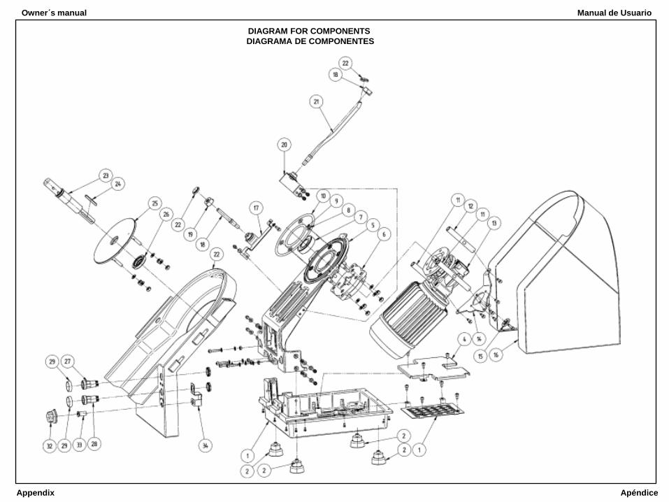
Note:
Part item numbers are compatible with the numbers provided on the machine diagram.
Item no. Part no. Element name
1 6011 Lower base element
2 4011 Foot
3 6012 Lower guard
4 6013 Electronic controller mounting plate
5 6020 Upper base element - set
6 6014 Spacing sleeve
7 6206-2rsr Bearing
8 11.3 x 2.4 O-ring
9 79.2 x 5.7 O-ring
10 159.2 x 5.7 O-ring
11 6015 Long gear-motor support
12 6016 Short gear-motor support
13 M045 FC R 10 C O Q D B3 Gear-motor
14 6017 Mounting plate
15 6008 Retaining plate
16 6040 Rear guard - set
17 6105 Cover sensor tube support - set
18 6110 Cover sensor tube - set
19 6116 Support sleeve nut
20 6120 Hold-down element sensor tube support - set
21 6125 Hold-down element sensor tube - set
22 6025_br Body - set (NA)
6025_zr Body - set (for PV -300)
23 6006 Output shaft - set
2. CARACTERÍSTICAS TÉCNICAS
2.1 Ámbito de Aplicación
El PV-300 puede ser usado para cortar todo tipo de frutas y vegetales crudos en rebanadas, chips,
hojuelas y pulpa o, sí se usa un aditamento, para cortar en cubos y rallar queso. El PV -300 puede
usarse en establecimientos de servicios alimenticios y plantas procesadoras de alimentos. El rango de
aplicación incluye establecimientos de servicios alimenticios, por ejemplo, jardines de niños, escuelas,
hospitales, unidades militares y otros establecimientos como hoteles, cantinas, restaurantes, pizzerías,
barras de comida rápida, barras de ensaladas y pequeñas plantas procesadoras de frutas y vegetales.
Principalmente elimina el esfuerzo requerido para triturar frutas y vegetales de forma manual y asegura
ahorros en el costo ya que el tiempo de preparación de los alimentos disminuye.
2.2 Información Técnica
Dimensiones:
Longitud 463 mm
Ancho 366 mm
Altura 648 mm
Peso 28 kg
Revoluciones del
cortador aprox. 140 - 350 RPM
(De acuerdo con la dirección indicada por la flecha en la cubierta de alimentación)
Poder del motor 0.75 kW
Tensión de red 1 x 115V
Capacidad 150 - 300 kg/h
Discos trituradores De acuerdo a las preferencias del cliente. El juego sugerido de inicio para 4 discos
incluye cortadores para rebanadas, hojuelas y pulpa.
2.3 Tipos de discos trituradores (Fig. 2)
Juego de discos para rebanar (2 cortadores)
P-1.5 rebanadas 1.5 mm
P-2.5 rebanadas 2.5 mm
P-3.5 rebanadas 3.5 mm
P-4.5 rebanadas 4.5 mm
P-5.5 rebanadas 5.5 mm
Juego de discos para chips
F-6 chips delgadas 6 x 6 mm
F-6 chips medianas 8 x 8 mm
F-10 chips estándar 10 x 10 mm
F-10 chips gruesas 12 x 10 mm
S-2 palitos estándar 2 x 23 mm
S-3 palitosestándar 3 x 3 mm
Juego de discos para pulpa Cortadores de hojuelas
W-2 Hojuelas finas 2 mm
W-2.5 Hojuelas medianas 2.5 mm
W-3 Hojuelas gruesas 3 mm
W-7 Hojuelas muy gruesas 0.7 mm
Owner´s manual Manual de Usuario
3 12
Item no. Part no. Element name
24 6 x 6 x 50 Prismatic key
25 6035 Bearing plate - set
26 30 x 50 x 10 Simmer ring
27 FT22-Z Mains switch (green button)
28 FT22-C Mains switch (red button)
29 4019 Decorative ring
30 LED 5 R-LC Red LED with a holder, RTP-50HB-chrome
31 LED 5 R-LB White LED with a holder, RTP-50HB-chrome
32 6003 Revolutions adjustment knob (for PV-300)
33 6009 Cable bush (for PV-300)
34 6136 Potentiometer support (for PV -300)
35 4W-2K5 Potentiometer (revolutions adjustment knob for PV-300
36 SMG-SS2 Electronic controller (NA)
SMG-SRS2 Electronic controller (PV -300)
37 AFC-160 Frequency converter (PV-300)
38 KTY81-210 Temperature sensor
39 A 1104 EUA HALL sensor
40 6050 Cover - set
41 6080 Cover magnet holder - set
42 6081 Cover magnet holder shield
43 6079 Knob - set
44 6065 Hold-down element - set
45 6089 Hold-down element magnet holder support
46 6085 Hold-down element magnet holder - set
47 6088 Hole plugs
48 6046 Hold-down element shaft
49 6047 Mushroom-shaped nut
50 6150 Shredding disc for fine flakes (2 mm)
51 6151 Grating element for fine flakes (2 mm)
52 6151 Support disc (for flakes or pulp)
53 6152 Mounting sleeve
54 6155 Shredding disc for medium flakes (2.5 mm)
55 6156 Grating element for medium flakes (2.5 mm)
56 6160 Shredding disc for thick flakes (3 mm)
57 6161 Grating element for thick flakes (3 mm)
58 6165 Shredding disc for very thick flakes (7 mm)
59 6166 Grating element for very thick flakes (7 mm)
60 6170 Shredding disc for pulp
61 6171 Grating element for pulp
62 6175 Slicing disc - slice thickness 1.5 mm (P-1.5)
63 6176 Slicing support disc
64 6177 Set of two cutters for the slicing disc
65 6180 Slicing disc - slice thickness 2.5 mm (P-2.5)
66 6185 Slicing disc - slice thickness 3.5 mm (P-3.5)
67 6190 Slicing disc - slice thickness 4.5 mm (P-4.5)
68 6195 Slicing disc - slice thickness 5.5 mm (P-5.5)
69 6200 Disc for cutting food in 3 x 3 mm bars (S-3)
70 6201 Support disc for cutting food in bars
71 6205 Disc for cutting food into 6 x 6 mm thin chips (F-6)
72 6206 Support disc for cutting food into chips
73 6207 Cut-off cutter for chips
74 6208 Cutter segment for chips
1. INTRODUCCIÓN
1.1 El procesador de vegetales PV -300 es una máquina culinarias que cumplen con los estándares
aplicables con respecto a higiene y seguridad.
1.2 El cortador de vegetales debe estar conectado a un enchufe con conexión a tierra (ver 3.3).
1.3. Al seguir las directrices indicadas en el Manual y operando la máquina de una manera compatible
con su rango de uso, asegurará un funcionamiento seguro y prolongado.
1.4. El fabricante no se hace responsable por cualquier consecuencia resultante del uso de la
máquina en una manera incompatible con este Manual.
1.5. El procesador de vegetales PV -300 está disponible en suministro de energía en corriente
monofásica de 120V/60Hz con ajuste de revoluciones.
1.6. El fabricante recomienda comprar un juego 4 discos de corte para el PV-300. El usuario puede
comprar los diferentes tipos de discos cortadores y un juego de corte en cubos como función adicional
que no requiere más modificaciones.
1.7. El nivel de ruido en la estación operando el equipo en condiciones de uso normal (altura de 1.6 m,
distancia de la máquina de -1m.) no debe exceder 70dB.
1.8. Para el PV-300 con ajuste de revoluciones, el fabricante recomienda ajustar la perilla de acuerdo
con la "Tabla de configuración óptima", adjunta al final de este manual (Nota 2)
FIG.1. VISTA GENERAL DEL CORTADOR DE VEGETALES PV- 300
CORTADOR DE VEGETALES PV- 300
Owner´s manual Manual de Usuario
13 2

Item no. Part no. Element name
75 6210 Disc for cutting food into 8 x 10 mm medium chips (F-8)
76 6215 Disc for cutting food into 10 x 10 mm standard chips ( F-10 )
77 6220 Disc for cutting food into 12 x 10 mm thick chips (F-12)
78 6230 Dicing set - 10 x 10 x 10 mm dice (K-15)
79 6235 Mesh disc for dicing 10 x 10 mm
80 6240 Dicing set - 15 x 15 x 10 mm dice (K-10)
81 6245 Mesh disc for dicing 15 x 15 mm
82 6250 Dicing set - 7.5 x 7.5 x 10 mm dice (K-7.5)
83 6255 Mesh disc for dicing 7.5 x 7.5 mm
84 6260 Rotating element of the dicing set for discs - item 73 - 76
85 6261 Dice cut-off cutter
86 6263 Mounting sleeve
Note 1:
Note 2:
While shredding potatoes into chips, a few per cent of the product mass may be discarded (up to 20 %) in
a form of small pieces or irregular strips. The quality of shredding to obtain depends on potatoes size, their
shape and quality. The discarded material may be used for different purposes, e.g. to mash it into pulp in
order to produce potato cakes.
Table of optimal settings of regulator knob
Cutting type Control knob position Product type
Product French
Frites/Bars Slices Pulp Chips Cube 1 1.5 2 2.5 3 3.5 4 4.5 5 Pole Hole
Cucumber x x x
Carrot x x x
Carrot x x x x
Potato x x x x
Potato x x x
Potato x x x
Celery / Jicama x1 x x
Celery2 / Jicama2 x x x
Celery / Jicama x3 x x
Tomato x x x
Tomato x x x
Onion x x x
Onion x x x
1 Chips “7” 2 Celery cut in cubes only after softening 3 Raw selery / Raw Jicama can be cut in cubes throwing to the throat the single pieces
CONTENIDO
1. INTRODUCCIÓN……………………………………………………………………………….……………..2
2. CARACTERÍSTICAS TÉCNICAS………………………………………………………….………………..3
2.1 Ámbito de aplicación
2.2 Información técnica
2.3 Tipos de discos trituradores
2.4 Descripción del diseño de la máquina
3. INSTALACIÓN DEL PROCESADOR DE VEGETALES.………………………………….…………….6
3.1 Prepararse para la instalación
3.2 Diagrama eléctrico
3.3 Conexión y prueba de funcionamiento
4. FUNCIONAMIENTO DEL PROCESARO DE VEGETALES.………….…………………………..…....8
4.1 Arreglar los discos trituradores y la caja de alimentación
4.2 Juego de corte en cubos
4.2.1. Cómo retirar el disco cubicado
4.3 Requerimientos para comida triturada
4.4 Actividades después de usar el procesador de vegetales
4.5 Mantenimiento periódico
4.6 Métodos para reparar fallas de funcionamiento
5. CATALOGO DE REFACCIONES………………………………………………….……………………..12
NOTA
En el procesador de vegetales PV -300 con control de velocidad, para obtener la mejor calidad,
desempeño y funcionamiento al cortar, la velocidad tiene que ser ajustada al tipo de cuchilla de corte y
al tipo de producto a cortar, aplicando la regla:
Corte pesado (como vegetales en cubos, papas a la francesa) revoluciones lentas
Cortes delgados (como chips y pulpa) revoluciones más rápidas.
Owner´s manual Manual de Usuario
1 14
Esta unidad no se puede usar por personas (incluidos niños) con
discapacidades físicas, sensoriales o mentales, o la falta de experiencia y
conocimiento, a menos que hayan recibido supervisión o instrucción
previamente. Los niños, aún bajo supervisión, no deben jugar con el equipo.
Nunca dé servicio, limpieza o mantenimiento a esta unidad mientras esté
conectada a la energía eléctrica.
Mantenga siempre bien cerrada la tapa al estar trabajando, revise que el
broche o perno de la tapa esté bien cerrado.
Apague el equipo cuando no este en uso. Se recomienda usar el equipo por
periodos de 20 min por 30 min sin operar antes de usarlo nuevamente.
¡Peligro! Nunca introduzca sus manos o dedos dentro de la tapa donde giran
los rodillos porque pueden ser mutilados.
Owner´s manual
Appendix
Manual de Usuario
Apéndice
DIAGRAM FOR COMPONENTS
DIAGRAMA DE COMPONENTES