operating instructions for electronic temperature … · tdd tdd k04/0309 page 3 2. note please...
TRANSCRIPT

Operating Instructions
for
Electronic Temperature Switch
Model: TDD

TDD
page 2 TDD K04/0309
1. Contents
1. Contents ........................................................................................................ 2 2. Note .............................................................................................................. 3 3. Instrument Inspection .................................................................................... 3 4. Regulation Use .............................................................................................. 3 5. Operating Principle ........................................................................................ 4 6. Mechanical Connection ................................................................................. 4 7. Electrical Connection .................................................................................... 5
7.1. Connector pin assignment TDD-153, TDD-353 ................................... 5 7.2. Connector pin assignment TDD-553, TDD-753 ................................... 6
8. Commissioning .............................................................................................. 7 8.1. Button function ..................................................................................... 7
9. Adjustments .................................................................................................. 8 9.1. Value setting ........................................................................................ 8
10. Set- up Mode ................................................................................................ 9 10.1. Adjustments for TDD-1... and TDD-3... ................................................ 9 10.2. Adjustments for TDD-5...; TDD-7... .................................................... 10
11. Main Menu Options ..................................................................................... 12 11.1. Switching point ................................................................................... 12 11.2. Hysteresis .......................................................................................... 12 11.3. Window point (Double Point), (only for TDD-1… and TDD-3…) ........ 12 11.4. Switching behaviour ........................................................................... 13 11.5. Filter (only for TDD-1… and TDD-3…)............................................... 14 11.6. Transient response (only for TDD-5… and TDD-7…) ........................ 14 11.7. Contact model .................................................................................... 15 11.8. Change Code ..................................................................................... 15
12. Maintenance ............................................................................................... 15
Manufactured and sold by:
Kobold Messring GmbH Nordring 22-24
D-65719 Hofheim Tel.: +49(0)6192-2990 Fax: +49(0)6192-23398
E-Mail: [email protected] Internet: www.kobold.com

TDD
TDD K04/0309 page 3
2. Note
Please read these operating instructions before unpacking and putting the unit into operation. Follow the instructions precisely as described herein. The devices are only to be used, maintained and serviced by persons familiar with these operating instructions and in accordance with local regulations applying to Health & Safety and prevention of accidents. When used in machines, the measuring unit should be used only when the machines fulfil the EWG-machine guidelines.
3. Instrument Inspection
Instruments are inspected before shipping and sent out in perfect condition. Should damage to a device be visible, we recommend a thorough inspection of the delivery packaging. In case of damage, please inform your parcel service / forwarding agent immediately, since they are responsible for damages during transit. Scope of delivery: The standard delivery includes: • Electronic Temperature Switch model: TDD • Operating Instructions
4. Regulation Use
Any use of the Electronic Temperature Switch, model: TDD, which exceeds the manufacturer’s specification may invalidate its warranty. Therefore any resulting damage is not the responsibility of the manufacturer. The user assumes all risk for such usage.

TDD
page 4 TDD K04/0309
5. Operating Principle
The KOBOLD Model TDD temperature sensor is used for economical measuring and monitoring of temperature. It can be used for any application in which temperatures must be monitored with great accuracy. The sensor element is a semiconductor that outputs a digital signal to the electronic processor in 0,5 °C steps. The measured values are shown on a 3-digit LED display. The switch setpoint can be adjusted as required within the measuring range.
6. Mechanical Connection
Before installation: • Please check, if the switching temperature and switching function of TDD
device is in agreement with your system requirements (specifications). • Ensure that the maximum operating pressure or temperature for the device is
not exceeded. Installation:
or a flat gasket to seal the threaded connections. • The mounting position should be selected so that the sensor tip is always
immersed in the liquid being monitored, thus ensuring optimal heat exchange between the liquid and the temperature sensor.
• Note that deposits that build up on the sensor tip or dirty liquids can have an insulating effect and cause invalid measurements.
• Whenever possible, after the mechanical installation is complete, the joint at the threaded connector and the supply piping should be checked to ensure that it is tight and does not leak.
• This device is installed in a matching sleeve. Use sealing tape (i.e. PTFE tape)

TDD
TDD K04/0309 page 5
7. Electrical Connection
Attention! Make sure that the supply voltage of your system correspond with the voltage of the measuring unit specified on the nameplate.
• Make sure that the electrical supply lines are de-energised. • Make the connection using the M 12x1 connector socket, as shown in the
accompanying diagram. • Appropriate connectors with different cable lengths are optionally available.
Attention! Incorrect wiring will lead to damage of the unit’s electronics.
7.1. Connector pin assignment TDD-153, TDD-353
Option: plug with cable ZUB-KAB-12K002 Plug
TDD
page 6 TDD K04/0309
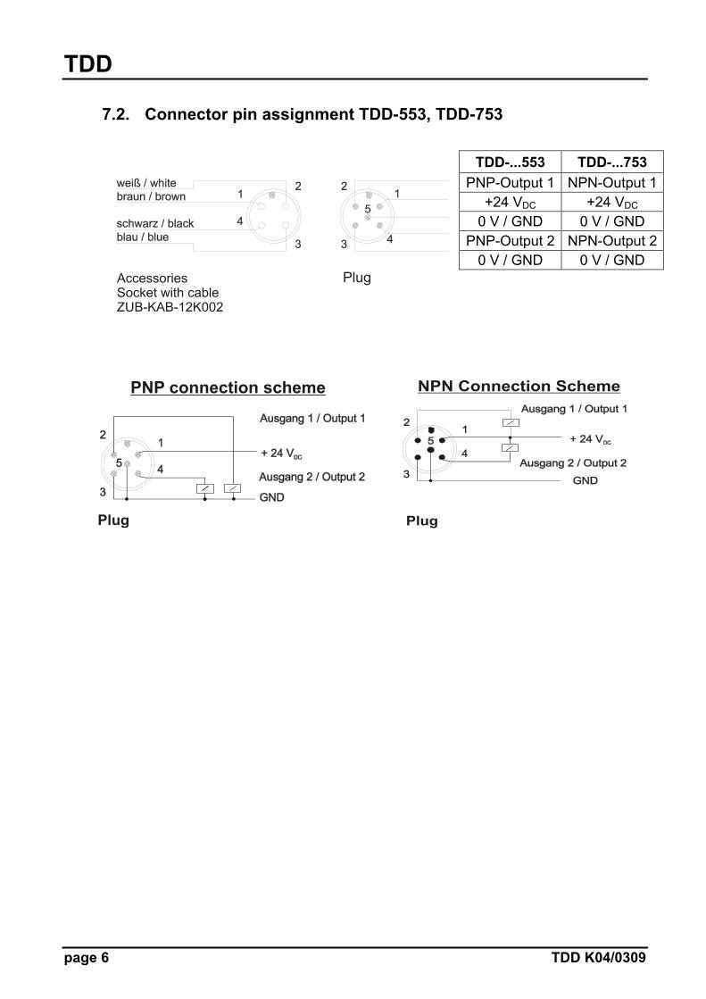
7.2. Connector pin assignment TDD-553, TDD-753
TDD-...553 TDD-...753 PNP-Output 1 NPN-Output 1
+24 VDC +24 VDC 0 V / GND 0 V / GND
PNP-Output 2 NPN-Output 20 V / GND 0 V / GND
Plug
PNP connection scheme
Plug
NPN Connection Scheme
Plug
TDD
TDD K04/0309 page 7
3 sec
Normal Mode
Anytime:
or 20 secDon’t press any key
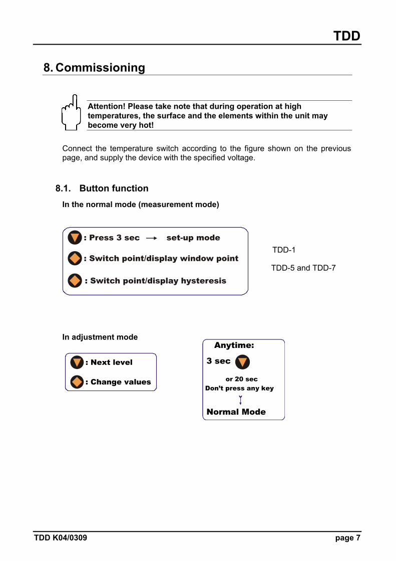
8. Commissioning
Attention! Please take note that during operation at high temperatures, the surface and the elements within the unit may become very hot!
Connect the temperature switch according to the figure shown on the previous page, and supply the device with the specified voltage.
8.1. Button function In the normal mode (measurement mode)
: Press 3 sec set-up mode
: Switch point/display window point
: Switch point/display hysteresis
In adjustment mode
: Next level
: Change values
TDD-1
TDD-5 and TDD-7
TDD
page 8 TDD K04/0309
9. Adjustments
The following values can be changed at the temperature transmitter:
Display range Factory pre-set Switching point (SPo, set-point) -199...999 50.0 Hysteresis (HYS) -199...0 000 Window point (double) Switching point ...999 --- (inactive) Filter (Filt) 1/2/4/8/16/32/64 1 Contact-Type (Con) Contact (N/O) or (N/C) N/O Contact Code (CCo, change code) 000...999 000
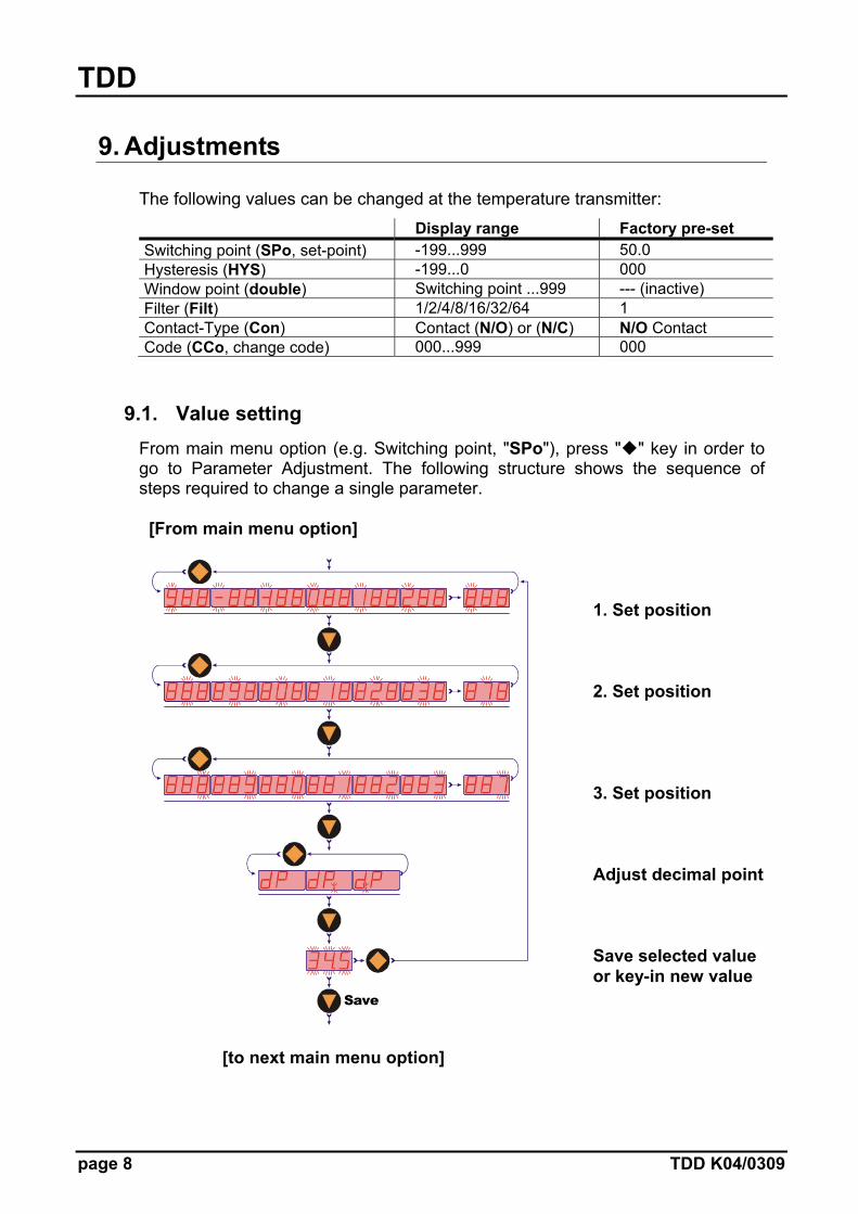
9.1. Value setting From main menu option (e.g. Switching point, "SPo"), press " " key in order to go to Parameter Adjustment. The following structure shows the sequence of steps required to change a single parameter. [From main menu option]
1. Set position 2. Set position 3. Set position Adjust decimal point Save selected value or key-in new value
[to next main menu option]
Save

TDD
TDD K04/0309 page 9
10. Set- up Mode
10.1. Adjustments for TDD-1... and TDD-3...
3 sec
Normal Mode
Anytime:
or 20 secDon’t press any key
: Next level
: Change value
Contact type
N/O contactN/C contact
Save
Off-delay
Setting parameter
Setting parameter
On-delay
Duo-point
Hysteresis
Switch point
Code input
3 secC
ode= Setting parameter
Code change
Setting parameter
Setting parameter
Setting parameter
Setting parameter

TDD
page 10 TDD K04/0309
10.2. Adjustments for TDD-5...; TDD-7...
Setting parameter
On-delay 2
On-delay 1
Setting parameter
Setting parameter
Hysteresis 2
Hysteresis 1
Switch pt. 2
Setting parameter
Switch pt. 1
Code input
3 sec
Cod
e= Setting parameter
TDD
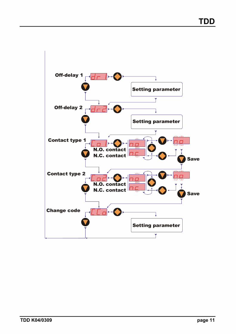
TDD K04/0309 page 11
Change code
Setting parameter
Contact type 2
N.O. contactN.C. contact
Save
Contact type 1
N.O. contactN.C. contact
Save
Off-delay 2
Off-delay 1
Setting parameter
TDD
page 12 TDD K04/0309
11. Main Menu Options
11.1. Switching point In menu option "SP0", “SP1” and “SP2” the switching point is entered. A setting value between -199 and 999 can be selected. This value can also include a decimal point. The decimal point can be set at two points (e.g. 10.0 or 100). If the measuring value is the set switch point, the temperature switch is activated and is signalised by a lightning LED. If the hysteresis is zero and the window point is inactive, the temperature switch will be reacted if the temperature is below the switch point.
11.2. Hysteresis After the setting of switching point, the hysteresis can be entered as a negative value in the "HYS", “HY1” and “HY2” menu. The standard hysteresis value is zero. In operation condition this can lead to ambiguous switching behaviour if the reading fluctuates around the switching point or window point. Aid can be given here by increasing the hysteresis. The hysteresis relates to the switching point and the window point (switching point minus hysteresis; window point plus hysteresis). Example: Switching point 100 °C; Hysteresis: -2.5 °C The temperature switch switches when 100 °C is exceeded and
switches back when the reading drops below 97.5 °C.
11.3. Window point (Double Point), (only for TDD-1… and TDD-3…) As well as the switching point, it is also to define a "duo" (duo-point), the window point. This must be higher than the switching point. Using the window point and the switching point it is possible to monitor the measurement value in a certain range. The switching point limits the measurement range to smaller values and the window point to larger values.
If the window point (duo-point) is less than or equal to the switching point, an error report (Er4) will be indicated on the display and its value is deleted and its function is invalid (in the case that the window point and switching point out of adjustment).
The value is set in the same way as the switching point. The window point is needed for process, monitoring of a certain temperature range.
TDD
TDD K04/0309 page 13
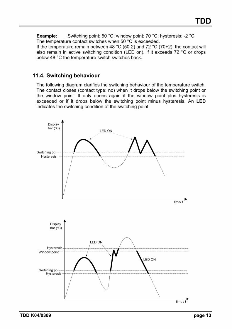
Example: Switching point: 50 °C; window point: 70 °C; hysteresis: -2 °C The temperature contact switches when 50 °C is exceeded. If the temperature remain between 48 °C (50-2) and 72 °C (70+2), the contact will also remain in active switching condition (LED on). If it exceeds 72 °C or drops below 48 °C the temperature switch switches back.
11.4. Switching behaviour The following diagram clarifies the switching behaviour of the temperature switch. The contact closes (contact type: no) when it drops below the switching point or the window point. It only opens again if the window point plus hysteresis is exceeded or if it drops below the switching point minus hysteresis. An LED indicates the switching condition of the switching point.
time/ t
Display bar (°C)
Switching pt. Hysteresis
LED ON
time / t
Display bar (°C)
Switching pt.
Hysteresis
LED ON
Hysteresis
Window point
LED ON
TDD
page 14 TDD K04/0309
11.5. Filter (only for TDD-1… and TDD-3…) The filter function "Filt" makes the measured value for switching purposes the running average from the measured value samples. The following values can be adjusted (see section 9. Adjustments): 1 / 2 / 4 / 8 / 16 / 32 / 64 samples The filter value determines the dynamic behaviour of the display value. The larger the Filt value, the more dampened the display response. With the adjustment of the filter value " 1 " the filter is switched off, i.e. the display value is equal to the unfiltered measured value. The integrated overshoot detector reacts to a step change of approx. 6.25% of the measurement range (full scale). During a detected measured value overshoot of >6.25%, the instantaneous measured value is transferred directly to the display without filtering.
11.6. Transient response (only for TDD-5… and TDD-7…) Using the menu items “dS1”, “dS2”, “dr1” and “dr2” it is possible to set the delay set and the delay reset. The delay set causes delayed switching of the output if the switching threshold is exceeded. The delay reset causes a delayed resetting of the output if it drops below the switching threshold – hysteresis. The setting range for both parameters is 0.0 ... 99.5 seconds. The step rate is 0.5 seconds. With these two functions it is also possible to suppress temporary disturbances.

TDD
TDD K04/0309 page 15
11.7. Contact model In menu option "Con", “Co1” and “Co2” the transistor switching output function is set. The switching function changes from N/O contact to N/C contact, and back. N/O contact means: Contact closes on exceeding the switching point. N/C contact means: Contact opens on exceeding the switching point.
11.8. Change Code The code change "CCo" protects the device against unauthorised changes in adjusted device parameters. If the code is different from 000, the user must input the adjusted code in order to perform any programming changes.
12. Maintenance
This device is maintenance-free when properly installed. However, deposits from dirty liquids can lead to invalid measured values.