opel fuel system notes
TRANSCRIPT

Opel Fuel System Notes
The Opel GT fuel system had been the subject of increasing numbers of inquiries from owners, with many based on returning long-stored vehicles back to drivability, combined with concerns about dealing with operative issues arising from modern fuel blends containing ethanol. Opel GT Fuel System: Overall Layout
There isn’t a single correct answer to many of these questions, as different components have different issues but all fuel system parts have to function well systemically to achieve optimum performance. So here, the most common topics are covered in brief, as a sort of an introduction to each to enable a “checklist” approach of your fuel system, from back to front, with more detailed notes on following pages.
Fuel
Any fuel that is of an unknown age, or known to be 6 months or older, should be drained and safely disposed. Old fuel not only makes it difficult to run an engine, but actually degrades into a harmful “varnish” full of “gum-like” particles that will immediately clog the critical narrow passageways within your carburetor. Modern additives in blends using ethanol causes fuel to more readily separate into layers, one of which can be similar to water (which is particularly harmful to fuel system components made from raw steel).
Tank & Related Hardware
A drained fuel system is ideal for evaluation and service of the original GT fuel tank. Some advocate cleaning the tank with a fluid solvent like B-12 Chemtool, others prefer having the tank removed for a thorough inspection for rust combined with professional service (such as replacing rusted metal sections and/or adding ethanol-resistant coating). Consider replacing the vent hoses, filler neck hose, sender unit and/or gasket, and the tank outlet hose, for safe operation. (Additional details on tank access, removal, inspection and service are on a following page)
Fuel Lines The original fuel system lines can be cleaned with solvent and dried with compressed air. Rubber connector hose ends can be replaced using ordinary fuel line stock, usually sold off a reel on a per-foot price at your local auto part store. The long underbody plastic line often becomes brittle, and can be replaced with new plastic line that is now available. The metal hose which surrounds the front of the engine can be carefully bent, if it is in contact with hot surfaces (such as the lower edge of the upper radiator hose, or hoses connected to the thermostat housing or heater). The metal tank outlet hose requires special attention (see additional details on a following page).
Fuel Filters
Another good idea is to add at least one, and better yet, two clear “see-through” type plastic fuel filters to the system.
Place one near the outlet of the fuel tank, to help catch any rust flakes or other particles from reaching your fuel pump, and so you can verify that adequate fuel is being supplied by the gravity-feed flow from the tank.
(There is also a “hidden” internal fuel screen located near the bottom of the tank, so if you suspect it is getting blocked it can be cleared with a brief use of compressed air through the fuel line—or it can be removed entirely, per instructions available as a separate fuel system “tech tip”)
The other recommended location for an added “see through” fuel filter is in the fuel line just before it reached the carburetor. This serves an important diagnostic function: If the engine dies, a quick look there will help you diagnose if it is caused by insufficient fuel (or something else, such as an ignition system problem).
You can evaluate your fuel system part-by-part, for
best overall function
Plastic “see through” type fuel filter

Fuel Pump Operation
Use a pressure gauge, and verify your fuel pump output is operating within the factory-specified 3.1 to 3.7 psi range of fuel pressure output. Testing is now important, as the ethanol used in gasoline formulas is causing failures of rubber pump diaphragms (particularly when a car sits). When a fuel pump starts leaking fuel or engine oil, it’s time to replace it.
Also be aware that many owners have reported problems with “flat top” design fuel pumps that are being distributed in the US (Opel GT Source only stocks “dome top” type mechanical fuel pumps that are specially imported).
If you have the original style mechanical Opel fuel pump, also check to make sure there is a spacer plate located between the pump and the bottom of the timing cover. Fuel Pumps bolted directly to the engine run hotter and fail much more quickly. Carburetor Mounting Notes
Critical issues that affect Opel driving operation include necessary carburetor mounting hardware and procedures, to prevent a servere vacuum leak commonly found at this location and also to insulate the carburetor from manifold heat (to help avoid ethanol-related fuel boiling).
“Thick style” mounting gasket Installation of this 3/16” thick mounting gasket just below the carburetor helps insulate the body of the carburetor from heat rising directly off the hot intake manifold. Using a sealer like “high tack” also helps seal this gasket from the all-too-common vacuum leak that occurs here too.
Intake Manifold Stud Replacement Original manifold stud threads typically are worn out, and no longer secure the carburetor mount nuts adequately, to prevent engine vibrations from loosening them up. New intake manifold studs are now available (installation notes are on a following page).
Metal “heat shield” Installation of this plate, based on the original Opel aluminum plate which is about 6-8 inches rectangular, helps block rising heat from the exhaust manifold from affecting your fuel system. This shield does require its own separate gasket, which sits on the manifold and is a thin paper type.
Vacuum Leaks Routinely test to check for vacuum leaks at all gasket surfaces, and check operation of all hoses and hardware that connects to the intake manifold. (Additional details on carburetor hardware and service, and dealing with ethanol fuel blends are on the following pages).
Spacer Plate
Gauge
Website: www.opelgtsource.com Phone Orders: 1-800-673-5487 Email: [email protected]
Thick Gasket
Heat Shield
Thin Gasket
Manifold Manifold Studs (4)
Carburetor Identification
When accessing service information or ordering replacement parts, it is necessary to identify the carburetor model you have on your Opel. The original Carburetor was an oval-top Solex downdraft, however most Opels have had these replaced with the aftermarket “Weber” brand downdraft carburetors (which had “squared” tops).
Each brand has its advocates, however for most Opel owners who want easy tuning and dependable vehicle operation, purchase of a new Trademarked (and European-made) Weber is strongly preferred. Opel GT Source offers NEW Webers , along with all necessary parts required for proper installation (depending upon your drivetrain plans). Those who are ready for this improvement are advised to contact us, to discuss how a new Weber can help their Opel.
Solex 5-Bolt, Solex 7-Bolt, and Weber carb tops

Website: www.opelgtsource.com Phone Orders: 1-800-673-5487 Email: [email protected]
Have you experienced difficulty maintaining an idle speed when waiting at a stoplight? Have you experienced difficulties re-starting your car, after it has been parked a few minutes (while you went into a store)? If so, you are not alone! “Heat Soak” and “Percolation” are problems common to vintage vehicles, which are made worse by the increasing amounts of ethanol being blended into available fuels. While technical details are better explained by reading online articles by experts such as Henry Olsen or Jeff Dreibus, presented here are summaries of parts Opel owners are installing to regain driveability. Heat Shielding Installation of a thick carburetor mount gasket (#9004) and a metal heat shield (#9073) help insulate the carburetor from heat radiating off the manifolds.
Cold Air Input Installation of a “dome air kit” (#9063) in combination with components of an original Opel GT air canister system (including a #9024 filter & #9052 hose), will draw in cooler air available from in front of the radiator. (Variations of this approach include a 3” wide pipe and custom K&N filter to relocate the air filter forward as a modern-style cold-air system, or substitution with a #9019 adapter on the carb top).
Electric Fuel Pump Installation of an electric fuel pump (#9066) provides an option of pumping cooler fuel into the carburetor prior to cranking the engine. Use of a block-off plate (#9041) and an additional fuel filter (#9042) for use as a “pre-filter” are also recommended. (We suggest consulting available tech notes when converting to an electric pump).
Starter Upgrade Retrofitting with the newer permanent-magnet style starter (#5027PM) Increases your engine cranking speed and helps a warm engine “catch” better when it is being re-started. Additional upgrades include installation of an electronic ignition kit (#6165) to provide more consistent dwell timing when cranking (compared to the original ignition points), and service or replacement of your ignition switch (#5060N) for better starting.
Service Notes
Each installation of these parts incrementally improves the operation of a classic Opel engine when it is fueled with an ethanol blend. From there, service also helps.
Start by inspecting your fuel lines to make sure they are intact and not in contact with any hot surfaces (like a radiator hose, heater hose, or the engine itself). Consider insulating, or re-routing fuel lines away from heat sources.
Only use fresh fuel (less than 6 months old) and inspect the fuel coming from your gas tank (make sure it is free of varnish or rust). If necessary, consider having your gas tank professionally re-coated for rust protection.
Installation of exhaust headers or a “sprint” manifold can also reduce heat at the carb.
Carburetor re-jetting is best done where professional testing equipment (such as a wideband O2 sensor, or HC/CO output readers) is available, and performance results will vary where fuel blends are altered seasonally.
Some old-schoolers also advocate spraying with a small water bottle or wrapping a wet rag around a hot fuel line, as a “side of the road” remedy.
Shield and Gasket help deflect heat coming off the exhaust manifold
9004
9073
Ethanol and your Classic Opel
9066
9041 9042
5027PM
A Cold Air System can be constructed with an original GT Air Canister, or modified with a
tube and a modern “cone” type K&N filter
Electric Fuel Pump and Installation Components
A “Permanent Magnet” starter provides better engine cranking
9063
9052
(air filter)

Intake Manifold Stud Kit #9034W: Install Notes
The most common causes of driving issues on Classic Opels are vacuum leaks, which often result in difficulty maintaining an idle, a ‘stumble and surge’ response to acceleration, and poor performance combined with even poorer gas mileage.
The most significant recurring problem is a major leak where the carburetor is mounted onto the top of the manifold. Age and wear on the intake manifold stud threads results in situations where owners feel a need to over-tighten existing hardware, which can result in additional problems such as the base plate of the carburetor becoming warped.
Step One: Carburetor Removal
Stud replacement is far easier performed with the carburetor removed from the intake manifold. To do so, disconnect hoses to the air filter, disconnect vacuum hose from side of the carburetor, remove existing mount nuts and washers, disconnect and plug the fuel hose, and as you are lifting the carburetor free from the manifold, unclip and disconnect the throttle linkage from the carb's "ball fitting". Tools required include a pair of open-end wrenches to fit the most common nut sizes (typically 13mm or 12mm), along with screwdrivers and a vice-grip or a crescent wrench.
Use this procedure for removing old existing studs:
(1) Install a nut about halfway down the top of a stud. (2) Install a 2nd nut, then finger-tighten it until it is on top of the first nut (3) Tighten nuts against each other, by wrenching the lower nut upwards while at the same time tightening the upper nut downwards. (4) Once nuts are tightened solidly, the stud can be removed by simply wrenching the lower nut counter-clockwise. (5) Repeat this process until all 4 studs are removed. (6) Use solvent spray and blade as needed, to clean rectangular upper manifold surface of any remaining grease/sealer/gasket pieces.
To install new replacement studs:
(1) Apply a drop of blue "loc-tite" liquid to thread of stud (2) Thread new replacement stud finger-tight into manifold. (3) "Double Nut" the stud, using techniques described above. (4) Rotate upper nut clock-wise, until stud is torqued securely into place. (5) Separate nuts by wrenching lower nut clock-wise, while rotating upper nut counter-clockwise. (6) Unscrew each nut separately, one at a time, from stud. (7) Repeat this process, until all 4 studs are in place on manifold
(Stud threads are 8mm x 1.0 pitch on top & 8mm x 1.25 pitch on bottom)
“Double Nut” Technique
(Left) Tightening nuts together on stud
(Right) Stud shoulder “snug” in position
Opel GT Source has long-supported a pro-active approach to resolving vacuum leaks, including offering a full line of
replacement seals and a special thicker carb mount gasket. To help restore Opel performance, Opel GT Source has also
manufactured a new line of replacement intake studs, custom-designed for installation for Weber carbs on classic Opels.
To help owners successfully install this new hardware, illustrated notes which follow have also been compiled.
We suggest starting by acquiring a stud kit, new gasket(s), sealer(s), and appropriate tools and supplies as will be required. Intake Manifold Stud Locations
(Left) Intake Manifold, Old Studs removed
(Right) Intake Manifold, New Studs in Place
Use a short wrench to turn the rear
passenger-side nut
Install
Remove

Solex Carburetor: The Basics
The key to running an Opel with an original Solex carburetor, appears to be finding one that has relatively low mileage and which has not been run much in driving situations that exposed it to heat.
Because Solexes were found to be so vulnerable to damage from heat warpage (developing an annoying tendency to idle at varying speeds) and internal part failure (causing them to continually dump gas), OMC has advised Opel owners who wish for reliable driving performance to instead retrofit with a Weber carburetor.
For those who enjoy a challenge (or who wish to be 100% factory-original), some basic installation and tuning information is presented here. A thorough carb cleaning, and re-machining of the Solex base plate (to flatten it), may also help. As noted on a prior page, Solex models did vary with car models and year applications (tag numbers applications were listed in the OMC Blitz of 7/2008).
Basic Carburetor Adjustment (A) Ensure the linkage is free. Lubricate or free if necessary
(B) Close idle air adjust screw (#3)
(C) Adjust Throttle Stop Screw (#1) and Idle Mixture Screw (#2) alternately to obtain smoothest idle at 650-700rpm.
(D) After best possible mixture has been obtained, do not move (#1) again.
(E) Using (#3), raise idle speed to 800-850rpm (automatic trans) or 850-900rpm (manual transmission)
(F) Using (#2) and (#3) alternately to obtain smoothest idle at 800-850rpm (automatic) or 850-900rpm (manual transmission).
(G) After adjustment has been completed, ensure that engine will return to idle after raising engine speed.
More detailed Solex repair procedures can be found in the 1973 Opel factory service manual, some
Opel technical bulletins (and the OMC Blitzes of 12/1995 and 4/1994).
Some factory-specified settings
do require the use of obscure tools (like a water manometer).
OMC’s drivers largely gave up on
trying to find workable solutions to keep the original Solex carburetors operating
(back in the 1980’s) in favor of Weber carbs.
OMC does not guarantee your results!
Carbon Canister Hoses
Hoses to the carbon canister (mounted next the battery) connect to ports (on the engine-facing side) of the Solex carburetor.
Distributor vacuum hoses
Carbon canister hoses
Air Filter System Hoses
(AF-1) A formed hose is inserted into the large port on the valve cover.
(AF-2) An oval rubber boot, connects to the round air filter canister
Float
The Solex’s internal float is prone to fuel saturation, which may result in flooding. When this occurs, its tab can be bent slightly (to raise its level in the float bowl). (AF-1) (AF-2)
(#2)
(#1)
(#3) (from 1970 Opel factory procedure)
Carbon Canister
Opelclub.com 9/2009
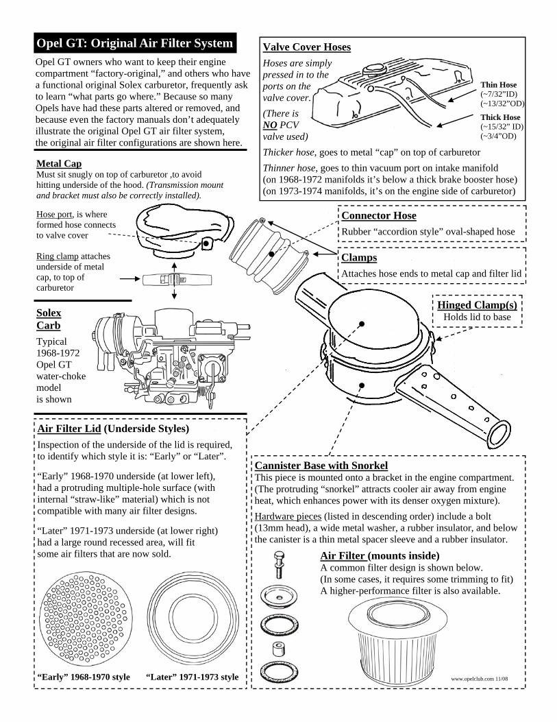
Opel GT: Original Air Filter System Valve Cover Hoses
Hoses are simply pressed in to the ports on the valve cover.
(There is NO PCV valve used)
Thicker hose, goes to metal “cap” on top of carburetor
Thinner hose, goes to thin vacuum port on intake manifold (on 1968-1972 manifolds it’s below a thick brake booster hose) (on 1973-1974 manifolds, it’s on the engine side of carburetor)
Opel GT owners who want to keep their engine compartment “factory-original,” and others who have a functional original Solex carburetor, frequently ask to learn “what parts go where.” Because so many Opels have had these parts altered or removed, and because even the factory manuals don’t adequately illustrate the original Opel GT air filter system, the original air filter configurations are shown here.
Metal Cap Must sit snugly on top of carburetor ,to avoid hitting underside of the hood. (Transmission mount and bracket must also be correctly installed). Hose port, is where formed hose connects to valve cover Ring clamp attaches underside of metal cap, to top of carburetor
Thin Hose (~7/32”ID) (~13/32”OD)
Thick Hose (~15/32” ID) (~3/4”OD)
Solex Carb
Typical 1968-1972 Opel GT water-choke model is shown
Cannister Base with Snorkel This piece is mounted onto a bracket in the engine compartment. (The protruding “snorkel” attracts cooler air away from engine heat, which enhances power with its denser oxygen mixture).
Hardware pieces (listed in descending order) include a bolt (13mm head), a wide metal washer, a rubber insulator, and below the canister is a thin metal spacer sleeve and a rubber insulator.
Air Filter (mounts inside) A common filter design is shown below. (In some cases, it requires some trimming to fit) A higher-performance filter is also available.
Connector Hose
Rubber “accordion style” oval-shaped hose
Hinged Clamp(s) Holds lid to base
Clamps
Attaches hose ends to metal cap and filter lid
Air Filter Lid (Underside Styles)
Inspection of the underside of the lid is required, to identify which style it is: “Early” or “Later”. “Early” 1968-1970 underside (at lower left), had a protruding multiple-hole surface (with internal “straw-like” material) which is not compatible with many air filter designs. “Later” 1971-1973 underside (at lower right) had a large round recessed area, will fit some air filters that are now sold.
“Early” 1968-1970 style “Later” 1971-1973 style www.opelclub.com 11/08

Solex Carburetor Rebuild Kits, 1.9 Engines:
9021 Solex Rebuild Kit, 1968-1974 (1.9 engines) (Specify if your upper carburetor cover has a 5-bolt or 7-bolt original design )
You can identify if you have the original Solex carburetor (downdraft, 2-barrel) by its resemblance to the illustrations at right. There were 2 basic Solex styles originally installed on 1968-1974 Opels, including an earlier “5-bolt” upper cover and a later “7-bolt” upper cover. There were also choke applications that varied by Opel models and years, including water, electric, and manual choke. You can consult Opel reference guides (if you need to verify a Solex is an exact year/model original version). Original Solex 2-barrel carburetors can run well and offer good fuel efficiency, when they have relatively low miles on them and are undamaged. Unfortunately, because they are mounted on top of the hot exhaust manifold, air passages inside the all-aluminum Solex body typically become warped by heat, and cause the carburetor’s operation become unreliable (with symptoms of difficult starting and an inability to maintain a consistent idle speed). Internal part failures are also common. If and when this occurs, we advise an Opel owner to consider replacement with an aftermarket Weber carburetor.
Typical Solex
Installation
1968-1970 style 1971-1973 style
Inspect underside of canister lid
Original Opel GT Air Filter Housing Styles
A required inspection is the underside of the top lid of the GT Air Filter Housing.
1968-1970 GT’s originally had an “oil bath” air cleaner (a lid with many holes, filled with a straw-like material) which protrudes too far to allow
some air filters to be installed as-is.
Later 1971-1973 lids had a large round recessed area, that is the style that is more compatible with some air filter elements.
5-bolt Solex 7-bolt Solex (added bolts indicated)
Solex-compatible Air Filter Hoses 1.9 engines: 9052 Connector Boot for Solex Air Cleaner
9053 Formed Hose, Valve Cover to Solex Air Cleaner Solex-compatible Air Filters 1.9 engines: 9024 Original GT Air Filter Element, Opel GT (for original round air filter element style) 9024K&N High-Flow Air Filter (performance and longevity upgrade, for original air filter element style)
9021 (Rebuild
Kit)
9024 9024K&N
9052 9053
Opel GT “Solex” Carburetor Parts
www.opelgtsource.com Orders: 800-673-5487 Info/Intl: (209) 928-1110 Email: [email protected]

Opel GT Fuel System: Fuel Tank and Hardware
Snug within protections of the rear sub-frame, sits the Opel GT’s fuel tank. It’s compact design holds a factory-rated 14.5 gallon capacity. An important safety procedure is to first replace all common-wear items (such as the vapor vent hoses, rubber filler neck, and sender unit gasket), to keep potentially explosive fumes from accumulating within the cars’ interior. Opel fuel tanks are an all-steel design and are now subject to internal corrosion. Rust occurs within tanks that have been stored for years, when water separates out of old gas and sinks to the bottom. Tanks that were left unprotected also attract condensation, which develops a layer of rust wherever it collects. Sediment also clogs an internal tank “fuel sock” which can affect your performance. Treatment for rust varies, and generally requires removal of the tank from the car (separate interior removal procedures are shown on the next page). Also verify that your fuel gauge rises and falls with the tank level, if it doesn’t then test the sending unit and circuit.
Once the tank is removed from the car, some light internal rust can be scraped off by dropping loose nuts and bolts within the tank, then shaking it back and forth.
Some tanks need a more thorough cleaning combined with internal recoating: Use an ethanol-resistant blend (NOT fiberglass). Some have used 3-part etching/coating/liner products, like “KBS”. Other tanks require a replacement metal panel (with a matching threaded hole) to be welded at the bottom.
The only other alternative, is searching for a complete good used replacement tank (that is not rusted itself, and which is reasonably priced).
Fuel Gauge Sending Unit & Gasket When your gauge doesn’t provide readings,
try this simple test: If grounding the blue/black wire on the tank causes the
needle on the fuel tank gauge to read “full,” then this sender may not be working.
If the float is sticking, you can remove this unit then try spraying carburetor cleaner spray through the small holes in the side of the unit. Then connect
the blue/black wire and ground its case, then “tilt” it and try to read the gauge.
Disassembly and repair of the sender is best left to an experienced professional.
This unit has special resistance wires (which break easily), and a rod end &
internal brass connectors which are prone to corrosion. Its fragile metal canister is
also easily dented or damaged.
Hose, Filler Neck & Gas Cap Gaskets
The rubber hose, the filler neck to body
gasket and the (internal) gas cap
gasket provide important safety
functions that help keep gas fumes
restricted to (and filtered by) the tank ventilation system.
As the original pieces are now all over 40
years old, they should all be replaced when maintenance on the
fuel tank is performed.
Gasket: Scrape off old gasket carefully (away from tank hole). Use sealer on replacement.
Opelclub.com 9/2009
Information compiled in this guide is provided in part via permission from the Opel Motorsport Club All rights to original text and images are reserved.

Fuel System: Fuel Tank Removal
Almost all fuel tank maintenance procedures require removal of the interior spare tire support hardware to be able to access the replaceable parts. This requires removing the tire hold-down cage, a structural support piece, and the 10mm bolts that secure the wide flat board in place. It is suggested that you note where each bolt was removed from (by placing tags with them in baggies). You will need to move the car seats forward and open a door all the way, to be able to carefully remove the large wood shelf.
Fuel Outlet Tube and Fitting
Removal of this metal tube and fitting is only required when it is leaking gas or when the tank must be removed from the car. Because rust often develops here, you should lubricate this fitting (with WD-40 or PB-Blaster) repeatedly (over a few days) before you start work.
Removing the fitting is challenging. Easiest access is with a 17mm “offset” type “box end” wrench (slipped over the end of the fuel tube). If you can’t get one, you can try to “tap” the edges of the body access hole (until an open-end wrench will be able to reach the nut edges). Make sure any work you do is even, so the rubber boot that fits around this tube will secure its lips evenly (after you are finished). Or, if you already have a tube in hand, you can hacksaw the old metal
tube (close to the tank) and use a deep 17mm socket to remove the 17mm nut & then the 17mm fitting.
Because this tube is equipped with an internal “crush” sleeve, it may develop a leak if it is re-installed. To be safe, we suggest installing new replacement tube & fitting.
Tank Fitting/Nut
Metal Tube
Spare Tire Hinge Mount Removal Removing Fuel Tank Rail Mounts
Removing the spare tire support board requires
removing the two 10mm nuts from
within the passenger side rear wheel-well.
Removing the fuel tank itself,
requires removing the two 10mm nuts
from within the rear wheel-wells
of both sides of the car.
Often, these appear as “bumps” (at the locations shown in the diagram at left), as they typically have a thin layer of old dried rubber
undercoating over them (which can be scraped off with a screwdriver).
About 14” above center of wheel
1 5/8” apart 10mm nuts
Fender Lip
Tire Edge Location varies, with size of tire
About 7” apart
(10mm nuts)
Fender Lip
Bolt locations, as indicated
Offset-type 17mm
box- end wrench
@1 1/4” offset
Opelclub.com 9/2009

Fuel Pumps
Original Opel fuel pumps were mounted on the lower side of the engine’s timing cover. Minimum required fuel pressure for carbureted engines is 2.5psi. Installation of an inline fuel pressure regulator (adjustable to 3.5psi) may also increase your fuel efficiency.
9010 Fuel Pump, 1968-1974 All Opels with 1.9 Liter 6051 Fuel Pump Spacer Plate (Required for installation of #9010 fuel pump) 9041 Steel fuel pump block-off plate. (For converting 1968-74 engines to electric fuel pump). 9066 Electric Fuel Pump, Posi Flow
9010
6051
9037 or 9037A
Important: Inspect and replace gas tank vent hoses (especially if you detect a fuel odor, when tank is half or more full)!
Opel GT Fuel System Parts
NOTE: Many Good Used Opel Fuel System Parts are also available, Contact Opel GT Source & ask!
Gauge markings are based on the 14 gallon capacity of the tank. (Half = 7 gallons Red = 1.75 gallons)
Readings are based on the condition of your fuel tank sender and circuit (so accuracy may vary)
9013
9014
9061
9043 9044 13020
9007 9049
9037
9037
9044 13020
9043
Gas Tank-Related Parts A critical safety requirement is inspection and maintenance of GT gas tank-related hardware,
including vent lines, gaskets & hoses.
When accessing the gas tank, it’s easiest to replace all service items at once
(using the diagram here to identify parts).
9007 Fuel Line to Body Boot, Opel GT 9014 Filler Neck Gasket, Reproduction, Opel GT (This fits on the body opening below the gas cap)
9037 Gas tube vapor lines, 12', with instructions, 9037A Gas tube vapor lines, 12’, with “tee fittings” 9049 Metal gas tank fuel line and fitting, includes new metal crush sleeve, Opel GT 9061 Gas Filler Neck Hose, Opel GT. 9068 GT Plastic Fuel Line, underbody to fuel pump 9ft
9044 GT Fuel Tank Sending Unit 13020 Gas Tank Sender Rebuilding Service (See “part rebuilding” page for details) 9043 Fuel tank sending unit gasket, Opel GT.
9013 Gas Cap with Keys, Opel GT 9047 Gas Cap Rubber Gasket, Opel GT 12037 Key Blanks for Gas Cap (OP 19)
9071 Upper Gas Tank “All-In-One, Reseal Kit” Includes #9037A, #9061 and #9043
9071 “Kit” Includes
9037A, 9061 and 9043
(1973 has extra port)
(Rear of tank)
(Top of tank)
9068 (to fuel pump)
www.opelgtsource.com Orders: 800-673-5487 Info/Intl: (209) 928-1110 Email: [email protected]