ontology-based design of space systems defence and space, space systems, friedrichshafen, germany...
TRANSCRIPT

adfa, p. 1, 2011. © Springer-Verlag Berlin Heidelberg 2011
Ontology-Based Design of Space Systems
Christian Hennig1, Alexander Viehl2, Benedikt Kämpgen2, and Harald Eisenmann1
1Airbus Defence and Space, Space Systems, Friedrichshafen, Germany {christian.hennig,harald.eisenmann}@airbus.com
2FZI Research Center for Information Technology, Karlsruhe, Germany {viehl,kaempgen}@fzi.de
Abstract. In model-based systems engineering a model specifying the system's design is shared across a variety of disciplines and used to ensure the consisten-cy and quality of the overall design. Existing implementations for describing these system models exhibit a number of shortcomings regarding their approach to data management. In this emerging applications paper, we present the appli-cation of an ontology for space system design that provides increased semantic soundness of the underlying standardized data specification, enables reasoners to identify problems in the system, and allows the application of operational knowledge collected over past projects to the system to be designed. Based on a qualitative evaluation driven by data derived from an actual satellite design pro-ject, a reflection on the applicability of ontologies in the overall model-based systems engineering approach is pursued.
Keywords: Space Systems, Systems Engineering, MBSE, ECSS-E-TM-10-23, Conceptual Data Model, OWL, Reasoning.
1 Introduction
The industrial setting for producing systems to be deployed in space, such as satel-lites, launch vehicles, or science spacecraft, involves a multitude of engineering disci-plines. Each involved discipline has its own view on the system to be built, along with its own models, based on its own model semantics. For forming a consistent picture of the system, information from all relevant discipline-specific models is integrated towards an interdisciplinary system model, forming the practice of model-based sys-tems engineering (MBSE). Usually the data used to describe these system models is specified in technologies focused on software specification, such as UML or Ecore. However, these means of specification fail or neglect to address a number of important aspects. Semantic accu-racy is often sacrificed for efficient implementation, the interdisciplinary nature of the engineering process is neglected in its data specification, and mechanisms for deriv-ing knowledge from the information stored in the system models do not exist. This emerging applications paper demonstrates how using OWL 2 ontologies for model specification addresses existing shortcomings in describing system models, making the following contributions:

• Outlining of shortcomings of the established industrial data management practice used in space system engineering .
• Delivery and application of an ontology for model-based space systems engineer-ing for supporting numerous activities involved in a satellite's design.
• Demonstration of the utility of an OWL 2 conceptual data model for solving cur-rent problems in the context of MBSE.
• Critical discussion on how OWL 2 can fit into current industrial data management and model-based systems engineering settings.
The ontologies developed for this paper are available online under Creative Commons licensing. Details on how to access the ontologies can be found in section 4.2.
2 Model-Based Systems Engineering at Airbus DS
2.1 The Practice of Systems Engineering
In many industrial domains today, and especially in the space community, a multitude of disciplines is involved in creating a product. For space projects such as satellites, launch vehicles, or resupply spacecraft these disciplines involve, only to name a few, mechanical engineering, electrical engineering, thermal engineering, requirements engineering, software engineering, verification engineering, and their respective sub-disciplines. Each of these disciplines specifies, designs, and verifies specific parts or aspects of the system. In order to provide an all-encompassing understanding of the system of interest, the unique, yet complementary, views from every involved disci-pline are combined. The science and art of integrating different views on one system towards system thinking is called Systems Engineering. As NASA [1] elegantly puts it: “Systems engineering is a holistic, integrative disci-pline, wherein the contributions of structural engineers, electrical engineers, mecha-nism designers, power engineers, human factors engineers, and many more disciplines are evaluated and balanced, one against an-other, to produce a coherent whole that is not dominated by the perspective of a single discipline.”
2.2 Model-based Systems Engineering (MBSE)
Many of the engineering activities performed within these disciplines are already well supported by computer-based models. Mechanical design models built with tools such as CATIA V5, mechanical analysis models built with tools such as PATRAN and thermal analysis models built with tools such as ESATAN-TMS are well established in the space engineering community today. Furthermore, requirements models based on DOORS play an important role, while also “traditional” tools such as Excel or Visio are used on a regular basis for specifying models.
Some tools provide an automated data exchange interface to other tools inside their own domain, e.g. in the case of mechanical design and mechanical analysis. However, classically, most engineering tools have been regarded in isolation from each other. Personal communication and documents are usually the main mechanism for bringing information from one domain into another one. Such a manual information manage-ment process is a pragmatic approach that can easily be established as it does not

involve a lot of technical prerequisites, but is generally regarded as error-prone, pro-ducing inconsistencies, and involving a high amount of coordination overhead.
In order to cope with the shortcomings imposed by manual data integration, a fur-ther integration of these engineering tools is being pushed by the systems engineering community in numerous industrial sectors, including the space business unit of Airbus DS [2, 3]. The approach of MBSE focuses on employing a truly interdisciplinary representation of a system that incorporates design information of relevance to all domains. A common approach to achieve this kind of system-level data integration is employing a system model that serves as a central hub integrating the different model-ing paradigms, and model semantics. This architecture is visualized in Fig. 1.
Fig. 1. System model as hub for integrating information from different engineering tools
For the purpose of designing space systems at Airbus DS, a product line of system engineering tools [4] has been developed that manages the system model. This model contains artefacts of system-wide relevance such as requirements, the product struc-ture, operational modes, geometric properties, or verification approaches and traces between those artefacts. For the purpose of easing integration across engineering dis-ciplines, and easing integration across the whole customer-supplier chain along multi-ple companies, the specification of these artefacts is done in a conceptual data model (CDM) that is shared between many stakeholders from the European space communi-ty, including the European Space Agency (ESA) and Airbus DS. This common data model, forming the meta-model to the system model, has been defined in a specifica-tion called ECSS-E-TM-10-23A [2] (abbreviated 10-23) and is specified using UML. It has been implemented in a number of tools, such as those employed in the Virtual Spacecraft Design Project [5], the SVTLC and FSS ESA TRP activities [6], in the EGS-CC project [7], and in Airbus DS’ internal system engineering product line [4].
2.3 Shortcomings of Data Management Approach in Use By Current Tools
The current approach to describe system models neglects to address a number of im-portant aspects that are of essential relevance to the MBSE domain. These points originate from shortcomings (SCs) identified in the Airbus DS data management ap-
Verification Engineering
DOORS Requirement
DB
Mission Design System Model
Mechanical Engineering
CATIA Design Model
Systems Engineering
PATRAN Analysis Model
Simulator Engineering
Access Verification
DB
Excel Power Budget
SysML Functional
Specification
SimTG Equipment
Models MATLAB
Orbit Model
EMF TM/TC
DB
Excel Mass
Budget

proach, but are generalizable for other modeling approaches based on similar specifi-cation technologies.
SC1 - Semantics sacrificed for ease of implementation: The necessity for cost-efficient deployment of a system modeling application often leads to using generic structures for defining central concepts, as is the case for the Product Structure of 10-23. These generic structures ease implementation and applicability to a wide range of systems, but their logical consistency is not necessarily ensured. For instance, a sys-tem element might be a piece of software, but also exhibit mechanical properties, such as mass, being intuitively incorrect, but nevertheless possible in the system model.
SC2 - Inadequate tailoring support: In the space engineering community, the prac-tice of tailoring is very dominant, meaning that selected engineering standards are adapted (albeit in a limited way) for each individual project. This implies that specific data structures have to be changed for every individual project, leading to high adap-tion cost.
SC3 - Missing discipline context information on elements: Although the need for having a system model comes from an interdisciplinary problem, this interdisciplinary nature is not directly reflected in the CDM. Consequently there is no logical link that allows a derivation of which engineering discipline is involved with which system element, falling short of improving discipline management and coordination.
SC4 - No exploitation of existing system design data: As the main purpose of cur-rent databases is data storage, versioning, and exchange, using system description data for other purposes, such as logical soundness checking, is currently not done.
SC5 - No existing knowledge capture and application mechanism: There is no mechanism for continuously gathering and formalizing knowledge across numerous projects, and making it available for application to future projects, steadily improving system quality as more knowledge becomes available.
2.4 Related Work on Describing System Models
Describing a system model in the MBSE context can also be done using other, yet similar, means. On the one hand, the System Modeling Language SysML [8] has been gaining a lot of traction and can be employed for the functional specification of a system using tools such as Papyrus [9]. On the other hand, a tool named Capella [10] surfaced, implementing the Arcadia meta-model, and supporting the Arcadia method [11]. In the case of SysML, being a profile to UML, the CDM’s specification lan-guage is MOF [12] while the Arcadia data model is described using the modeling language of EMF, Ecore [13]. Further approaches include the Open Concurrent De-sign Tool (OCDT) [14] and the Concurrent Design Platform (CDP) [15].
3 Improving the System Modeling Approach Using OWL 2
3.1 Improvement of System Model through Employment of OWL 2
For overcoming the shortcomings associated with system models based on object-oriented specification languages, describing the system model and the CDM with an ontology description language is proposed. The motivation behind this approach is

based upon the following assumptions: Improvement of system model semantic accu-racy (SC1), support of tailoring (SC2), classification of elements according to their engineering discipline (SC3), and further improvement of system model utility by inferring new information with help of a knowledge base (SC4 and SC5).
"Re-hosting" of the conceptual data model started with a manual transformation of the original 10-23 UML meta-model according to pre-defined transformation rules, transforming entities and relations. Subsequently operational knowledge from engi-neering domains contained in system design documents was formalized and discussed with discipline experts. A validation followed in order to ensure that data from both documents and the 10-23 meta-model is able to accurately be represented by the MBSE ontology. This approach, along with further information on the evaluation approach, is illustrated in Fig. 3.
The decision to use OWL 2 was reached by determining the semantic expressivity required by the MBSE ontology. One evaluation case relies heavily on using disjoints between classes, eliminating RDF(S). The MBSE ontology also exploits concepts such as reflexive properties and sub-property chains that are covered well by OWL 2. This leads to the question if an OWL 2 profile can be used in order to benefit from a performance advantage. The MBSE ontology uses inverses of object properties, rul-ing out OWL 2 EL. OWL 2 QL is ruled out since, as already mentioned, property chains are required. Some classes state information about yet unknown individuals in their superclass expressions, ruling out OWL 2 RL. Consequently, required expressiv-ity can only be supplied using OWL 2.
3.2 Related Work on Ontological Modeling of Engineering Data
Numerous authors have been considering the role of ontologies in the systems engi-neering context [16, 17, 18]. While these considerations contain valuable remarks and highlight issues, the works do not provide usable solutions.
An approach regularly pursued is modeling engineering vocabularies using OWL or other ontology languages, instead of their native description language. This was done, for example, with ISO 15926 [19], and ISO 15288 [20]. The main purpose of these activities is to provide better communication and more accurate specification of data. The idea of integrating SysML with OWL has been proposed [21, 22] in order to improve modeling semantics. However, due to the remaining implicit semantics of the engineering domains to be distinguished, this approach does not fulfill the need for semantically driven consistency within the engineering domains and between them.
Another approach is specifically constructing engineering ontologies, as Borst [23] does for the purpose of better facilitating knowledge sharing and reuse. Van Renssen [24] even coins his own ontology and vocabulary, Gellish, for describing engineering facts. The goal of both approaches also does not go further than modeling, sharing, and reusing, however.
Some authors do apply reasoners to their engineering ontologies. Jenkins [25] uses inference along the taxonomic structure of system elements in order to query the sys-tem model more easily. Graves [26] suggests using inference in order to evaluate design consistency in terms of violated constraints. Takker, et al. [27] employ OWL and inferencing for coming to diagnoses of tunnel disorders by examining the mod-eled set of symptoms observed in tunnels. Abele, et al. [28] use the same technologies

for validating design consistency of industrial plant models. Feldmann, et al. [29] use SPARQL queries for specifying and finding design problems. Wende, et al. [30] also check basic consistency of domain models using reasoning.
This paper picks up at consistency checking, but goes beyond the use cases de-scribed by the works above. On the one hand, we approach the multi-disciplinary problem of MBSE by determining the responsibility of engineering disciplines in specific system building blocks using inference. Furthermore, we perform engineering tasks automatically that were entirely manual processes before. Also, we enable new engineering activities by making information explicit that was only implicitly scat-tered across system models before, and introduce a knowledge base to engineering activities.
4 Evaluation of Ontological System Modeling Approach
4.1 Definition of Evaluation Scenario
For evaluating the improvements enabled by re-hosting the system model using on-tology modeling technologies, the approach outlined in 3.1 will be demonstrated us-ing examples based on data derived from an actual satellite design, resulting in the satellite dataset. This mission is representative for a mission in Phase B of the ESA project cycle [31], close to the Preliminary Design Review (PDR), utilizing data de-rived from a real project wherever possible. Data subject to intellectual property own-ership issues was deliberately left out. For providing the necessary data to demon-strate this research, the ontologies are extended in a representative manner at required points with data not covered by the established engineering processes. This approach allows using project data not subject to intellectual property issues whenever possible, and to extend this data at specific points when required for demonstration purposes.
Fig. 2. Isometric view and side-views of the satellite
Structure Electric Power Subsystem Data Handling Subsystem Telemetry, Tracking, and Telecommand Subsystem Attitude and Orbit Control Subsystem Instruments

The goal of the spacecraft's mission is to measure the Earth’s magnetic field using a set of specialized instruments, along with other scientific experiments. More specif-ically, the mission consists of a constellation of numerous identical satellites which are approximately 5 meters long, 1.4 meters in width, 0.8 meters in height, and weigh-ing 600 kg. The mechanical design of these spacecraft is illustrated in Fig. 2.
This object-oriented satellite system model, based upon a derivation of 10-23 data specified in UML, is re-hosted in an ontology specified in OWL 2, consisting of a concept ontology (MBSE Ontology) and an ontology containing instance data of the satellite (satellite dataset). The transformation for object-oriented satellite instances to OWL individuals can principally be done in an automated, generic fashion, since it is a very direct instance mapping, but is done manually in the scope of this paper for pragmatic reasons.
Fig. 3. Illustration of evaluation approach
A number of evaluation cases are provided that rely on usage of both satellite da-taset and MBSE ontology. These cases pick up on the shortcomings identified in 2.3, giving a proposal on how to solve them with OWL 2, resulting in the provision of objective evidence that the shortcomings have indeed been solved using an OWL 2 ontology. This evaluation approach is illustrated in Fig. 3.
4.2 Availability of Employed Ontologies
Both MBSE ontology and satellite dataset are available at Zenodo under Creative Commons Attribution-ShareAlike (CC BY-SA) license and may be accessed via the following DOIs:
http://dx.doi.org/10.5281/zenodo.57955 (MBSE Ontology) http://dx.doi.org/10.5281/zenodo.57957 (Satellite Dataset)
These ontologies have been spawned through research on using ontologies in the model-based systems engineering context. Being research on the future functionality of system models, these ontologies have not yet been rolled out to actual end-users in an industrial deployment process. The team involved in ontology design and design of
Evaluation Case Evaluation Case
Object-Oriented Satellite
System Model
Object-Oriented 10-
23 CDM
UML OWL 2
MBSE Ontology
Ontological Satellite System Model
(Satellite Dataset) Engineering Documents
Manual transformati-on giving ontological
flavor
Manual instance migration
Ontological formalizati-on of knowledge
Evaluation Case Evaluation Case
Evaluation Case
instance of
manual transfor-mation
demonstration

the infrastructure around them consists of three researchers, with a significant contri-bution from domain experts. Both ontologies will continue to be maintained and ex-tended.
The evaluation scenario is based upon the MBSE ontology in version 1.1, and the satellite dataset in version 1.1. Modeling was performed using Protégé 5.0.0. Reason-ing was done using PelleT 2.2.0. Inferring all statements on the MagSat dataset takes an average of 24 seconds on a Core i7 4th generation quad core CPU at 2.8 GHz with 16 GB of RAM.
4.3 Evaluation Cases
The five selected evaluation cases together encompass activities from the beginning of a project in Phase 0/A up to system production in Phase D. Their allocation to dif-ferent system design phases is illustrated in Fig. 4.
Fig. 4. Positioning of evaluation cases along the system design cycle
Evaluation and Insurance of Property Consistency. A significant part of describing space systems is done with physical properties. Based on these properties, assertions can be made, such as that a Star Sensor has a mass with the value 0.380, based on the physical quantity mass, and the unit Kilogram. The assertion of such properties is based upon the SysML QUDV standard [8] and is employed as reusable library that can be loaded into multiple projects and adapted accordingly. In order to be applica-ble to virtually any data model element, the implementation of these properties is a generic structure as outlined in SC1. However, there exist certain data model elements that are not applicable to any properties, and combinations of properties that do not make sense to occur together. More specifically, through employing such a generic structure, the possibility to specify inconsistent model populations emerges.
For example, a property of powerConsumption in Watts could be attributed to a screw, a software could exhibit dimensions in length, width, and height, or a battery could have a data rate. While these assertions are illogical at first glance, modeling mistakes do happen. In other cases, errors are more subtle. For example a component should get the mass property for items on component level, while subsystems have a mass property that is composed of mass, margin, and nominalMass, whereas the satel-lite on system level exhibits nominalMass, margin, totalDryMass, and totalWetMass (including propellant and other fluids required for full operation).
Phase 0/A Phase B Phase C Phase D
Allocation and Management of Disciplines
Evaluation and Insurance of Property Consistency
Generation and Administration of CIL
Identification of Required Tests
Identification of Test Sessions
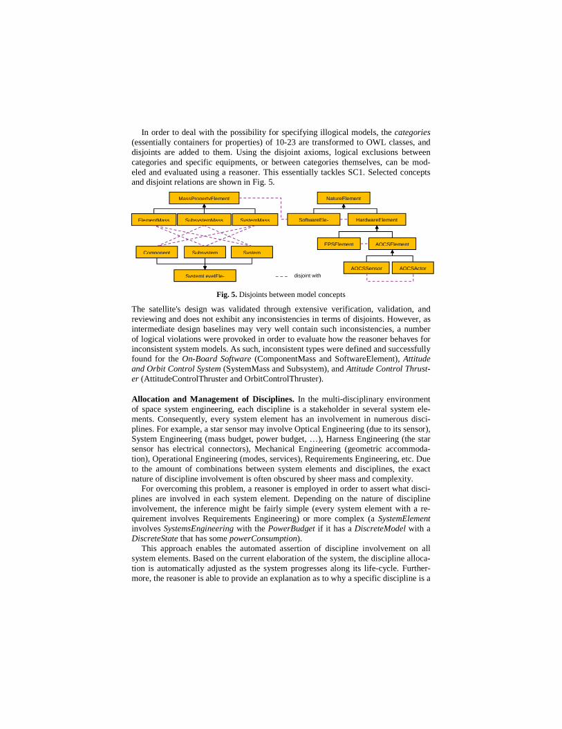
In order to deal with the possibility for specifying illogical models, the categories (essentially containers for properties) of 10-23 are transformed to OWL classes, and disjoints are added to them. Using the disjoint axioms, logical exclusions between categories and specific equipments, or between categories themselves, can be mod-eled and evaluated using a reasoner. This essentially tackles SC1. Selected concepts and disjoint relations are shown in Fig. 5.
Fig. 5. Disjoints between model concepts
The satellite's design was validated through extensive verification, validation, and reviewing and does not exhibit any inconsistencies in terms of disjoints. However, as intermediate design baselines may very well contain such inconsistencies, a number of logical violations were provoked in order to evaluate how the reasoner behaves for inconsistent system models. As such, inconsistent types were defined and successfully found for the On-Board Software (ComponentMass and SoftwareElement), Attitude and Orbit Control System (SystemMass and Subsystem), and Attitude Control Thrust-er (AttitudeControlThruster and OrbitControlThruster).
Allocation and Management of Disciplines. In the multi-disciplinary environment of space system engineering, each discipline is a stakeholder in several system ele-ments. Consequently, every system element has an involvement in numerous disci-plines. For example, a star sensor may involve Optical Engineering (due to its sensor), System Engineering (mass budget, power budget, …), Harness Engineering (the star sensor has electrical connectors), Mechanical Engineering (geometric accommoda-tion), Operational Engineering (modes, services), Requirements Engineering, etc. Due to the amount of combinations between system elements and disciplines, the exact nature of discipline involvement is often obscured by sheer mass and complexity.
For overcoming this problem, a reasoner is employed in order to assert what disci-plines are involved in each system element. Depending on the nature of discipline involvement, the inference might be fairly simple (every system element with a re-quirement involves Requirements Engineering) or more complex (a SystemElement involves SystemsEngineering with the PowerBudget if it has a DiscreteModel with a DiscreteState that has some powerConsumption).
This approach enables the automated assertion of discipline involvement on all system elements. Based on the current elaboration of the system, the discipline alloca-tion is automatically adjusted as the system progresses along its life-cycle. Further-more, the reasoner is able to provide an explanation as to why a specific discipline is a
SystemMass SubsystemMass ElementMass
Subsystem System Component
MassPropertyElement NatureElement
SystemLevelEle-
AOCSSensor
HardwareElement SoftwareEle-
AOCSElement EPSElement
AOCSActor disjoint with

stakeholder in a specific element. This addresses SC3. Additionally, due to the fact that the ontology can be adapted during runtime, SC2 is also tackled.
Table 1. Allocation of disciplines to system elements
Satellite STRE OBSW OCT BATT
Requirements Engineering ● ● ● ● ●
Operational Engineering ● ● ●
Mass Budget ● ● ● ●
Mechanical Engineering ● ● ● ●
Electrical Engineering ● ● ● ●
Thermal Engineering ● ● ●
Instruments Engineering ●
Control Engineering ● ● ●
Software Engineering ● ● ●
Verification Engineering ● ● ● ● ●
For evaluation, five system elements are chosen and selected disciplines allocated
by the reasoner (Table 1). A direct comparison to the original 10-23 satellite cannot be performed due to the fact that there is no explicit overview on discipline allocation. Nevertheless, the asserted properties of both models are very similar, with the OWL model able to make the required inferences. The satellite itself is involved in many disciplines due to the fact that it contains an element from every discipline. The Star Tracker Electronics (STRE) also has an involvement from almost every discipline, except Instruments Engineering, since it is not an instrument per se. The On-Board Software (OBSW) involves mainly Software Engineering, and requirements-related disciplines. The Orbit Control Thruster (OCT) and the Battery (BATT) both involve a limited number of disciplines.
Generation and Administration of Critical Items List. A central part in space sys-tem engineering is played by the Critical Items List (CIL). Its purpose is to identify elements of the system that have major difficulties or uncertainties associated and expected in their design. This list identifies the exact risks associated with these items and provides risk reduction measures accordingly. An item might be critical for a variety of reasons, e.g. it may be a single point of failure, be related to personnel safe-ty, exhibit low reliability, be sensitive to radiation, or limited in its lifespan. One ele-ment in the system may also belong to multiple categories, such as a battery, which can result in personnel injury in case of failure during spacecraft assembly (safety critical item), but also be a life limited item due to a limited number of charge and discharge cycles. Generating and maintaining the CIL is very formal work involving discussion of every single system element, with a potential of missing out on im-portant item-category-assertions. The original 10-23 data model does not contain any aspect of the CIL. The idea is to formalize the knowledge about all critical items orig-inally in the CIL document of the satellite in order to specify the definition of numer-ous critical item categories in the MBSE ontology.
As an example, the following specification defines the nature of a battery sensitive that introduces some criticality to spacecraft with magnetic instruments on board:

Class: fdir:MagneticCriticalBattery
EquivalentTo:
mbse:Battery
and (mbse:isContainedByElement some
(mbse:System
and (mbse:containsElement some mbse:MagneticInstrument)))
SubClassOf:
fdir:MagneticCleanlinessElement,
fdir:hasFailureEffect value fdir:MagFieldCausesMagInstrPerfDegr,
fdir:hasRiskReductionMeasure value fdir:CompensationInDataProc,
fdir:severityLevel value fdir:Major_3
Based on the specification above, the reasoner concludes that the battery aboard the satellite is a magnetically critical item, since it exhibits its own magnetic field and is aboard a spacecraft that contains magnetic instruments. In order to avoid performance degradation of scientific measurements (failure effect), data processing routines have to be calibrated accordingly (compensatory provision).
Furthermore, the spacecraft itself is also inferred as being a magnetically critical item, resulting in the need to use demagnetized tools, and to instate the working in-struction to keep demagnetized tools away from conventional tools. The benefits for managing large parts of the CIL with help of a reasoner are the automated classifica-tion of all system elements according to their criticality, the automated inference of failure effects and of compensatory measures. In the event of architectural change of the system, the reasoner will update the CIL accordingly. The approach of using the CIL as a knowledge base, extending it throughout multiple projects, and applying this knowledge to every subsequent project, improves SC4 and SC5.
Table 2 contains the evaluation results of modeling the satellite's CIL. Across four categories, from the original definition of 56 different critical item definitions, 37 definitions of critical items that are applicable to a wide variety of different missions were formalized in the ontology. 19 definitions were deemed not worth formalizing because they were based upon highly specialized mechanisms with a low likelihood of reuse for future missions. The amount of critical item assertions is higher than the amount of definitions, since the satellite has different kinds of thrusters (attitude and orbit control thrusters), different kinds of electronics, etc. aboard. A total of 67 failure effects across all system elements have automatically been derived, along with 91 risk reductions measures to be incorporated in the system design.
Table 2. Inference of selected critical items, failure effects, and compensatory measures
Classes in Document
Applicable Classes
Inferred Critical Item
Assertions
Inferred Total
Effects
Inferred Total
Measures
Contamination critical items 3 3 4 4 4
Life limited items 12 5 6 7 13
Magnetic cleanliness items 10 7 11 11 10
Safety critical items 31 22 27 45 64
Total 56 37 48 67 91

Identification of Required Tests. Across the whole design cycle of a satellite, a vari-ety of tests are performed. While some tests are performed in a simulated environ-ment (e.g. for control algorithms), others are performed in hybrid environments, while yet others are performed on real flight hardware. For instance, every On-board Con-trol Procedure (OBCP) requires an Integrated System Test (IST). Every electronic equipment, as well as the spacecraft’s Central Software, requires a hardware IST. Every item that has the spacecraft harness connected to it requires an Electric Integra-tion Test (ELI), etc.
Class: fv:ElementWithIST
EquivalentTo:
mbse:CentralSoftware or mbse:Equipment
SubClassOf:
fv:ElementWithTest,
fv:requiresTest value fv:IST
Class: fv:ElementWithELI
EquivalentTo:
mbse:ElementDefinition
and (el:hasFunctionalPort some el:FunctionalPort)
SubClassOf:
fv:ElementWithTest,
fv:requiresTest value fv:ELI
Similarly to the CIL, deriving all necessary tests is also very formal work with a po-tential to not achieve full coverage, that is currently performed manually. The idea behind handling test management with OWL is that the definition of each required test is formalized in OWL and each relation to a test to be performed is inferred by the reasoner, helping in doing manual work and being an aid in achieving exhaustiveness. The definition of tests also behaves as a kind of knowledge base, addressing SC4 and SC5. Due to the fact that this structure can be adapted during system model runtime, SC2 is also addressed.
Table 3. Inferred tests on the satellite per category
OO 10-23 OWL 10-23 Missing Tests
IST 12 10 2
ELI 16 16 0
AFT 1 1 0
SFT 1 1 0
CLT 1 1 0
EMCFT 1 1 0
RFCFT 1 1 0
TVFT 1 1 0
OBCP IST 48 45 3
Total 84 79 5
In the example at hand, the reasoner concludes that the GPS receiver aboard is de-
fined to be an equipment and thus has to undergo an IST. Furthermore, the reasoner

will conclude that the GPS receiver electronics has a functional electrical port, result-ing in the necessity to perform an ELI.
Table 3 contains evaluation results for the test derivation case. Across all consid-ered categories, a total of 79 out of 84 tests have been identified by the reasoner. Dif-ferences occur for the ISTs where non-standard ISTs are performed for the space-craft’s Thermal Control System, and its OBC’s Mass Memory Unit, splitting the orig-inal OBC IST into two parts. The difference for OBCP ISTs results from the introduc-tion of tests for specific failure cases, e.g. where the nominal execution of the OBC’s power-up procedure is tested normally, but also with intentionally provoked errors.
Identification of Possible Test Sessions. During the integration of all satellite com-ponents towards a fully functional system, the majority of tests take place. Every sin-gle test requires a specific configuration in order to be performed. For example, the Star Tracker Integrated System Test (STR IST) requires all three Star Tracker sensors (one for each axis) to be integrated, and at least one of the two electronics boxes. Furthermore, the on-board computer is required for data processing and the power control and distribution unit (PCDU) for providing power. Furthermore, the space-craft harness is required for wiring all of these components together. Additionally, external test equipment is required, e.g. the test caps that simulated a given view of a star field on ground. This configuration of a satellite during integration changes very frequently, usually several times per day. This is due to the fact that components are only procured once in the beginning of test campaigns, there might only be a limited number of external test equipment available, or items might be taken out of the space-craft for further analysis and improvement. This situation is outlined in Fig. 6.
Fig. 6. Configuration required for executing selected tests
This frequent change in configuration makes it difficult to keep track of what tests can currently be performed on the available configuration. Determining what tests are to be performed several days ahead is usually not feasible due to the random occur-rence of issues in test campaigns. Also, evaluating what tests can be performed on the current configuration is a manual effort involving a significant amount of work.
For tackling this problem, the required configuration for a given test is specified in the OWL model. Depending on the current spacecraft configuration, the reasoner then evaluates what tests can be performed. This definition serves as a kind of knowledge base as well, tackling SC4 and SC5. For the satellite example, a selected number of tests were modeled with their configuration prerequisites specified as equivalent class axioms and successfully tested as a proof of concept.
Satellite (selected system elements)
PCDU OBC
STRE-A STRE-B
STRS-1 STRS-2 STRS-3
DHS EPS
BATT SA
Instruments
Possible Test: Abbreviated Functional Test (AFT)
Satellite (selected system elements)
Possible Tests: Star Tracker IST, AFT
PCDU OBC
STRE-A STRE-B
STRS-1 STRS-2 STRS-3
DHS EPS
BATT SA
Instruments
5 Lessons Learned
OWL 2 provides valuable functionality that can be used to significant benefit in the context of MBSE. In particular the following capabilities have been proven helpful to the overall MBSE process:
• The ability to apply operational knowledge from past projects to a current design. • The ability to ensure the semantic coherence of a multi-classification environment. • The ability to infer new knowledge on a system. • The ability to explain made inferences.
Computational performance for the mentioned reasoning tasks was found to be not an issue, as all required statements can be inferred on the given dataset in reasonable time. It is expected that for significantly larger datasets that require longer this will remain to not be an issue, as approaches such as nightly consistency checking have been deemed a viable solution in the MBSE context.
However, there is also functionality required by the current data management ap-proach that was identified as being difficult to realize, or incompatible with, the em-ployment of OWL 2 ontologies. This includes:
• Lack of capability to apply closed world checks and negation as failure: Many consistency checks in the MBSE context rely on evaluating if values are present in the model or not. Lack of this functionality imposes significant restrictions and has to be worked around accordingly.
• Possibility to model data in an ABox that is out of scope of the TBox: The concep-tual data model in MBSE is used to specify allowed model populations, upon which further functionality, such as importers and exporters, relies upon. OWL 2 allows to model data on instance level that is not scoped by the data's specification, imposing significant challenges.
• Lack of built-in part-of/containment/aggregation relationships: Explicit hierar-chical structures are of central importance to data models in MBSE, but are not supported by OWL. This essentially does not allow modeling these relationships with sound semantics without resorting to workarounds.
• Shortcomings when reasoning with numeric values: Reasoning activities described in this paper could be significantly improved by the possibility to base inferences on numerical values. Although some rule-based approaches exist, their reasoner support is currently inadequate.
Due to the fact that system databases in the MBSE context require functions currently not addressed by OWL 2 ontologies, a replacement of the system model by an OWL 2 ontology as a standalone solution cannot be recommended. Instead, a solution where the main data management activities are performed by a traditional system database on the one hand, and a knowledge-based enhancement of the system model relying on OWL 2 on the other hand, is seen as viable solution in the industrial context. Research is currently being pursued in exploring such hybrid architectures in more detail. Al-ternatives could include the re-hosting of ontological functions in the object-oriented context, or a synchronized coexistence of a system model in both the ontology world and the object-oriented world and are currently subject of investigation at Airbus DS.

6 Conclusions and Future Outlook
This research demonstrates that ontologies are able to solve problems that current system databases neglect to address. Using the reasoner to infer new knowledge about the system enables higher efficiency and better scaling of established system engi-neering activities, an improved quality of the system and system model in terms of consistency, and an improved information consolidation and reuse process. Having a knowledge base in the background that grows from project to project improves sys-tem quality steadily and ensures exhaustiveness in performing specific design steps. Furthermore, the practice of tailoring, predominant in space engineering, is supported by the ability of OWL 2 ontologies to adapt the data model during runtime.
However, due to their non-conformance to existing data management requirements in the MBSE context, ontologies cannot directly take the place of “traditional” system databases in the near future. Instead, a solution where the main data management activities are performed by a traditional system database on the one hand, and a knowledge-based enhancement of the system model based on OWL 2 on the other hand, is seen as viable solution in the industrial context. Our research continues to-wards intersecting object-oriented and ontological approaches, addressing core re-quirements for effective data management, as well as those newly identified for se-mantic models and knowledge management activities.
References
[1] NASA, "NASA Systems Engineering Handbook (NASA-SP-2007-6105) Rev1," 2007.
[2] ESA, Space engineering - Space system data repository. ESA Technical Memorandum ECSS-E-TM-10-23A, 2011.
[3] INCOSE, "Systems Engineering Vision 2025," 2014. [Online]. Available: http://www.incose.org/docs/default-source/aboutse/se-vision-2025.pdf. [Accessed 4 December 2015].
[4] H. Eisenmann and C. Cazenave, "Evolving a Classic SRDB into an Engineering Database," 6th International Workshop on Systems and Concurrent Engineering for Space Applications (SECESA), 8-10 October 2014.
[5] ESA, "The Virtual Spacecraft Design Project," 2012. [Online]. Available: http://vsd.esa.int/.
[6] P. M. Fischer, H. Eisenmann and J. Fuchs, "Functional Verification by Simulation based on Preliminary System Design Data," 6th International Workshop on Systems and Concurrent Engineering for Space Applications (SECESA), 8-10 October 2014.
[7] ESA, "EGS-CC - European Ground Systems - Common Core," 2013. [Online]. Available: http://www.egscc.esa.int/.
[8] OMG, OMG Systems Modeling Language (OMG SysML), Version 1.3, 2012.
[9] Eclipse Foundation, "Papyrus," 2015. [Online]. Available: https://eclipse.org/papyrus/. [Accessed 4 December 2015].
[10] Eclipse Foundation, "Capella," 2014. [Online]. Available: https://www.polarsys.org/capella/. [Accessed 4 December 2015].
[11] J.-L. Voirin, "Method & Tools to Secure and Support Collaborative Architecting of Constrained Systems," 27th International Congress of the Aeronautical Sciences, 19-24 September 2010.
[12] OMG, Meta Object Facility (MOF) Version 2.5, 2015.
[13] Eclipse Foundation, "org.eclipse.emf.ecore (EMF Documentation)," 2014. [Online]. Available: http://download.eclipse.org/modeling/emf/emf/javadoc/2.9.0/org/eclipse/emf/ecore/package-

summary.html.
[14] ESA, "Open Concurrent Design Tool (OCDT) Community Portal," 2014. [Online]. Available: https://ocdt.esa.int/. [Accessed 4 December 2015].
[15] RHEA System, "CDP - Concurrent Design Platform," 2015. [Online]. Available: http://www.rheagroup.com/products/cdp/. [Accessed 4 December 2015].
[16] S. Ferreira und B. Sarder, „Developing Systems Engineering Ontologies,“ in 2007 IEEE International Conference on System of Systems Engineering, San Antonio, USA, 2007.
[17] O. Chourabi, Y. Pollet, Ahmed und M. Ben, „Ontology based knowledge modeling for System Engineering projects,“ in Second International Conference on Research Challenges in Information Science, Marrakech, Morocco, 2008.
[18] D. Ernadote, „An Ontology Mindset for System Engineering,“ in 2015 IEEE International Symposium on Systems Engineering (ISSE), Rome, Italy, 2015.
[19] J. W. Klüwer, M. G. Skjæveland and M. Valen-Sendstad, "ISO 15926 templates and the Semantic Web," in W3C Workshop on Semantic Web in Energy Industries; Part I: Oil & Gas, Houston, TX, USA, 2008.
[20] L. Van Ruijven, "Ontology for Systems Engineering as a base for MBSE," in 25th Annual INCOSE International Symposium (IS2015), Seattle, WA, USA, 2015.
[21] H. Graves, "Integrating SysML and OWL," Proceedings of OWL: Experiences and Directions 2009 (OWLED 2009), 2009.
[22] D. Wagner, M. Bennett, R. Karban, N. Rouquette, S. Jenkins and M. Ingham, "An ontology for State Analysis: Formalizing the mapping to SysML," Aerospace Conference, 2012 IEEE, pp. 1-16, 3-10 March 2012.
[23] W. N. Borst, "Construction of Engineering Ontologies for Knowledge Sharing and Reuse," University of Twente, Twente, 1997.
[24] A. S. H. P. Van Renssen, "Gellish - A Generic Extensible Ontological Language," Technische Universiteit Delft, Delft, 2005.
[25] S. Jenkins, "Ontologies and Model-Based Systems Engineering," INCOSE IW 2010 MBSE Workshop, 7-10 February 2010.
[26] H. Graves, "Integrating Reasoning with SysML," INCOSE International Symposium, vol. 22, no. 1, p. 2228–2242, 2012.
[27] D. Thakker, V. Dimitrova, A. G. Cohn und J. Valdes, „PADTUN - Using Semantic Technologies in Tunnel Diagnosis and Maintenance,“ in 12th European Semantic Web Conference (ESWC 2015), Portoroz, Slovenia, 2015.
[28] L. Abele, C. Legat, S. Grimm and A. W. Müller, "Ontology-based Validation of Plant Models," in 11th IEEE International Conference on Industrial Informatics (INDIN), Bochum, Germany, 2013.
[29] S. Feldmann, S. J. I. Herzig, K. Kernschmidt, T. Wolfenstetter, D. Kammerl, A. Qamar, U. Lindemann, H. Krcmar, C. J. J. Paredis and B. Vogel-Heuser, "Towards Effective Management of Inconsistencies in Model-Based Engineering of Automated Production Systems," in 15th IFAC Symposium on Information Control Problems in Manufacturing (INCOM 2015), Ottawa, Canada, 2015.
[30] C. Wende, K. Siegemund, E. Thomas, Y. Zhao, J. Z. Pan, F. Silva Parreiras, T. Walter, K. Miksa, P. Sabina and U. Aßmann, "Ontology Reasoning for Consistency-Preserving Structural Modeling," in Ontology-Driven Software Development, J. Z. Pan, S. Staab, U. Aßmann, J. Ebert and Y. Zhao, Eds., Heidelberg, Springer, 2013, pp. 193-218.
[31] ESA, ECSS-M-ST-10C: Space project management - Project planning and implementation, 2009.
[32] European Space Agency, "ESA Science & Technology: Rosetta," 2015. [Online]. Available: http://sci.esa.int/rosetta/. [Accessed 4 December 2015].