auditing 6lowpan networks using standard … con 24/def con 24...auditing 6lowpan networks using...
TRANSCRIPT

Auditing 6LoWPAN Networks Using Standard Penetration Testing Tools
Adam Reziouk Airbus Defence and Space [email protected]
Arnaud Lebrun Airbus Defence and Space [email protected]
Jonathan-Christofer Demay Airbus Defence and Space
ABSTRACT The Internet of Things is expected to be involved in the near future in all major aspects of our modern society. On that front, we argue that 6LoWPAN is a protocol that will be a dominant player as it is the only IoT-capable protocol that brings a full IP stack to the smallest devices. As evidence of this, we can highlight the fact that even the latest ZigBee Smart Energy standard is based on ZigBee IP which itself relies on 6LoWPAN, a competitor of the initial ZigBee protocol. Efficient IP-based penetration testing tools have been available to security auditors for years now. However, it is not that easy to use them in the context of a 6LoWPAN network since you need to be able to join it first. In fact, the difficult part is to associate with the underlying IEEE 802.15.4 infrastructure. Indeed, this standard already has two iterations since its release in 2003 and it provides with several possibilities regarding network topology, data transfer model and security suite. Unfortunately, there is no off-the-shelf component that provides, out of the box, with such a wide range of capabilities. Worst still, some of them deviate from the standard and can only communicate with components from the same manufacturer. In this paper, we present the ARSEN project: Advanced Routing for 6LoWPAN and Ethernet Networks. It provides security auditors with two new tools. First, a radio scanner that is capable of identifying IEEE 802.15.4 networks and their specificities, including several deviations from the standard that we encountered in actual security audits. Secondly, a border router capable of routing IPv6 frames between Ethernet and 6LoWPAN networks while adapting to the specificities identified by the scanner. The combination of both effectively allows security auditors to use available IP-based penetration testing tools on different 6LoWPAN networks.
CCS Concepts
• Networks➝Mobile and wireless security • Security and privacy➝Security protocols.
Keywords
IEEE 802.15.4; 6LoWPAN; Network Security; Wireless Security; Penetration Testing, Security Audit, Smart metering.
1. INTRODUCTION The Internet of Things (IoT) is expected to encompass all major aspects of modern societies in the near future. As of today, there already are applications in a great variety of fields, such as personal health and fitness monitoring, home and building automation, metering infrastructure, etc. It is the so-called smart approach: smart homes, smart buildings, smart cities, smart grids, smart wearables, etc. All these approaches need, at least to some extent, to rely on Low-Rate Wireless Personal Area Networks (LR-WPANs). Among them, the 6LoWPAN protocol, relying on the IEEE 802.15.4 standard, is the only one that brings a full IP stack to the smallest devices. We thus argue that it will certainly play a major role in supporting the growth of IoT technologies. Auditing a 6LoWPAN network could be perceived as an easy task: you only need to use an appropriate adapter that connects you to the network, just like you would do with a Wi-Fi network, and then, since the communications are IP-based, you could just rely on standard penetration testing tools. This view could not be further from the truth. As previously stated, the 6LoWPAN protocol relies on the IEEE 802.15.4 standard for the PHY layer and the MAC sublayer. However, the IEEE 802.15.4 standard provides IoT architects with a range of possibilities regarding network topology, data transfer model and security suite. Moreover, it has rapidly evolved since its release in 2003 [1] with already two revisions of the standard, in 2006 [2] and in 2011 [3], which are incompatible with the initial version. Consequently, to be usable in any situation, the aforementioned adapter must be able to support all of these configurations. Unfortunately, there is no off-the-shelf component that provides such a wide range of capabilities. Then, we might want to consider using a different specific adapter for each encountered 6LoWPAN network. However, from an auditing point of view, without prior access to the RF module the network relies on, this may not be an easy task either to guess the specificities of the IEEE 802.15.4 underlying infrastructure and thus to identify an appropriate adapter. That is essentially the goal of the ARSEN project or Advanced Routing for 6LoWPAN and Ethernet Networks: to provide security auditors with the means to connect to any existing 6LoWPAN networks by supporting a wide range of IEEE 802.15.4 configurations and MAC-sublayer attacks. Featured later on in this paper are the design of ARSEN tools and a typical use case.
2. REVIEW OF COMPONENTS In order to join a 6LoWPAN network, the first challenge resides in the successful association with the underlying IEEE 802.15.4 infrastructure. That is why the first component of the ARSEN project is an IEEE 802.15.4 scanner capable of identifying and inferring all the required information that is needed to forge valid IEEE 802.15.4 frames (see section 3 for details). Once associated with a particular IEEE 802.15.4 infrastructure, the second challenge resides in the successful translation of frames from the IPv6 format to the 6LoWPAN
format and vice-versa. That is why the second component of the ARSEN project is a border router capable of adapting to the specificities of different IEEE 802.15.4 networks, based on the information provided by the scanner (see section 4 for details). Before digging into the details of both of these tools, we first here briefly present Scapy-radio [7], the underlying component on which they both rely. Basically, Scapy-radio [7] is a wireless packet manipulation framework not confined to a specific protocol: it can deal with multiple bands, multiple modulations, multiple bitrates and multiple types of network frames. Such versatility is achieved by combined two well-known tools: GNU Radio [8], a signal-processing development toolkit and Scapy [9], a framework already widely used by the penetration testing community. They are described hereafter.
2.1 GNU RADIO A radio communication system where the signal-capturing components are software-configurable and the signal-processing components are software-implemented is called a Software Defined Radio (SDR). GNU Radio [8] is an opensource software development kit that provides a great number of signal processing blocks to implement SDRs. While performance-critical signal-processing blocks are written using C++, GNU Radio is designed to write radio applications using Python. More specifically, radio applications can be prototyped with a graphical UI, the GNU Radio Companion (GRC). In the previous release of Scapy-radio [7], a GRC flow graph to modulate and demodulate the IEEE 802.15.4 PHY layer was already provided. Therefore, there was nothing further to be implemented on that front.
2.2 SCAPY Scapy [9] is an interactive packet manipulation framework written using Python. It can capture, decode, forge and inject packets while matching requests and replies for a broad range of network protocols. It can also handle various network tasks such as probing, scanning, tracerouting, fuzzing, etc. Because it makes it possible to quickly prototype new networking tools, it was the perfect basis on which to build both the scanner and the border router. In the previous release of Scapy-radio [7], publicly available IEEE 802.15.4 and 6LoWPAN layers were included. However, these layers were incomplete and failed to cover many possibilities offered by both standards. That is why they both have been completely rewritten from scratch in order the meet our requirements.
3. THE IEEE 802.15.4 SCANNER The role of the scanner is to maintain an IEEE 802.15.4 network database in which are stored and organized every captured frames as well as all the information it has been able to infer from. At the end of a scan, the user is provided with all the determining information which, when combined together, should let him know about:
x Which devices are running on a given channel; x Which devices are communicating with each other; x Which types of frames are exchanged between devices (and the parameters that are used to transmit these frames);
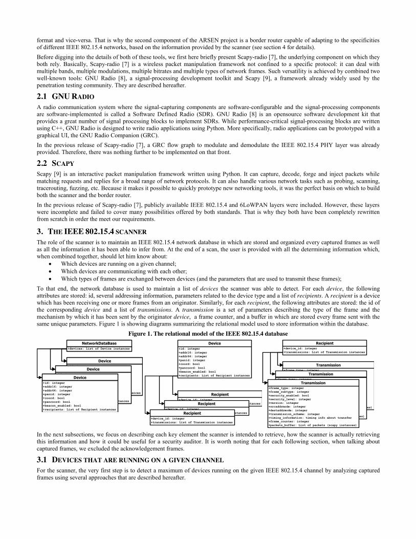
To that end, the network database is used to maintain a list of devices the scanner was able to detect. For each device, the following attributes are stored: id, several addressing information, parameters related to the device type and a list of recipients. A recipient is a device which has been receiving one or more frames from an originator. Similarly, for each recipient, the following attributes are stored: the id of the corresponding device and a list of transmissions. A transmission is a set of parameters describing the type of the frame and the mechanism by which it has been sent by the originator device, a frame counter, and a buffer in which are stored every frame sent with the same unique parameters. Figure 1 is showing diagrams summarizing the relational model used to store information within the database.
Figure 1. The relational model of the IEEE 802.15.4 database
In the next subsections, we focus on describing each key element the scanner is intended to retrieve, how the scanner is actually retrieving this information and how it could be useful for a security auditor. It is worth noting that for each following section, when talking about captured frames, we excluded the acknowledgement frames.
3.1 DEVICES THAT ARE RUNNING ON A GIVEN CHANNEL For the scanner, the very first step is to detect a maximum of devices running on the given IEEE 802.15.4 channel by analyzing captured frames using several approaches that are described hereafter.
Device+id: integer+addr16: integer+addr64: integer+panid: integer+coord: bool+pancoord: bool+beacon_enabled: bool+recipients: List of Recipient instances
Device+id: integer+addr16: integer+addr64: integer+panid: integer+coord: bool+pancoord: bool+beacon_enabled: bool+recipients: List of Recipient instances
NetworkDataBase+devices: List of Device instances
Device+id: integer+addr16: integer+addr64: integer+panid: integer+coord: bool+pancoord: bool+beacon_enabled: bool+recipients: List of Recipient instances
Recipient+device_id: integer+transmissions: List of Transmission instancesRecipient
+device_id: integer+transmissions: List of Transmission instances
Device+id: integer+addr16: integer+addr64: integer+panid: integer+coord: bool+pancoord: bool+beacon_enabled: bool+recipients: List of Recipient instances
Recipient+device_id: integer+transmissions: List of Transmission instances
Transmission+frame_type: integer+frame_subtype: integer+security_enabled: bool+security_level: integer+version: integer+srcaddrmode: integer+destaddrmode: integer+transmission_scheme: integer+timing_information: timing info about transfer+frame_counter: integer+packets_buffer: List of packets (scapy instances)
Transmission+frame_type: integer+frame_subtype: integer+security_enabled: bool+security_level: integer+version: integer+srcaddrmode: integer+destaddrmode: integer+transmission_scheme: integer+timing_information: timing info about transfer+frame_counter: integer+packets_buffer: List of packets (scapy instances)
Recipient+device_id: integer+transmissions: List of Transmission instances
Transmission+frame_type: integer+frame_subtype: integer+security_enabled: bool+security_level: integer+version: integer+srcaddrmode: integer+destaddrmode: integer+transmission_scheme: integer+timing_information: timing info about transfer+frame_counter: integer+packets_buffer: List of packets (scapy instances)

3.1.1 THE ORIGINATOR The scanner checks if it can find in the database a device sharing the same addressing information than the source addressing information of the captured frame. Note that addressing information includes the source PANId and, depending of the source address mode, the source address. When source address is missing, that means that the frame has originated from the PAN Coordinator. In this case, rather than looking for a device using its address and its PANId as an entry key, the database is requested to look for a PAN coordinator with a given PANId. If such device does not exist, a new one is registered with the appropriate information: either the couple PANId/Address or the couple PANId/PAN-Coordinator. In addition, depending on the frame type, several others information may be specified. In fact, when captured frame is a beacon, it is possible to infer the nature of the originator (PAN coordinator or coordinator) and the beacon interval if the network is a beacon-enabled one. If such device is found, it may be updated with additional potential inferred information such as the long address, the short address and the nature of the device.
3.1.2 THE RECIPIENT Note that with this approach, beacons are excluded because they do not carry any useful information for that step. The scanner checks if it can find in the database a device sharing the same addressing information than the destination addressing information of the captured frame. It is worth mentioning that addressing information includes the destination PANId and, depending of the destination address mode, the destination address. When destination address is missing, that means that the frame is directed to the PAN Coordinator. In this case, rather than looking for a device using its address and its PANId as an entry key, the database is requested to look for a PAN coordinator with a given PANId. If such device does not exist, a new one is registered by the tool with the appropriate information: either the couple PANId/Address or the couple PANId/PAN-Coordinator. If such device is found, it may be updated with additional potential inferred information such as the long address, the short address and the nature of the device.
3.1.3 THE BEACONS How the transfers are implemented depends on the network support for the transmission of beacons. A beacon-enabled PAN is used when synchronization or low-latency is required. When that is not the case, a network may not use beacons for normal transfers, but they are still required for network discovery. That is why they can be useful to gather information on a specific PAN.
3.1.3.1 THE GUARANTEED TIME SLOTS In a beaconing network, devices may request the PAN coordinator for the allocation of a Guaranteed Time Slot (GTS). A device can infer that it actually owns a GTS if its address is contained in the GTS fields of the periodic beacons. The scanner is able to recover the addresses of the GTS owners by simply reading the corresponding fields of the captured beacons. The PANId of each GTS owner is inferred from the beaconing coordinator’s PANId. Both the addresses and the PANId being retrieved, the scanner can register the new devices in the database. If a device is already registered in the database, the scanner does nothing. It is worth noting that, such a mechanism cannot be processed by the scanner if beacon payloads are encrypted.
3.1.3.2 THE PENDING ADDRESSES When a coordinator wishes to transfer data to a device in a beacon-enabled PAN, it may use three types of transmission models and among them the indirect one. In an indirect transmission scheme, the coordinator maintains in its periodic beacons a list of device addresses for which data are pending, and wait for the corresponding devices to request the data. The scanner takes advantage of this feature to infer the presence of devices on the network. Each time a beacon is captured, the pending addresses field is read and new devices can be registered in the database. Note that for each discovered address, the PANId is inferred from the corresponding coordinator PANId. If a device is already registered in the database, the scanner does nothing.
3.1.4 THE ASSOCIATION PROCEDURE Each IEEE 802.15.4 device owns a unique 64-bit extended address but a 16-bit short address may also be allocated by the coordinator when the device associates. Both of these two addresses may be used for transmission within the network. However, there is no way to make the connection between the short address and the long address owned by a single device, except when capturing an association procedure. In fact, during such procedure, the device asks the coordinator to associate with the PAN and, optionally, requests a short address. If the coordinator was able to associate the device to its PAN and allocate a short address, it will reply with an association response command frame that contains the allocated short address.
3.1.4.1 DEVICE ADDRESSES As the IEEE 802.15.4 standard states that the coordinator shall use the 64-bit extended address of the device requesting for association as the destination address of its association response frame, the scanner is able to retrieve, by simply reading the corresponding fields of this frame, both the short and the long address the device owns. The two addresses being retrieved, the scanner checks whether or not the discovered device had already been registered in the database as two distinct device instances, one with the short address and the other with the long address. In such a case, it simply merges the two instances. If the scanner can only find in the database a single registered device instance in which only one of the two retrieved addresses are known, it feeds it with the other. If no devices are found, it simply instantiates a new one with the two addresses it just retrieved. Finally, if the scanner finds a device in which both the short and the address are known, it does nothing.
3.1.4.2 COORDINATOR ADDRESSES When sending beacons, a coordinator may choose between its short and its long address as a source address. When sending data or command frames, it may use another addressing mode than it actually uses for beacon transmission. The coordinator association response

command is part of the association procedure and informs the device wishing to join the PAN whether or not its request has been accepted. When capturing such a frame, if the scanner identifies that the source addressing mode is not the same as the one used for beacons, it can make the connection between the long and the short address owned by the coordinator. The database is then updated accordingly. The two addresses being retrieved, the scanner checks whether or not the coordinator had already been registered in the database as two distinct device instances, one with the short address and the other with the long address. In such a case, it simply merges the two instances. If the scanner only find in the database a single registered device instance in which only one of the two retrieved addresses are known, it feeds it with the other. Finally, if the scanner finds a device in which both the short and the address are known, it does nothing.
3.2 DEVICES THAT ARE COMMUNICATING WITH EACH OTHER Being aware of each pair of devices communicating on the network can be very useful, especially when spoofing devices. Moreover, from this information, the network topology may be retrieved. For each captured frame in which the frame-type subfield does not specify an acknowledgment or a beacon frame, the scanner retrieves information about the originator and the expected recipient by analyzing both the source and the destination addressing fields. After ensuring both devices were registered in the database, the receiving device is, if that is not already the case, stored as a recipient in the originator instance. The mechanism by which the transmission parameters are stored is detailed in next section.
3.3 TYPES OF FRAMES THAT ARE EXCHANGED BETWEEN DEVICES In this section, we focus on describing the transmission parameters that can be inferred from captured frames:
x Frame type and subtype; x Addressing modes; x Data transmission model; x IEEE 802.15.4 standard version; x Security policy;
For each captured frame in which the frame-type subfield does not specify an acknowledgment or a beacon frame, the scanner stores in the database the parameters used by the originator to transmit the frame. This is achieved by instantiating a transmission object and adding it to the recipient of the corresponding originator instance. A transmission object contains a list of parameters, a frame counter and a buffer in which are stored every captured frames that have been sent with these parameters. When dealing with a captured frame, is the scanner identifies that in the database the pair originator/recipient already exists and, that the transmission parameters are already known, it does not create a new transmission instance but rather increments the counter of the corresponding instance and stores the packet in the buffer. Moreover, for each captured frame, the scanner first checks if both originator and recipient devices exist and instantiate them otherwise. It is worth noting that, most part of the parameters listed below can be retrieved regardless of the use of security. However, when guessing the security policy which has been used to secure a captured frame, the scanner requires the user to provide an encryption key.
3.3.1 FRAME-TYPE AND SUBTYPE Knowing about each frame-type (and subtype when it is a command frame) a device has been able to send/receive during the scan can give clues about how important are devices. Also, it can help an auditor to choose which device to spoof when wishing to send a specific frame-type/subtype to a given recipient, ensuring a normal behavior. The scanner retrieves the frame-type and, when necessary, the frame-subtype by simply reading the corresponding fields of the given frame.
3.3.2 ADDRESSING MODES To be sure an outgoing frame would not be rejected by a device because of the use of an improper addressing mode, it is interesting to retrieve, for each captured frame, which addressing modes have been used. Thus, the auditor would know which source and destination addressing modes to use in order to send a secured data frame to device B, while mimicking device A. As for the frame-type and subtype, the scanner retrieves both source and destination addressing information by simply reading the corresponding fields of the given frame.
3.3.3 DATA TRANSMISSION MODEL Depending on the network’s ability of transmitting periodic beacons (beacon-enabled PAN) and on device types, numerous transfer models can be used by devices to transfer data frames. Retrieving the mechanism by which each pair of devices communicates can guide the auditor in his choice of a transfer scheme when trying to send data to a given device. The available transfer models are described hereafter.
3.3.3.1 BEACON-ENABLED PAN 3.3.3.1.1 DEVICE TO COORDINATOR (OR PAN COORDINATOR) If the device has been allocated a transmission Guaranteed Time Slot (GTS) by the coordinator, then it will directly transmit the data frame during its reserved slot during the Contention Free Period (CFP). The scanner always stores the last captured beacon. When a data frame is received and is directed to the beaconing coordinator, it checks in the GTS subfield of the beacon MAC field if a GTS is actually allocated to the originator device. If so, the scanner infers that the given frame has been sent according to a GTS scheme. It is worth noting that, however, even if a device owns a transmission GTS, it still can send its data frame using direct transmission during the Contention Access Period (CAP). Having said that, this information is still available and ensures the user that, by following a GTS transmission model, the frame he wants to send will not be rejected. Moreover, in order to let the user know which slot(s) the originator owns, the scanner stores the following timing information: beacon order, superframe order, final CAP slot as well as the GTS starting slot and the GTS length of the corresponding device, everything being available in the beacon.
When no transmission GTS has been found for the originator in the GTS field of the beacon frame, in a direct transmission scheme, the device wishing to send data to its coordinator will first synchronize with beacons and then send its frame during the Contention Access Period (CAP).
3.3.3.1.2 COORDINATOR (OR PAN COORDINATOR) TO DEVICE If the recipient device had previously been allocated a GTS for reception by the coordinator, then the coordinator will thus directly transmit its data frame during the corresponding slot(s). When a data frame is received and has originated from the beaconing coordinator, the scanner checks in the GTS subfield of the most recent beacon’s MAC field if a GTS is actually allocated to the recipient device. If so, the scanner infers that the captured frame has been sent according to a GTS scheme. This information ensures the user that, by following a GTS transmission model, the frame he wants to send will not be rejected by the recipient. Note that, however, even if a device owns a reception GTS, a coordinator can still send data to it using direct transmission. In this scenario, the scanner stores timing-related information to situate the exact position of the slot(s) the device owns. This information are: beacon order, superframe order, final CAP slot as well as the GTS starting slot and the GTS length of the corresponding device, everything being available in the beacon. In this case, the coordinator indicates in its periodic beacons that data are pending. The target device then requests the pending data by sending a MAC data request command. Finally, the coordinator sends the data frame during the CAP. For each captured data frame, the scanner can infer that an indirect transmission scheme has been used if the recipient has been sending a data request command just before receiving the data frame. When neither the GTS transmission mechanism nor the indirect transmission mechanism has been identified, the coordinator will send its frame directly during the CAP.
3.3.3.2 NONBEACON-ENABLED PAN 3.3.3.2.1 DEVICE TO COORDINATOR (OR PAN COORDINATOR) In a nonbeacon-enabled PAN, devices have no choice but to directly send their data frames to their coordinators. Thus, there is no need to compute anything.
3.3.3.2.2 COORDINATOR (OR PAN COORDINATOR) TO DEVICE Just as in a beacon-enabled PAN, the coordinator stores the message it wants to send and waits for the concerned device to request the data. However, in this case, the coordinator is not sending any beacons and thus cannot indicate that data are pending. This is the device itself which, at a software defined rate, sends data request commands. On reception of such a command and if data are actually pending for the requesting device, then the coordinator first sends an acknowledgment in which the frame pending bit is set to one and then sends the data frame. For each captured data frame, the scanner can infer that an indirect transmission scheme has been used if the recipient has been sending a data request command just before receiving the data frame. When the indirect transmission mechanism has not been identified, then the coordinator directly sends its data frame to the recipient device
3.3.4 VERSION OF THE IEEE 802.15.4 STANDARD Since its initial release in 2003, the IEEE 802.15.4 standard has been revised two times. In this project, we only focused on the 2003 and the 2006 versions of the standard as the 2011 version does not affect any features we implemented in the scanner. Thus, from the scanner point of view, there are only two possibilities: 2003 and 2006 or higher. Moreover, the IEEE 802.15.4-2006 standard states that, excluding two minor cases, all unsecured frames are compatible with IEEE 802.15.4-2003 standard. However, it also stipulates that secured frames are differently formatted and thus incompatible. When this is the case, a 2-bit field called frame-version is set to 0x1 in the corresponding frame. Thus, when dealing with such version-specific frames, the auditor needs to infer the version of the standard they are compliant with before trying to manipulate them. On that aspect, the scanner retrieves, when necessary (i.e., when security is enabled), the frame version simply by reading the corresponding fields of the given frame.
3.3.5 SECURITY POLICY As explained before, depending on the standard version the secured frames are compliant with, they are formatted in a different manner. In this section we first describe here the low-level security mechanism for both 2003 and 2006 versions of the standard and then we explain how the scanner can, to a certain extent, infer the security policy which has been used by the originator to secure each captured frame.
3.3.5.1 IEEE 802.15.4-2003 SECURITY POLICIES In IEEE 802.15.4-2003 standard, frames can be secured according to three transformation processes: CTR, CBC-MAC or CCM. CCM is block cipher mode combining the CTR encryption mode with the CBC-MAC authentication mode, providing both encryption and authentication. As for the IEEE 802.15.4 standard, the block cipher shall be the advanced encryption standard (AES)-128. CBC-MAC and CCM can be leveraged such as they can provide each one three levels of data authenticity (MIC-32, MIC-64 or MIC-128). While CBC-MAC provides nothing but authenticity, CTR and CCM always provide confidentiality. In all, IEEE 802.15.4-2003 standard provides seven security levels to protect frames. Contrary to the IEEE 802.15.4 standard, secured frames compliant with the IEEE 802.15.4-2003 standard do not include in their header any information about which security protection has been processed by the originator. Thus, devices must know in advance which security policies are used by all devices. CTR and CCM require a 13-octets sized nonce to perform security. It is formatted as the combination of the extended source address, the frame counter and the key sequence counter, a counter which can be used, for instance, when the frame counter is exhausted. Of course, both the originator and the recipient devices shall use the same nonce. Thus, each outgoing secured frames shall include in their header the frame counter and the key sequence counter formerly used by the originator to secure the frame.

3.3.5.2 IEEE 802.15.4-2006 SECURITY POLICIES The IEEE 802.15.4-2006 standard states that frames shall be secured according to the transformation process known as CCM*. It is a generic combined encryption and authentication bloc cipher mode. The standard also specifies that the block cipher to be used is the advanced encryption standard (AES)-128. CCM* can be leveraged such as it can provide up to seven kind of frame protection, allowing for varying levels of data authenticity and for optional data confidentiality. In order to the recipient device to know which unsecuring process to perform, all outgoing secured frames shall provide in their header the proper security level used by the originator to protect the frame. CCM* also requires a nonce to process security. The nonce is a 13-octets string and is formatted as the combination of the extended source address, the frame counter and the security level. As for the security level, each outgoing secured frame shall provide in its header the frame counter which has been used by the originator during the securing process. Note that the extended addresses do not have to be included in secured frames because they may have been retrieved by recipient devices in previous transfers, making them able to infer the extended addresses from the short ones.
3.3.5.3 SECURITY POLICY IDENTIFICATION As explained before, in the IEEE 802.15.4-2006 standard, the security policy used for protecting a frame is indicated in the header of the concerned frame through the value of the security level field. Thus, when dealing with such frames, the scanner just have to read the corresponding field to retrieve the security policy. The security level is then added as a parameter in the corresponding transmission instance. As for the IEEE 802.15.4-2003 standard, security level by which a frame has been secured is not provided to the recipient. In fact, the device shall know in advance which unsecuring process to use. When such a frame is captured, the scanner does nothing but storing the frame in the database, either in an appropriate existing transmission instance or in a new one. However, at the end of a scan, if requested by the user, the scanner will try to unsecure the frames for transmission instances that specify that security was enabled. If appropriate, the scanner will also try to guess the security policy in the process. The steps used to unsecure frames are the following:
x The scanner first asks the user to provide an encryption key. Then, it tries to unsecure the buffered frames (a maximum number can be defined by user), using every security policy of the IEEE 802.15.4-2003 standard if the frame-version parameter specifies an IEEE 802.15.4-2003 frame or using the single IEEE 802.15.4-2006 security policy specified by the value of the security-level parameter stored during the scan.
x When a decrypted payload appears to be a valid one (either the header of a valid higher layer protocol is recognized or a low entropy is computed), and/or a MIC can be recovered, a parameter called security-found is set to true in the transmission instance. If the frame-version parameter of the transmission instance specifies IEEE 802.15.4-2003 frames, the retrieved security-level is also added as a parameter.
x For both frame-versions, if the security policy could not have been found, the security-found parameter shall be set to false.
3.3.5.4 SECURITY POLICY DEVIATION We argue here that, because when a PAN is designed usually all the network components rely on the same hardware and software, it makes it possible for a deviation from the standard to slip through and stay unnoticed for as long as it does not disrupt availability and efficiency. This is even true when multiple PANs are connected to a grid since the border routers used for interconnection are likely to rely on the same faulty components. Usually, they are unintentional mistakes affecting low-level security mechanisms. Sometimes, they originate from a mix-up between different revisions of the standard. The scanner can detect a number of deviations (based on actual deviations we observed during several security audits). When the security policy of a transmission instance cannot be identified, the user may request the scanner to look for any of the deviations it supports. They are listed at the end of this subsection (they are all identified by a unique id by the scanner). A user can choose one or several deviations he wants the scanner to look for. Moreover, as a network may include several deviations, the user should also configure the number of simultaneous deviations the scanner is intended to look for. At the end of this process, taking into account the deviations the user requested the scanner to check, if a payload appears to be a valid one, the security policy is considered to be found and the corresponding transmission instance is updated with both the ids of the discovered deviations and the setting of the security-found attribute to true. However, if the security policy could not have been retrieved, no parameters are added in the corresponding instance (the security-found attribute already set to false). Deviations regarding the IEEE 802.15.4-2003 standard
x (CTR) The nonce used is the 2006 standard’s one (Source Address + Frame Counter + Security level rather than Source Address + Frame Counter + Key Sequence Counter).
x (CTR) Flag octets of input blocks are not set to 0b10000010 but to another value; x (CTR) The first block counter used for encryption is equal to 0x0001 and not 0x0000; x (CBC-MAC) Tag T is obtained by keeping the rightmost M bytes of the last computed CBC-MAC value rather than the leftmost
M bytes; x (CBC-MAC) The length field of the first input block used to generate the key streams is not equal to (n + m) but to (n + m + 1); x (CCM Authentication) The nonce used is the 2006 standard’s one; x (CCM Authentication) Flag octet of the first input block B0 is not set to the value specified in the standard;

x (CCM Authentication) The string encoding the additional string a is formed by concatenating l(a) (the length in octet of a) within 2 octets with a itself, but is not padded with zeros so that its length is divisible by 16;
x (CCM Authentication) The authentication tag T is not obtained by keeping the first-M-octet of the last output block but by keeping the last M-octet;
x (CCM Encryption) The nonce used is the 2006 standard’s one; x (CCM Encryption) Flag octet of the input counter blocks is not formatted as specified in the standard; x (CCM Encryption) First counter block used to generate the first key stream block (to encrypt/decrypt message) is not A1 but A0; x (CCM Encryption) Encrypted tag U is generated by XORing the authentication tag T with the last key stream blocks (Sn) rather
than the first key stream blocks (S0); x (CCM Encryption) Encrypted tag U is generated by XORing the authentication tag T with the key stream blocks S1 rather than
S0; Deviation regarding the IEEE 802.15.4-2006 standard
x (CCM*) Security policy is not the same as indicated in the auxiliary security header; x (CCM*) When transforming inputs before performing the CCM* mechanism, the encoded a data is not right-concatenated with
zeros so that the octet string has length divisible by 16; x (CCM* Authentication) Flag octet of the first input block B0 is not set to the value specify in the standard; x (CCM* Authentication) Tag T is obtained by keeping the rightmost M bytes of the last computed CBC-MAC value rather than
the leftmost M bytes; x (CCM* Encryption) Flag octets of the input counter blocks are not formatted as specified in the standard; x (CCM* Encryption) The counter block used to generate the first key stream block (to encrypt/decrypt message) is not A1 but A0; x (CCM* Encryption) Encrypted tag U is generated by XORing the authentication tag T with the last key stream blocks (Sn) rather
than the first key stream blocks (S0); x (CCM* Encryption) Encrypted tag U is generated by XORing the authentication tag T with the key stream blocks S1 rather than
S0; Deviation regarding the version of the standard itself
x The Frame version subfield of the frame specifies a 2006 frame but is a 2003 one; x The Frame version subfield of the frame specifies a 2003 frame but is a 2006 one; x The frame is a 2003-frame but is secured with a 2006 standard’s security policy; x The frame is a 2006-frame but is secured with a 2003 standard’s security policy;
4. THE 6LOWPAN BORDER ROUTER The role of the border router is to translate incoming and outgoing frames from and to the 6LoWPAN format. Moreover, it must be able to do so while adapting to the specificities of the underlying IEEE 802.15.4 infrastructure. In the following sections, we assume that such specificities are provided by the IEEE 802.15.4 scanner but that is not a mandatory step: it might as well be manually provided based on some other source of information.
4.1 IEEE 802.15.4 AND 6LOWPAN 6LoWPAN is an IPv6-based low-power wireless personal area network which is composed of devices compliant with the IEEE 802.15.4 standard. Before ensuring IPv6 transmission over such a wireless protocol, several issues need to be solved, and among them the very limited size of IEEE 802.15.4 packets. Indeed, while the MAC MTU size of an IEEE 802.15.4 packet is 127, the MTU size of an IPv6 packet is 1280. Adding a maximum frame overhead of 25 bytes leaves only 102 bytes available for handling IPv6. Moreover, the use of security introduces further overhead, up to 21 bytes in IEEE 802.15.4-2003 and up to 30 bytes in IEEE 802.15.4-2006. Furthermore, as the IPv6 header is 40 octets long, the remains payload for higher protocol such as UDP and TCP are very limited. To solve the exposed issues, an adaptation layer has been specified between the MAC layer and the IP network layer and is part of the 6LoWPAN protocol. It handles both fragmentation and reassembly of IPv6 packets, while providing a header compression scheme to reduce the size of the IPv6 header and, when necessary, the UDP header. Also, as described later, the specification supports mesh routing mechanisms.
4.2 VIRTUAL NETWORK INTERFACE To allow communications between our border router and the host, we used a virtual network kernel device known as TUN. It operates on layer 3 and delivers all the packets sent by an operating system to attached user-space programs. Conversely, user-space packets passed to the TUN are forwarded to the operating system. Actually, our router has been implemented as a user-space program while the operating system represents the IP-based tools a security auditor would use (nmap, telnet, ping, etc.). Thus, in the operating system point of view, our tool is considered as an external source. As TUN interfaces operate on layer 3, only the IPv6 layer of packets are forwarded, allowing our tool to not care about Ethernet. It thus does not have to deal with MAC addresses when communicating with the host. Note that it still needs an IEEE 802.15.4 MAC address to communicate with the wireless network.
4.3 NETWORK CONFIGURATION In this section we just provide details about how the router’s addressing information are handled when wishing to transmit frame over the air. We assume that the user would like to either spoof an existing device or act as a third device on the network. In the former case, the user will be invited to enter both an IPv6 address and a link-layer address (a 16-bit short address and/or a 64-bit extended address). It is worth noting that, some established network will not allow a new device to communicate on the PAN if not associated. To solve this issue, we implemented a procedure which handles association procedure within a PAN. However, as a PAN could maintain a kind of ACL, it is possible that association procedures will be rejected. In this case, we advise the user to user the spoofing method. In the latter case, namely the spoofing method, user will be requested by the router to provide both the IPv6 address and at least one link layer address of the existing device he wants to spoof. To ensure efficient communications within the network, we also recommend the user to use the IEEE 802.15.4 scanner we developed in order to configure the router such as it uses the proper transmission scheme as well as the proper security policy. Note that for the security policy, the user will be requested by the scanner to provide one or several encryption key for each pair of devices communicating on the network. Please refer to section 4.4.4 to know how to deal with recipient link layer addressing information.
4.4 IPV6 TO 6LOWPAN Here we explain how incoming IPv6 packets are handled by the router before being transmitted over the air.
4.4.1 IPV6 HEADER COMPRESSION PDU size of an incoming IPv6 packet is checked to ensure it is not greater than the MTU size of IEEE 802.15.4 packets. If it exceeds this limit, the IPv6 header is compressed following the encoding scheme specified in the RFC 6282. The result is known as the LOWPAN_IPHC, a 13-bit field IPv6 compressed header. This field is always preceded by a 5-octets flag indicating that the following field is actually the LOWPAN_IPHC field itself. By relying on several common rules, the encoding mechanism tries to elide, either literally or partially, the IPv6 header fields which can be inferred by the recipient device. Each field that could not have been elided is carried in-line right after the LOWPAN_IPHC header, either in a compressed form if it has been partially elided or literally. Note that, in this case, they appear in the same order as they do in the uncompressed IPv6 header. The rules that the encoding mechanism relies on are assumed to be common on the 6LoWPAN network and are listed below:
x Version is 6; x Traffic class and Flow label are both zero; x Payload length can be inferred from lower layers; x Hop limit is set to a well-known value (1,64 or 255); x IPv6 addresses are formatted using the link-local prefix or a small set of well-known routable prefixes; x IPv6 addresses are partly constructed from either the 64-bit extended or the 16-bit short IEEE 802.15.4 addresses;
When Multicast IPv6 addresses are used, a special scheme is to be performed. A multicast address is formatted as the combination of an all ‘1’ 8-bit prefix, indicating that the address is actually a multicast address, a 4-bit flag field, giving multiple information about the address, a 4-bit scope field, indicating the scope in which the address is valid and a 112-bit group ID, indicating a group within the given scope. All IPv6 multicast addresses where the upper layer of the multicast group identifier are zero may be compressed down to 48 or 32 bits. In such cases, only the flag, the scope and the least-significant bits of the multicast group identifier are carried in-line. Another special multicast address known as Solicited-Node Multicast address may be compressed down to 8-bit. Its format is such as only its least-significant group ID is to be carried in-line. Furthermore, when dealing with multicast addresses, two LoWPAN headers also have to be added, the LoWPAN Mesh addressing and the Broadcast/Multicast headers. This is discussed on specific sections. Moreover, the mechanism allows network’s devices to use up to 16 context identifiers to encode source addresses and up to 16 others context identifiers to encode destination addresses. When contexts are used, the LOWPAN_IPHC is extended with a further Context ID field formatted as a 4-bit source Context ID and a 4-bit destination Context ID. RFC 6282 also defines a compression format for IPv6 extensions and UDP headers. However, we only focused on UDP header compression, handling IPv6 extensions by carrying them in-line. When the next header field of the IPv6 header specifies the UDP protocol, it is fully elided. Furthermore, as stated before, the header of such a protocol shall be compressed according to the encoding scheme specified in the RFC 6282. A special section is dedicated to the UDP header compression. In the best case, i.e. every IPv6 header fields could have been fully elided and no context are used, the IPv6 header can be compressed down to 2-octets formatted as the 5-bits flag octet and the 13 bits LOWPAN_IPHC compressed header, without any further field carried in-line. Note that, to perform the IPv6 header compression, the router needs to retrieve the IEEE 802.15.4 addressing information of the device the user wants to communicate with. We discuss this process in a special section (NDP TABLE). If at the end of the compression process the IPv6 packet meets the IEEE 802.15.4 MTU size constraint (taking into account the use of the security), the packet can be encapsulated and sent over the air. Otherwise, the packet will need to be fragmented. The mechanism is described in a specific section.

4.4.2 UDP HEADER COMPRESSION RFC 6282 states that UDP header, when present, shall be compressed. The result is known as the LOWPAN_NCH compressed header formatted as a 5-bit pattern specifying an UDP header compression and 3 others bits used for UDP checksum and UDP ports compression. The UDP checksum can be fully elided on condition that another integrity check mechanism providing at least the same information than the UDP checksum is contained in the UDP payload (IPSec when using IP over UDP tunneling or MIC within UDP payload). Additionally, another lower-layer integrity check mechanism (i.e. IEEE 802.15.4 Message Integrity Code (MIC)) must be provided to ensure the detection of pseudo header corruption. If these conditions are not meet, the checksum cannot be compressed. To ensure a device will not reject our frames because of the absence of the UDP checksums, the router never elides this field. The UDP ports can also be partially elided if they are contained in small ranges of values. A specific compression scheme is applied when both the source and the destination ports are contained in the range 0xf0b0 – 0xf0bf while another one is applied for each port if it is contained in the range 0xf000 – 0xf0ff. In the former case, first 12 bits of both source and destination ports are elided while the remaining 4 bits of both ports are carried in-line. In the latter case, the first 8-bits of each port meeting the constraint are elided while the remaining 8 bits are carried in-line. When neither the first nor the second case is met, ports are fully carried in-line. For UDP ports compression, we simply followed the scheme we described above. Fields or subfields which are to be carried in-line are placed right after the LOWPAN_NCH header, in the order in which they appear in the uncompressed UDP header.
4.4.3 FRAGMENTATION If an IPv6 packet does not fit within a single IEEE 802.15.4 frame, it shall be fragmented according to the process specified in the RFC 4944. The IPv6 frame could be either a frame whose header compression did not reduce the frame size enough to meet the IEEE 802.15.4’s MTU size constraint or an uncompressed IPv6 frame. The fragmentation process consists of breaking the IPv6 frame into multiple link-layer fragments. The first fragment is called the first fragment while the others are called the subsequent fragments. The first one shall be formatted as the combination of a 5-bits flag, indicating that the following fields are part of the first fragment, an 11-bits datagram size, encoding the size of the entire IPv6 frame before fragmentation, and a 16-bits datagram tag, a unique identifier of the IPv6 packet being fragmented. The subsequent fragments are formatted as the combination of a 5-bits flag, indicating that the following fields are part of a subsequent fragment, the datagram size, the datagram tag and the datagram offset, specifying the offset, in increments of 8-octets, from the beginning of the IPv6 payload before fragmentation. As the fragment offset can only express multiples of eight bytes, the size of all link fragments for a given Ipv6 packet except the last one shall be multiples of eight bytes. Our router performs fragmentation just as it is specified in the RFC 4944. Once the IPv6 frame has been fragmented and all the fragments have been encapsulated, they are sent over the air in the proper order such as the recipient can reconstruct the original frame.
4.4.4 NPD TABLE When wishing to send an IPv6 frame over the air, the router needs to know which link layer destination address to use, especially when dealing with IPv6 addresses compression. If the user chose to use the IEEE 802.15.4 scanner we introduced in the very first part of this document, the router would be able, at a certain extent, to retrieve this information in the database automatically generated by the scanner. Otherwise, the router will send a NDP request frame in broadcast and wait for response. As remote devices may not always support the NDP protocol, if at the end of this process the addressing information could not have been retrieved, the IPv6 destination address will not be compressed and the frame will be sent over the air using the broadcast IEEE 802.15.4 address (0xffff). Note that, when starting the router, user can also provide the router with a python dictionary in which the keys are the IPv6 addresses and the values are the corresponding link-layer addresses. Once the IEEE 802.15.4 addresses are retrieved, whatever how, they are stored in a kind of NDP table that aims at helping the router in future communications.
4.4.5 MESH ROUTING In a mesh topology, an originator may request intermediate devices to forward its outgoing frame towards the final destination. The RFC 4944 states that, in such a case, the frame shall include a mesh addressing header. This field is formatted as the combination of a 2-bits flag, indicating that the following fields are part of the mesh addressing header, a 1-bit field indicating if the originator has been using its 16-bit short or 64-bit extended address, another 1-bit field indicating if the final destination address is a 16-bit short or a 64-bit extended address, a 4-bit hop limit and both the originator and the final destination addresses, formatted as indicated in the previous fields. When detecting such a header, an intermediate device would consult its routing table and replace both the source and the destination addresses of the link layer by its IEEE 802.15.4 address and, regarding the routing table response, either the final destination or another intermediate IEEE 802.15.4 address, respectively. Concerning the mesh addressing header, the hop limit is decremented by one while the others fields are left unchanged such as it can be used by another intermediate device to forward the packet. When receiving an IPv6 frame from the TUN, the router has to deal with such a routing table. It has to send the frame to the proper intermediate device such as the frame can be forwarded towards the final destination the user were trying to reach. If the scanner has been provided with the database our IEEE 802.15.4 scanner is intended to generate, the router would be able, at a certain extent, to retrieve this
information. In fact, we added a mechanism in the scanner that aims at retrieving the routing path for each pair of 6LoWPAN devices communicating on the network. If the path could not have been retrieved, the frame is sent by using the mesh addressing header with the proper originator and final destination addresses anyway but the link layer destination address would be the broadcast address (0xffff).
4.4.6 BROADCAST / MULTICAST IEEE 802.15.4 does not natively support multicasting. Thus, IPv6 multicast frames shall be handled as link-layer broadcast packets in IEEE 802.15.4 networks. To do so, the link-layer destination PANID shall be set to the proper value, such as it matches the PAN ID of the corresponding link. Moreover, the link layer destination address shall be the 16-bit short broadcast address (0xffff). By this way, it ensures that multicasting will be handled by the right upper layer. Note that multicasting is only supported only on mesh networks. Thus, each IPv6 multicast frames will always be encapsulated with the mesh addressing header, the header we described on section 9. It will also be encapsulated with a broadcast header known as LOWPAN_BC0 in the RFC 4944, right after the mesh addressing header. It is formatted as the combination of an 8-bits flag, indicating that the next fields are part of the broadcast header, and an 8-bits sequence number, used for detecting duplicated packet. When our tool detects an IPv6 frame whose destination address is a multicast address, we simply add both the mesh addressing and the broadcast headers before sending it in broadcast (link-layer point of view) on the proper PANID.
4.4.7 SUPPORTED FEATURES So we could describe some of the main features the router was supporting. Most part of them are directly derived from both the RFC 4944 and the RFC 6882 while others like the NDP table we implemented are used to improve the tool behavior in an auditing point of view. We could see that they were actually up to six adaptation layer headers which can be added to the IPv6 frame to enable its transmission over IEEE 802.15.4. Note that, when several LOWPAN headers are used in the same packet, they shall appear in the following order:
x Mesh addressing header x Broadcast header x Fragmentation header (First or subsequent) x Compression header (IPv6 compressed header and/or Next Header compressed header)
Remember that when compressing IPv6 header and Next header, each field which could not have been full elided are carried in line, either in a compressed form or literally. Also remember that when carried in-line, fields or subfield appear in the same order as they do in their corresponding uncompressed header.
4.5 6LOWPAN TO IPV6 Here we explain how incoming 6LoWPAN packets are handled by the router before being transmitted to the “computer” through the TUN. Note that the scanner will not care about frames that are not indicating its link level address (the IEEE 802.15.4 address the user chose when starting the router). We assume in the following section that the link layer destination address is actually the router one.
4.5.1 MESH ROUTING When capturing a 6LoWPAN frame whose first header’s flag indicates a mesh addressing header, the tool first check if the frame is directed to it by checking the final destination field of the mesh addressing header. If so, the corresponding header is removed and next headers are handled. If no header follows the mesh addressing header, the frame is directly transmitted to the TUN just after ensuring the IPv6 destination address was the router one. If the scanner infers that the frame does not indicate it as a recipient, by checking both the final destination and the IPv6 destination address, the frame is simply rejected.
4.5.2 BROADCAST / MULTICAST After having removed the mesh addressing header, if a Broadcast header is present (i.e. the header’s flag indicating a broadcast header), it is simply removed and next headers are handled. If no further headers are present, and if the IPv6 multicast address indicates a group ID in which router is included, the packet is transmitted to the TUN. Otherwise, if the router is not indicated as a recipient, the frame is rejected.
4.5.3 FRAGMENT REASSEMBLY When detecting a 6LoWPAN first fragment packet, the router stores it and waits for the following subsequent packets to be captured. When all frames are captured, the frame is reassembled. Then, the next headers of the reconstituted packet are handled. If no further headers are present and if the IPv6 address indicates an IPv6 address that match its address, the packet is transmitted to the TUN. Otherwise, if the IPv6 destination address is not the one of the scanner, the packet is rejected.
4.5.4 HEADERS DECODING If a compressed IPv6 header is detected, the frame is uncompressed to retrieve the real IPv6 header. If, while handling the IPv6 compressed header, the scanner sees that the next header is a compressed UDP header, it also tries to retrieve the real UDP header. At the end of this process, if the retrieved IPv6 destination address is not the one of the scanner, the packet is rejected. Otherwise, the frame is transmitted to the TUN.
5. IEEE 802.15.4 ATTACKS The 6LoWPAN protocol can rely on the security mechanisms offered by the IEEE 802.15.4 standard at the MAC-sublayer level. In this section, we focus on known attacks that affect the IEEE 802.15.4 standard. It is worth mentioning that we will not consider attacks that only impact availability [6] because, even if they could be prevented, in the end, a determined malicious individual could still resort to radio-based PHY jamming attacks. That means that we will focus on attacks that can impact confidentiality or integrity.
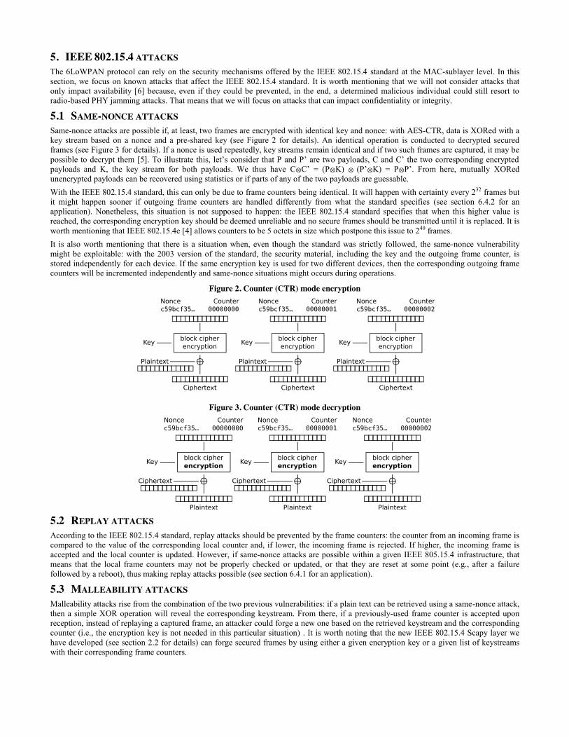
5.1 SAME-NONCE ATTACKS Same-nonce attacks are possible if, at least, two frames are encrypted with identical key and nonce: with AES-CTR, data is XORed with a key stream based on a nonce and a pre-shared key (see Figure 2 for details). An identical operation is conducted to decrypted secured frames (see Figure 3 for details). If a nonce is used repeatedly, key streams remain identical and if two such frames are captured, it may be possible to decrypt them [5]. To illustrate this, let’s consider that P and P’ are two payloads, C and C’ the two corresponding encrypted payloads and K, the key stream for both payloads. We thus have C⊗C’ = (P⊗K) ⊗ (P’⊗K) = P⊗P’. From here, mutually XORed unencrypted payloads can be recovered using statistics or if parts of any of the two payloads are guessable. With the IEEE 802.15.4 standard, this can only be due to frame counters being identical. It will happen with certainty every 232 frames but it might happen sooner if outgoing frame counters are handled differently from what the standard specifies (see section 6.4.2 for an application). Nonetheless, this situation is not supposed to happen: the IEEE 802.15.4 standard specifies that when this higher value is reached, the corresponding encryption key should be deemed unreliable and no secure frames should be transmitted until it is replaced. It is worth mentioning that IEEE 802.15.4e [4] allows counters to be 5 octets in size which postpone this issue to 240 frames. It is also worth mentioning that there is a situation when, even though the standard was strictly followed, the same-nonce vulnerability might be exploitable: with the 2003 version of the standard, the security material, including the key and the outgoing frame counter, is stored independently for each device. If the same encryption key is used for two different devices, then the corresponding outgoing frame counters will be incremented independently and same-nonce situations might occurs during operations.
Figure 2. Counter (CTR) mode encryption
Figure 3. Counter (CTR) mode decryption
5.2 REPLAY ATTACKS According to the IEEE 802.15.4 standard, replay attacks should be prevented by the frame counters: the counter from an incoming frame is compared to the value of the corresponding local counter and, if lower, the incoming frame is rejected. If higher, the incoming frame is accepted and the local counter is updated. However, if same-nonce attacks are possible within a given IEEE 805.15.4 infrastructure, that means that the local frame counters may not be properly checked or updated, or that they are reset at some point (e.g., after a failure followed by a reboot), thus making replay attacks possible (see section 6.4.1 for an application).
5.3 MALLEABILITY ATTACKS Malleability attacks rise from the combination of the two previous vulnerabilities: if a plain text can be retrieved using a same-nonce attack, then a simple XOR operation will reveal the corresponding keystream. From there, if a previously-used frame counter is accepted upon reception, instead of replaying a captured frame, an attacker could forge a new one based on the retrieved keystream and the corresponding counter (i.e., the encryption key is not needed in this particular situation) . It is worth noting that the new IEEE 802.15.4 Scapy layer we have developed (see section 2.2 for details) can forge secured frames by using either a given encryption key or a given list of keystreams with their corresponding frame counters.

6. TYPICAL APPLICATION In this section, we talk about a penetration test that we conducted, relying on the ARSEN tools, on a wireless communication infrastructure dedicated to the monitoring of a water distribution network system (see Figure 4). The goal of this infrastructure was to capture information about multiple continuous water pipes by means of electrochemical and optical sensors. It is worth noting that the sensors were powered by microturbines embedded within the water pipes. The objective behind this infrastructure is to provide useful information to field technicians and to supply a large volume of data to a distributed water management system. On that aspect, the wireless communication relied on the IEEE 802.15.4 standard to build a star network and on the 6LoWPAN and UDP protocols to transport the actual information.
Figure 4. Two smart sensors from the wireless monitoring infrastructure
As previously stated, the goal of the ARSEN project is to provide security auditors with the means to connect their computer to an existing 6LoWPAN network no matter what the configuration of the underlying IEEE 802.15.4 infrastructure is. Upon reaching this goal, a standard penetration testing methodology may be applied, which is out of the scope of this paper. That is why, in the rest of this section, we will focus on the audit of the IEEE 802.15.4 star network which had three objectives:
x Identifying the configuration of the IEEE 802.15.4 infrastructure; x Identifying and exploit potential MAC-sublayer vulnerabilities ; x If possible, associate with the IEEE 802.15.4 star network;
6.1 INFORMATION GATHERING Note that from now on, we will only cover the two smart sensors which we were close by (see Figure 4). We started the audit by searching for activities on all IEEE 802.15.4 channels using the ARSEN scanner. It showed that channel 18 was used for transmission. Then, we started capturing IEEE 802.15.4 frames on this specific channel. Based on the output of the ARSEN scanner (see Figure 5), we were able to infer the following information:
x Each sensor is exclusively communicating with the only PAN coordinator, thus confirming the star topology; x This is a beacon-enabled PAN and the PAN coordinator transmits nothing but beacons; x According to the frame version, the infrastructure is based on the IEEE 802.15.4-2006 standard; x The sensors are securing their outgoing frame and are transmitting data using direct transmissions; x The PAN coordinator does not allocate GTS;
Figure 5. Output from the ARSEN scanner while scanning channel 18
Transmitter0: beacon_enabled=0x1 pan_coord=0x1 coord=0x1 gts=0x0 panid=0xabba short_addr=0xde00 Transmitter1: short_addr=0xde02 panid=0xabba Destination0: security_enabled=0x1 frame_version=0x1L short_addr=0xde00 coord=0x1 command=0x0
panid=0xabba data=0x5 pan_coord=0x1 Transmitter2: short_addr=0xde01 panid=0xabba Destination0: security_enabled=0x1 frame_version=0x1L short_addr=0xde00 coord=0x1 command=0x0 panid=0xabba data=0x4 pan_coord=0x1
Note that, as shown by the scanner output in Figure 5, we could not get the long addresses of the sensors as they only use short addresses to communicate, implying that they rely on a mapping mechanism to get the long addresses from the short ones, notably with secured frames.
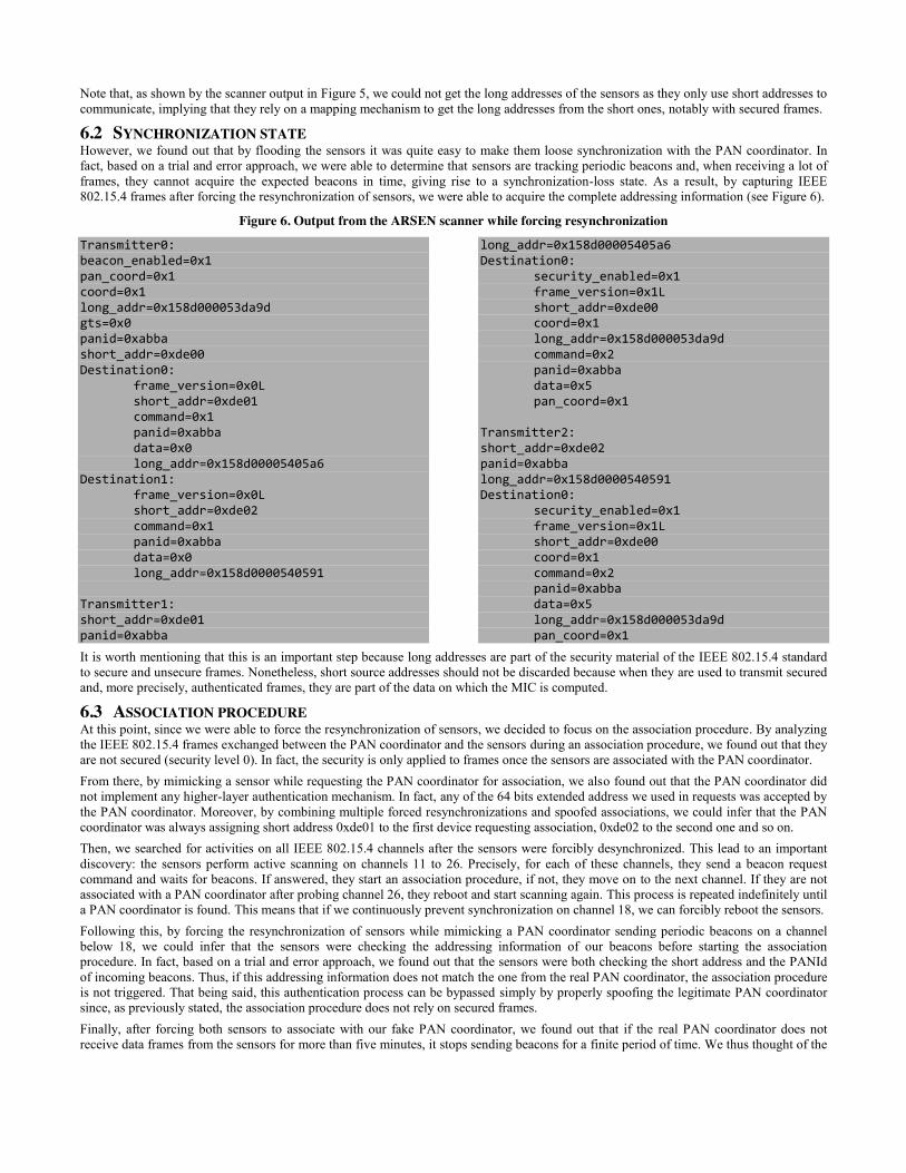
6.2 SYNCHRONIZATION STATE However, we found out that by flooding the sensors it was quite easy to make them loose synchronization with the PAN coordinator. In fact, based on a trial and error approach, we were able to determine that sensors are tracking periodic beacons and, when receiving a lot of frames, they cannot acquire the expected beacons in time, giving rise to a synchronization-loss state. As a result, by capturing IEEE 802.15.4 frames after forcing the resynchronization of sensors, we were able to acquire the complete addressing information (see Figure 6).
Figure 6. Output from the ARSEN scanner while forcing resynchronization
Transmitter0: beacon_enabled=0x1 pan_coord=0x1 coord=0x1 long_addr=0x158d000053da9d gts=0x0 panid=0xabba short_addr=0xde00 Destination0: frame_version=0x0L short_addr=0xde01 command=0x1 panid=0xabba data=0x0 long_addr=0x158d00005405a6 Destination1: frame_version=0x0L short_addr=0xde02 command=0x1 panid=0xabba data=0x0 long_addr=0x158d0000540591 Transmitter1: short_addr=0xde01 panid=0xabba
long_addr=0x158d00005405a6 Destination0: security_enabled=0x1 frame_version=0x1L short_addr=0xde00 coord=0x1 long_addr=0x158d000053da9d command=0x2 panid=0xabba data=0x5 pan_coord=0x1 Transmitter2: short_addr=0xde02 panid=0xabba long_addr=0x158d0000540591 Destination0: security_enabled=0x1 frame_version=0x1L short_addr=0xde00 coord=0x1 command=0x2 panid=0xabba data=0x5 long_addr=0x158d000053da9d pan_coord=0x1
It is worth mentioning that this is an important step because long addresses are part of the security material of the IEEE 802.15.4 standard to secure and unsecure frames. Nonetheless, short source addresses should not be discarded because when they are used to transmit secured and, more precisely, authenticated frames, they are part of the data on which the MIC is computed.
6.3 ASSOCIATION PROCEDURE At this point, since we were able to force the resynchronization of sensors, we decided to focus on the association procedure. By analyzing the IEEE 802.15.4 frames exchanged between the PAN coordinator and the sensors during an association procedure, we found out that they are not secured (security level 0). In fact, the security is only applied to frames once the sensors are associated with the PAN coordinator. From there, by mimicking a sensor while requesting the PAN coordinator for association, we also found out that the PAN coordinator did not implement any higher-layer authentication mechanism. In fact, any of the 64 bits extended address we used in requests was accepted by the PAN coordinator. Moreover, by combining multiple forced resynchronizations and spoofed associations, we could infer that the PAN coordinator was always assigning short address 0xde01 to the first device requesting association, 0xde02 to the second one and so on. Then, we searched for activities on all IEEE 802.15.4 channels after the sensors were forcibly desynchronized. This lead to an important discovery: the sensors perform active scanning on channels 11 to 26. Precisely, for each of these channels, they send a beacon request command and waits for beacons. If answered, they start an association procedure, if not, they move on to the next channel. If they are not associated with a PAN coordinator after probing channel 26, they reboot and start scanning again. This process is repeated indefinitely until a PAN coordinator is found. This means that if we continuously prevent synchronization on channel 18, we can forcibly reboot the sensors. Following this, by forcing the resynchronization of sensors while mimicking a PAN coordinator sending periodic beacons on a channel below 18, we could infer that the sensors were checking the addressing information of our beacons before starting the association procedure. In fact, based on a trial and error approach, we found out that the sensors were both checking the short address and the PANId of incoming beacons. Thus, if this addressing information does not match the one from the real PAN coordinator, the association procedure is not triggered. That being said, this authentication process can be bypassed simply by properly spoofing the legitimate PAN coordinator since, as previously stated, the association procedure does not rely on secured frames. Finally, after forcing both sensors to associate with our fake PAN coordinator, we found out that if the real PAN coordinator does not receive data frames from the sensors for more than five minutes, it stops sending beacons for a finite period of time. We thus thought of the

most probable explanation: assuming a possible failure because of the lack of incoming data, the PAN coordinator reboots to ensure service continuity. If true, this meant that we had now the capability to forcibly reboot all devices: the PAN coordinator and the sensors.
6.4 FRAMES COUNTERS Assuming that we were now able to forcibly reboot both the PAN coordinator and the sensors, we decided to focus on the frame counters.
6.4.1 INCOMING FRAME COUNTERS The incoming frame counter is part of the security material in the IEEE 802.15.4 standard and is used to ensure the sequential freshness of incoming frames. More precisely, for each known device, a given device stores an incoming frame counter that represents the last received frame counter. During the incoming frame procedure, the recipient device shall reject the received frame if the new frame counter is less than the last received frame counter. Otherwise the incoming frame counter is updated accordingly and the new incoming frame is processed. This mechanism is used to prevent replay attacks. We have been able to demonstrate that the incoming frame counters were reset to zero after the PAN coordinator has rebooted by performing the following procedure:
1. Force disassociation between the sensors and the PAN coordinator; 2. Capture the following association procedures to infer the addressing information (i.e., both short and long addresses); 3. Capture the network activity for a period long enough to catch a least one outgoing secured data frame for each sensors; 4. Spoof the PAN coordinator but with periodic beacons sent on a channel below 18; 5. Force disassociation again between the sensors and the PAN coordinator; 6. Verify that the sensors are now associated with the fake PAN coordinator; 7. Wait for the beacons from the real PAN coordinator to stop (i.e., wait for 5 minutes); 8. Spoof sensors by requesting association with the real PAN coordinator on channel 18 while meeting the addressing information
capture at step 2 (i.e., associate the fake sensors in the correct order so as to match the short addresses previously assigned); 9. For both fake sensors, replay secured packets captured at step 3; 10. Observe that this time the beacons from the real PAN coordinator do not stop after 5 minutes;
If the beacons from the real PAN coordinator in fact do not stop after 5 minutes, it means that the replayed frames were actually accepted. Consequently, it also means that the incoming frame counters have been reset to zero, confirming by the way that the PAN coordinator actually reboots in this situation. Failing to store the frame counters in non-volatile memory is a security issue we have encountered several times on actual security audits. In this particular case, a possible attack scenario would be malicious individuals replaying secured frames, thus persuading the distributed water management system of a normal activity, while contaminating the water. This is an important finding as this scenario we just considered was one on the major undesired events identified by the stakeholders behind this security audit.
6.4.2 OUTGOING FRAME COUNTERS Similarly, the outgoing frame counter is part of the security material of the IEEE 802.15.4 standard as it is used by the originator device to secure outgoing frames. More precisely, it is used to construct the nonce. As it is required by recipient device during the unsecuring procedure, it is always included in the MAC header of each secured frame. For a given originator, this counter is incremented by one each time a frame is secured. This mechanism ensures that the keying material for every frame is unique. When the frame counter reaches is maximum value of 0xffffffff the associated keying material can no longer be used, thus requiring the corresponding key to be updated. By comparing the header of secured frame emitted by a sensor before forcing a reboot (see Figure 7) and after forcing a reboot (see Figure 8), we could easily infer that the outgoing frame counters were also reset to zero upon the reboot of a sensor (in the following example, it went from 0x26000000 to 0x0). Again, failing to store the frame counters in non-volatile memory is a security issue we have encountered several times on actual security audits. This time, it opens up the possibility of conducting same-nonce attacks (see section 5.1 for details) and thus may lead to confidentiality issues. However, in this particular case, confidentiality was not considered a high priority compared to integrity and availability issues. That being said, we had already demonstrated in section 6.4.1 how to compromise both integrity and availability.
Figure 7. Dissected IEEE 802.15.4 header of a secured frame before forcing a sensor to reboot
>>> p[44].show() ###[ Gnuradio header ]### proto= 2 reserved1= 0x0 reserved2= 0 ###[ 802.15.4 ]### fcf_reserved_1= 0L fcf_panidcompress= True fcf_ackreq= True fcf_pending= False fcf_security= True fcf_frametype= Data fcf_srcaddrmode= Short fcf_framever= 1L
fcf_destaddrmode= Short fcf_reserved_2= 0L seqnum= 189 ###[ 802.15.4 Data ]### dest_panid= 0xabba dest_addr= 0xde00 src_addr= 0xde01 ###[ 802.15.4-2006 Auxiliary Security Header ]### sec_sc_reserved= 0L sec_sc_keyidmode= 1oKeyIndex sec_sc_seclevel= ENC-MIC-32 sec_framecounter= 0x26000000 sec_keyid_keyindex= 0x1

Figure 8. Dissected IEEE 802.15.4 header of a secured frame after forcing a sensor to reboot
>>> p[204].show() ###[ Gnuradio header ]### proto= 2 reserved1= 0x0 reserved2= 0 ###[ 802.15.4 ]### fcf_reserved_1= 0L fcf_panidcompress= True fcf_ackreq= True fcf_pending= False fcf_security= True fcf_frametype= Data fcf_srcaddrmode= Short fcf_framever= 1L
fcf_destaddrmode= Short fcf_reserved_2= 0L seqnum= 129 ###[ 802.15.4 Data ]### dest_panid= 0xabba dest_addr= 0xde00 src_addr= 0xde01 ###[ 802.15.4-2006 Auxiliary Security Header ]### sec_sc_reserved= 0L sec_sc_keyidmode= 1oKeyIndex sec_sc_seclevel= ENC-MIC-32 sec_framecounter= 0x0 sec_keyid_keyindex= 0x1
6.5 SECURED FRAMES Nonetheless, it is possible to compromise integrity one step further: all the conditions to implement a malleability attack are met (see section 5.3 for details). This means that, instead of replaying captured secured frames, we could go as far as forging new ones. However, this would require implementing first the same-nonce attack on a scale large enough to gather the appropriate amount of keystreams with their corresponding frame counters. Limited by time and resources, in agreement with the stakeholders, we move to a “gray-box” approach and we were therefore provided with the plaintext data of multiple captured secured frames. From there, with a reasonable amount of keystreams that could be used right after forcing the reboot of the PAN coordinator (i.e., we had to force a reboot each time we used them all), we now had all we needed to use the ARSEN router and start auditing higher-layer protocols. The continuation of this audit consisted in applying a standard penetration testing methodology, which was the purpose of the ARSEN project, but upon achievement of this goal, the rest is therefore out of the scope of this paper. It is worth mentioning that, on other security audits, we were able to conduct physical attacks to extract the firmware and access the encryption keys. This is usually the preferred and easiest way of gaining the capability to forge secured frames but, in this case, this approach was explicitly discarded by the stakeholders.
7. CONCLUSION In this paper, we have presented the ARSEN project: Advanced Routing for 6LoWPAN and Ethernet Networks. To that end, we have detailed all the mechanisms we have implemented in order to provide security auditors with the means to connect to any existing 6LoWPAN networks by supporting a wide range of IEEE 802.15.4 configurations and MAC-sublayer attacks. Then, we have demonstrated its capabilities on an actual wireless communication infrastructure dedicated to the monitoring of a water distribution network system. As for future work, it is worth noting that, initially, the ARSEN project was about developing a fully customizable IEEE 802.15.4 / 6LoWPAN network interface over Ethernet. We moved to a software-only project based on Scapy-radio because of time constraints but at the cost high latencies and expensive SDR hardware. Now that our approach has shown its usefulness on actual security audits, we plan on resuming the hardware implementation using a cheap off-the-shelf system-on-chip solution.
8. ACKNOWLEDGMENT This work was conducted by Airbus Defence and Space and was funded by ACQUEAU, the Eureka Cluster for Water, under grant from WIN4SMART (Water Information Network for Sensing, Monitoring & Actuating in Real Time) and by ITEA, the Eureka Cluster for Software-intensive Systems & Services, under grant from FUSE-IT (Future Unified System for Energy and Information Technology).
9. REFERENCES [1] IEEE Std 802.15.4-2003, IEEE Standard for Local and Metropolitan Area Networks, Part 15.4: Low-Rate Wireless Personal Area
Networks (LR-WPANs). [2] IEEE STD 802.15.4-2006, IEEE Standard for Local and Metropolitan Area Networks, Part 15.4: Low-Rate Wireless Personal Area
Networks (LR-WPANs). [3] IEEE Std 802.15.4-2011, IEEE Standard for Local and Metropolitan Area Networks, Part 15.4: Low-Rate Wireless Personal Area
Networks (LR-WPANs). [4] IEEE Std 802.15.4e-2012, IEEE Standard for Local and Metropolitan Area Networks, Part 15.4: Low-Rate Wireless Personal Area
Networks (LR-WPANs), Amendment 1: MAC Sublayer. [5] V. B. Mišić, J. Fung and J. Mišić, MAC Layer Attacks in 802.15.4 Sensor Networks, in Security in Sensor Networks, 2006, pp.27-46. [6] R. Sokullu, O. Dagdeviren et al., GTS attack: An IEEE 802.15.4 MAC Layer Attack in Wireless Sensor Networks, in the International
Journal on Advances in Internet Technology, 2009, pp.105-116. [7] J.-M. Picod, A. Lebrun, J.-C. Demay, Bringing Software Defined Radio to the Penetration Testing Community, Black Hat USA, 2014. [8] http://gnuradio.org/redmine/projects/gnuradio/wiki [9] http://secdev.org/projects/scapy