one vanderbilt structural peer review report … · tt used as a basis of this review the...
TRANSCRIPT

ONE VANDERBILT
NEW YORK, NY
STRUCTURAL PEER REVIEW REPORT
SUPER STRUCTURE
February 23, 2017
Prepared For
Hines – New York
499 Park Avenue, 12th Floor
New York, NY 10022
Prepared By
Thornton Tomasetti Inc.
51 Madison Avenue
New York, NY 10010-1603
Phone: 917.661.7800
Fax: 917.661.7801
STRUCTURAL PEER REVIEW REPORT Page 1 Februrary 23, 2016 | Project # N15369.00
ONE VANDERBILT AVENUE PEER REVIEW REPORT
TABLE OF CONTENTS
A. STRUCTURAL PEER REVIEW STATEMENT .............................................................. 3
B. EXECUTIVE SUMMARY .............................................................................................. 5
1.0 INTRODUCTION .................................................................................................................... 5
2.0 DESIGN REVIEW FINDINGS AND COMMENTS .................................................................. 5
C. DOCUMENTS RECEIVED AND STRUCTURAL DRAWING LIST ................................ 8
D. PROJECT DESCRIPTION AND SCOPE OF WORK ...................................................12
E. DRAWING REIVEW, FINDINGS AND SEVERUD RESPONSES ................................14
F. STRUCTURAL SYSTEM DESCRIPTION ....................................................................14
G. BUILDING CODE AND LOAD REVIEW .......................................................................18
1.0 BUILDING CODES ............................................................................................................... 18
2.0 MATERIAL PROPERTIES ................................................................................................... 18
3.0 STRUCTURAL LOADING .................................................................................................... 19
3.1 GRAVITY LOADS ............................................................................................................. 19
3.2 WIND LOADS ................................................................................................................... 20
3.3 SEISMIC LOADS .............................................................................................................. 22
3.4 WIND AND SEISMIC LOAD COMPARISON ................................................................... 23
3.5 LOAD COMBINATIONS ................................................................................................... 24
H. STRUCTURAL MODELING .........................................................................................25
2.0 CORE MODELING ............................................................................................................... 25
3.0 LOAD PATH REVIEW .......................................................................................................... 25
I. DYNAMIC BEHAVIOR AND SERVICEABILITY CHECK ..............................................28
4.0 DYNAMIC BEHAVIOR.......................................................................................................... 28
5.0 SERVICEABILITY CHECK ................................................................................................... 28
5.1 WIND OVERALL DEFLECTION ....................................................................................... 28
5.2 WIND INTER-STORY DRIFT ........................................................................................... 29
5.3 SEISMIC INTER-STORY DRIFT ...................................................................................... 29
J. MEMBER DESIGN CHECK .........................................................................................29
3.0 FLOOR FRAMING CHECK .................................................................................................. 29
4.0 VIBRATION CHECK ............................................................................................................. 31
5.0 COLUMN CHECK ................................................................................................................. 31
STRUCTURAL PEER REVIEW REPORT Page 2 Februrary 23, 2016 | Project # N15369.00
ONE VANDERBILT AVENUE PEER REVIEW REPORT
6.0 SHEAR WALL AND LINK BEAM CHECK ............................................................................ 31
7.0 OUTRIGGER AND TRANSFER TRUSS CHECK ................................................................ 32
6.0 STRUCTURAL INTEGRITY – KEY ELEMENT ANALYSIS ................................................. 33
7.0 FOUNDATION AND GEOTECH REPORT .......................................................................... 34

____________________
2/23/2017

STRUCTURAL PEER REVIEW REPORT Page 4 Februrary 23, 2016 | Project # N15369.00
ONE VANDERBILT AVENUE PEER REVIEW REPORT
STRUCTURAL PEER REVIEW REPORT Page 5 Februrary 23, 2016 | Project # N15369.00
ONE VANDERBILT AVENUE PEER REVIEW REPORT
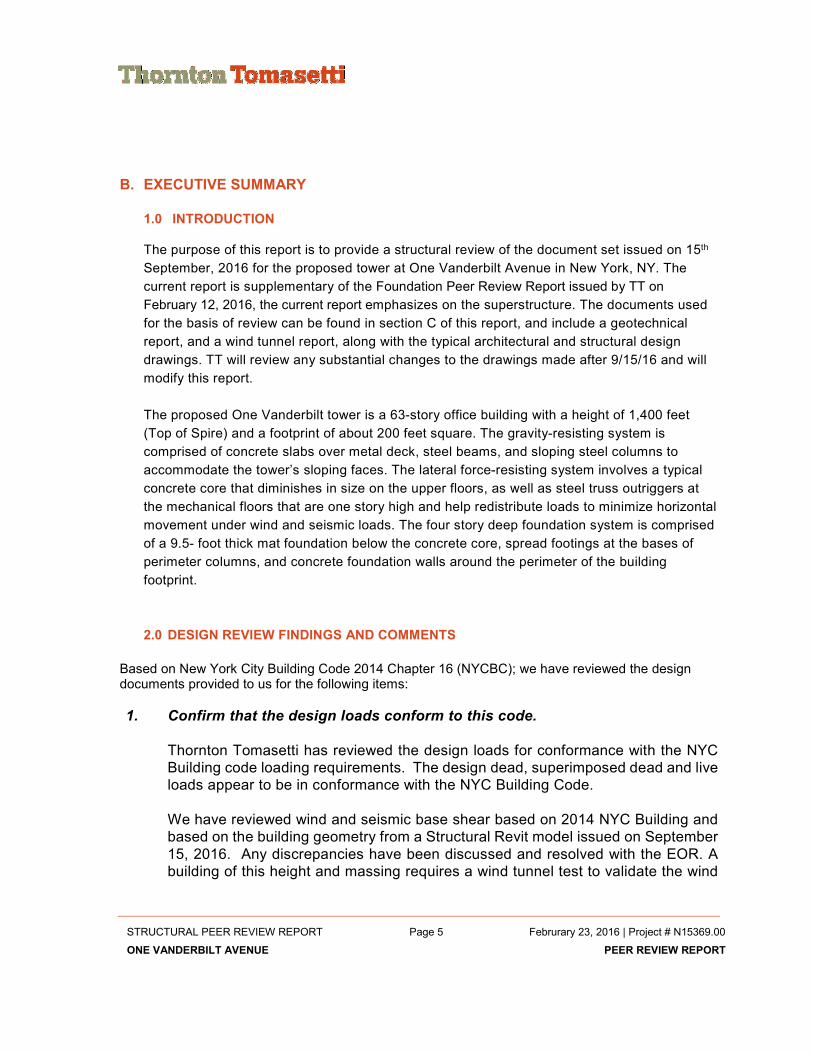
B. EXECUTIVE SUMMARY
1.0 INTRODUCTION
The purpose of this report is to provide a structural review of the document set issued on 15th
September, 2016 for the proposed tower at One Vanderbilt Avenue in New York, NY. The
current report is supplementary of the Foundation Peer Review Report issued by TT on
February 12, 2016, the current report emphasizes on the superstructure. The documents used
for the basis of review can be found in section C of this report, and include a geotechnical
report, and a wind tunnel report, along with the typical architectural and structural design
drawings. TT will review any substantial changes to the drawings made after 9/15/16 and will
modify this report.
The proposed One Vanderbilt tower is a 63-story office building with a height of 1,400 feet
(Top of Spire) and a footprint of about 200 feet square. The gravity-resisting system is
comprised of concrete slabs over metal deck, steel beams, and sloping steel columns to
accommodate the tower’s sloping faces. The lateral force-resisting system involves a typical
concrete core that diminishes in size on the upper floors, as well as steel truss outriggers at
the mechanical floors that are one story high and help redistribute loads to minimize horizontal
movement under wind and seismic loads. The four story deep foundation system is comprised
of a 9.5- foot thick mat foundation below the concrete core, spread footings at the bases of
perimeter columns, and concrete foundation walls around the perimeter of the building
footprint.
2.0 DESIGN REVIEW FINDINGS AND COMMENTS
Based on New York City Building Code 2014 Chapter 16 (NYCBC); we have reviewed the design documents provided to us for the following items:
1. Confirm that the design loads conform to this code.
Thornton Tomasetti has reviewed the design loads for conformance with the NYC
Building code loading requirements. The design dead, superimposed dead and live
loads appear to be in conformance with the NYC Building Code.
We have reviewed wind and seismic base shear based on 2014 NYC Building and
based on the building geometry from a Structural Revit model issued on September
15, 2016. Any discrepancies have been discussed and resolved with the EOR. A
building of this height and massing requires a wind tunnel test to validate the wind

STRUCTURAL PEER REVIEW REPORT Page 6 Februrary 23, 2016 | Project # N15369.00
ONE VANDERBILT AVENUE PEER REVIEW REPORT
loads on the building structure. A new wind tunnel has been performed (RWDI Wind
Test Report Dated August 5, 2016), and wind loads have been estimated from this
wind tunnel using the building stiffness properties. We have confirmed that wind
base shear and overturning moment employed by EOR are not less than ASCE-7
requirements.
2. Confirm that other structural design criteria and design assumptions conform
to this code and are in accordance with general accepted engineering practice.
The structural design criteria and design assumptions appear to be in accordance
with general engineering practice. We have resolved any discrepancies we have
found with EOR.
3. Review geotechnical and other engineering investigations that are related to
the foundation and structural design and confirm that the design properly
incorporates the results and recommendations of the investigations.
We have issued our foundation peer report on February 16, 2016. We have
checked tower base reactions based on new wind tunnel loads and compared them
with the original designed reactions. The foundation documents appear consistent
with these recommendations.
4. Confirm that the structure has a complete load path.
The superstructure documents appear to have a complete load path for the design
loads indicated. We understand framing modification may occur to framing above
the roof level; as such, TT will review major design changes and will modify this
report if required.
5. Perform Independent calculations for a representative fraction of systems,
members and details to check their adequacy. The number of representative
systems, members, and details verified shall be sufficient to form a basis for
the review’s conclusions.
We have performed independent calculations for sample of floor beams, columns,
truss elements, shear walls and link. Any discrepancies have been discussed with
the EOR and resolved accordingly.
6. Verify that performance-specified structural components (such as certain
precast concrete elements) have been appropriately specified and
coordinated with the primary building structure.

STRUCTURAL PEER REVIEW REPORT Page 7 Februrary 23, 2016 | Project # N15369.00
ONE VANDERBILT AVENUE PEER REVIEW REPORT
No performance-specified structural components are included as part of the
provided design drawings.
7. Confirm that the structural integrity provisions of the code are being followed.
We have reviewed NYCBC integrity requirements for sample of key elements and
found them in compliance with the code provisions.
8. Review the structural and architectural plans for the building. Confirm that the
structural plans are in general conformance with the architectural plans
regarding loads and other conditions that may affect the structural design.
We have reviewed typical structural plans with the architectural drawings set issued
on 9/15/16 and they are in general conformance for structural design purpose.
9. Confirm that major mechanical items are accommodated in the structural
plans.
The structural drawing loading schedule include MEP live load allowance
comparable to industry standard. The equipment weights have not shown
specifically on the design drawings.
10. Attest to the general completeness of the structural plans and specifications.
The design documents peer reviewed for this report appear generally complete.
STRUCTURAL PEER REVIEW REPORT Page 8 Februrary 23, 2016 | Project # N15369.00
ONE VANDERBILT AVENUE PEER REVIEW REPORT
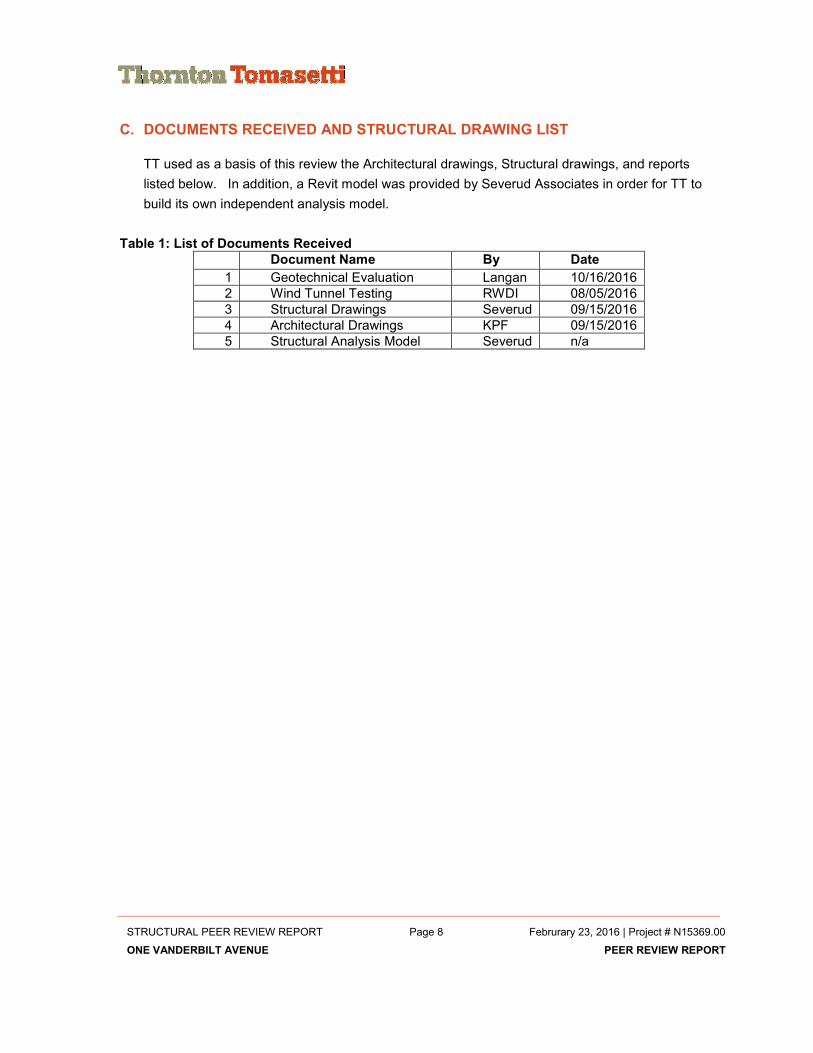
C. DOCUMENTS RECEIVED AND STRUCTURAL DRAWING LIST
TT used as a basis of this review the Architectural drawings, Structural drawings, and reports
listed below. In addition, a Revit model was provided by Severud Associates in order for TT to
build its own independent analysis model.
Table 1: List of Documents Received
Document Name By Date
1 Geotechnical Evaluation Langan 10/16/2016
2 Wind Tunnel Testing RWDI 08/05/2016
3 Structural Drawings Severud 09/15/2016
4 Architectural Drawings KPF 09/15/2016
5 Structural Analysis Model Severud n/a

STRUCTURAL PEER REVIEW REPORT Page 9 Februrary 23, 2016 | Project # N15369.00
ONE VANDERBILT AVENUE PEER REVIEW REPORT
Table 2: Drawing List Part 1

STRUCTURAL PEER REVIEW REPORT Page 10 Februrary 23, 2016 | Project # N15369.00
ONE VANDERBILT AVENUE PEER REVIEW REPORT
Table 3: Drawing List Part 2

STRUCTURAL PEER REVIEW REPORT Page 11 Februrary 23, 2016 | Project # N15369.00
ONE VANDERBILT AVENUE PEER REVIEW REPORT
Table 4: Drawing List Part 3
STRUCTURAL PEER REVIEW REPORT Page 12 Februrary 23, 2016 | Project # N15369.00
ONE VANDERBILT AVENUE PEER REVIEW REPORT
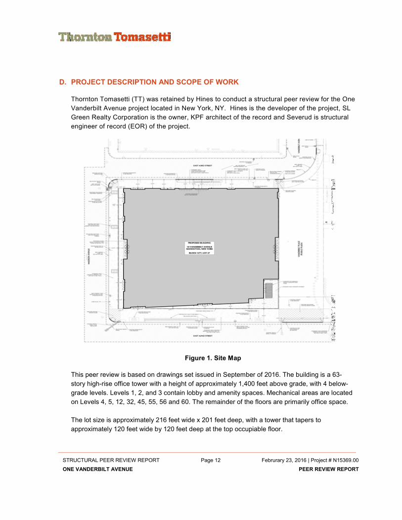
D. PROJECT DESCRIPTION AND SCOPE OF WORK
Thornton Tomasetti (TT) was retained by Hines to conduct a structural peer review for the One
Vanderbilt Avenue project located in New York, NY. Hines is the developer of the project, SL
Green Realty Corporation is the owner, KPF architect of the record and Severud is structural
engineer of record (EOR) of the project.
Figure 1. Site Map
This peer review is based on drawings set issued in September of 2016. The building is a 63-
story high-rise office tower with a height of approximately 1,400 feet above grade, with 4 below-
grade levels. Levels 1, 2, and 3 contain lobby and amenity spaces. Mechanical areas are located
on Levels 4, 5, 12, 32, 45, 55, 56 and 60. The remainder of the floors are primarily office space.
The lot size is approximately 216 feet wide x 201 feet deep, with a tower that tapers to
approximately 120 feet wide by 120 feet deep at the top occupiable floor.

STRUCTURAL PEER REVIEW REPORT Page 13 Februrary 23, 2016 | Project # N15369.00
ONE VANDERBILT AVENUE PEER REVIEW REPORT
Figure 2. Building Sections
TT’s role is to perform a peer review of the floor framing and lateral system, which includes
the overall building behavior. TT’s review is based on the Architectural and Structural
drawings dated September 15, 2016 prepared by Kohn Pederson Fox Associates (KPF) and
Severud Associates Consulting Engineers respectively. TT also studied the structural design
for compliance to the recommendations in the Geotechnical report by Langan dated October
16, 2016 and the Wind-Induced Structural Responses report by RWDI dated August 05,
2016.
TT’s scope of work as required by NYC DoB Building Code 2014 (Section 1617.5.1) is as
follows:
1. Confirm that the design loads conform to this code
2. Confirm that other structural design criteria and design assumptions conform to this code
and are in accordance with general accepted engineering practice.
3. Review geotechnical and other engineering investigations that are related to the
foundation and structural design and confirm that the design properly incorporates the
results and recommendations of the investigations.
4. Review the structural frame and the load supporting parts of floors, roofs, walls and
foundations. Cladding, cladding framing, stairs, equipment supports, ceiling supports, non-
loadbearing partitions, railings and guards, and other secondary structural items shall be

STRUCTURAL PEER REVIEW REPORT Page 14 Februrary 23, 2016 | Project # N15369.00
ONE VANDERBILT AVENUE PEER REVIEW REPORT
excluded.
5. Confirm that the structure has a complete load path
6. Perform Independent calculations for a representative fraction of systems, members, and
details to check their adequacy. The number of representative systems, members, and
details verified shall be sufficient to form a basis for the review’s conclusions.
7. Verify that performance-specified structural components (such as certain precast concrete
elements) have been appropriately specified and coordinated with the primary building
structure.
8. Verify that the design engineer of record complied with the structural integrity provisions of
the code.
9. Review the structural and architectural plans for the building. Confirm that the structural
plans are in general conformance with the architectural plans regarding loads and other
conditions that may affect the structural design.
10. Confirm that major mechanical items are accommodated in the structural plans.
11. Attest to the general completeness of the structural plans and specifications.
E. DRAWING REVIEW, FINDINGS AND SEVERUD RESPONSES
TT reviewed structural drawings, dated 16th October, 2016, to verify that structural plans are in
general conformance with the architectural plans, that major mechanical items are
accommodated in the structural plans. A general review of the structural frame and the load
supporting parts of the floors, roofs, walls and foundation was performed.
Observations and recommendations as a results of TT review and analysis of the Severud
structural drawings were sent to EOR and resolved accordingly.
F. STRUCTURAL SYSTEM DESCRIPTION
The lateral load resisting system is composed of a reinforced concrete shear wall core with steel
truss outriggers. The outriggers are one story deep at the 32nd, 45th and 55th floors, and span
between the concrete core roughly at the center of the floor plans and the perimeter steel
columns. The upper and lower chords are comprised of built-up box beam members, while the
diagonals are standard hot-rolled wide-flange shapes.

STRUCTURAL PEER REVIEW REPORT Page 15 Februrary 23, 2016 | Project # N15369.00
ONE VANDERBILT AVENUE PEER REVIEW REPORT
Figure 3. ETABS Image of Lateral System
In addition to the trusses described above acting as outriggers, there is a series of transfer
trusses on floors 5, 6, 12, and 13 that allow gravity loads to transfer where the building increases
or decreases in width. These trusses are primarily gravity system elements, but they do
contribute to the lateral system behavior as well.
The typical office floor construction is a 3” metal deck with an additional 2 1/2" of concrete, while
mechanical floors and floors directly above the mechanical floors include a 4 ½” thick normal
weight concrete topping over 3” metal deck. Steel framing supports the deck and spans between
the concrete core and perimeter steel wide-flange columns.

STRUCTURAL PEER REVIEW REPORT Page 16 Februrary 23, 2016 | Project # N15369.00
ONE VANDERBILT AVENUE PEER REVIEW REPORT
Figure 4. Typical Framing Plan

STRUCTURAL PEER REVIEW REPORT Page 17 Februrary 23, 2016 | Project # N15369.00
ONE VANDERBILT AVENUE PEER REVIEW REPORT
The foundation system consists of spread footings bearing on rock with an allowable bearing
capacity of 60tsf. A 9’-6” thick mat is set beneath the core, and individual spread footings support
most of the perimeter columns. Foundation walls typically consist of 24” double-reinforced
concrete walls.
Figure 5. Typical Foundation Section

STRUCTURAL PEER REVIEW REPORT Page 18 Februrary 23, 2016 | Project # N15369.00
ONE VANDERBILT AVENUE PEER REVIEW REPORT
G. BUILDING CODE AND LOAD REVIEW
1.0 BUILDING CODES
Based on the General Notes on S-701, and Loading Schedule on S-702, the structural design
was conducted according to the following building codes:
• 2014 Edition of the New York City Building Code
• ASCE-7 (2010), Minimum Design Loads for Buildings and other Structures
• ASCE-7 (2005), Minimum Design Loads for Buildings and other Structures
• AISC 360 (2005), Specification for Structural Steel Buildings.
• ACI-318 (2011), Building code requirements for Reinforced Concrete
• AWS D1.1 (2004), Structural Welding Code
• ASTM Standards
• AISC Design Guide 11
The building codes listed on the Peer Review Set drawings are consistent and appropriate for this
project.
2.0 MATERIAL PROPERTIES
The material properties noted in the General Notes on S-701 for the major structural elements are
noted below.
Structural Steel: ASTM A992 or ASTM A572, Grade 50
HSS Steel: ASTM A500, Grade B
Footings and Foundation Mat: 10,000 psi
Piers and Buttresses: 10,000 psi
Foundation Walls 10,000 psi
Slabs On Grade 6,000 psi
Shear Walls – Foundation to 13th Floor 14,000 psi
Shear Walls – 13th Floor - 26th Floor 12,000 psi
Shear Walls – 26th Floor - 39th Floor 10,000 psi
Shear Walls – 39th Floor - 51st Floor 8,000 psi
Shear Walls – Above 51st Floor 6,000 psi
Raised Slabs 4,000 psi
Concrete on Metal Deck 4,000 psi
Bar Reinforcing ASTM A 615, Grade 60

STRUCTURAL PEER REVIEW REPORT Page 19 Februrary 23, 2016 | Project # N15369.00
ONE VANDERBILT AVENUE PEER REVIEW REPORT
3.0 STRUCTURAL LOADING
3.1 GRAVITY LOADS
The gravity loading consists of the member self-weight, the superimposed dead load (floor finish,
partitions, ceiling & hung mechanical), and live load. The Gravity Design Loads are shown in the
Loading Schedule on S-702 of the structural drawings. The following tables summarize the types
of dead loads and live loads used, as well as TT comments.
Table 5: Dead Loads per S-702
SLAB CONSTRUCTION LOAD (PSF) COMMENTS
6" NWC SLAB 75
CONCRETE RISERS* 130
TYPE 1 55 2 1/2" NWC on 3" DECK (TYP.)
TYPE 2 80 4 1/2" NWC on 3" DECK (TYP.)
TYPE 3 115 4 1/2" NWC on 3" DECK +3” FILL (TYP.)
TYPE 4 80 4 1/2" NWC on 3" DECK (TYP.)
18" NWC SLAB 225
24" NWC SLAB 300
Table 6: Live Loads per S-702
AREA LIVE
LOAD (PSF)
TT COMMENTS
Core 100 Treat as Lobby Space
Core – Stairs 100 Per Code
Typical – Mechanical 150 75 Req'd for Equipment Rooms
Elevator Machine Room 75+*
Core- Freight Elevator Vestibule 100 Treat as a Lobby Space
Core – MEP 100 75 Req'd for Equipment Rooms
Core - Passenger Elevator Lobby 100 Treat as a Lobby Space
Core - Toilet Rooms 100 Same as Floor Load
Terrace 100 Roof for Promenade Purposes
Typical - Office 50 Office Load Explicitly Addressed in Code
Core - Elevator Machine Room 75+* Treat as an equipment rooms
Core - Back of House 100 Conservative estimation, Engineering Judgement
Temporary Construction Loading - Staging Area 250 Equivalent to "Heavy Storage Warehouses" - Reasonable

STRUCTURAL PEER REVIEW REPORT Page 20 Februrary 23, 2016 | Project # N15369.00
ONE VANDERBILT AVENUE PEER REVIEW REPORT
Temporary Construction Loading - Truck Areas 600 Typical Construction Surcharge Load
Typical – Amenity 100 Reasonably assumption
Typical - Dock Master 100 Not addressed in Code, reasonable assumption
Typical - Messenger Center 100 Not addressed in Code, reasonable assumption
Typical - Office Lobby 100 Office Lobby Load Explicitly Addressed in Code
Typical – Retail 100 Retail Load Explicitly Addressed in Code
Typical - Subway Entrance 100 Treat as a Lobby Space
Typical - Transit Hall 100
Core – Circulation 100 Treat as a Lobby Space
Typical - Toilet Rooms 50 Assumed same as floor load
Roof - Glass 40 20 psf required for Roofs, 40 psf for catwalk
Roof - Slab 100 20 psf required for Roofs
BMU-1 50 Plus BMU unit loads
BMU-2 50 Plus BMU unit loads
BMU-3 50 Plus BMU unit loads
Top Of Building 40
Typical - Trading Floor 100
B1 (Cellar) East 100
B1 (Cellar) Northwest 100
B1 (Cellar) West 100
Shuttle Platform 100
*+ Sheave Beam Reactions
TT found the Gravity loads to be acceptable and in conformance with the NYC Building Code
2014 and general practice.
3.2 WIND LOADS
The wind loads for the structural design are based on the following parameters per ASCE 7-05
and the New York City Building Code:
Design Wind Speed, V 98mph
Occupancy Category III
Wind Exposure B
Importance Factor 1.15
The existing wind tunnel report provides Effective Static Floor-by-Floor Wind loads for Fx, Fy and
Mz. In turn, these loads were used in TT’s analysis with the load factors given in 24 load
combinations. We have also compared RWDI and ASCE-7 base wind loads per following table.
Severud has confirmed that the applied wind loads in their analysis model is greater than those of
RWDI or 80% of ASCE-7 loads.

STRUCTURAL PEER REVIEW REPORT Page 21 Februrary 23, 2016 | Project # N15369.00
ONE VANDERBILT AVENUE PEER REVIEW REPORT
Table 7 Wind Load Comparison
RWDI 08/05/16 with IF TT/NYCBC 2014 ASCE 7-05
Severud/NYCBC
2014/RWDI
Wind (mph) 98 98 98
Exposure - B B
Occupancy Category - III III
Importance Factor 1.15 1.15 1.15
Height (ft) 1273.5 1288 1288
Fx (kips) EW dir.
7,372
9,611
8,510
Fy (kips) NS dir.
7,912
9,830
9,331
My (k-ft)
5,347,500
5,747,278
5,347,500
Mx (k-ft)
5,704,000
5,728,749
5,704,000
Mz (k-ft)
124,200
124,200
80% of TT ASCE 7-05 Fx 7689
80% of TT ASCE 7-05 Fy 7864
80% of TT ASCE 7-05 My 4597822
80% of TT ASCE 7-05 Mx 4582999

STRUCTURAL PEER REVIEW REPORT Page 22 Februrary 23, 2016 | Project # N15369.00
ONE VANDERBILT AVENUE PEER REVIEW REPORT
3.3 SEISMIC LOADS
The General Notes indicate that the seismic loads comply with Chapter 16 of the NYC
Building Code using the following seismic parameters:
Table 8: Seismic Parameters
Parameter Value Reference
Occupancy Category III Table 1604.5
Importance Factor, Ie 1.25 Table 11.5.1
Ss 0.281 g 1613.5.1
S1 0.073 g 1613.5.1
Site Class B Per Geotech
Fa 1.0 Table 1613.5.3(1)
Fv 1.0 Table 1613.5.3(2)
Sms 0.281 g Section 1613.5.3
Sm1 0.073 g Section 1612.5.3
Sds 0.187 g Section 1612.5.4
Sd1 0.049 g Section 1612.5.4
Design Category B Table 1616..5.6
Seismic Force Resisting System Ordinary Reinforced Concrete Shear Walls
Response Mod., R 4.0 Table 12.2-1, ASCE 7-10
Deflection Amp., Cd 4.0 Table 12.2-1, ASCE 7-10
Approx. Fundamental Period, Ta 2.00 s Eq. 12.8-7 ASCE 7-10
Fund. Period, T 3.40 s Not Listed
Seismic Weight, W Not Provided
Base Shear, V 3,911 kips Per design drawings
TT found that these parameters are consistent with the NYC Building Code and ASCE 7-
10. TT has performed an independent analysis of the seismic loads, and found the
Seismic Weight to be approximately 389,929k. Based on the building weight our
calculated seismic base shear is 4018 kips. Since the wind loads generally control the
lateral members design, the minor discrepancy between our seismic base shear and that
of EOR is acceptable.

STRUCTURAL PEER REVIEW REPORT Page 23 Februrary 23, 2016 | Project # N15369.00
ONE VANDERBILT AVENUE PEER REVIEW REPORT
3.4 WIND AND SEISMIC LOAD COMPARISON
The table and figures below show TT calculated building shear and moment for wind in the X
direction (East/West), wind in the Y direction (North/South), and for seismic design. All wind
loads include 1.15 importance factor.
Table 9: Applied lateral load comparison
Seismic vs Wind Shear Base Shear and Moment Comparison
Wind Load (RWDI*Iw) Iw=1.15 EQ Loads
Vx [k] Vy [k] My [k-ft] Mx [k-f] Vi [k] Mi [k-f]
BASE 7371 7515 5342314 5401169 4018 3167841
Figure 6: Wind vs EQ Shear
0
200
400
600
800
1000
1200
1400
0 2000 4000 6000 8000
Bu
ild
ing
He
igh
t [f
t]
Shear [kip]
WIND vs EQ SHEAR
RWDI Vx [kip] RWDI Vy [kip]
Vi-EQ [k]
0
200
400
600
800
1000
1200
1400
0 2000000 4000000 6000000
Bu
ild
ing
He
igh
t [f
t]
Moment [kip-ft]
WIND vs EQ Moments
RWDI My [k-ft] RWDI Mx [k-ft]
Mi-EQ [k-ft]

STRUCTURAL PEER REVIEW REPORT Page 24 Februrary 23, 2016 | Project # N15369.00
ONE VANDERBILT AVENUE PEER REVIEW REPORT
3.5 LOAD COMBINATIONS
The following load combinations in accordance with the NYCBC 2014 have been used to verify
members’ strength and service design. In addition, RWDI wind load cases have been included in
the following load combinations.
Ultimate (Strength) Design
1.4D
1.2D+1.6L+0.5(Lr or S or R)
1.2D+1.6(Lr or S or R)+(f1L or 0.8W)
1.2D+1.6W+f1L+0.5(Lr or S or R)
1.2D+1.0E+f1L+f2S
0.9D+1.6W
0.9D+1.0E
The load factor on L in combinations 3,4 and 5 is permitted to equal 0.5 for all occupancies in
which Live load is less than or equal to 100 psf.
Allowable Stress (Service) Design
D
D+L
D+L+(Lr or S or R)
D+0.75L+0.75(Lr or S or R)
D+(W or 0.7E)
D+0.75L+0.75(W or 0.7E)+0.75(Lr or S or R)
0.6D+W
0.6D+0.7E

STRUCTURAL PEER REVIEW REPORT Page 25 Februrary 23, 2016 | Project # N15369.00
ONE VANDERBILT AVENUE PEER REVIEW REPORT
H. STRUCTURAL MODELING
2.0 CORE MODELING
TT has built its independent model using ETABS software. The One Vanderbilt core is a
rectangular grid of concrete shear walls that is two bays wide in the East/West direction and
three bays wide in the North/South direction. While the openings for doors tend to weaken the
system, the link beams above the doors and the steel frame within the concrete will tend to
strengthen it. We have modeled walls and deep link beams with shell elements to accurately to
determine the overall building stiffness under wind and earthquake loading, and the correct load
distribution to the different walls and foundation.
Severud has not provided their analysis model for our review however, they have confirmed that
general analysis parameters such as model shapes, deflection, base reaction is in good
agreement with our analysis results.
Figure 7: Structural analysis modeling methods, shell elements for shear walls.
3.0 LOAD PATH REVIEW
The concrete core is main lateral resisting elements in tandem with outriggers truss. The core
walls are continuous from level 61 to foundation level with setbacks at level 59, 33 and 24 as
shown in Figure 8. The core walls provide a clear load path for lateral loads.
For gravity loads, typical floor steel beams transfer the loads to the perimeter sloped steel
columns and central concrete core. The steel columns are transferred at levels 12-13 and 5-6 to
provide setbacks required per building architectural design. Transfer girders and trusses at these
levels provide clear load path for the gravity loads.

STRUCTURAL PEER REVIEW REPORT Page 26 Februrary 23, 2016 | Project # N15369.00
ONE VANDERBILT AVENUE PEER REVIEW REPORT
Figure 8 Shear walls

STRUCTURAL PEER REVIEW REPORT Page 27 Februrary 23, 2016 | Project # N15369.00
ONE VANDERBILT AVENUE PEER REVIEW REPORT
Figure 9: Load Path Elevation Views
STRUCTURAL PEER REVIEW REPORT Page 28 Februrary 23, 2016 | Project # N15369.00
ONE VANDERBILT AVENUE PEER REVIEW REPORT
I. DYNAMIC BEHAVIOR AND SERVICEABILITY CHECK
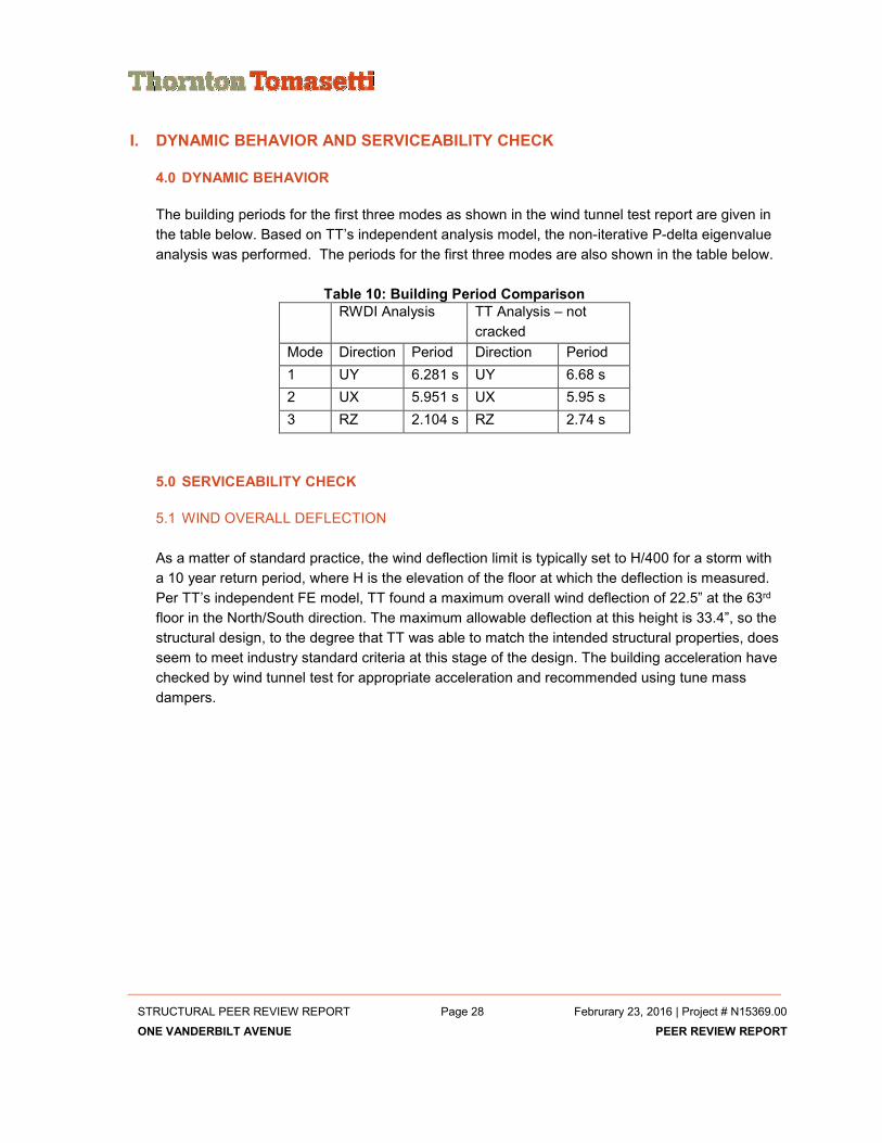
4.0 DYNAMIC BEHAVIOR
The building periods for the first three modes as shown in the wind tunnel test report are given in
the table below. Based on TT’s independent analysis model, the non-iterative P-delta eigenvalue
analysis was performed. The periods for the first three modes are also shown in the table below.
Table 10: Building Period Comparison
RWDI Analysis TT Analysis – not
cracked
Mode Direction Period Direction Period
1 UY 6.281 s UY 6.68 s
2 UX 5.951 s UX 5.95 s
3 RZ 2.104 s RZ 2.74 s
5.0 SERVICEABILITY CHECK
5.1 WIND OVERALL DEFLECTION
As a matter of standard practice, the wind deflection limit is typically set to H/400 for a storm with
a 10 year return period, where H is the elevation of the floor at which the deflection is measured.
Per TT’s independent FE model, TT found a maximum overall wind deflection of 22.5” at the 63rd
floor in the North/South direction. The maximum allowable deflection at this height is 33.4”, so the
structural design, to the degree that TT was able to match the intended structural properties, does
seem to meet industry standard criteria at this stage of the design. The building acceleration have
checked by wind tunnel test for appropriate acceleration and recommended using tune mass
dampers.

STRUCTURAL PEER REVIEW REPORT Page 29 Februrary 23, 2016 | Project # N15369.00
ONE VANDERBILT AVENUE PEER REVIEW REPORT
Figure 10: TT Wind Deflection Shape
5.2 WIND INTER-STORY DRIFT
Based on industry standard, wind inter-story drift less than h/400 is acceptable, where h is the
story height for the floor at which the relative displacements are determined. TT found a
maximum inter-story drift of 0.45” on a floor with a height of 16.5 ft. On such a floor the allowable
story drift is 0.5”, so the criteria are met. However, the curtain wall system and other equipment
shall be designed for such a drift limit.
5.3 SEISMIC INTER-STORY DRIFT
TT reviewed the inter-story drift due to seismic (δ = (Cd/Ie)*δe) for a limit of 0.02h as per the
Building Code. TT calculated the seismic inter-story drift and it was found that the maximum
value was 1.4” at a story of height 16.5 ft. The allowable drift is 3.96” by the criteria above, so the
criteria is met. However, the curtain wall system and other equipment shall be designed for such
a drift limit.
J. MEMBER DESIGN CHECK
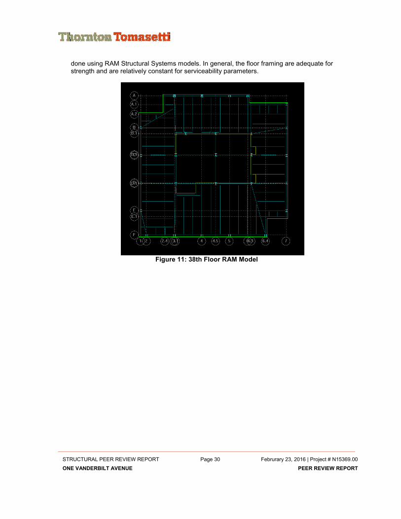
3.0 FLOOR FRAMING CHECK
TT has checked floor framing for typical composite floors 15 and 38 and has that concluded that floor framing has been design to NYC Building Code and AISC 360. Floor framing checks where
STRUCTURAL PEER REVIEW REPORT Page 30 Februrary 23, 2016 | Project # N15369.00
ONE VANDERBILT AVENUE PEER REVIEW REPORT
done using RAM Structural Systems models. In general, the floor framing are adequate for strength and are relatively constant for serviceability parameters.
Figure 11: 38th Floor RAM Model

STRUCTURAL PEER REVIEW REPORT Page 31 Februrary 23, 2016 | Project # N15369.00
ONE VANDERBILT AVENUE PEER REVIEW REPORT
4.0 VIBRATION CHECK
TT’s check of the typical floor framing (Level 38) concluded that the floor framing vibration
accelerations are within the acceptable levels described in AISC Design Guide 11 (2016).
Figure 12: Vibration Analysis
5.0 COLUMN CHECK
TT performed column checks on a sample of columns and verified that they have sufficient
capacity for loads and load combinations as required by NYC Building Code 2014. TT calculated
column reactions at the foundation match those calculated by Severud, see foundation peer
review report issued by TT on February 12th, 2016.
6.0 SHEAR WALL AND LINK BEAM CHECK
We have checked a limited number of shear walls based on our independent analysis model and
confirmed their design. We have resolved our discrepancies on link beam design with EOR and
modification will be applied to the drawings.

STRUCTURAL PEER REVIEW REPORT Page 32 Februrary 23, 2016 | Project # N15369.00
ONE VANDERBILT AVENUE PEER REVIEW REPORT
7.0 OUTRIGGER AND TRANSFER TRUSS CHECK
TT checked a sample of Outrigger and Transfer trusses have sufficient capacities for loading as
per NYC Building code load combinations. Additionally truss forces shown on SA S-500 series
drawings match or exceed forces calculated by TT.
Figure 13: 45th Floor Outrigger Wind Loads
A sample of transfer trusses at the 12th and 6th floors have been checked by TT . Transfer
trusses have been checked for Seismic with Overstrength factor (Ω=3), in addition to gravity
and wind loads, as required by NYC building Codes and ASCE 7 for vertical structural
irregularities.
Figure 14: Truss 12TR06 Member sample Checks

STRUCTURAL PEER REVIEW REPORT Page 33 Februrary 23, 2016 | Project # N15369.00
ONE VANDERBILT AVENUE PEER REVIEW REPORT
6.0 STRUCTURAL INTEGRITY – KEY ELEMENT ANALYSIS
Section BC1616 of the NYC Building Code requires integrity checks to be performed on “ key elements of the building, which falls under the code requirements due to the building aspect ratio higher than 7 and also its height greater than 600ft. Key elements of the structural system, including its connections, are elements which when lost result in more that local collapse or whose tributary area exceeds 3000 square feet on a single level. Additionally elements that brace a key element, which result in failure of the key element are also considered as key elements. Our review for representative key elements indicates that they meet the integrity requirements for Key Elements via the “specific load resistance method”, where key elements shall be designed using specific local loads, as 1616.7 NYC Building Code.
1. “Each compression element shall be designed for a concentrated load equal to 2 percent of its axial load but not less than 15 kips, applied at midspan in any direction, perpendicular to its longitudinal axis. This load shall be applied in combination with the full dead load and 50 percent of the live load in the compression element.” TT verified a sample, two (2) columns, (2) outrigger diagonals, (2) shear walls of axial member for the integrity requirements. The sample used for the study are Column 22 at Lvl13; Column 5 at Lvl 33, diagonals from trusses 5TR06 and 45TR02, and shear wall A at the 7th floor and shear wall D at the 1st floor.
2. “Each bending element shall be designed for the combination of the principal acting moments plus an additional moment, equal to 10 percent of the principal acting moment applied in the perpendicular plane.” Walls A and G at the 7th and 1st floor respectably where checked and confirmed to be designed for 10% of the principal acting moment applied in the perpendicular plane.
3. “Connections of each tension element shall be designed to develop the smaller of the ultimate tension capacity of the member or three times the force in the member.”
It is understood through communication with the connection engineer that the
connection provision 3 above is being followed for key element connection
design. An example of such location are hanger connections for columns 12 and
13 below the 13th floor. These hangers where connection for their full tension
capacity,
4. “All structural elements shall be designed for a reversal of load. The reversed load shall be equal to 10 percent of the design load used in sizing the member.” Our sample check of beams, columns and walls are adequate for this requirement.

STRUCTURAL PEER REVIEW REPORT Page 34 Februrary 23, 2016 | Project # N15369.00
ONE VANDERBILT AVENUE PEER REVIEW REPORT
Figure 15: 5TR06 Diagonal integrity sample check
Figure 16: 45TR02 Diagonal integrity sample check
7.0 FOUNDATION AND GEOTECH REPORT
For foundation review topics and Geotechnical report, refer to the foundation peer review report
issued by TT on February 12, 2016. We have checked the reactions of core wall at foundation
level based on new wind tunnel loads, model (shorter building), and found out they are generally
less than loads that sued to design the foundation as reported in our previous report.