on the theory and numerical simulation of cohesive crack ...siva shankar rudraraju, krishna...
TRANSCRIPT
Siva Shankar Rudraraju, Krishna Garikipati, and Anthony M. WaasUniversity of Michigan, Ann Arbor, Michigan
Brett A. BednarcykGlenn Research Center, Cleveland, Ohio
On the Theory and Numerical Simulation ofCohesive Crack Propagation With Applicationto Fiber-Reinforced Composites
NASA/TP—2013-217431
August 2013
https://ntrs.nasa.gov/search.jsp?R=20140000319 2020-05-28T00:55:22+00:00Z

NASA STI Program . . . in Profi le
Since its founding, NASA has been dedicated to the advancement of aeronautics and space science. The NASA Scientifi c and Technical Information (STI) program plays a key part in helping NASA maintain this important role.
The NASA STI Program operates under the auspices of the Agency Chief Information Offi cer. It collects, organizes, provides for archiving, and disseminates NASA’s STI. The NASA STI program provides access to the NASA Aeronautics and Space Database and its public interface, the NASA Technical Reports Server, thus providing one of the largest collections of aeronautical and space science STI in the world. Results are published in both non-NASA channels and by NASA in the NASA STI Report Series, which includes the following report types: • TECHNICAL PUBLICATION. Reports of
completed research or a major signifi cant phase of research that present the results of NASA programs and include extensive data or theoretical analysis. Includes compilations of signifi cant scientifi c and technical data and information deemed to be of continuing reference value. NASA counterpart of peer-reviewed formal professional papers but has less stringent limitations on manuscript length and extent of graphic presentations.
• TECHNICAL MEMORANDUM. Scientifi c
and technical fi ndings that are preliminary or of specialized interest, e.g., quick release reports, working papers, and bibliographies that contain minimal annotation. Does not contain extensive analysis.
• CONTRACTOR REPORT. Scientifi c and
technical fi ndings by NASA-sponsored contractors and grantees.
• CONFERENCE PUBLICATION. Collected papers from scientifi c and technical conferences, symposia, seminars, or other meetings sponsored or cosponsored by NASA.
• SPECIAL PUBLICATION. Scientifi c,
technical, or historical information from NASA programs, projects, and missions, often concerned with subjects having substantial public interest.
• TECHNICAL TRANSLATION. English-
language translations of foreign scientifi c and technical material pertinent to NASA’s mission.
Specialized services also include creating custom thesauri, building customized databases, organizing and publishing research results.
For more information about the NASA STI program, see the following:
• Access the NASA STI program home page at http://www.sti.nasa.gov
• E-mail your question to [email protected] • Fax your question to the NASA STI
Information Desk at 443–757–5803 • Phone the NASA STI Information Desk at 443–757–5802 • Write to:
STI Information Desk NASA Center for AeroSpace Information 7115 Standard Drive Hanover, MD 21076–1320
Siva Shankar Rudraraju, Krishna Garikipati, and Anthony M. WaasUniversity of Michigan, Ann Arbor, Michigan
Brett A. BednarcykGlenn Research Center, Cleveland, Ohio
On the Theory and Numerical Simulation ofCohesive Crack Propagation With Applicationto Fiber-Reinforced Composites
NASA/TP—2013-217431
August 2013
National Aeronautics andSpace Administration
Glenn Research CenterCleveland, Ohio 44135
Acknowledgments
The authors wish to acknowledge the support of the University of Michigan Ann Arbor, NASA Glenn Research Center, and Collier Research Corporation. This work has benefi ted from the fi nancial support of Collier Research Corporation through a NASA NRA award. Especially, the interest and encouragement of Steven M. Arnold of NASA Glenn Research Center is gratefully acknowledged. Finally, we thank Laura R. Becker and the publication services at NASA Glenn Research Center for their valuable and patient help with the editing and formatting of this report.
Available from
NASA Center for Aerospace Information7115 Standard DriveHanover, MD 21076–1320
National Technical Information Service5301 Shawnee Road
Alexandria, VA 22312
Available electronically at http://www.sti.nasa.gov
Trade names and trademarks are used in this report for identifi cation only. Their usage does not constitute an offi cial endorsement, either expressed or implied, by the National Aeronautics and
Space Administration.
Level of Review: This material has been technically reviewed by expert reviewer(s).
NASA/TP—2013-217431 iii
Contents
1.0 Introduction .......................................................................................................................................................... 1 1.1 Motivation ................................................................................................................................................... 1 1.2 Analytical Challenges .................................................................................................................................. 2 1.3 Numerical Challenges .................................................................................................................................. 2 1.4 Adopted Approach and Goals ...................................................................................................................... 2 1.5 Outline ......................................................................................................................................................... 3
2.0 Mechanics of Cohesive Crack Propagation .......................................................................................................... 3 2.1 Crack Propagation in Cohesive Materials .................................................................................................... 3
2.1.1 Classical Fracture Mechanics .......................................................................................................... 3 2.1.2 Small Process Zone and Barenblatt Cohesive Model ...................................................................... 6
2.2 Crack Propagation in Bridging Materials .................................................................................................... 7 2.2.1 Large Process Zone and Traction-Separation Models ..................................................................... 7 2.2.2 Cohesive Zone Model and Other Numerical Methods .................................................................... 8
2.3 Crack Propagation in Fiber-Reinforced Composites ................................................................................... 9 2.3.1 Micromechanics ............................................................................................................................ 10
2.4 Closing Remarks ........................................................................................................................................ 10 3.0 Multiscale Framework and Variational Formulation .......................................................................................... 11
3.1 Background and Variational Multiscale Concept ...................................................................................... 11 3.1.1 Grid-Scale Model: Large-Scale and Small-Scale .......................................................................... 11 3.1.2 Subgrid-Scale Model: Coarse-Scale and Fine-Scale ..................................................................... 12
3.2 Cracks as Subgrid Scales: Motivation and Challenges .............................................................................. 13 3.3 Multiscale Formulation of Discontinuous Displacement ........................................................................... 14 3.4 Fine-Scale Field and Micromechanics Embedding .................................................................................... 15 3.5 Closing Remarks ........................................................................................................................................ 16
4.0 Finite Element Implementation .......................................................................................................................... 16 4.1 Mesh Sensitivity of Standard Galerkin Basis ............................................................................................ 16
4.1.1 Pathological Mesh Dependence of Strain Localization in Softening Materials ............................ 16 4.1.2 Discretization Sensitivity of Crack Paths ...................................................................................... 17
4.2 Multiscale Element Construction ............................................................................................................... 18 4.2.1 Shape Functions ............................................................................................................................ 18 4.2.2 Numerical Quadrature ................................................................................................................... 20
4.3 Finite-Dimensional Weak Forms and Discretized Equations .................................................................... 21 4.4 Incremental Solution Procedure ................................................................................................................. 22 4.5 Closing Remarks ........................................................................................................................................ 23
5.0 Numerical Simulations ....................................................................................................................................... 23 5.1 Mesh Objectivity Demonstration ............................................................................................................... 24
5.1.1 Straight Crack Propagation ........................................................................................................... 24 5.1.2 Curved Crack Propagation ............................................................................................................ 24
5.2 Mixed-Mode Crack Propagation................................................................................................................ 24 5.3 Interacting and Multiple Cracks................................................................................................................. 29 5.4 Closing Remarks ........................................................................................................................................ 31
6.0 Experimental Validation and Analysis ............................................................................................................... 32 6.1 Experimental Setup .................................................................................................................................... 32
6.1.1 Characterization of Cohesive Properties ....................................................................................... 32 6.1.2 Crack Propagation Case Studies ................................................................................................... 33
6.2 Numerical Simulations and Comparison With Experiments ..................................................................... 34 6.3 Closing Remarks ........................................................................................................................................ 37
7.0 Conclusions and Future Work ............................................................................................................................ 37 Appendix—Analytical and Numerical Modeling of the Micromechanics of Fiber Pullout ........................................ 39
A.1 Introduction ............................................................................................................................................... 39 A.2 Analytical Formulation .............................................................................................................................. 39
A.2.1 Interface Crack Initiation and Frictional Contact .......................................................................... 39 A.2.2 Interface Crack Propagation .......................................................................................................... 40 A.2.3 Fiber Pullout .................................................................................................................................. 41
NASA/TP—2013-217431 iv
A.2.4 Summary ....................................................................................................................................... 42 A.3 Numerical Framework and Simulations .................................................................................................... 42
References ................................................................................................................................................................... 45
NASA/TP—2013-217431 1
On the Theory and Numerical Simulation of Cohesive Crack Propagation With Application to Fiber-Reinforced Composites
Siva Shankar Rudraraju, Krishna Garikipati, and Anthony M. Waas
University of Michigan Ann Arbor, Michigan 48109
Brett A. Bednarcyk
National Aeronautics and Space Administration Glenn Research Center Cleveland, Ohio 44135
Summary The phenomenon of crack propagation is among the
predominant modes of failure in many natural and engineering structures, often leading to severe loss of structural integrity and catastrophic failure. Thus, the ability to understand and a priori simulate the evolution of this failure mode has been one of the cornerstones of applied mechanics and structural engineering and is broadly referred to as “fracture mechanics.” The work reported herein focuses on extending this understanding, in the context of through-thickness crack propagation in cohesive materials, through the development of a continuum-level multiscale numerical framework, which represents cracks as displacement discontinuities across a surface of zero measure. This report presents the relevant theory, mathematical framework, numerical modeling, and experimental investigations of through-thickness crack propagation in fiber-reinforced composites using the Variational Multiscale Cohesive Method (VMCM) developed by the authors.
1.0 Introduction
This section provides an introduction to the phenomenon of cohesive crack propagation and its numerical simulation. Beginning with a motivation for studying crack propagation in materials with complex microstructures in Section 1.1, the relevant analytical and numerical challenges are discussed in Sections 1.2 and 1.3, respectively. Then the approach adopted and the specific goals are laid out in Section 1.4, and an outline of the remainder of the report is provided in Section 1.5.
1.1 Motivation
On application of external forces, the primary mode of response of a solid is the stretching of interatomic bonds, which is globally manifested as material deformation. Understanding the resulting continuum scale kinematics and constitutive behavior of this deformation response, within the limit of recoverability (elastic limit), are addressed in detail by the theory of elasticity (Refs. 1 to 5). Exceeding the elastic limit leads to irreversible microstructural changes like movement of
atomic dislocations and growth of mircocracks and microvoids, or it results in macroscopic configurational changes involving internal surface creation. The phenomenological descriptions of the microstructural changes, as required by the principles of irreversible thermodynamics, introduce new internal variables whose evolution is the subject matter of the theory of plasticity (Refs. 6 to 9) for metallic solids, and damage mechanics (Refs. 10 and 11) for materials with microcracking.
The creation of internal surfaces, referred to as “cracks,” do not necessarily involve changes in the continuum constitutive response of the intact solid, but rather is a problem of unknown or moving boundaries, driven by the external loading and regular constitutive response of the material. Such problems of evolving boundaries are not uncommon in continuum physics, and some other examples are Stefan’s problem of freezing in heat conduction, phase boundaries in multiphase mixtures, and fluid flow past bodies in the presence of shock waves. The challenges here are the prediction of the surface formation and tracking its subsequent evolution. In the context of cracks, this results in global nonlinearity of the load response, which in general is not analytically tractable. Further, depending on the microstructure of the material, crack formation may also manifest in addition to the continuum elastic response, new constitutive relations, which can span across different length scales. These additional cohesive relations between the crack face opening and its internal tractions, referred to as “traction-separation relations,” lead to the more challenging class of cohesive cracks and bridging cracks, where the crack surface may be a diffuse zone of damage rather than a sharp boundary.
Consider the case of through-thickness crack propagation in fiber-reinforced composites. Because of the different length scales associated with the microstructure of a composite material and the resulting composite structure, a multitude of failure mechanisms can be simultaneously operative, leading to a very complex damage progression in a composite structure. A sharp, through-thickness crack can be present in these composites initially, but as soon as local damage (possibly in the form of matrix microcracking) accumulates, crack blunting and distributed damage occurs across the highly stressed areas around the initial crack tip. As this initial crack starts to grow, a damaged zone of material (bridging zone) evolves in the wake of the instantaneous crack tip. Thus, unlike in monolithic
NASA/TP—2013-217431 2
materials such as metals, there is actually no well-defined crack that can be identified. Instead, a diffused zone of damage is seen to advance. This distributed damage results in additional resistance to advancing damage growth, largely due to fiber bridging and pullout in the crack wake. This enhanced fracture resistance is desirable and is a major contributor to the increased toughness of laminated composites (Refs. 12 to 15).
Overall, problem of determining the evolution of crack boundaries and their interaction with the continuum deformation fields represents a highly nonlinear system, with significant analytical and numerical challenges, which are briefly discussed below.
1.2 Analytical Challenges
The study of crack formation and propagation, referred to as “fracture mechanics,” was founded in the seminal work on brittle cracks by Griffith (Ref. 16), which introduced the energy-based approach to crack propagation. This was followed by major advances in the form of a stress-intensity-based approach of Irwin (Ref. 17) and softening and plastic process zone models introduced by Barenblatt (Ref. 18) and Dugdale (Ref. 19); which were further extended by Cherepanov (Ref. 20) and Rice (Ref. 21). These models are discussed in detail in Section 2.1.1. However, these theories are restricted to brittle or ductile materials with structurally insignificant or small zones of nonlinearity ahead of the crack tip (process zones), and thus they cannot be applied directly to derive conditions on crack initiation or propagation in materials characterized by large process zones. This latter class of materials is the focus of the research presented here.
Several physical mechanisms may contribute to this type of damage. Microcracking, fiber bridging, coalescence of voids, and other microstructural mechanisms can give rise to a process zone that is considerably larger than that permitted for the application of linear elastic fracture mechanics (LEFM) models. Furthermore, the material nonlinearity that is induced by these mechanisms leads to a relief of the singular fields at the mathematically sharp crack tip, which would otherwise persist in a strict LEFM setting of an elastic material. A new
length scale, 2max/E , emerges that is related to a characteristic
elastic modulus E, fracture toughness , and cohesive strength, max. If this length scale is larger than any characteristic length scale in the problem, then cohesive zone models (CZMs), which embed process zone mechanics through nonlinear traction-separation relationships across the crack faces, become important tools for analysis (Refs. 22 to 27). However determining these traction-separation relations is very challenging and often subject to the material microstructure, as will be illustrated in Section 2.2.1 and the appendix.
1.3 Numerical Challenges
Numerical schemes, like the finite element method, have become the mainstay for solution of problems involving any of
the broad phenomena of material deformation—elasticity, plasticity, and damage—so it may be tempting to use traditional finite-element-based discretization for problems of crack propagation. However, the distinguishing characteristic of crack problems in general is the formation and propagation of sharp boundaries, which are not part of the original boundary value problem. This is not an obstacle if the resulting crack path is known a priori and the mesh is ensured to have elemental surfaces align along possible crack surfaces; in practice however, neither condition is feasible. For most crack propagation problems, the crack path is not known beforehand and has to be determined as part of the solution process; in structural-level problems, adaptive mesh generation and realignment is costly. Furthermore, a standard Galerkin implementation will lead to the introduction of spurious numerical length scales proportional to the element volume as discussed in Section 4.1.
These problems with traditional finite element method implementations have been well documented for the phenomena of strain localization, which has similar kinematics to that of crack propagation problems. Thus, they exhibit spurious mesh-related length scales (Refs. 28 to 31) and problems related to mesh alignment relative to the localization band (Refs. 32 and 33).
As will be shown in Sections 4.0 and 5.0, the multiscale formulation presented in this report, involving elemental enrichment to capture the discontinuous modes associated with crack propagation, eliminates these mesh-related problems. It is also noted that a comparable but significantly different development—involving nodal enrichment by partition of unity functions—like the extended finite element method (XFEM) (Refs. 34 to 37) also results in mesh-objective simulation of crack problems. The differences between the two approaches will be highlighted in Section 4.0.
1.4 Adopted Approach and Goals
The primary task of this report is developing a numerical framework for cohesive crack propagation and demonstrating its effectiveness by simulating failure through crack propagation in materials with complex microstructure, like fiber-reinforced composites. To accomplish this goal the following approach has been adopted:
(1) Reviewing existing theories of brittle and cohesive crack propagation to determine their capabilities and limitations.
(2) Developing a general approach to cohesive crack propagation involving large process zones and also obtaining (analytically or numerically) the relevant cohesive constitutive behavior of a class of fiber-reinforced composites.
(3) Extending the idea of variational multiscale method presented in Hughes (Ref. 38) and Garikipati and Hughes (Ref. 39) and developing it on the lines of Garikipati (Ref. 40) for application to cohesive crack propagation involving discontinuous kinematics.
(4) Developing a class of finite elements that objectively simulate crack propagation without introducing any spurious
NASA/TP—2013-217431 3
numerical length scales. This involves application of nontraditional discontinuous shape functions and relevant quadrature schemes.
(5) Implementing a robust crack tracking algorithm that allows the propagation of the discontinuity surface across elements subject to physically consistent crack propagation directions.
(6) Sufficiently benchmarking the developed numerical framework by simulating complex crack propagation problems involving curved cracks, multiple cracks, interacting cracks, and so forth.
(7) Experimentally validating the theoretical and numerical approaches by comparing the load-displacement response and crack paths observed in large-scale bridged crack propagation in laminated fiber-reinforced composite specimens.
It is expected that achieving these goals would be sufficient to demonstrate and validate a physically consistent and numerically objective cohesive crack propagation framework.
1.5 Outline
An outline of the rest of the publication is as follows. Section 2.0 reviews the classical theories of crack propagation and later developments relevant to cohesive cracks involving large process zones. It then presents a possible description of the micromechanics behind bridging cracks formation in fiber-reinforced composites. In Section 3.0 the variational multiscale concept of problems involving grid- and subgrid-scale phenomena is introduced. Then the concept is extended to cracks represented as discontinuous displacement modes and the relevant weak formulation of the problem is derived. This formulation is then cast in a finite element framework in Section 4.0, which begins with a discussion of the limitations of standard finite element approaches to simulate crack propagation. It then proceeds to the multiscale element construction and development of the discretized equations and an incremental solution procedure. The analytical and numerical framework developed until this point is validated through simulation of various crack propagation problems in Section 5.0 and then by comparison with experimental observations in Section 6.0. The conclusions and possible areas of future work are summarized in Section 7.0, and lastly a framework for deriving traction-separation relations is discussed in the appendix.
2.0 Mechanics of Cohesive Crack Propagation
The study of crack propagation, commonly referred to as “fracture mechanics,” has historically focused on predicting crack evolution in homogeneous materials with brittle or quasi-brittle behavior. However, with the advent of advanced materials like composites, which possess high stiffness,
superior damage tolerance, and improved thermomechanical propagation are not adequate. The work presented here develops an analytical and numerical framework to address crack propagation in one such important class of advanced materials, fiber composites, which often exhibit large process zone sizes. To do that, this section begins with a brief discussion of classical fracture mechanics in Section 2.1.1. Then an enrichment of classical ideas using the cohesive zone approach proposed by Barenblatt (Ref. 18) is discussed in Section 2.1.2. The presentation is significantly influenced by Raizer (Ref. 41). With the theoretical framework laid out, the phenomena of toughening in materials involving large process zones is discussed in Section 2.2, and this is extended to fiber composites in Section 2.3. Finally, the closing remarks are provided in Section 2.4.
2.1 Crack Propagation in Cohesive Materials
A brief description of the two broad theories of classical fracture mechanics (energy-based method and stress-based method) and Barenblatt’s extension to cohesive fracture with a small process zone are presented in this subsection.
2.1.1 Classical Fracture Mechanics
From the continuum viewpoint, fracture (crack formation) is the creation of new surfaces in the domain of the body. This surface creation invariably leads to loss in the global stiffness and load-bearing ability of the material, often leading to failure. Traditionally, either energy-based or stress-intensity-based approaches have been employed to predict this mode of failure. The energy-based theory of failure introduced by Griffith (Ref. 16) was motivated by the inadequacy of the elastic solution that renders singular stresses at the mathematically sharp crack tip. Subsequently, Griffith’s work formed the basis for LEFM. In this section, a concise discussion of the key elements of LEFM and a subsequent development referred to as the “stress-intensity-based approach” will be presented.
2.1.1.1 Griffith’s Energy-Based Theory of Crack Propagation
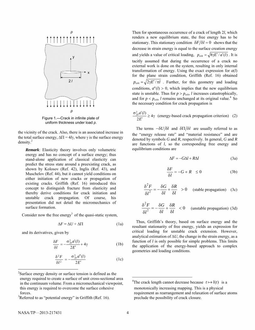
Consider an infinite plate of uniform thickness under homogeneous tensile stress state, yy, produced because of the far-field application of uniform distributed load p (= yy) as shown in Figure 1. Considering linear elasticity, the strain energy density of the body is given by EU yy 2/2 , where E is the modulus.1 If a crack of length l with traction-free faces appears in this infinite domain, then the change in strain energy is given by ElaU yy 2/)(2 , where a(l) is a positive-valued
function representing the effective area of stress relaxation in 1Plain-stress condition: E = E and plain-strain condition:
21 EE , where E is the Young's Modulus and , the
Poisson's ratio.
NASA/TP—2013-217431 4
the vicinity of the crack. Also, there is an associated increase in the total surface energy, = 4l, where is the surface energy density.2
Remark: Elasticity theory involves only volumetric energy and has no concept of a surface energy; thus stand-alone application of classical elasticity can predict the stress state around a preexisting crack, as shown by Kolosov (Ref. 42), Inglis (Ref. 43), and Muschelov (Ref. 44), but it cannot yield conditions on either initiation of new cracks or propagation of existing cracks. Griffith (Ref. 16) introduced this concept to distinguish fracture from elasticity and thereby derive conditions for crack initiation and unstable crack propagation. Of course, his presentation did not detail the micromechanics of surface formation.
Consider now the free energy3 of the quasi-static system,
F = U + (1a)
and its derivatives, given by
42
)(2
Ela
lF yy (1b)
E
lalF yy
2
)(2
2
2
(1c)
2Surface energy density or surface tension is defined as the energy required to create a surface of unit cross-sectional area in the continuum volume. From a micromechanical viewpoint, this energy is required to overcome the surface cohesive forces.
3Referred to as “potential energy” in Griffith (Ref. 16).
Then for spontaneous occurrence of a crack of length 2l, which renders a new equilibrium state, the free energy has to be stationary. This stationary condition 0 lF shows that the
decrease in strain energy is equal to the surface creation energy
and yields a value of critical loading, )(/8crit laEp . It is
tacitly assumed that during the occurrence of a crack no external work is done on the system, resulting in only internal transformation of energy. Using the exact expression for a(l) for the plane strain condition, Griffith (Ref. 16) obtained
lEp /2crit . Further, for this geometry and loading
conditions, a(l) 0, which implies that the new equilibrium state is unstable. Thus for p pcrit, l increases catastrophically, and for p pcrit, l remains unchanged at its original value.4 So the necessary condition for crack propagation is
42
)(2
Elayy (energy-based crack propagation criterion) (2)
The terms lU and l are usually referred to as
the “energy release rate” and “material resistance” and are denoted by symbols G and R, respectively. In general, G and R are functions of l, so the corresponding free energy and equilibrium conditions are
lRlGF (3a)
0
RG
lF
(3b)
02
2
lR
lG
lF
(stable propagation) (3c)
02
2
lR
lG
lF
(unstable propagation) (3d)
Thus, Griffith’s theory, based on surface energy and the resultant stationarity of free energy, yields an expression for critical loading for unstable crack extension. However, analytical estimation of U, the change in the strain energy, as a function of l is only possible for simple problems. This limits the application of the energy-based approach to complex geometries and loading conditions.
4The crack length cannot decrease because )(tlt is a
monotonically increasing mapping. This is a physical requirement as rearrangement and relaxation of surface atoms preclude the possibility of crack closure.
NASA/TP—2013-217431 5
2.1.1.2 Irwin’s Stress-Intensity-Based Theory of Crack Propagation
The key idea behind the stress-intensity-based theory is the observation that the near-tip crack field in linear elastic materials is similar for all specimen geometry and loading conditions, to within a constant. For the crack loading shown in Figure 1, Williams (Ref. 45) and Irwin (Ref. 17) obtained the crack-tip opening stress and corresponding displacement along the x axis:
)1(Ox
Kyy (4a)
)(||4 2/3xOxEKuyy
(4b)
where O denotes the higher-order terms in the asymptotic
expansion of the singular stress field. The constant K , the coefficient of stress intensity, determines the stress and strain field in the vicinity of the crack tip and is dependent on the specimen geometry, crack dimensions, and loading conditions. Having derived the stress and strain fields, Irwin used the following crack closure analysis to determine the value of the energy release rate G.
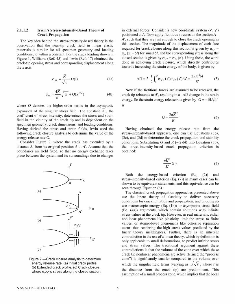
Consider Figure 2, where the crack has extended by a distance l from its original position A to A. Assume that the boundaries are held fixed, so that no energy exchange takes place between the system and its surroundings due to changes
in external forces. Consider a new coordinate system (x, y) positioned at A. Now apply fictitious stresses on the section A – A, such that they are just enough to close the crack opening in this section. The magnitude of the displacement of each face required for crack closure along this section is given by uyy = uyy (x – l) for small l, and the corresponding stress along the closed section is given by yy = yy (x). Using these, the work done in achieving crack closure, which directly contributes towards increasing the strain energy of the body, is given by
ElKxxuxU yyyy
l
2
0
2d)()(
2
12 (5)
Now if the fictitious forces are assumed to be released, the crack tip rebounds to A, resulting in a –U change in the strain energy. So the strain energy release rate given by lUG
is
EKG
22 (6)
Having obtained the energy release rate from the stress-intensity-based approach, one can use Equations (3b), (3c), and (3d) to determine the crack propagation and stability conditions. Substituting G and R (= 2l) into Equation (3b), the stress-intensity-based crack propagation criterion is obtained:
EK 2
(7)
Both the energy-based criterion (Eq. (2)) and stress-intensity-based criterion (Eq. (7)) in many cases can be shown to be equivalent statements, and this equivalence can be seen through Equation (6).
The classical crack propagation approaches presented above use the linear theory of elasticity to deliver necessary conditions for crack initiation and propagation, and in doing so use macroscopic energy (Eq. (1b)) or asymptotic stress field (Eq. (4a)) arguments, which contain solutions with infinite stress values at the crack tip. However, in real materials, either nonlinear phenomena like plasticity limit the stress to finite values, or atomic-level phenomena like cohesive separation occur, thus rendering the high stress values predicted by the linear theory meaningless. Further, there is an inherent contradiction in the use of a linear theory, which by definition is only applicable to small deformations, to predict infinite stress and strain values. The traditional argument against these contradictions is that the volume of the zone over which these crack tip nonlinear phenomena are active (termed the “process zone”) is significantly smaller compared to the volume over
which the singular field terms (varying as r1 , where r is
the distance from the crack tip) are predominant. This assumption of a small process zone, which implies that the local
NASA/TP—2013-217431 6
crack-tip nonlinearities do not significantly affect the global energy or stress field solutions, is central to LEFM, which deals with the application of the above energy-based and stress-intensity-based approaches.
2.1.2 Small Process Zone and Barenblatt Cohesive Model
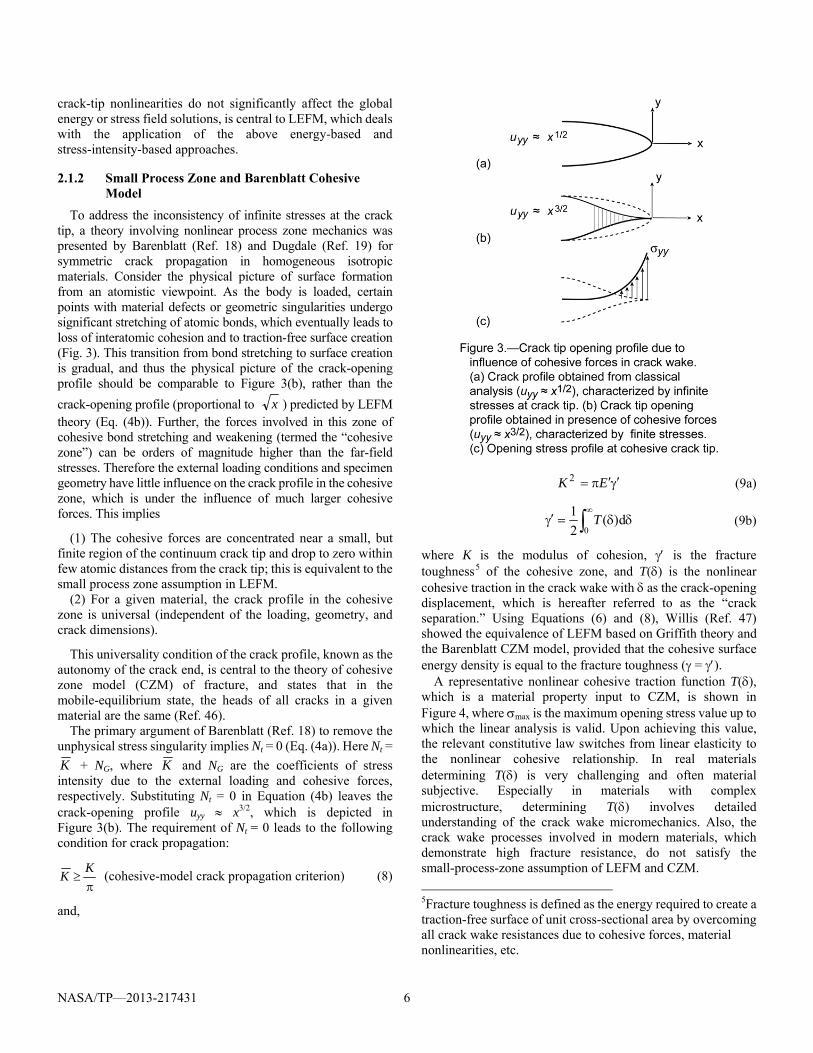
To address the inconsistency of infinite stresses at the crack tip, a theory involving nonlinear process zone mechanics was presented by Barenblatt (Ref. 18) and Dugdale (Ref. 19) for symmetric crack propagation in homogeneous isotropic materials. Consider the physical picture of surface formation from an atomistic viewpoint. As the body is loaded, certain points with material defects or geometric singularities undergo significant stretching of atomic bonds, which eventually leads to loss of interatomic cohesion and to traction-free surface creation (Fig. 3). This transition from bond stretching to surface creation is gradual, and thus the physical picture of the crack-opening profile should be comparable to Figure 3(b), rather than the
crack-opening profile (proportional to x ) predicted by LEFM theory (Eq. (4b)). Further, the forces involved in this zone of cohesive bond stretching and weakening (termed the “cohesive zone”) can be orders of magnitude higher than the far-field stresses. Therefore the external loading conditions and specimen geometry have little influence on the crack profile in the cohesive zone, which is under the influence of much larger cohesive forces. This implies
(1) The cohesive forces are concentrated near a small, but finite region of the continuum crack tip and drop to zero within few atomic distances from the crack tip; this is equivalent to the small process zone assumption in LEFM.
(2) For a given material, the crack profile in the cohesive zone is universal (independent of the loading, geometry, and crack dimensions).
This universality condition of the crack profile, known as the autonomy of the crack end, is central to the theory of cohesive zone model (CZM) of fracture, and states that in the mobile-equilibrium state, the heads of all cracks in a given material are the same (Ref. 46).
The primary argument of Barenblatt (Ref. 18) to remove the unphysical stress singularity implies Nt = 0 (Eq. (4a)). Here Nt =
K + NG, where K and NG are the coefficients of stress intensity due to the external loading and cohesive forces, respectively. Substituting Nt = 0 in Equation (4b) leaves the crack-opening profile uyy x3/2, which is depicted in Figure 3(b). The requirement of Nt = 0 leads to the following condition for crack propagation:
KK (cohesive-model crack propagation criterion) (8)
and,
EK 2 (9a)
d)(2
10
T (9b)
where K is the modulus of cohesion, is the fracture toughness5 of the cohesive zone, and T() is the nonlinear cohesive traction in the crack wake with as the crack-opening displacement, which is hereafter referred to as the “crack separation.” Using Equations (6) and (8), Willis (Ref. 47) showed the equivalence of LEFM based on Griffith theory and the Barenblatt CZM model, provided that the cohesive surface energy density is equal to the fracture toughness ( = ).
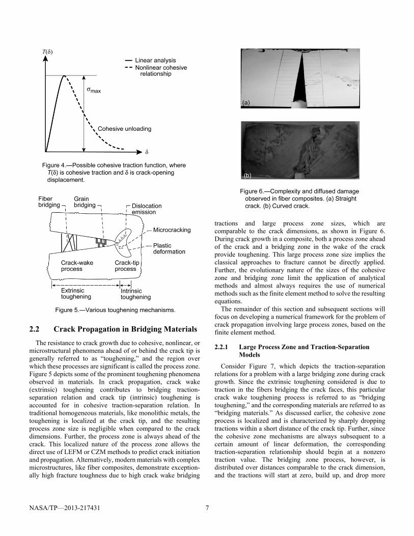
A representative nonlinear cohesive traction function T(), which is a material property input to CZM, is shown in Figure 4, where max is the maximum opening stress value up to which the linear analysis is valid. Upon achieving this value, the relevant constitutive law switches from linear elasticity to the nonlinear cohesive relationship. In real materials determining T() is very challenging and often material subjective. Especially in materials with complex microstructure, determining T() involves detailed understanding of the crack wake micromechanics. Also, the crack wake processes involved in modern materials, which demonstrate high fracture resistance, do not satisfy the small-process-zone assumption of LEFM and CZM.
5Fracture toughness is defined as the energy required to create a traction-free surface of unit cross-sectional area by overcoming all crack wake resistances due to cohesive forces, material nonlinearities, etc.
NASA/TP—2013-217431 7
2.2 Crack Propagation in Bridging Materials
The resistance to crack growth due to cohesive, nonlinear, or microstructural phenomena ahead of or behind the crack tip is generally referred to as “toughening,” and the region over which these processes are significant is called the process zone. Figure 5 depicts some of the prominent toughening phenomena observed in materials. In crack propagation, crack wake (extrinsic) toughening contributes to bridging traction- separation relation and crack tip (intrinsic) toughening is accounted for in cohesive traction-separation relation. In traditional homogeneous materials, like monolithic metals, the toughening is localized at the crack tip, and the resulting process zone size is negligible when compared to the crack dimensions. Further, the process zone is always ahead of the crack. This localized nature of the process zone allows the direct use of LEFM or CZM methods to predict crack initiation and propagation. Alternatively, modern materials with complex microstructures, like fiber composites, demonstrate exception-ally high fracture toughness due to high crack wake bridging
tractions and large process zone sizes, which are comparable to the crack dimensions, as shown in Figure 6. During crack growth in a composite, both a process zone ahead of the crack and a bridging zone in the wake of the crack provide toughening. This large process zone size implies the classical approaches to fracture cannot be directly applied. Further, the evolutionary nature of the sizes of the cohesive zone and bridging zone limit the application of analytical methods and almost always requires the use of numerical methods such as the finite element method to solve the resulting equations.
The remainder of this section and subsequent sections will focus on developing a numerical framework for the problem of crack propagation involving large process zones, based on the finite element method.
2.2.1 Large Process Zone and Traction-Separation Models
Consider Figure 7, which depicts the traction-separation relations for a problem with a large bridging zone during crack growth. Since the extrinsic toughening considered is due to traction in the fibers bridging the crack faces, this particular crack wake toughening process is referred to as “bridging toughening,” and the corresponding materials are referred to as “bridging materials.” As discussed earlier, the cohesive zone process is localized and is characterized by sharply dropping tractions within a short distance of the crack tip. Further, since the cohesive zone mechanisms are always subsequent to a certain amount of linear deformation, the corresponding traction-separation relationship should begin at a nonzero traction value. The bridging zone process, however, is distributed over distances comparable to the crack dimension, and the tractions will start at zero, build up, and drop more

NASA/TP—2013-217431 8
gradually.6 Now the challenge is to embed these two distinct
toughening processes into a numerical framework to produce physically consistent crack evolution. There are two possible approaches to this:
(1) Implement the two processes separately and use the corresponding traction-separation relations. So a point in the crack path begins with a cohesive traction relation and gradually transfers to having a bridging traction relation.
(2) Determine a cumulative traction-separation relation encompassing both these processes, and then treat the resultant nonlinear constitutive relation as a standard CZM T() relation. However, the chosen relation should be physically consistent, with the cohesive relation beginning at a finite traction, as shown in Figure 8(a). Alternatively, Figure 8(b) shows an inconsistent mixed traction relation, with the cohesive relation beginning at zero traction.
The latter approach is numerically more appealing and widely applied. However, such a cumulative traction-separation relation will depend on the problem and geometry as shown in Li et al. (Ref. 48). A detailed discussion of both the above approaches can be found in Sun and Jin (Ref. 49).
2.2.2 Cohesive Zone Model and Other Numerical Methods
Subsequent to the pioneering work by Barenblatt, the implementation of a CZM incorporating a finite element framework lay dormant until the work of Hillerborg, Modeer,
6It is noted that depending on the specific micromechanics, the starting traction in a bridging traction-separation relationship may or may not be zero.
and Petersson (Ref. 50). In parallel, other numerical techniques emerged to implement the LEFM methodology that found favor amongst practicing engineers. Therefore a brief review of LEFM-based numerical methods is presented here, before moving to the developments in CZM.
Among fracture parameters, the strain energy release rate has been increasingly used in conjunction with LEFM. It can be computed by the virtual crack closure technique (VCCT) (Ref. 51), in conjunction with finite element analysis. This method requires a preexisting mathematically sharp crack for initiation and conditions of small-scale yielding to hold. With negligible material nonlinearity at the crack tip (small process zone size), LEFM-based approaches have been proven to be effective in predicting crack initiation and subsequent growth (Refs. 51 to 57). Although as discussed earlier, during crack growth in composite materials and structures made of other quasi-brittle materials, the process zone size often may be larger than any characteristic length scale in the problem, leading to situations where the assumptions of LEFM cease to apply (Ref. 58). Several mechanisms like microcracking, fiber bridging, coalescence of voids, etc., can give rise to a process zone that is considerably larger than what is required for assumptions of LEFM to apply. A new length scale l* emerges that is related to a characteristic elastic modulus E, fracture toughness and cohesive strength max, defined as
2max
*2
El . If l* is larger than any characteristic length
scale in the problem, then the CZMs, which embed process zone mechanics through nonlinear traction-separation relationships across the crack faces become an important tool for analysis.
Subsequent to the work of Hillerborg, Modeer, and Petersson (Ref. 50), the crack band model, which incorporates a characteristic length l*, was introduced by Bazant and Oh (Ref. 59). Around the same time, CZM development in the form of nonlinear spring foundations was adopted by Ungsuwarungsri and Knauss (Ref. 23) to study crazing in polymers and by Song and Waas (Ref. 24) to study delamination fracture in laminated composites. Because of its
NASA/TP—2013-217431 9
versatility, CZM models became a popular choice for many fracture problems that were studied using a finite element framework as detailed in Pietruszczak and Mroz (Ref. 22); Xu and Needleman (Ref. 26); and Pandolfi, Krysl, and Ortiz (Ref. 60). In order to implement a CZM in its simplest form, two parameters are required: a fracture toughness and a cohesive strength. The choice of these parameters and how they are measured and/or calibrated depends on the problem that is being addressed. In general, the CZM parameters are system parameters and are related to the material system that is being studied. The fracture toughness can be obtained from coupon-level tests of the material system under study; for example, through compact tension specimen tests mentioned in Section 6.1. This measured toughness value in conjunction with a CZM simulation of the test can be used to back out the cohesive strength. Alternatively, both the toughness and strength can be measured from coupon-level tests for subsequent use in prediction of crack growth in other structural configurations. In a CZM, an existing crack starts to grow when the stress at the crack tip attains the cohesive strength and when there is sufficient energy supplied from the system to create a new cracked area associated with the advancing crack. Thus, unlike LEFM, which requires one parameter because the crack growth is predicted from strictly global measures, a CZM strategy requires two local parameters for predicting both crack initiation and evolution. A cohesive law combines fracture energy and cohesive strength to describe the resistance offered to crack advancement within the cohesive zone. Various postulated forms of cohesive laws (such as triangular, exponential, trapezoidal, multisection, etc.) have been attempted in conjunction with CZM (Refs. 48 and 61 to 63). These studies, however, have shown that the form of the phenomenological cohesive law are less important than the well-posed implementation, when CZM is used with finite element analysis. However, a major drawback of CZM-based methods is the fact the intended crack path must be known a priori in order to place the CZM elements appropriately in a finite element mesh (Sec. 4.1.1). Thus, the CZM strategies are not practical for predicting crack growth in a solid under general loading conditions.
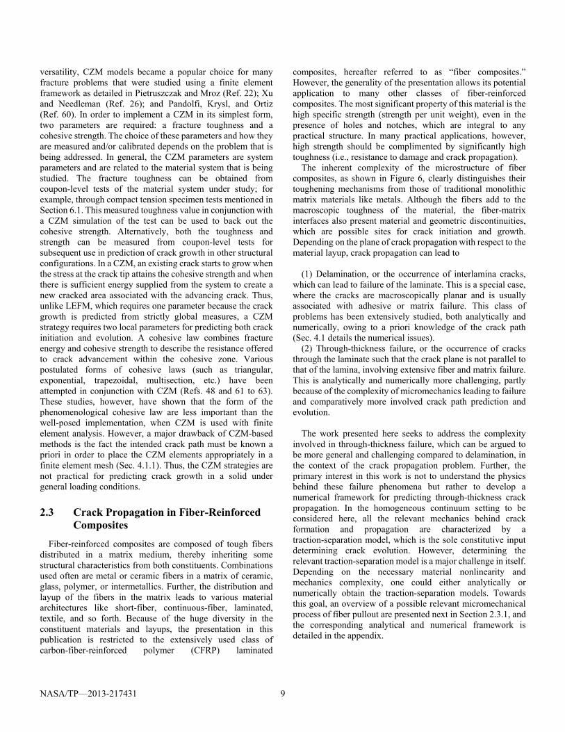
2.3 Crack Propagation in Fiber-Reinforced Composites
Fiber-reinforced composites are composed of tough fibers distributed in a matrix medium, thereby inheriting some structural characteristics from both constituents. Combinations used often are metal or ceramic fibers in a matrix of ceramic, glass, polymer, or intermetallics. Further, the distribution and layup of the fibers in the matrix leads to various material architectures like short-fiber, continuous-fiber, laminated, textile, and so forth. Because of the huge diversity in the constituent materials and layups, the presentation in this publication is restricted to the extensively used class of carbon-fiber-reinforced polymer (CFRP) laminated
composites, hereafter referred to as “fiber composites.” However, the generality of the presentation allows its potential application to many other classes of fiber-reinforced composites. The most significant property of this material is the high specific strength (strength per unit weight), even in the presence of holes and notches, which are integral to any practical structure. In many practical applications, however, high strength should be complimented by significantly high toughness (i.e., resistance to damage and crack propagation).
The inherent complexity of the microstructure of fiber composites, as shown in Figure 6, clearly distinguishes their toughening mechanisms from those of traditional monolithic matrix materials like metals. Although the fibers add to the macroscopic toughness of the material, the fiber-matrix interfaces also present material and geometric discontinuities, which are possible sites for crack initiation and growth. Depending on the plane of crack propagation with respect to the material layup, crack propagation can lead to
(1) Delamination, or the occurrence of interlamina cracks, which can lead to failure of the laminate. This is a special case, where the cracks are macroscopically planar and is usually associated with adhesive or matrix failure. This class of problems has been extensively studied, both analytically and numerically, owing to a priori knowledge of the crack path (Sec. 4.1 details the numerical issues).
(2) Through-thickness failure, or the occurrence of cracks through the laminate such that the crack plane is not parallel to that of the lamina, involving extensive fiber and matrix failure. This is analytically and numerically more challenging, partly because of the complexity of micromechanics leading to failure and comparatively more involved crack path prediction and evolution.
The work presented here seeks to address the complexity
involved in through-thickness failure, which can be argued to be more general and challenging compared to delamination, in the context of the crack propagation problem. Further, the primary interest in this work is not to understand the physics behind these failure phenomena but rather to develop a numerical framework for predicting through-thickness crack propagation. In the homogeneous continuum setting to be considered here, all the relevant mechanics behind crack formation and propagation are characterized by a traction-separation model, which is the sole constitutive input determining crack evolution. However, determining the relevant traction-separation model is a major challenge in itself. Depending on the necessary material nonlinearity and mechanics complexity, one could either analytically or numerically obtain the traction-separation models. Towards this goal, an overview of a possible relevant micromechanical process of fiber pullout are presented next in Section 2.3.1, and the corresponding analytical and numerical framework is detailed in the appendix.
NASA/TP—2013-217431 10
2.3.1 Micromechanics
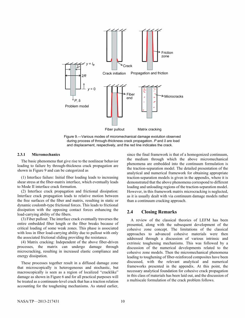
The basic phenomena that give rise to the nonlinear behavior leading to failure by through-thickness crack propagation are shown in Figure 9 and can be categorized as
(1) Interface failure: Initial fiber loading leads to increasing shear stress at the fiber-matrix interface, which eventually leads to Mode II interface crack formation.
(2) Interface crack propagation and frictional dissipation: Interface crack propagation leads to relative motion between the free surfaces of the fiber and matrix, resulting in static or dynamic coulomb-type frictional forces. This leads to frictional dissipation with the opposing contact forces enhancing the load-carrying ability of the fibers.
(3) Fiber pullout: The interface crack eventually traverses the entire embedded fiber length or the fiber breaks because of critical loading of some weak zones. This phase is associated with loss in fiber load-carrying ability due to pullout with only the associated frictional sliding providing the resistance.
(4) Matrix cracking: Independent of the above fiber-driven processes, the matrix can undergo damage through microcracking, resulting in increased elastic compliance and energy dissipation.
These processes together result in a diffused damage zone that microscopically is heterogeneous and stochastic, but macroscopically is seen as a region of localized “cracklike” damage as shown in Figure 6 and for all practical purposes will be treated as a continuum-level crack that has a traction relation accounting for the toughening mechanisms. As stated earlier,
since the final framework is that of a homogenized continuum, the medium through which the above micromechanical phenomena are embedded into the continuum formulation is the traction-separation model. The detailed presentation of the analytical and numerical framework for obtaining appropriate traction-separation models is given in the appendix, where it is demonstrated that the above phenomena correspond to different loading and unloading regions of the traction-separation model. However, in this framework matrix microcracking is neglected, as it is usually dealt with via continuum damage models rather than a continuum cracking approach.
2.4 Closing Remarks
A review of the classical theories of LEFM has been presented, along with the subsequent development of the cohesive zone concept. The limitations of the classical approaches to advanced cohesive materials were then addressed through a discussion of various intrinsic and extrinsic toughening mechanisms. This was followed by a discussion of the numerical developments related to the cohesive zone models. Then the micromechanical phenomena leading to toughening of fiber-reinforced composites have been discussed, with the relevant analytical and numerical frameworks presented in the appendix. At this point, the necessary analytical foundation for cohesive crack propagation in this class of materials has been laid out, and the discussion of a multiscale formulation of the crack problem follows.
NASA/TP—2013-217431 11
3.0 Multiscale Framework and Variational Formulation
The Variational Multiscale Cohesive Method (VMCM) is presented in this section.
3.1 Background and Variational Multiscale Concept
Physical processes spread across space and time scales are ubiquitous. Often the complexity involved in understanding these phenomena is nontrivial, and one has to resort to empirical, phenomenological models to make them more approachable. Further, the fidelity of these models is geared towards conforming to the ultimate framework (analytical or numerical) used to simulate the physical phenomena. Thus, there is a constant drive towards development of better scale-aware analytical and numerical formulations. Focusing attention on the related numerical developments, it is common knowledge that straightforward application of the widely used Galerkin’s method employing standard basis functions (Fourier series, finite elements, etc.) is not a robust approach in the presence of multiscale phenomena as certain far-scale or subscale processes are not sufficiently and objectively resolved (demonstrated in Sec. 4.1), which can give rise to fictitious length and time scales in the solution. To address this issue of disparate scales in numerical schemes, a new computational paradigm called the variational multiscale method (hereafter referred to as “VMM”) was introduced by Hughes (Ref. 38). Initially developed to address the question of “intrinsic time scale” in stabilized methods like Galerkin/least-squares and streamline upwind/Petrov-Galerkin (Ref. 64), the VMM approach resulted in giving a unifying perspective of many previous numerical frameworks that address various subscale phenomena. One such effort from which this publication draws inspiration is by Garikipati and Hughes (Refs. 39 and 65), in which the process of strain localization as a multiscale problem was presented, and a unifying picture of various scale- regularization-based formulations like the composite damage model, crack band model and nonlocal strain model were discussed. The point of departure in the current work is the characterization of displacement discontinuity due to cracks as a fine scale and its subsequent coupling to the continuum fields via micromechanical surface laws. The physical picture of the broad classification of multiscale problems introduced in Hughes (Ref. 38) and Hughes et al. (Ref. 64) is presented as a background to the presentation in this work.
3.1.1 Grid-Scale Model: Large-Scale and Small-Scale
Consider the exterior problem of the Helmholtz operator, which models wave propagation in free space due to a localized
source, stated as follows: For 3 , find :u
such that for given ggf :,: , and
hh : ,
infu (10a)
ggu on (10b)
hn ikhu on, (10c)
condition)radiation d(Sommerfel),(lim 0
ikuur rr
(10d)
where
Ω domain volume
real space
u complex scalar function (potential)
complex space
f forcing function
g Dirichlet boundary condition value
domain surface
h Neumann boundary condition value
Helmholtz operator, 2k
Laplace operator
k wave number, k
n surface normal r radial coordinate
Also let the following decomposition of the boundary be admitted:
hg (11a)
hg 0 (11b)
From a numerical standpoint, Equation (10d) presents a problem, as this infinite-domain boundary condition cannot be handled in conventional bounded-domain discretization methods like finite elements. So a unique domain and field decomposition is introduced to solve this problem. The decomposition is as follows:
(12a)
0 (12b)
uuu (12c)
ion)decomposit additive(disjoint 0|,0| uu (12d)

NASA/TP—2013-217431 12
where R is the boundary between and as shown in Figure 10. Equation (12d) results in the solution field u being decomposed into a far-field u and a near-field u . The far-field u is numerically “unresolvable” because of the boundary-condition at infinity as in Equation (10d). So the approach suggested in Hughes (Ref. 38) is to analytically determine u in the following exterior Dirichlet problem:
infu (13a)
condition)y (continuitRonuu (13b)
0),(lim
uikur rr
(13c)
and then use this solution to embed its effect into the following bounded domain problem for u through the continuity condition Equation (13b), which manifests as Equation (14d):
infu (14a)
ggu on (14b)
hn ikhu on, (14c)
Rn uMu on, (14d)
Equation (14d) is called a Dirichlet-to-Neumann condition
(Ref. 38) on the boundary R that separates from . M is an integral operator obtained by solving Equations (13) using a Green’s function approach; it embeds the far-field phenomena into the near-field problem. The boundary-value problem in Equations (15) is now solvable using a finite-domain numerical formulation like finite elements. The field decomposition in Equation (12c) can be interpreted as a multiscale problem, with u representing the far-field large scales and u representing the near-field small scales.
Remark: Since herein the decomposition was primarily at the domain level (or in numerical
parlance, at the grid level) into and , one may refer to this as a “grid-scale” model. This will help distinguish this model from the more useful and physically motivated “subgrid-scale” model presented in the following subsection.
3.1.2 Subgrid-Scale Model: Coarse-Scale and Fine-Scale
Now consider an abstract Dirichlet problem: For 3 , find :u such that for given R:f and
:g ,
infu (15a)
ongu (15b)
where is a general nonsymmetric operator. Also, keeping in
mind the numerical scheme that will be used in Section 4.0 “Finite Element Implementation,” a variational treatment is considered for this problem:
For S H1() and V H1(), where H1() is the Sobolov space of square integrable functions with square integrable derivatives, find u S = vv = g on such that w V = vv = 0 on ,
VwfVuw dd (16a)
),(),(or fwuwa (16b)
where a represents the bilinear form. The physical picture of the field u being addressed here is
shown in Figure 11. Now from a numerical standpoint, fields with such “fine” variations pose a difficulty, as the resolution of these fields becomes subjective with respect to the numerical discretization. This is because these variations occur on physical length scales that are usually smaller than the size of the numerical grid, and it is for this reason that the numerical treatment of problems under this class requires a subgrid-scale model. Often in physical phenomena like turbulent flow, strain localization, phase separation, and crack formation, these fluctuations7 are at such small length scales that the optimal discretization required in a standard Galerkin implementation is prohibitively expensive, or even impossible. For such cases, 7In crack propagation, which is the problem of interest in this work, the fine-scale field u is not oscillatory, but a discontinuity. For the abstract presentation in this section, the more general oscillatory picture of fine-scale variations is considered.
NASA/TP—2013-217431 13
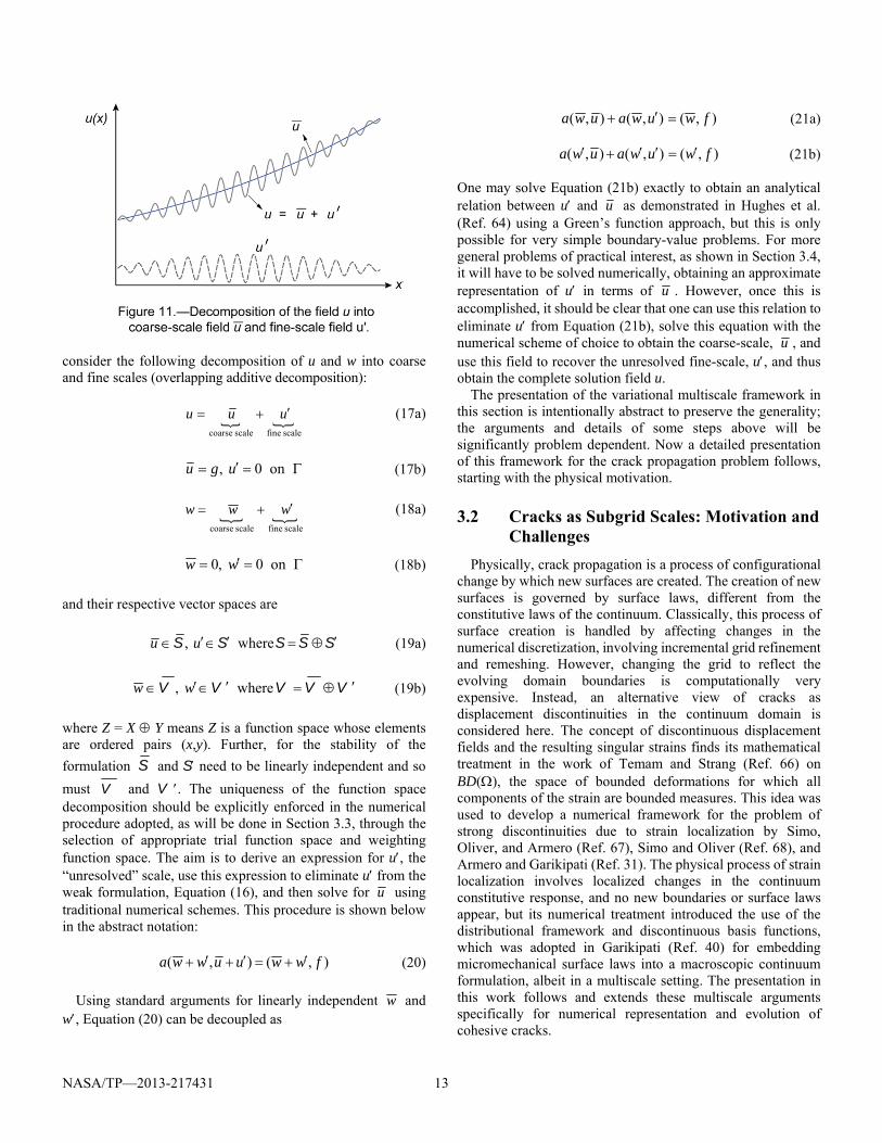
consider the following decomposition of u and w into coarse and fine scales (overlapping additive decomposition):
scale finescale coarse
uuu (17a)
on0, ugu (17b)
scale finescale coarse
www (18a)
on0,0 ww (18b)
and their respective vector spaces are
SSSSS where, uu (19a)
VVVVV where, ww (19b)
where Z = X Y means Z is a function space whose elements are ordered pairs (x,y). Further, for the stability of the
formulation S and S need to be linearly independent and so
must V and V . The uniqueness of the function space decomposition should be explicitly enforced in the numerical procedure adopted, as will be done in Section 3.3, through the selection of appropriate trial function space and weighting function space. The aim is to derive an expression for u, the “unresolved” scale, use this expression to eliminate u from the weak formulation, Equation (16), and then solve for u using traditional numerical schemes. This procedure is shown below in the abstract notation:
),(),( fwwuuwwa (20)
Using standard arguments for linearly independent w and w, Equation (20) can be decoupled as
),(),(),( fwuwauwa (21a)
),(),(),( fwuwauwa (21b)
One may solve Equation (21b) exactly to obtain an analytical relation between u and u as demonstrated in Hughes et al. (Ref. 64) using a Green’s function approach, but this is only possible for very simple boundary-value problems. For more general problems of practical interest, as shown in Section 3.4, it will have to be solved numerically, obtaining an approximate representation of u in terms of u . However, once this is accomplished, it should be clear that one can use this relation to eliminate u from Equation (21b), solve this equation with the numerical scheme of choice to obtain the coarse-scale, u , and use this field to recover the unresolved fine-scale, u, and thus obtain the complete solution field u.
The presentation of the variational multiscale framework in this section is intentionally abstract to preserve the generality; the arguments and details of some steps above will be significantly problem dependent. Now a detailed presentation of this framework for the crack propagation problem follows, starting with the physical motivation.
3.2 Cracks as Subgrid Scales: Motivation and Challenges
Physically, crack propagation is a process of configurational change by which new surfaces are created. The creation of new surfaces is governed by surface laws, different from the constitutive laws of the continuum. Classically, this process of surface creation is handled by affecting changes in the numerical discretization, involving incremental grid refinement and remeshing. However, changing the grid to reflect the evolving domain boundaries is computationally very expensive. Instead, an alternative view of cracks as displacement discontinuities in the continuum domain is considered here. The concept of discontinuous displacement fields and the resulting singular strains finds its mathematical treatment in the work of Temam and Strang (Ref. 66) on BD(), the space of bounded deformations for which all components of the strain are bounded measures. This idea was used to develop a numerical framework for the problem of strong discontinuities due to strain localization by Simo, Oliver, and Armero (Ref. 67), Simo and Oliver (Ref. 68), and Armero and Garikipati (Ref. 31). The physical process of strain localization involves localized changes in the continuum constitutive response, and no new boundaries or surface laws appear, but its numerical treatment introduced the use of the distributional framework and discontinuous basis functions, which was adopted in Garikipati (Ref. 40) for embedding micromechanical surface laws into a macroscopic continuum formulation, albeit in a multiscale setting. The presentation in this work follows and extends these multiscale arguments specifically for numerical representation and evolution of cohesive cracks.
NASA/TP—2013-217431 14
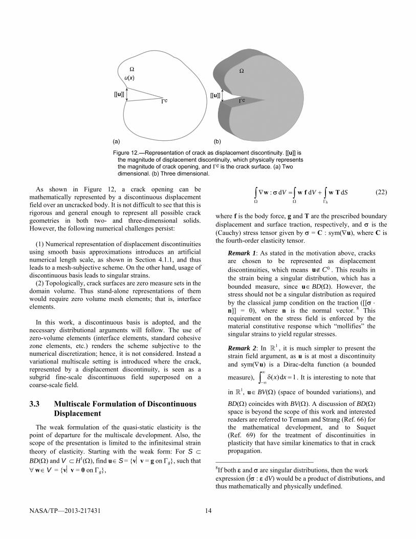
As shown in Figure 12, a crack opening can be mathematically represented by a discontinuous displacement field over an uncracked body. It is not difficult to see that this is rigorous and general enough to represent all possible crack geometries in both two- and three-dimensional solids. However, the following numerical challenges persist:
(1) Numerical representation of displacement discontinuities
using smooth basis approximations introduces an artificial numerical length scale, as shown in Section 4.1.1, and thus leads to a mesh-subjective scheme. On the other hand, usage of discontinuous basis leads to singular strains.
(2) Topologically, crack surfaces are zero measure sets in the domain volume. Thus stand-alone representations of them would require zero volume mesh elements; that is, interface elements.
In this work, a discontinuous basis is adopted, and the
necessary distributional arguments will follow. The use of zero-volume elements (interface elements, standard cohesive zone elements, etc.) renders the scheme subjective to the numerical discretization; hence, it is not considered. Instead a variational multiscale setting is introduced where the crack, represented by a displacement discontinuity, is seen as a subgrid fine-scale discontinuous field superposed on a coarse-scale field.
3.3 Multiscale Formulation of Discontinuous Displacement
The weak formulation of the quasi-static elasticity is the point of departure for the multiscale development. Also, the scope of the presentation is limited to the infinitesimal strain theory of elasticity. Starting with the weak form: For S BD() and V H1(), find u S = vv = g on g, such that w V = vv = 0 on g,
h
SVV ddd: Twfww (22)
where f is the body force, g and T are the prescribed boundary displacement and surface traction, respectively, and is the (Cauchy) stress tensor given by = C : sym(u), where C is the fourth-order elasticity tensor.
Remark 1: As stated in the motivation above, cracks are chosen to be represented as displacement discontinuities, which means 0Cu . This results in the strain being a singular distribution, which has a bounded measure, since u BD(). However, the stress should not be a singular distribution as required by the classical jump condition on the traction ([[ n]] = 0), where n is the normal vector. 8 This requirement on the stress field is enforced by the material constitutive response which “mollifies” the singular strains to yield regular stresses.
Remark 2: In 1 , it is much simpler to present the strain field argument, as u is at most a discontinuity and sym(u) is a Dirac-delta function (a bounded
measure), 1d)(
xx . It is interesting to note that
in 1, u BV() (space of bounded variations), and
BD() coincides with BV(). A discussion of BD() space is beyond the scope of this work and interested readers are referred to Temam and Strang (Ref. 66) for the mathematical development, and to Suquet (Ref. 69) for the treatment of discontinuities in plasticity that have similar kinematics to that in crack propagation.
8If both and are singular distributions, then the work expression ( : dV) would be a product of distributions, and thus mathematically and physically undefined.
NASA/TP—2013-217431 15
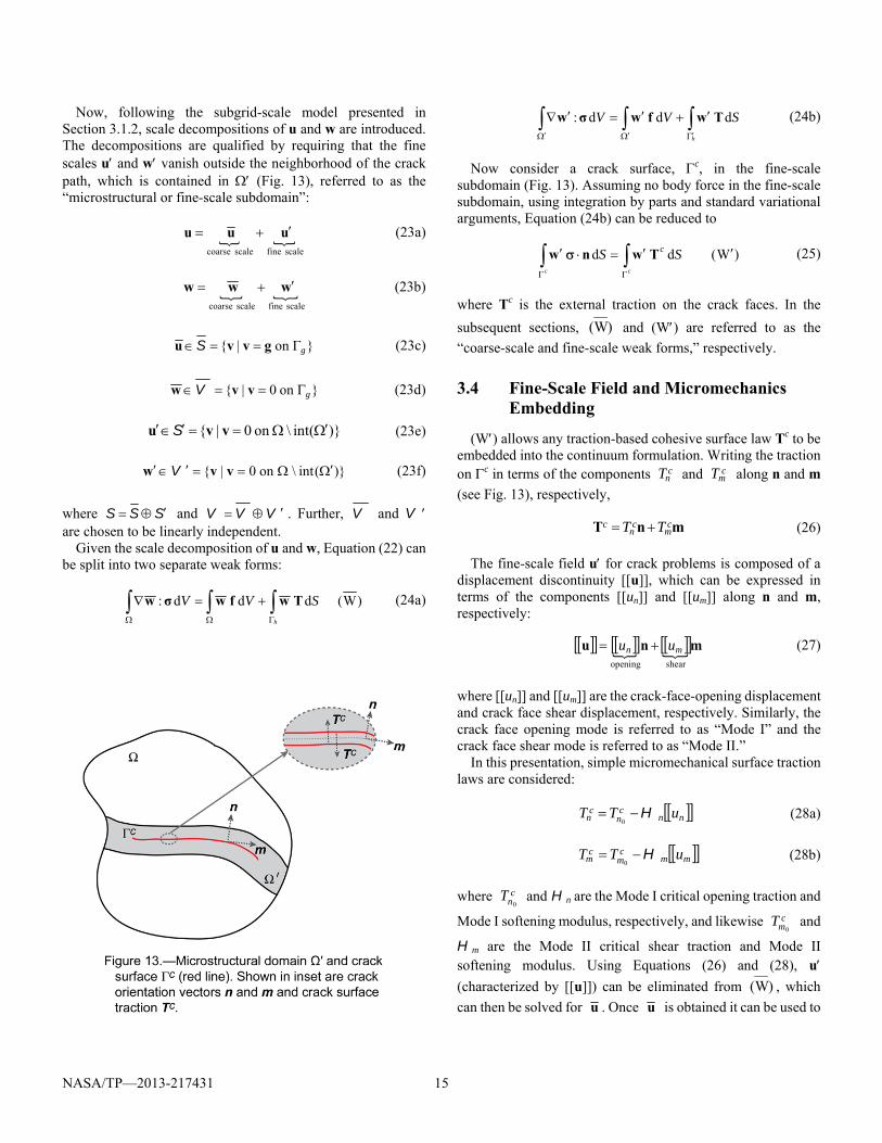
Now, following the subgrid-scale model presented in Section 3.1.2, scale decompositions of u and w are introduced. The decompositions are qualified by requiring that the fine scales u and w vanish outside the neighborhood of the crack path, which is contained in (Fig. 13), referred to as the “microstructural or fine-scale subdomain”:
scale finescale coarse
uuu (23a)
scale finescale coarse
www (23b)
on| g gvvu S (23c)
on0| g vvw V (23d)
)(int\on0| vvu S (23e)
)(int\on0| vvw V (23f)
where SSS and VVV . Further, V and V are chosen to be linearly independent.
Given the scale decomposition of u and w, Equation (22) can be split into two separate weak forms:
)W(ddd:
h
SVV Twfwσw (24a)
h
SVV ddd: Twfwσw (24b)
Now consider a crack surface, c, in the fine-scale subdomain (Fig. 13). Assuming no body force in the fine-scale subdomain, using integration by parts and standard variational arguments, Equation (24b) can be reduced to
)W(dd cc
SS cTwnw (25)
where Tc is the external traction on the crack faces. In the
subsequent sections, )W( and (W) are referred to as the
“coarse-scale and fine-scale weak forms,” respectively.
3.4 Fine-Scale Field and Micromechanics Embedding
(W) allows any traction-based cohesive surface law Tc to be embedded into the continuum formulation. Writing the traction on c in terms of the components c
nT and cmT along n and m
(see Fig. 13), respectively,
mnT cm
cn
c TT (26)
The fine-scale field u for crack problems is composed of a displacement discontinuity [[u]], which can be expressed in terms of the components [[un]] and [[um]] along n and m, respectively:
mnushearopening
mn uu (27)
where [[un]] and [[um]] are the crack-face-opening displacement and crack face shear displacement, respectively. Similarly, the crack face opening mode is referred to as “Mode I” and the crack face shear mode is referred to as “Mode II.”
In this presentation, simple micromechanical surface traction laws are considered:
nnc
nc
n uTT H0
(28a)
mmc
mc
m uTT H0
(28b)
where cnT
0 and Hn are the Mode I critical opening traction and
Mode I softening modulus, respectively, and likewise cmT
0 and
Hm are the Mode II critical shear traction and Mode II softening modulus. Using Equations (26) and (28), u (characterized by [[u]]) can be eliminated from )W( , which
can then be solved for u . Once u is obtained it can be used to
NASA/TP—2013-217431 16
recover u, thereby determining the complete displacement field. Developing this procedure in a finite element setting is the focus of Section 4.0.
3.5 Closing Remarks
In this section, the necessary multiscale background was introduced, and its application to crack problems was discussed. The approach consists of treating the discontinuous displacement field in crack problems in a distributional sense and identifying the singular character of the strains. This treatment was then developed to obtain the weak formulation of the coarse- and fine-scale problems. Then it was shown that the fine-scale problem can be used as a vehicle to embed the cohesive surface laws into the continuum formulation. Using this as a point of departure, the necessary numerical framework is developed in the subsequent section.
4.0 Finite Element Implementation
With the multiscale concepts laid out, and explicit weak form expression derived, attention is now turned to the numerical implementation. In this section, the multiscale methodology is cast into a finite element formulation, and the necessary numerical framework, referred to as the “Variational Multiscale Cohesive Method” (VMCM), is developed. First, a brief discussion of the limitations of standard finite element basis functions is presented in Section 4.1. Then the necessary discontinuous shape functions are presented in Section 4.2. These enhanced basis functions were first introduced in the works of Simo, Oliver, and Armero (Ref. 67); Armero and Garikipati (Ref. 31); and Garikipati (Ref. 70). Comparable, but significantly different, discontinuous basis functions are used in the extended finite element method (XFEM) introduced in Moes, Dolbow, and Belytschko (Ref. 34) and applied to cohesive crack propagation in Moes and Belytschko (Ref. 35), and in the related basis functions based on the partition of unity method (PUM) employed in Wells and Sluys (Ref. 37). After the multiscale shape function discussion, the finite dimensional weak formulation is presented in Section 4.3 and followed by the iterative solution procedure in Section 4.4. Lastly, in Section 4.5, the closing remarks and a brief comparison of the present multiscale framework with the PUM is presented.
4.1 Mesh Sensitivity of Standard Galerkin Basis
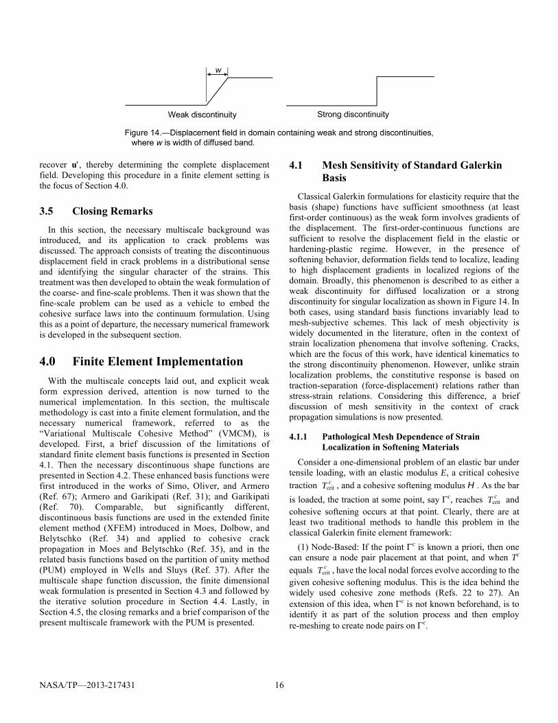
Classical Galerkin formulations for elasticity require that the basis (shape) functions have sufficient smoothness (at least first-order continuous) as the weak form involves gradients of the displacement. The first-order-continuous functions are sufficient to resolve the displacement field in the elastic or hardening-plastic regime. However, in the presence of softening behavior, deformation fields tend to localize, leading to high displacement gradients in localized regions of the domain. Broadly, this phenomenon is described to as either a weak discontinuity for diffused localization or a strong discontinuity for singular localization as shown in Figure 14. In both cases, using standard basis functions invariably lead to mesh-subjective schemes. This lack of mesh objectivity is widely documented in the literature, often in the context of strain localization phenomena that involve softening. Cracks, which are the focus of this work, have identical kinematics to the strong discontinuity phenomenon. However, unlike strain localization problems, the constitutive response is based on traction-separation (force-displacement) relations rather than stress-strain relations. Considering this difference, a brief discussion of mesh sensitivity in the context of crack propagation simulations is now presented.
4.1.1 Pathological Mesh Dependence of Strain Localization in Softening Materials
Consider a one-dimensional problem of an elastic bar under tensile loading, with an elastic modulus E, a critical cohesive
traction cTcrit , and a cohesive softening modulus H. As the bar
is loaded, the traction at some point, say c, reaches cTcrit and cohesive softening occurs at that point. Clearly, there are at least two traditional methods to handle this problem in the classical Galerkin finite element framework:
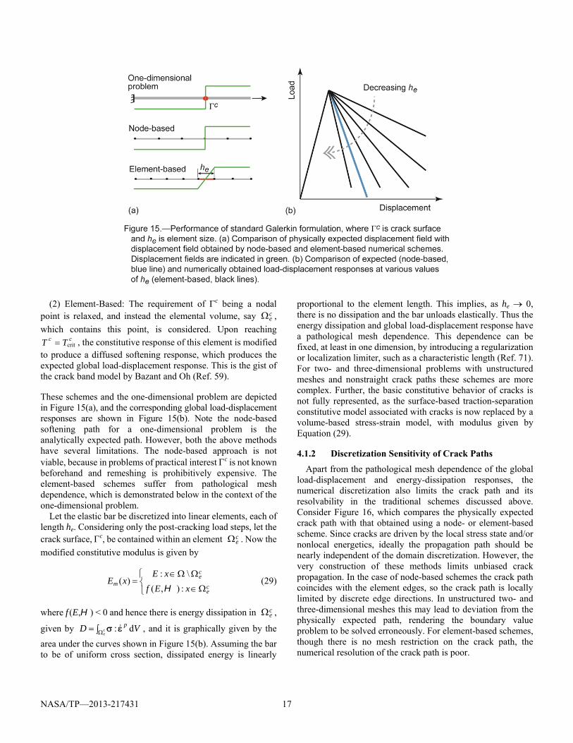
(1) Node-Based: If the point c is known a priori, then one can ensure a node pair placement at that point, and when Tc
equals cTcrit , have the local nodal forces evolve according to the given cohesive softening modulus. This is the idea behind the widely used cohesive zone methods (Refs. 22 to 27). An extension of this idea, when c is not known beforehand, is to identify it as part of the solution process and then employ re-meshing to create node pairs on c.
NASA/TP—2013-217431 17
(2) Element-Based: The requirement of c being a nodal point is relaxed, and instead the elemental volume, say c
e ,
which contains this point, is considered. Upon reaching cc TT crit , the constitutive response of this element is modified
to produce a diffused softening response, which produces the expected global load-displacement response. This is the gist of the crack band model by Bazant and Oh (Ref. 59).
These schemes and the one-dimensional problem are depicted in Figure 15(a), and the corresponding global load-displacement responses are shown in Figure 15(b). Note the node-based softening path for a one-dimensional problem is the analytically expected path. However, both the above methods have several limitations. The node-based approach is not viable, because in problems of practical interest c is not known beforehand and remeshing is prohibitively expensive. The element-based schemes suffer from pathological mesh dependence, which is demonstrated below in the context of the one-dimensional problem.
Let the elastic bar be discretized into linear elements, each of length he. Considering only the post-cracking load steps, let the crack surface, c, be contained within an element c
e . Now the
modified constitutive modulus is given by
ce
ce
m xEfxE
xE:),(
\:)(
H (29)
where f (E,H) < 0 and hence there is energy dissipation in ce ,
given by VD pce
d: , and it is graphically given by the
area under the curves shown in Figure 15(b). Assuming the bar to be of uniform cross section, dissipated energy is linearly
proportional to the element length. This implies, as he 0, there is no dissipation and the bar unloads elastically. Thus the energy dissipation and global load-displacement response have a pathological mesh dependence. This dependence can be fixed, at least in one dimension, by introducing a regularization or localization limiter, such as a characteristic length (Ref. 71). For two- and three-dimensional problems with unstructured meshes and nonstraight crack paths these schemes are more complex. Further, the basic constitutive behavior of cracks is not fully represented, as the surface-based traction-separation constitutive model associated with cracks is now replaced by a volume-based stress-strain model, with modulus given by Equation (29).
4.1.2 Discretization Sensitivity of Crack Paths
Apart from the pathological mesh dependence of the global load-displacement and energy-dissipation responses, the numerical discretization also limits the crack path and its resolvability in the traditional schemes discussed above. Consider Figure 16, which compares the physically expected crack path with that obtained using a node- or element-based scheme. Since cracks are driven by the local stress state and/or nonlocal energetics, ideally the propagation path should be nearly independent of the domain discretization. However, the very construction of these methods limits unbiased crack propagation. In the case of node-based schemes the crack path coincides with the element edges, so the crack path is locally limited by discrete edge directions. In unstructured two- and three-dimensional meshes this may lead to deviation from the physically expected path, rendering the boundary value problem to be solved erroneously. For element-based schemes, though there is no mesh restriction on the crack path, the numerical resolution of the crack path is poor.
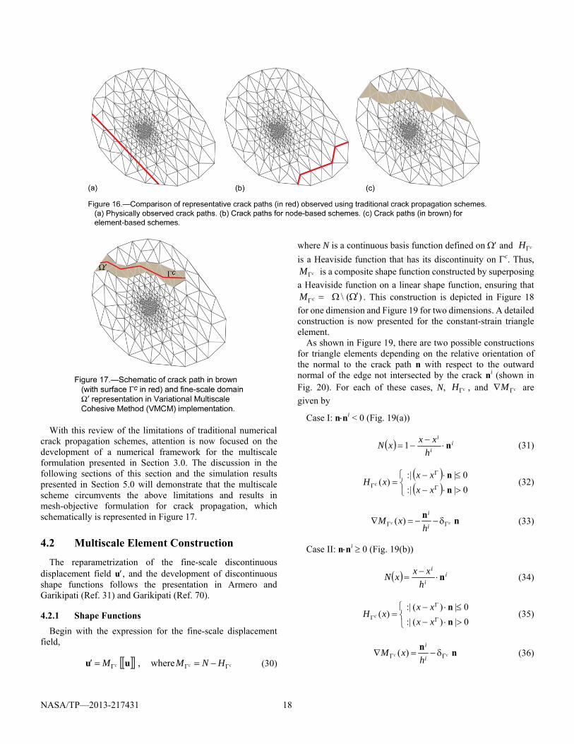
NASA/TP—2013-217431 18
With this review of the limitations of traditional numerical crack propagation schemes, attention is now focused on the development of a numerical framework for the multiscale formulation presented in Section 3.0. The discussion in the following sections of this section and the simulation results presented in Section 5.0 will demonstrate that the multiscale scheme circumvents the above limitations and results in mesh-objective formulation for crack propagation, which schematically is represented in Figure 17.
4.2 Multiscale Element Construction
The reparametrization of the fine-scale discontinuous displacement field u, and the development of discontinuous shape functions follows the presentation in Armero and Garikipati (Ref. 31) and Garikipati (Ref. 70).
4.2.1 Shape Functions
Begin with the expression for the fine-scale displacement field,
ccc HNMM where,uu (30)
where N is a continuous basis function defined on and cH
is a Heaviside function that has its discontinuity on c. Thus, cM is a composite shape function constructed by superposing
a Heaviside function on a linear shape function, ensuring that)(\ cM . This construction is depicted in Figure 18
for one dimension and Figure 19 for two dimensions. A detailed construction is now presented for the constant-strain triangle element.
As shown in Figure 19, there are two possible constructions for triangle elements depending on the relative orientation of the normal to the crack path n with respect to the outward normal of the edge not intersected by the crack ni (shown in Fig. 20). For each of these cases, N, cH , and cM are
given by
Case I: nni < 0 (Fig. 19(a))
ii
i
hxxxN n
1 (31)
0|:|
0|:|)(
n
n
xxxx
xH c (32)
nn
cc i
i
hxM )( (33)
Case II: nni 0 (Fig. 19(b))
ii
i
hxxxN n
(34)
0|)(:|
0|)(:|)(
n
n
xxxx
xH c (35)
nn
cc i
i
hxM )( (36)
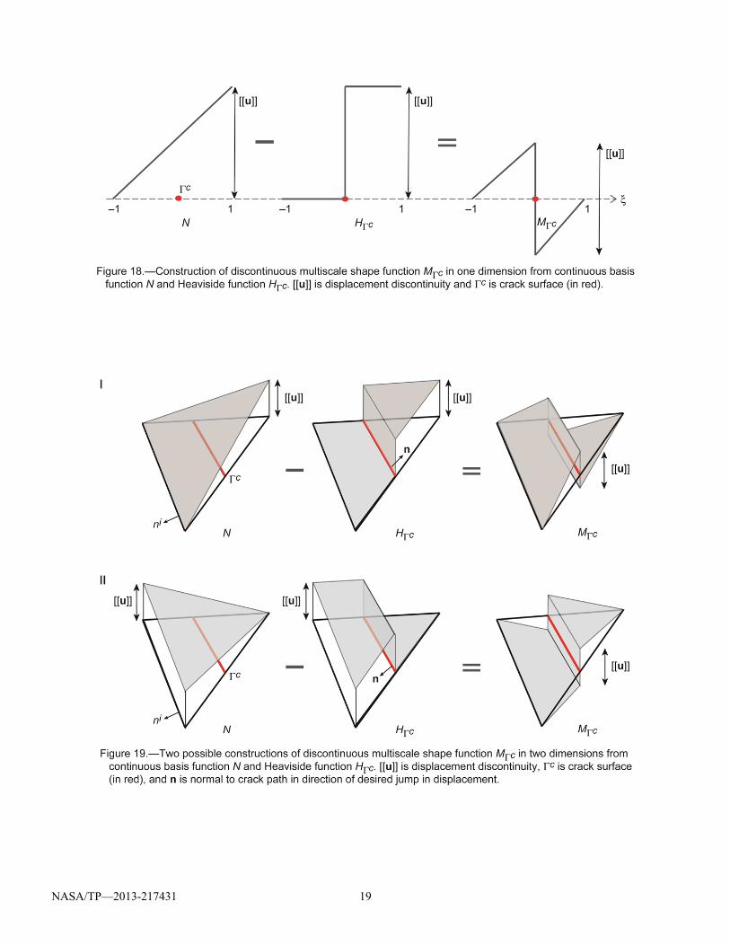
NASA/TP—2013-217431 19
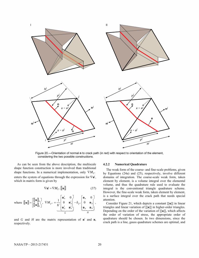
NASA/TP—2013-217431 20
As can be seen from the above description, the multiscale shape function construction is more involved than traditional shape functions. In a numerical implementation, only cM
enters the system of equations through the expression for u, which in matrix form is given by
uu cM (37)
where
y
x
u
uu ,
H
xy
y
x
G
ix
iy
iy
ix
i cch
M
nn
n
n
nn
n
n
0
0
0
01
,
and G and H are the matrix representation of ni and n, respectively.
4.2.2 Numerical Quadrature
The weak form of the coarse- and fine-scale problems, given by Equations (24a) and (25), respectively, involve different domains of integration. The coarse-scale weak form, taken element by element, is a volume integral over the elemental volume, and thus the quadrature rule used to evaluate the integral is the conventional triangle quadrature scheme. However, the fine-scale weak form, taken element by element, is a surface integral over the crack path that needs special attention.
Consider Figure 21, which depicts a constant [[u]] in linear triangles and linear variation of [[u]] in higher-order triangles. Depending on the order of the variation of [[u]], which affects the order of variation of stress, the appropriate order of quadrature should be chosen. In two dimensions, since the crack path is a line, gauss quadrature schemes are optimal, and
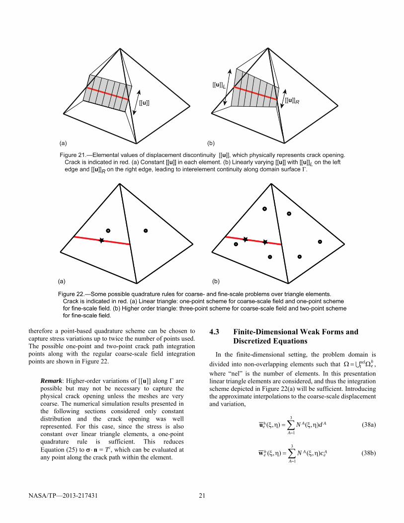
NASA/TP—2013-217431 21
therefore a point-based quadrature scheme can be chosen to capture stress variations up to twice the number of points used. The possible one-point and two-point crack path integration points along with the regular coarse-scale field integration points are shown in Figure 22.
Remark: Higher-order variations of [[u]] along are possible but may not be necessary to capture the physical crack opening unless the meshes are very coarse. The numerical simulation results presented in the following sections considered only constant distribution and the crack opening was well represented. For this case, since the stress is also constant over linear triangle elements, a one-point quadrature rule is sufficient. This reduces Equation (25) to n = Tc, which can be evaluated at any point along the crack path within the element.
4.3 Finite-Dimensional Weak Forms and Discretized Equations
In the finite-dimensional setting, the problem domain is
divided into non-overlapping elements such that he nel
1 ,
where “nel” is the number of elements. In this presentation linear triangle elements are considered, and thus the integration scheme depicted in Figure 22(a) will be sufficient. Introducing the approximate interpolations to the coarse-scale displacement and variation,
AA
A
he dN ),(),(
3
1
u (38a)
Ae
A
A
he cN ),(),(
3
1
w (38b)
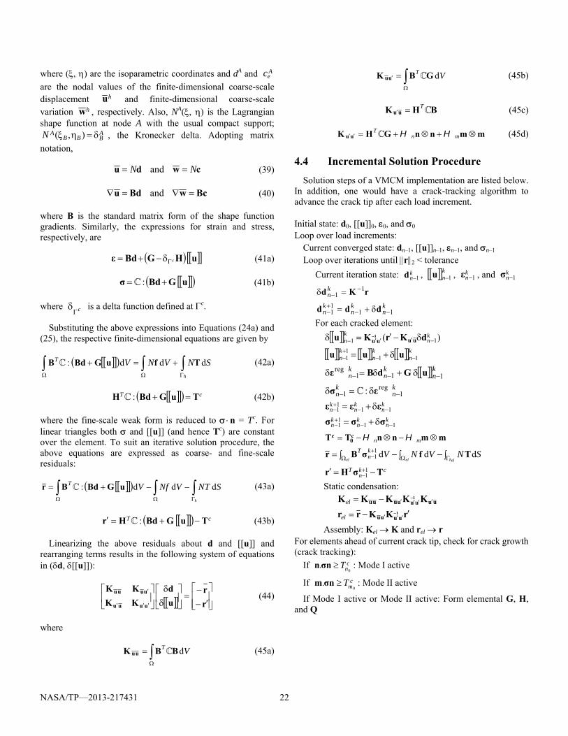
NASA/TP—2013-217431 22
where (, ) are the isoparametric coordinates and dA and Aec
are the nodal values of the finite-dimensional coarse-scale displacement hu and finite-dimensional coarse-scale variation hw , respectively. Also, NA(, ) is the Lagrangian shape function at node A with the usual compact support;
ABBB
AN ),( , the Kronecker delta. Adopting matrix
notation,
cwdu NN and (39)
BcwBdu and (40)
where B is the standard matrix form of the shape function gradients. Similarly, the expressions for strain and stress, respectively, are
uHGBdε c (41a)
uGBdσ : (41b)
where c is a delta function defined at c.
Substituting the above expressions into Equations (24a) and (25), the respective finite-dimensional equations are given by
h
SNVNVT ddd: TfuGBdB (42a)
cT TuGBdH : (42b)
where the fine-scale weak form is reduced to n = Tc. For linear triangles both and [[u]] (and hence Tc) are constant over the element. To suit an iterative solution procedure, the above equations are expressed as coarse- and fine-scale residuals:
h
STNVfNVT ddd: uGBdBr (43a)
cT TuGBdHr : (43b)
Linearizing the above residuals about d and [[u]] and rearranging terms results in the following system of equations in (d, [[u]]):
r
ru
d
KK
KK
uuuu
uuuu (44)
where
VT dBBK uu (45a)
VT dGBK uu (45b)
BHK uu T (45c)
mmnnGHK uu mnT HH (45d)
4.4 Incremental Solution Procedure
Solution steps of a VMCM implementation are listed below. In addition, one would have a crack-tracking algorithm to advance the crack tip after each load increment.
Initial state: d0, [[u]]0, 0, and 0 Loop over load increments:
Current converged state: dn–1, [[u]]n–1, n–1, and n–1 Loop over iterations until r2 < tolerance
Current iteration state: kn 1d , kn 1u , k
n 1ε , and kn 1σ
rKd 11
k
n
kn
kn
kn 11
11 ddd
For each cracked element:
)( 11kn
kn dKrKu uuuu
1
knkn
kn 11
11 uuu
knkn
kn 111
reg uGdBε
kn
kn 1
reg1 : εσ
kn
kn
kn 11
11 εεε
kn
kn
kn 11
11 σσσ
mmnnTT c0
c mn HH
SNVNVelhelel
kn
T ddd11 TfσBr
ckn
T TσHr 11
Static condensation:
uuuuuuuu KKKKK 1
el
rKKrr 1uuuu
el
Assembly: Kel K and rel r For elements ahead of current crack tip, check for crack growth(crack tracking):
If cnT
0. nσn : Mode I active
If cmT
0. nσm : Mode II active
If Mode I active or Mode II active: Form elemental G, H,and Q
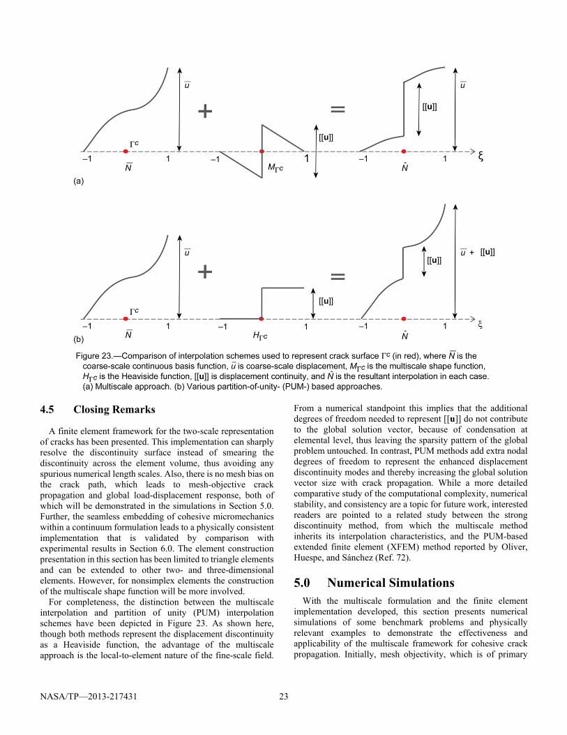
NASA/TP—2013-217431 23
4.5 Closing Remarks
A finite element framework for the two-scale representation of cracks has been presented. This implementation can sharply resolve the discontinuity surface instead of smearing the discontinuity across the element volume, thus avoiding any spurious numerical length scales. Also, there is no mesh bias on the crack path, which leads to mesh-objective crack propagation and global load-displacement response, both of which will be demonstrated in the simulations in Section 5.0. Further, the seamless embedding of cohesive micromechanics within a continuum formulation leads to a physically consistent implementation that is validated by comparison with experimental results in Section 6.0. The element construction presentation in this section has been limited to triangle elements and can be extended to other two- and three-dimensional elements. However, for nonsimplex elements the construction of the multiscale shape function will be more involved.
For completeness, the distinction between the multiscale interpolation and partition of unity (PUM) interpolation schemes have been depicted in Figure 23. As shown here, though both methods represent the displacement discontinuity as a Heaviside function, the advantage of the multiscale approach is the local-to-element nature of the fine-scale field.
From a numerical standpoint this implies that the additional degrees of freedom needed to represent [[u]] do not contribute to the global solution vector, because of condensation at elemental level, thus leaving the sparsity pattern of the global problem untouched. In contrast, PUM methods add extra nodal degrees of freedom to represent the enhanced displacement discontinuity modes and thereby increasing the global solution vector size with crack propagation. While a more detailed comparative study of the computational complexity, numerical stability, and consistency are a topic for future work, interested readers are pointed to a related study between the strong discontinuity method, from which the multiscale method inherits its interpolation characteristics, and the PUM-based extended finite element (XFEM) method reported by Oliver, Huespe, and Sánchez (Ref. 72).
5.0 Numerical Simulations With the multiscale formulation and the finite element
implementation developed, this section presents numerical simulations of some benchmark problems and physically relevant examples to demonstrate the effectiveness and applicability of the multiscale framework for cohesive crack propagation. Initially, mesh objectivity, which is of primary
NASA/TP—2013-217431 24
importance in finite-element-based crack propagation simulations, is presented in Section 5.1. Then mixed-mode crack propagation in some benchmark problems is discussed in Section 5.2. Later, more complex scenarios of multiple and interacting crack are addressed in Section 5.3, and finally, closing remarks are provided in Section 5.4.
All simulations are in two dimensions and assume plane stress conditions. Also, in all simulations the crack evolves from a preexisting “starter crack.” Further, as indicated in Section 4.4, a crack tracking algorithm is required as part of the iterative process to evolve the crack from one element to another. Such an algorithm should be based on a physically relevant crack direction criterion and may be material and microstructure subjective. In this work, it is assumed that the crack propagates along a path that renders the shear stress to be zero. This amounts to assuming that the crack is locally governed by a Mode I criterion. However, the direction criterion places no limitation on the multiscale formulation, and depending on the material micromechanics, any relevant direction criterion can be chosen.
It is also pointed out that apparent distortion of the elements may be seen as contradicting the infinitesimal-strain assumption of linear elasticity and also potentially results in singular Jacobians for those elements. This is not the case:
(1) Only the regular component of the strain needs to satisfy the infinitesimal-strain assumption, as the singular component that lead to this observed element distortion does not contribute to the stress-strain constitutive relation (Sec. 3.3).
(2) Since the implementation is in the reference configuration, the element distortion has no effect on the parametric space to real space mapping.
To remove this potential confusion, the crack path elements are removed from the simulation plots during postprocessing, except in Section 5.1 where the discussion is primarily based on the mesh.
All the simulations were carried out using an in-house VMCM finite element code based on C++ developed by the author. A standard Newton-Raphson scheme was used for solving the system of nonlinear equations, based on a direct solution procedure using the SuperLU library (Ref. 73).
5.1 Mesh Objectivity Demonstration
The discussion in Section 4.1 highlights the mesh sensitivity of the standard finite element implementation for simulating crack propagation. As stated previously, eliminating pathological mesh dependence of crack propagation simulations is one of the primary motivations for the development of the multiscale framework, and this section seeks to demonstrate the mesh objectivity of this implementation. The results presented in this section focus on the dependence of the global load-displacement response and the crack path, the two most important metrics from a structural viewpoint, on the mesh density.
5.1.1 Straight Crack Propagation
Consider the problem of a cohesive tension block under uniaxial tension, as shown in Figure 24. Shown are the problem schematic, resulting crack paths for meshes whose density varies over two orders of magnitude, and the corresponding global load-displacement response. It should be sufficiently clear from this result that the traditional pathological mesh dependence is completely absent for the case of a straight crack path. However, this physical problem involves no crack turning, so the sensitivity of the crack path discussed in Section 4.1.2 is not manifested here. A more complex problem involving curved crack propagation is presented in the following subsection.
The load-displacement response in Figure 24(c) is physically relevant, as it indicates that the strain energy release rate G and the surface energy density (Sec. 2.1.1.1) are mesh independent, because the area under the curve is equal to the energy dissipated because of surface creation.
5.1.2 Curved Crack Propagation
Figure 25 shows the response of a standard single edge notch three-point bend (SETB) specimen under eccentric loading conditions. Because of the unsymmetrical loading, the crack deviates from its straight path and approaches the loading point as this is the contour of the maximum normal tractions, and the load-displacement and crack path is objectively simulated across all the mesh densities considered.
However, at first glance, the small variation in the load-displacement response and crack path may suggest mesh sensitivity. This is expected, as even in the absence of cracks, the resolution of the high stress gradients does depend to a small degree on the element dimension, and this naturally affects the crack direction determination and consequently the load-displacement response. Thus, these small variations are not pathological, as can be seen from Figure 25(c), but an artifact associated with numerical discretization used in the finite element method.
5.2 Mixed-Mode Crack Propagation
“Mixed mode” refers to the condition where the crack face is subjected to both in-plane and out-of-plane tractions. In two dimensions this means that the crack face is under the influence of both Mode I opening tractions and Mode II shear tractions. Crack propagation involving nonstraight paths is often mixed mode, and so there will be two cohesive traction-separation relations corresponding to normal-opening and shear-slipping modes. This section demonstrates the mixed-mode fracture simulation capability of the multiscale implementation. As stated earlier, the crack path elements are removed, and for better visualization only the field contours are shown, without the underlying mesh.
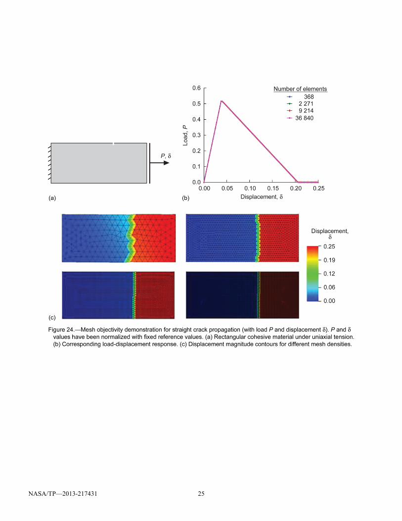
NASA/TP—2013-217431 25
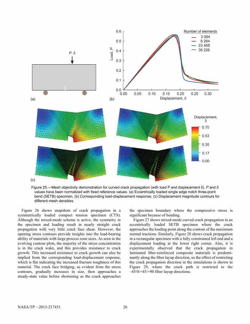
NASA/TP—2013-217431 26
Figure 26 shows snapshots of crack propagation in a symmetrically loaded compact tension specimen (CTS). Although the mixed-mode scheme is active, the symmetry in the specimen and loading result in nearly straight crack propagation with very little crack face shear. However, the opening stress contours provide insights into the load-bearing ability of materials with large process zone sizes. As seen in the evolving contour plots, the majority of the stress concentration is in the crack wake, and this provides resistance to crack growth. This increased resistance to crack growth can also be implied from the corresponding load-displacement response, which is flat indicating the increased fracture toughness of this material. The crack face bridging, as evident from the stress contours, gradually increases in size, then approaches a steady-state value before shortening as the crack approaches
the specimen boundary where the compressive stress is significant because of bending.
Figure 27 shows mixed-mode curved crack propagation in an eccentrically loaded SETB specimen where the crack approaches the loading point along the contour of the maximum normal tractions. Similarly, Figure 28 shows crack propagation in a rectangular specimen with a fully constrained left end and a displacement loading at the lower right corner. Also, it is experimentally observed that the crack propagation in laminated fiber-reinforced composite materials is predomi-nantly along the fiber layup direction, so the effect of restricting the crack propagation direction in the simulations is shown in Figure 29, where the crack path is restricted to the –45/0/+45/+90 fiber layup directions.
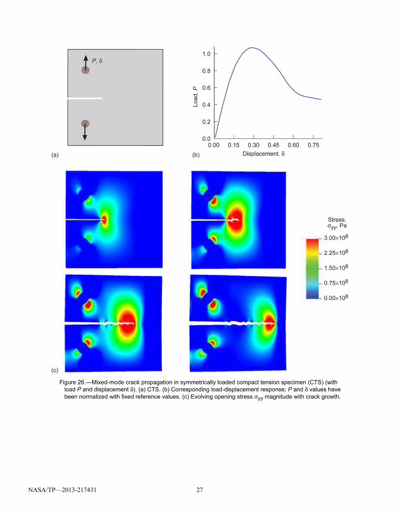
NASA/TP—2013-217431 27
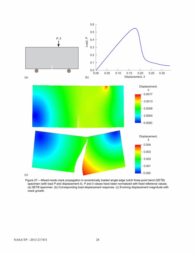
NASA/TP—2013-217431 28
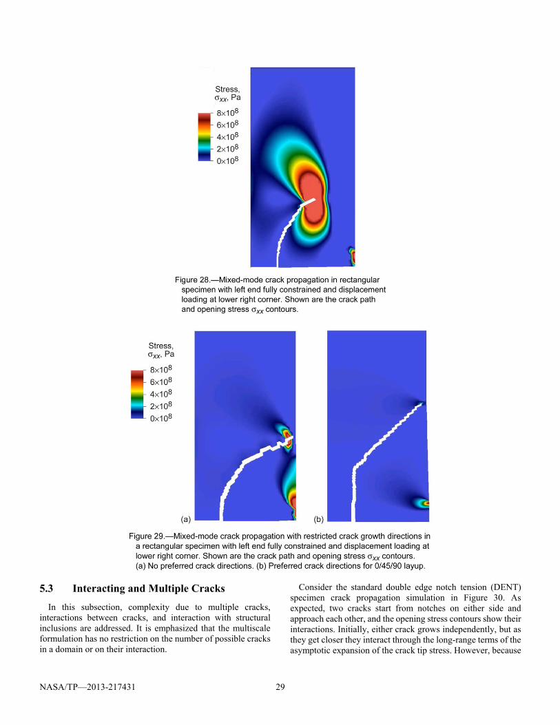
NASA/TP—2013-217431 29
5.3 Interacting and Multiple Cracks
In this subsection, complexity due to multiple cracks, interactions between cracks, and interaction with structural inclusions are addressed. It is emphasized that the multiscale formulation has no restriction on the number of possible cracks in a domain or on their interaction.
Consider the standard double edge notch tension (DENT) specimen crack propagation simulation in Figure 30. As expected, two cracks start from notches on either side and approach each other, and the opening stress contours show their interactions. Initially, either crack grows independently, but as they get closer they interact through the long-range terms of the asymptotic expansion of the crack tip stress. However, because
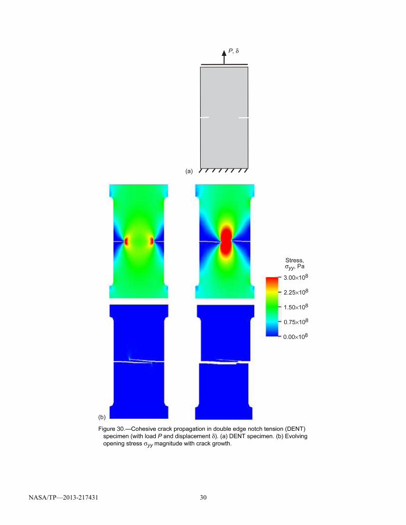
NASA/TP—2013-217431 30
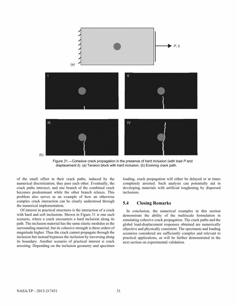
NASA/TP—2013-217431 31
of the small offset in their crack paths, induced by the numerical discretization, they pass each other. Eventually, the crack paths intersect, and one branch of the combined crack becomes predominant while the other branch relaxes. This problem also serves as an example of how an otherwise complex crack interaction can be clearly understood through the numerical implementation.
Of interest in practical structures is the interaction of a crack with hard and soft inclusions. Shown in Figure 31 is one such scenario, where a crack encounters a hard inclusion along its path. The inclusion material has the same elastic modulus as the surrounding material, but its cohesive strength is three orders of magnitude higher. Thus the crack cannot propagate through the inclusion but instead bypasses the inclusion by traversing along its boundary. Another scenario of practical interest is crack arresting. Depending on the inclusion geometry and specimen
loading, crack propagation will either be delayed or at times completely arrested. Such analysis can potentially aid in developing materials with artificial toughening by dispersed inclusions.
5.4 Closing Remarks
In conclusion, the numerical examples in this section demonstrate the ability of the multiscale formulation in simulating cohesive crack propagation. The crack paths and the global load-displacement responses obtained are numerically objective and physically consistent. The specimens and loading scenarios considered are sufficiently complex and relevant to practical applications, as will be further demonstrated in the next section on experimental validation.
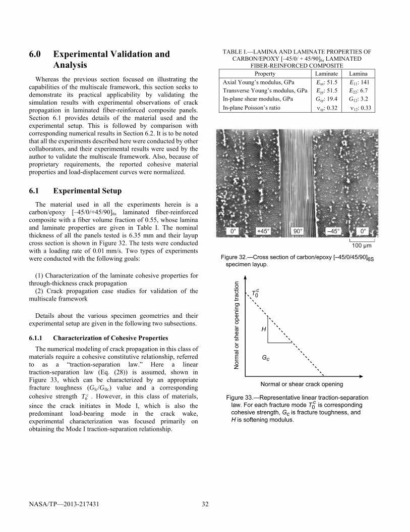
NASA/TP—2013-217431 32
6.0 Experimental Validation and Analysis
Whereas the previous section focused on illustrating the capabilities of the multiscale framework, this section seeks to demonstrate its practical applicability by validating the simulation results with experimental observations of crack propagation in laminated fiber-reinforced composite panels. Section 6.1 provides details of the material used and the experimental setup. This is followed by comparison with corresponding numerical results in Section 6.2. It is to be noted that all the experiments described here were conducted by other collaborators, and their experimental results were used by the author to validate the multiscale framework. Also, because of proprietary requirements, the reported cohesive material properties and load-displacement curves were normalized.
6.1 Experimental Setup
The material used in all the experiments herein is a carbon/epoxy [–45/0/+45/90]6s laminated fiber-reinforced composite with a fiber volume fraction of 0.55, whose lamina and laminate properties are given in Table I. The nominal thickness of all the panels tested is 6.35 mm and their layup cross section is shown in Figure 32. The tests were conducted with a loading rate of 0.01 mm/s. Two types of experiments were conducted with the following goals:
(1) Characterization of the laminate cohesive properties for through-thickness crack propagation
(2) Crack propagation case studies for validation of the multiscale framework
Details about the various specimen geometries and their experimental setup are given in the following two subsections.
6.1.1 Characterization of Cohesive Properties
The numerical modeling of crack propagation in this class of materials require a cohesive constitutive relationship, referred to as a “traction-separation law.” Here a linear traction-separation law (Eq. (28)) is assumed, shown in Figure 33, which can be characterized by an appropriate fracture toughness (GIc/GIIc) value and a corresponding cohesive strength cT0 . However, in this class of materials,
since the crack initiates in Mode I, which is also the predominant load-bearing mode in the crack wake, experimental characterization was focused primarily on obtaining the Mode I traction-separation relationship.
TABLE I.—LAMINA AND LAMINATE PROPERTIES OF CARBON/EPOXY [–45/0/ + 45/90]6s LAMINATED
FIBER-REINFORCED COMPOSITE Property Laminate Lamina
Axial Young’s modulus, GPa Exx: 51.5 E11: 141 Transverse Young’s modulus, GPa Eyy: 51.5 E22: 6.7 In-plane shear modulus, GPa Gxy: 19.4 G12: 3.2
In-plane Poisson’s ratio xy: 0.32 12: 0.33
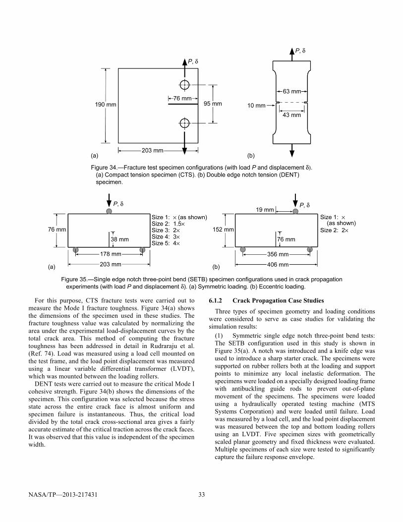
NASA/TP—2013-217431 33
For this purpose, CTS fracture tests were carried out to measure the Mode I fracture toughness. Figure 34(a) shows the dimensions of the specimen used in these studies. The fracture toughness value was calculated by normalizing the area under the experimental load-displacement curves by the total crack area. This method of computing the fracture toughness has been addressed in detail in Rudraraju et al. (Ref. 74). Load was measured using a load cell mounted on the test frame, and the load point displacement was measured using a linear variable differential transformer (LVDT), which was mounted between the loading rollers.
DENT tests were carried out to measure the critical Mode I cohesive strength. Figure 34(b) shows the dimensions of the specimen. This configuration was selected because the stress state across the entire crack face is almost uniform and specimen failure is instantaneous. Thus, the critical load divided by the total crack cross-sectional area gives a fairly accurate estimate of the critical traction across the crack faces. It was observed that this value is independent of the specimen width.
6.1.2 Crack Propagation Case Studies
Three types of specimen geometry and loading conditions were considered to serve as case studies for validating the simulation results:
(1) Symmetric single edge notch three-point bend tests: The SETB configuration used in this study is shown in Figure 35(a). A notch was introduced and a knife edge was used to introduce a sharp starter crack. The specimens were supported on rubber rollers both at the loading and support points to minimize any local inelastic deformation. The specimens were loaded on a specially designed loading frame with antibuckling guide rods to prevent out-of-plane movement of the specimens. The specimens were loaded using a hydraulically operated testing machine (MTS Systems Corporation) and were loaded until failure. Load was measured by a load cell, and the load point displacement was measured between the top and bottom loading rollers using an LVDT. Five specimen sizes with geometrically scaled planar geometry and fixed thickness were evaluated. Multiple specimens of each size were tested to significantly capture the failure response envelope.
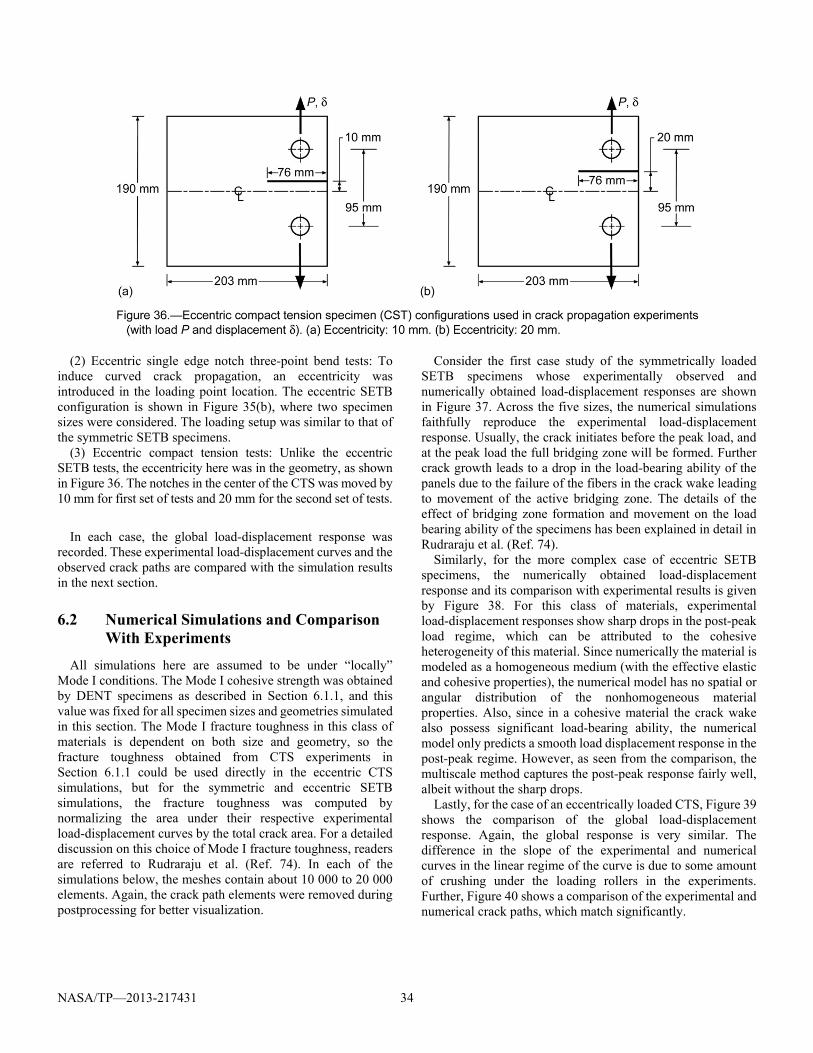
NASA/TP—2013-217431 34
(2) Eccentric single edge notch three-point bend tests: To induce curved crack propagation, an eccentricity was introduced in the loading point location. The eccentric SETB configuration is shown in Figure 35(b), where two specimen sizes were considered. The loading setup was similar to that of the symmetric SETB specimens.
(3) Eccentric compact tension tests: Unlike the eccentric SETB tests, the eccentricity here was in the geometry, as shown in Figure 36. The notches in the center of the CTS was moved by 10 mm for first set of tests and 20 mm for the second set of tests.
In each case, the global load-displacement response was
recorded. These experimental load-displacement curves and the observed crack paths are compared with the simulation results in the next section.
6.2 Numerical Simulations and Comparison With Experiments
All simulations here are assumed to be under “locally” Mode I conditions. The Mode I cohesive strength was obtained by DENT specimens as described in Section 6.1.1, and this value was fixed for all specimen sizes and geometries simulated in this section. The Mode I fracture toughness in this class of materials is dependent on both size and geometry, so the fracture toughness obtained from CTS experiments in Section 6.1.1 could be used directly in the eccentric CTS simulations, but for the symmetric and eccentric SETB simulations, the fracture toughness was computed by normalizing the area under their respective experimental load-displacement curves by the total crack area. For a detailed discussion on this choice of Mode I fracture toughness, readers are referred to Rudraraju et al. (Ref. 74). In each of the simulations below, the meshes contain about 10 000 to 20 000 elements. Again, the crack path elements were removed during postprocessing for better visualization.
Consider the first case study of the symmetrically loaded SETB specimens whose experimentally observed and numerically obtained load-displacement responses are shown in Figure 37. Across the five sizes, the numerical simulations faithfully reproduce the experimental load-displacement response. Usually, the crack initiates before the peak load, and at the peak load the full bridging zone will be formed. Further crack growth leads to a drop in the load-bearing ability of the panels due to the failure of the fibers in the crack wake leading to movement of the active bridging zone. The details of the effect of bridging zone formation and movement on the load bearing ability of the specimens has been explained in detail in Rudraraju et al. (Ref. 74).
Similarly, for the more complex case of eccentric SETB specimens, the numerically obtained load-displacement response and its comparison with experimental results is given by Figure 38. For this class of materials, experimental load-displacement responses show sharp drops in the post-peak load regime, which can be attributed to the cohesive heterogeneity of this material. Since numerically the material is modeled as a homogeneous medium (with the effective elastic and cohesive properties), the numerical model has no spatial or angular distribution of the nonhomogeneous material properties. Also, since in a cohesive material the crack wake also possess significant load-bearing ability, the numerical model only predicts a smooth load displacement response in the post-peak regime. However, as seen from the comparison, the multiscale method captures the post-peak response fairly well, albeit without the sharp drops.
Lastly, for the case of an eccentrically loaded CTS, Figure 39 shows the comparison of the global load-displacement response. Again, the global response is very similar. The difference in the slope of the experimental and numerical curves in the linear regime of the curve is due to some amount of crushing under the loading rollers in the experiments. Further, Figure 40 shows a comparison of the experimental and numerical crack paths, which match significantly.
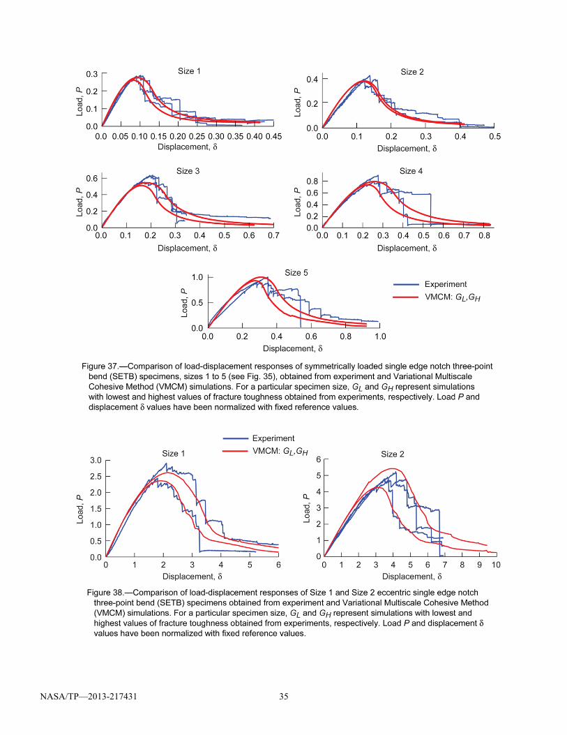
NASA/TP—2013-217431 35
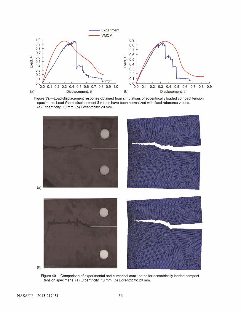
NASA/TP—2013-217431 36
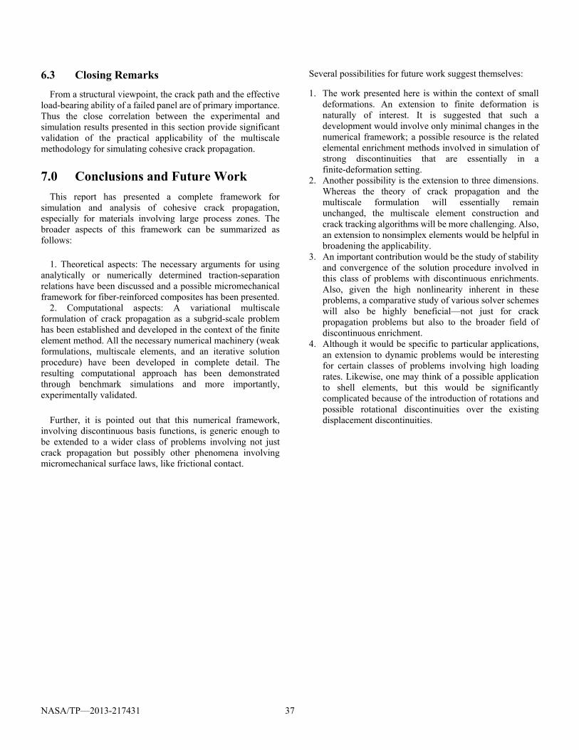
NASA/TP—2013-217431 37
6.3 Closing Remarks
From a structural viewpoint, the crack path and the effective load-bearing ability of a failed panel are of primary importance. Thus the close correlation between the experimental and simulation results presented in this section provide significant validation of the practical applicability of the multiscale methodology for simulating cohesive crack propagation.
7.0 Conclusions and Future Work
This report has presented a complete framework for simulation and analysis of cohesive crack propagation, especially for materials involving large process zones. The broader aspects of this framework can be summarized as follows:
1. Theoretical aspects: The necessary arguments for using
analytically or numerically determined traction-separation relations have been discussed and a possible micromechanical framework for fiber-reinforced composites has been presented.
2. Computational aspects: A variational multiscale formulation of crack propagation as a subgrid-scale problem has been established and developed in the context of the finite element method. All the necessary numerical machinery (weak formulations, multiscale elements, and an iterative solution procedure) have been developed in complete detail. The resulting computational approach has been demonstrated through benchmark simulations and more importantly, experimentally validated.
Further, it is pointed out that this numerical framework,
involving discontinuous basis functions, is generic enough to be extended to a wider class of problems involving not just crack propagation but possibly other phenomena involving micromechanical surface laws, like frictional contact.
Several possibilities for future work suggest themselves:
1. The work presented here is within the context of small deformations. An extension to finite deformation is naturally of interest. It is suggested that such a development would involve only minimal changes in the numerical framework; a possible resource is the related elemental enrichment methods involved in simulation of strong discontinuities that are essentially in a finite-deformation setting.
2. Another possibility is the extension to three dimensions. Whereas the theory of crack propagation and the multiscale formulation will essentially remain unchanged, the multiscale element construction and crack tracking algorithms will be more challenging. Also, an extension to nonsimplex elements would be helpful in broadening the applicability.
3. An important contribution would be the study of stability and convergence of the solution procedure involved in this class of problems with discontinuous enrichments. Also, given the high nonlinearity inherent in these problems, a comparative study of various solver schemes will also be highly beneficial—not just for crack propagation problems but also to the broader field of discontinuous enrichment.
4. Although it would be specific to particular applications, an extension to dynamic problems would be interesting for certain classes of problems involving high loading rates. Likewise, one may think of a possible application to shell elements, but this would be significantly complicated because of the introduction of rotations and possible rotational discontinuities over the existing displacement discontinuities.

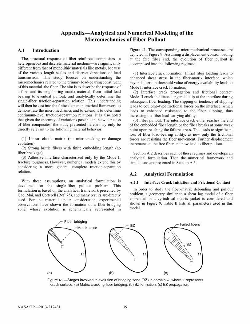
NASA/TP—2013-217431 39
Appendix—Analytical and Numerical Modeling of the Micromechanics of Fiber Pullout
A.1 Introduction
The structural response of fiber-reinforced composites—a heterogeneous and discrete material medium—are significantly different from that of monolithic materials like metals, because of the various length scales and discreet directions of load transmission. This study focuses on understanding the micromechanics related to the primary load-bearing constituent of this material, the fiber. The aim is to describe the response of a fiber and its neighboring matrix material, from initial load bearing to eventual pullout, and analytically determine the single-fiber traction-separation relation. This understanding will then be cast into the finite element numerical framework to demonstrate the micromechanics and to extend it to determine continuum-level traction-separation relations. It is also noted that given the enormity of variations possible in the wider class of fiber composites, the study presented herein may only be directly relevant to the following material behavior:
(1) Linear elastic matrix (no microcracking or damage
evolution) (2) Strong brittle fibers with finite embedding length (no
fiber breakage) (3) Adhesive interface characterized only by the Mode II
fracture toughness. However, numerical models extend this by considering a more general complete traction-separation relation.
With these assumptions, an analytical formulation is
developed for the single-fiber pullout problem. This formulation is based on the analytical framework presented by Gao, Mai, and Cotterell (Ref. 75), and many results are directly used. For the material under consideration, experimental observations have shown the formation of a fiber-bridging zone, whose evolution is schematically represented in
Figure 41. The corresponding micromechanical processes are depicted in Figure 9. Assuming a displacement-control loading at the free fiber end, the evolution of fiber pullout is decomposed into the following regimes:
(1) Interface crack formation: Initial fiber loading leads to
enhanced shear stress in the fiber-matrix interface, which beyond a certain threshold value of energy availability leads to Mode II interface crack formation.
(2) Interface crack propagation and frictional contact: Mode II crack facilitates tangential slip at the interface during subsequent fiber loading. The slipping or tendency of slipping leads to coulomb-type frictional forces on the interface, which leads to enhanced resistance to the fiber slipping, thus increasing the fiber load-carrying ability.
(3) Fiber pullout: The interface crack either reaches the end of the embedded fiber length or the fiber breaks at some weak point upon reaching the failure stress. This leads to significant loss of fiber load-bearing ability, as now only the frictional forces are resisting the fiber movement. Further displacement increments at the free fiber end now lead to fiber pullout.
Section A.2 describes each of these regimes and develops an
analytical formulation. Then the numerical framework and simulations are presented in Section A.3.
A.2 Analytical Formulation
A.2.1 Interface Crack Initiation and Frictional Contact
In order to study the fiber-matrix debonding and pullout problem, a geometry similar to a shear lag model of a fiber embedded in a cylindrical matrix jacket is considered and shown in Figure 9. Table II lists all parameters used in this model.
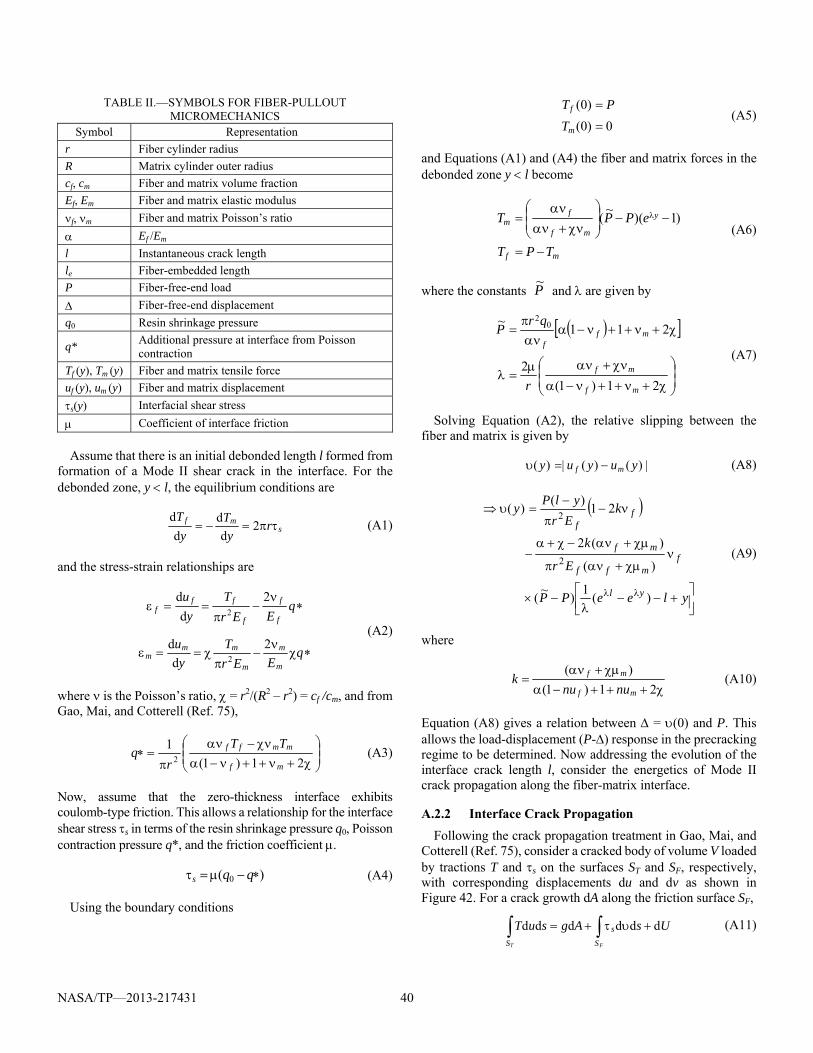
NASA/TP—2013-217431 40
TABLE II.—SYMBOLS FOR FIBER-PULLOUT MICROMECHANICS
Symbol Representation
r Fiber cylinder radius
R Matrix cylinder outer radius
cf, cm Fiber and matrix volume fraction
Ef, Em Fiber and matrix elastic modulus
f, m Fiber and matrix Poisson’s ratio
Ef /Em
l Instantaneous crack length
le Fiber-embedded length
P Fiber-free-end load
Fiber-free-end displacement
q0 Resin shrinkage pressure
q* Additional pressure at interface from Poisson contraction
Tf (y), Tm (y) Fiber and matrix tensile force
uf (y), um (y) Fiber and matrix displacement
s(y) Interfacial shear stress
Coefficient of interface friction
Assume that there is an initial debonded length l formed from
formation of a Mode II shear crack in the interface. For the debonded zone, y l, the equilibrium conditions are
smf ry
Ty
T 2
d
d
d
d (A1)
and the stress-strain relationships are
qEEr
Ty
u
qEEr
Ty
u
m
m
m
mmm
f
f
f
fff
2
d
d
2
d
d
2
2
(A2)
where is the Poisson’s ratio, = r2/(R2 – r2) = cf /cm, and from Gao, Mai, and Cotterell (Ref. 75),
21)1(
12
mf
mmff TTr
q (A3)
Now, assume that the zero-thickness interface exhibits coulomb-type friction. This allows a relationship for the interface shear stress s in terms of the resin shrinkage pressure q0, Poisson contraction pressure q*, and the friction coefficient .
)( 0 qqs (A4)
Using the boundary conditions
0)0(
)0(
m
f
TPT
(A5)
and Equations (A1) and (A4) the fiber and matrix forces in the debonded zone y l become
mf
y
mf
fm
TPT
ePPT
)1)(~
( (A6)
where the constants P~ and are given by
21)1(
2
211~ 0
2
mf
mf
mff
r
qrP
(A7)
Solving Equation (A2), the relative slipping between the fiber and matrix is given by
|)()(|)( yuyuy mf (A8)
yleePP
Er
k
kEr
ylPy
yl
fmff
mf
ff
)(1
)~
(
)(
)(2
21)(
)(
2
2
(A9)
where
21)1(
)(
mf
mf
nunuk (A10)
Equation (A8) gives a relation between = (0) and P. This allows the load-displacement (P-) response in the precracking regime to be determined. Now addressing the evolution of the interface crack length l, consider the energetics of Mode II crack propagation along the fiber-matrix interface.
A.2.2 Interface Crack Propagation
Following the crack propagation treatment in Gao, Mai, and Cotterell (Ref. 75), consider a cracked body of volume V loaded by tractions T and s on the surfaces ST and SF, respectively, with corresponding displacements du and dv as shown in Figure 42. For a crack growth dA along the friction surface SF,
FT S
s
S
UsAgsuT dddddd (A11)
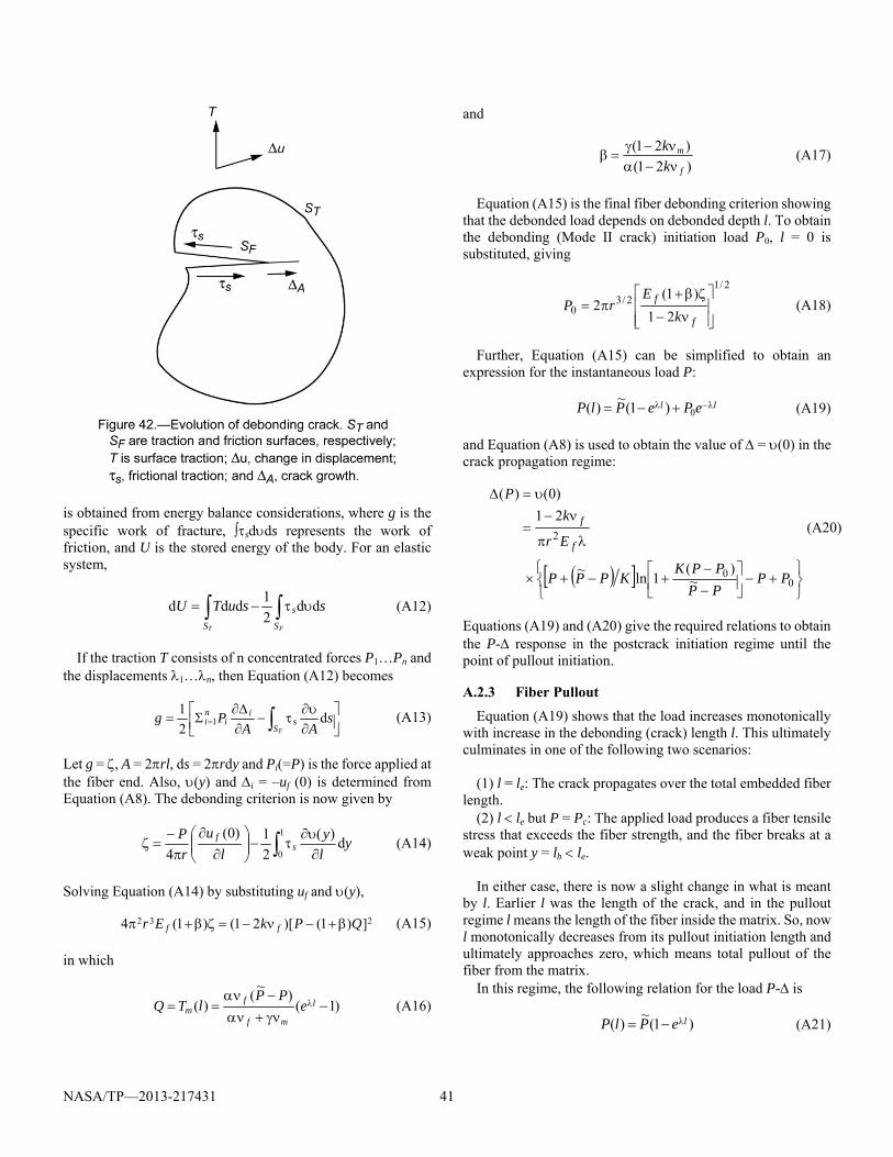
NASA/TP—2013-217431 41
is obtained from energy balance considerations, where g is the specific work of fracture, sdds represents the work of friction, and U is the stored energy of the body. For an elastic system,
FT S
s
S
ssuTU dd2
1ddd (A12)
If the traction T consists of n concentrated forces P1…Pn and the displacements 1…n, then Equation (A12) becomes
sAA
Pg sS
ii
ni
F
d2
11 (A13)
Let g = , A = 2rl, ds = 2rdy and Pi(=P) is the force applied at the fiber end. Also, (y) and i = –uf (0) is determined from Equation (A8). The debonding criterion is now given by
yly
lu
rP
sf d
)(
2
1)0(
4
1
0
(A14)
Solving Equation (A14) by substituting uf and (y),
232 ])1()[21()1(4 QPkEr ff (A15)
in which
)1()
~(
)(
l
mf
fm e
PPlTQ (A16)
and
)21(
)21(
f
m
kk
(A17)
Equation (A15) is the final fiber debonding criterion showing that the debonded load depends on debonded depth l. To obtain the debonding (Mode II crack) initiation load P0, l = 0 is substituted, giving
2/1
2/30 21
)1(2
f
f
kE
rP (A18)
Further, Equation (A15) can be simplified to obtain an expression for the instantaneous load P:
ll ePePlP 0)1(~
)( (A19)
and Equation (A8) is used to obtain the value of = (0) in the crack propagation regime:
00
2
~)(
1ln~
21
)0()(
PPPPPPK
KPPP
Er
kP
f
f(A20)
Equations (A19) and (A20) give the required relations to obtain the P- response in the postcrack initiation regime until the point of pullout initiation.
A.2.3 Fiber Pullout
Equation (A19) shows that the load increases monotonically with increase in the debonding (crack) length l. This ultimately culminates in one of the following two scenarios:
(1) l = le: The crack propagates over the total embedded fiber length.
(2) l le but P = Pc: The applied load produces a fiber tensile stress that exceeds the fiber strength, and the fiber breaks at a weak point y = lb le.
In either case, there is now a slight change in what is meant by l. Earlier l was the length of the crack, and in the pullout regime l means the length of the fiber inside the matrix. So, now l monotonically decreases from its pullout initiation length and ultimately approaches zero, which means total pullout of the fiber from the matrix.
In this regime, the following relation for the load P- is
)1(~
)( lePlP (A21)
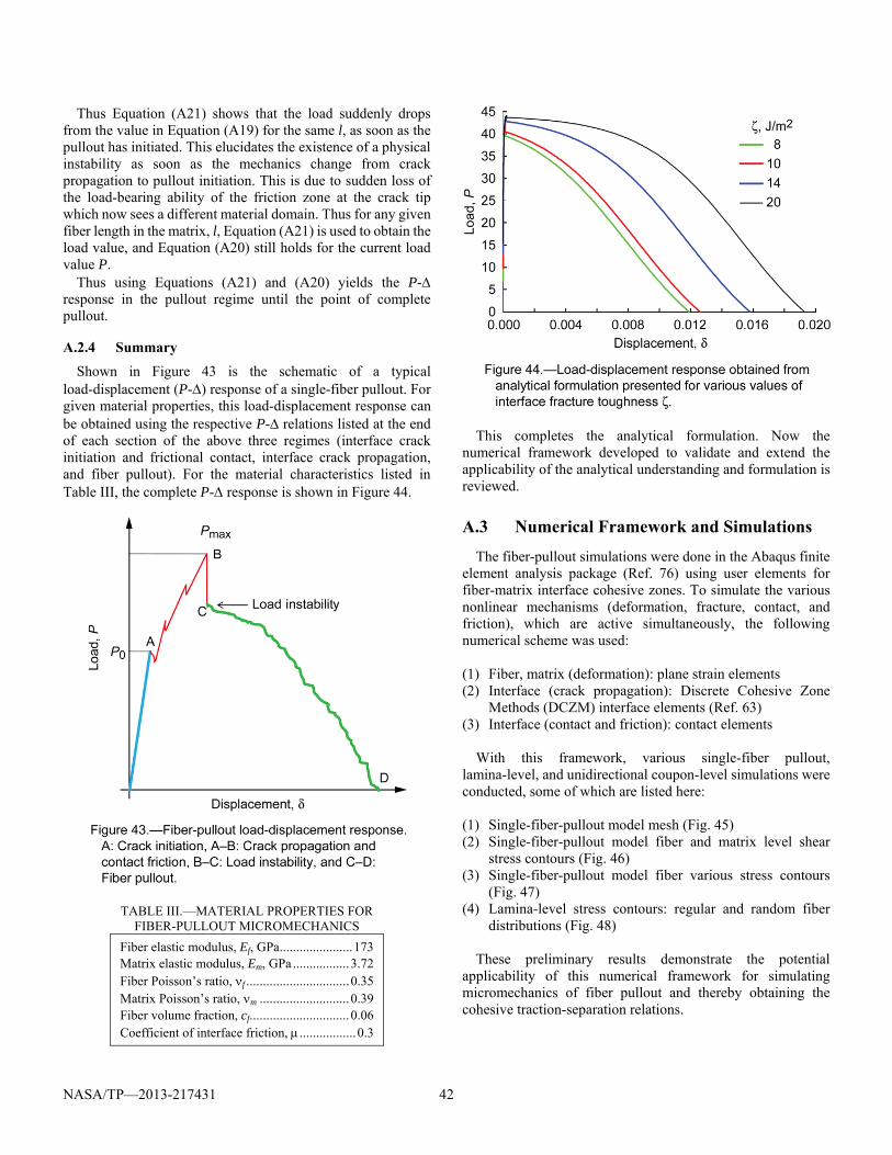
NASA/TP—2013-217431 42
Thus Equation (A21) shows that the load suddenly drops from the value in Equation (A19) for the same l, as soon as the pullout has initiated. This elucidates the existence of a physical instability as soon as the mechanics change from crack propagation to pullout initiation. This is due to sudden loss of the load-bearing ability of the friction zone at the crack tip which now sees a different material domain. Thus for any given fiber length in the matrix, l, Equation (A21) is used to obtain the load value, and Equation (A20) still holds for the current load value P.
Thus using Equations (A21) and (A20) yields the P- response in the pullout regime until the point of complete pullout.
A.2.4 Summary
Shown in Figure 43 is the schematic of a typical load-displacement (P-) response of a single-fiber pullout. For given material properties, this load-displacement response can be obtained using the respective P- relations listed at the end of each section of the above three regimes (interface crack initiation and frictional contact, interface crack propagation, and fiber pullout). For the material characteristics listed in Table III, the complete P- response is shown in Figure 44.
TABLE III.—MATERIAL PROPERTIES FOR FIBER-PULLOUT MICROMECHANICS
Fiber elastic modulus, Ef, GPa ...................... 173 Matrix elastic modulus, Em, GPa ................. 3.72 Fiber Poisson’s ratio, f ............................... 0.35 Matrix Poisson’s ratio, m ........................... 0.39 Fiber volume fraction, cf .............................. 0.06 Coefficient of interface friction, ................. 0.3
This completes the analytical formulation. Now the numerical framework developed to validate and extend the applicability of the analytical understanding and formulation is reviewed.
A.3 Numerical Framework and Simulations
The fiber-pullout simulations were done in the Abaqus finite element analysis package (Ref. 76) using user elements for fiber-matrix interface cohesive zones. To simulate the various nonlinear mechanisms (deformation, fracture, contact, and friction), which are active simultaneously, the following numerical scheme was used: (1) Fiber, matrix (deformation): plane strain elements (2) Interface (crack propagation): Discrete Cohesive Zone
Methods (DCZM) interface elements (Ref. 63) (3) Interface (contact and friction): contact elements
With this framework, various single-fiber pullout, lamina-level, and unidirectional coupon-level simulations were conducted, some of which are listed here:
(1) Single-fiber-pullout model mesh (Fig. 45) (2) Single-fiber-pullout model fiber and matrix level shear
stress contours (Fig. 46) (3) Single-fiber-pullout model fiber various stress contours
(Fig. 47) (4) Lamina-level stress contours: regular and random fiber
distributions (Fig. 48) These preliminary results demonstrate the potential
applicability of this numerical framework for simulating micromechanics of fiber pullout and thereby obtaining the cohesive traction-separation relations.
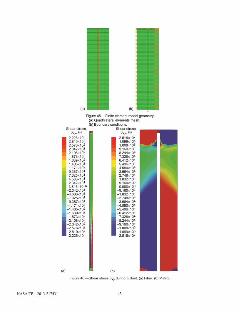
NASA/TP—2013-217431 43
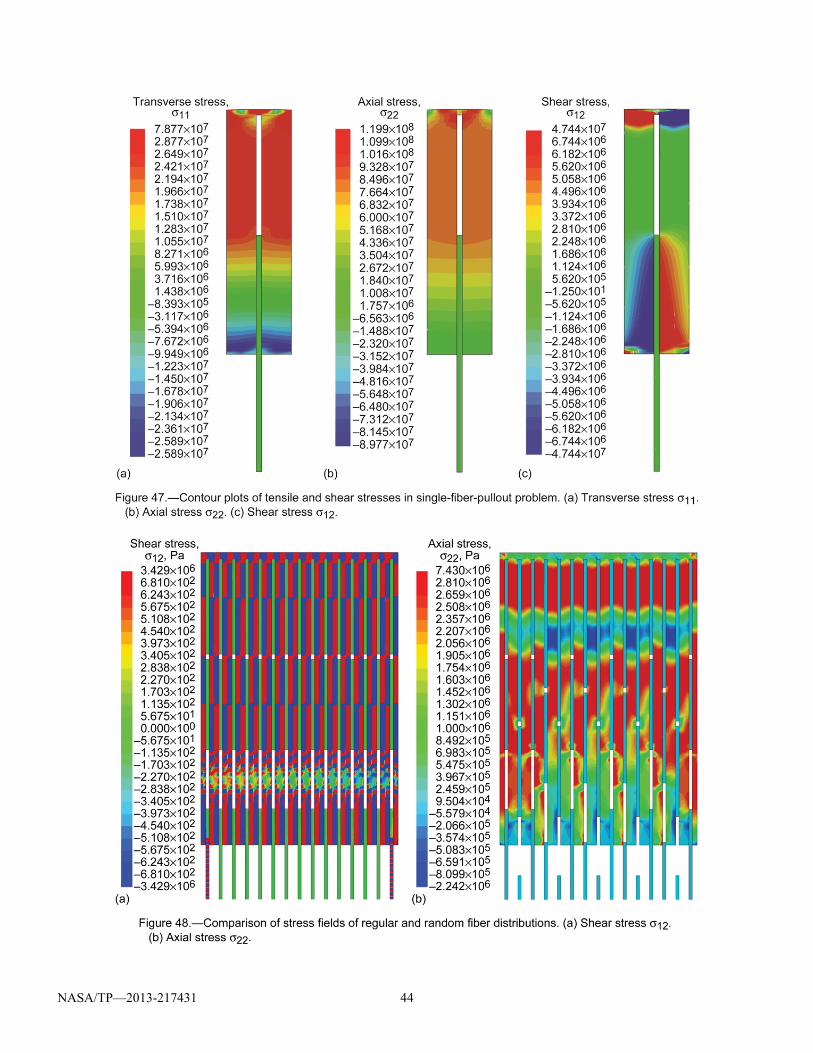
NASA/TP—2013-217431 44
NASA/TP—2013-217431 45
Glenn Research Center National Aeronautics and Space Administration Cleveland, Ohio, August 7, 2013.
References 1. Timoshenko, S.P.: Theory of Elasticity. McGraw-Hill, New
York, NY, 1934. 2. Truesdell, C.; and Noll, W.: The Non-Linear Field Theories of
Mechanics. Handbuch der Physik, S. Flugge, ed., Vol. 3, Springer-Verlag, Berlin, 1965.
3. Knowles, J.K.; and Sternberg, Eli: On a Class of Conservation Laws in Linearized and Finite Elastostatics. Arch. Ration. Mech. Anal., vol. 44, no. 3, 1972, pp. 187–211.
4. Marsden, Jerrold E.; and Hughes, Thomas J.R.: Mathematical Foundations of Elasticity. Dover Publications, New York, NY, 1994.
5. Barber, J.R.: Elasticity. Springer, Dordrecht, The Netherlands, 2010.
6. Hill, Rodney: The Mathematical Theory of Plasticity. Clarendon Press, Oxford, 1950.
7. Kachanov, L.M.: Foundations of the Theory of Plasticity. North-Holland Publishing Co., Amsterdam, 1971.
8. Lubliner, Jacob: Plasticity Theory. Collier Macmillan Publishing Co., New York, NY, 1990.
9. Simo, J.C.; and Hughes, T.J.R.: Computational Inelasticity. Springer-Verlag, New York, NY, 1998.
10. Kachanov, L.M.: Introduction to Continuum Damage Mechanics. Springer, Dordrecht, 1986.
11. Krajcinovic, Dusan: Damage Mechanics. Mech. Mater., vol. 8, nos. 2‒3, 1989, pp. 117–197.
12. Cooper, G.A.: The Fracture Toughness of Composites Reinforced With Weakened Fibres. J. Mater. Sci., vol. 5, no. 8, 1970, pp. 645–654.
13. Aveston, J.; Kelly, A.; and Cooper, G.A.: The Properties of Fibre Composites. Proceedings of the Properties of Fibre Composites Conference, Teddington, Middlesex, UK, 1971, pp. 24‒26.
14. Aveston, J.; and Kelly, A.: Theory of Multiple Fracture of Fibrous Composites. J. Mater. Sci., vol. 8, no. 3, 1973, pp. 352–362.
15. Cox, B.N.: Extrinsic Factors in the Mechanics of Bridged Cracks. Acta Metall. Mater., vol. 39, no. 6, 1991, pp. 1189–1201.
16. Griffith, A.A.: The Phenomena of Rupture and Flow in Solids. Philos. Trans. R. Soc. London, Ser. A, vol. 221, 1921, pp. 163–198.
17. Irwin, G.R.: Analysis of Stresses and Strains Near the End of a Crack Traversing a Plate. J. Appl. Mech., vol. 24, no. 3, 1957, pp. 361–364.
18. Barenblatt, G.I.: The Mathematical Theory of Equilibrium Cracks in Brittle Fracture. Adv. Appl. Mech., vol. 7, 1962, pp. 55–129.
19. Dugdale, D.S.: Yielding of Steel Sheets Containing Slits. J. Mech. Phys. Solids, vol. 8, 1960, pp. 100–104.
20. Cherepanov, G.P.: Crack Propagation in Continuous Media. J. Appl. Math. Mech., vol. 31, no. 3, 1967, pp. 476–488.
21. Rice, J.R.: A Path Independent Integral and the Approximate Analysis of Strain Concentration by Notches and Cracks. J. Appl. Mech., vol. 35, no. 2, 1968, pp. 379–386.
22. Pietruszczak, S.T.; and Mroz, Z.: Finite Element Analysis of Deformation of Strain-Softening Materials. Int. J. Numer. Methods Eng., vol. 17, 1981, pp. 327–334.
23. Ungsuwarungsri, T.; and Knauss, W.G.: The Role of Damage-Softened Material Behavior in the Fracture of
Composites and Adhesives. Int. J. Fract., vol. 35, no. 3, 1987, pp. 221–241.
24. Song, Seungjae; and Waas, Anthony M.: A Nonlinear Elastic Foundation Model for Interlaminar Fracture of Laminated Composites. Composites Engineering, vol. 3, no. 10, 1993, pp. 945–959.
25. Schellekens, J.C.J.; and DeBorst, R.: On the Numerical Integration of Interface Elements. Int. J. Numer. Methods Eng., vol. 36, 1993, pp. 43–66.
26. Xu, X.-P.; and Needleman, A.: Numerical Simulations of Fast Crack Growth in Brittle Solids. J. Mech. Phys. Solids, vol. 42, no. 9, 1994, pp. 1397–1434.
27. Camacho, G.T.; and Ortiz M.: Computational Modeling of Impact Damage in Brittle Materials. Int. J. Solids Struct., vol. 33, no. 20‒22, 1996, pp. 2899–2938.
28. Needleman, A.; and Tvergaard, V.: On the Finite Element Analysis of Localized Plastic Deformation. Finite Elements: Special Problems in Solid Mechanics, Prentice-Hall, Englewood Cliffs, NJ, 1984, pp. 94–157.
29. Bazant, Zdenek P.: Mechanics of Distributed Cracking. Appl. Mech. Rev., vol. 39, no. 5, 1986, pp. 675–705.
30. Crisfield, M.: Solution Strategies and Softening Materials. Comput. Meth. Appl. Mech. Eng., vol. 66, no. 3, 1988, pp. 267– 289.
31. Armero, F.; and Garikipati, K.: An Analysis of Strong Discontinuities in Multiplicative Finite Strain Plasticity and Their Relation With the Numerical Simulation of Strain Localization in Solids. Int. J. Solids Struct., vol. 33, no. 20‒22, 1996, pp. 2863–2885.
32. Larsson, Ragnar; Runesson, Kenneth; and Ottosen, Niels Saabye: Discontinuous Displacement Approximation for Capturing Plastic Localization. Int. J. Numer. Methods Eng., vol. 36, no. 12, 1993, pp. 2087‒2105.
33. Ramakrishnan, N.; Okada, H.; and Atluri, S.N.: On Shear Band Formation: II. Simulation Using Finite Element Method. Int. J. Plast., vol. 10, no. 5, 1994, pp. 521–534.
34. Moes, Nicolas; Dolbow, John; and Belytschko, Ted: A Finite Element Method for Crack Growth Without Remeshing. Int. J. Numer. Methods Eng., vol. 46, 1999, pp. 131–150.
35. Moes, Nicolas; and Belytschko, Ted: Extended Finite Element Method for Cohesive Crack Growth. Eng. Fract. Mech., vol. 69, 2002, pp. 813–833.
36. Dolbow, John; Moes, Nicolas; and Belytschko, Ted: An Extended Finite Element Method for Modeling Crack Growth With Frictional Contact. Comput. Meth. Appl. Mech. Eng., vol. 190, 2001, pp. 6825–6846.
37. Wells, G.N.; and Sluys, L.J.: A New Method for Modelling Cohesive Cracks Using Finite Elements. Int. J. Numer. Methods Eng., vol. 50, no. 12, 2001, pp. 2667–2682.
38. Hughes, Thomas J.R.: Multiscale Phenomena: Green’s Functions, the Dirichlet-to-Neumann Formulation, Subgrid Scale Models, Bubbles and the Origins of Stabilized Methods. Comput. Meth. Appl. Mech. Eng., vol. 127, nos. 1‒4, 1995, pp. 387–401.
39. Garikipati, Krishna; and. Hughes, Thomas J.R.: A Study of Strain Localization in a Multiple Scale Framework—The One-Dimensional Problem. Comput. Meth. Appl. Mech. Eng., vol. 159, 1998, pp. 193–222.
40. Garikipati, K.: A Variational Multiscale Method to Embed Micromechanical Surface Laws in the Macromechanical Continuum Formulation. CMES, vol. 3, no. 2, 2002, pp. 175–184.
NASA/TP—2013-217431 46
41. Raizer, Yurii P.: Physical Principles of the Theory of Brittle Fracture Cracks. Sov. Phys. Usp., vol. 13, no. 1, 1970.
42. Kolosov, G.: On One Application of the Theory of Functions of Complex Variables to the Plane Problem of the Mathematical Theory of Elasticity. Yur'ev (in Russian), 1909.
43. Inglis, C.E.: Stresses in a Plate Due To the Presence of Cracks and Sharp Corners. Presented at the Fifty-fourth Session of the Institution of Naval Architects, London, England, 1913, pp. 219–241.
44. Muschelov, N.J.: Sur l´intégration de l´Equation Biharmonique. Bulletin de l´Académie des Sciences de Russie. VI série, vol. 13, 1919, nos. 12‒15, pp. 663–686.
45. Williams, M.L.: Stress Singularities Resulting From Various Boundary Conditions in Angular Corners of Plates Under Bending. J. Appl. Mech., vol. 19, 1952, pp. 526‒528.
46. Barenblatt, Grigorij: Scaling, Self-Similarity, and Intermediate Asymptotics. Cambridge University Press, Cambridge, UK, 1996.
47. Willis, J.R.: A Comparison of the Fracture Criteria of Griffith and Barenblatt. J. Mech. Phys. Solids, vol. 15, no. 3, 1967, pp. 151–162.
48. Li, S., et al.: Use of a Cohesive-Zone Model to Analyze the Fracture of a Fiber-Reinforced Polymer-Matrix Composite. Compos. Sci. Technol., vol. 65, nos. 3 and 4, 2005, pp. 537–549.
49. Sun, C.T.; and Jin, Z.-H.: Modeling of Composite Fracture Using Cohesive Zone and Bridging Models. Compos. Sci. Technol., vol. 66, no. 10, 2006, pp. 1297–1302.
50. Hillerborg, A.; Modeer, M.; and Petersson, P.-E.: Analysis of Crack Formation and Crack Growth in Concrete by Means of Fracture Mechanics and Finite Elements. Cem. Concr. Res., vol. 6, no. 6, 1976, pp. 773–781.
51. Xie, De; and Biggers, Sherrill B., Jr.: Strain Energy Release Rate Calculation for a Moving Delamination Front of Arbitrary Shape Based on Virtual Crack Closure Technique. Part I: Formulation and Validation. Eng. Fract. Mech., vol. 73, 2006, pp. 771–785.
52. Hertzberg, Richard W.: Deformation and Fracture Mechanics of Engineering Materials. Wiley, New York, NY, 1983.
53. Xie, De; and Biggers, Sherrill B., Jr.: Strain Energy Release Rate Calculation for a Moving Delamination Front of Arbitrary Shape Based on Virtual Crack Closure Technique. Part II: Sensitivity Study on Modeling Details. Eng. Fract. Mech., vol. 73, 2006, pp. 786–801.
54. Xie, De, et al.: Computation of Energy Release Rates for Kinking Cracks Based on Virtual Crack Closure Technique. CMES, vol. 6, no. 6, 2004, pp. 515‒524.
55. Xie, De, et al.: Failure Analysis of Adhesively Bonded Structures: From Coupon Level Data To Structure Level Predictions and Verification. Int. J. Fract., vol. 134, nos. 3‒4, 2005, pp. 231–250.
56. Xie, De; and Waas, Anthony M.: Discrete Cohesive Zone Model for Mixed-Mode Fracture Using Finite Element Analysis. Eng. Fract. Mech., vol. 73, 2006, pp. 1783–1796.
57. Salvi, Amit G.; Waas, Anthony M.; and Caliskan, Ari: Energy Absorption and Damage Propagation in 2D Triaxially Braided Carbon Fiber Composites: Effects of In Situ Matrix Properties. J. Mater. Sci., vol. 43, 2008, pp. 5168–5184.
58. Xie, De, et al.: Discrete Cohesive Zone Model To Simulate Static Fracture in 2D Triaxially Braided Carbon Fiber Composites. J. Compos. Mater., vol. 40, no. 22, 2006, pp. 2025‒2046.
59. Bazant, Zdenek P.; and Oh, B.H.: Crack Band Theory for Fracture of Concrete. Mater. Struct., vol. 16, no. 93, 1983, pp. 155–177.
60. Pandolfi, A.; Krysl, P.; and Ortiz, M.: Finite Element Simulation of Ring Expansion and Fragmentation: The Capturing of Length and Time Scales Through Cohesive Models of Fracture. Int. J. Fract., vol. 95, nos. 1‒4, 1999, pp. 279–297.
61. Espinosa, Horacio D.; Zavattieri, Pablo D.; and Dwivedi, Sunil K.: A Finite Deformation Continuum/Discrete Model for the Description of Fragmentation and Damage in Brittle Materials. J. Mech. Phys. Solids, vol. 46, no. 10, 1998, pp. 1909–1942.
62. Jin, Z.-H.; and Sun, C.T.: Cohesive Zone Modeling of Interface Fracture in Elastic Bi-Materials. Eng. Fract. Mech., vol. 72, no. 12, 2005, pp. 1805–1817.
63. Gustafson, Peter A.; and Waas, Anthony M.: The Influence of Adhesive Constitutive Parameters in Cohesive Zone Finite Element Models of Adhesively Bonded Joints. Int. J. Solids Struct., vol. 46, 2009, pp. 2201–2215.
64. Hughes, Thomas J.R., et al.: The Variational Multiscale Method—A Paradigm for Computational Mechanics. Comput. Meth. Appl. Mech. Eng., vol. 166, nos. 1‒2, 1998, pp. 3–24.
65. Garikipati, K.; and Hughes, T.J.R.: A Variational Multiscale Approach To Strain Localization—Formulation for Multidimensional Problems. Comput. Meth. Appl. Mech. Eng., vol. 188, 2000, pp. 39–60.
66. Temam, R.; and Strang, G.: Functions of Bounded Deformation. Arch. Rat. Mech. Anal., vol. 75, 1980, pp. 7–21.
67. Simo, J.C.; Oliver, J.; and Armero F.: An Analysis of Strong Discontinuities Induced by Strain-Softening in Rate-Independent Inelastic Solids. Computational Mechanics, vol. 12, no. 5, 1993, pp. 277–296.
68. Simo, J.C.; and Oliver, J.: A New Approach to the Analysis and Simulation of Strain Softening in Solids. Fracture and Damage in Quasibrittle Structures, E & FN Spon, London, 1994.
69. Suquet, P.M.: Sur les Equations de la Plasticite: Existence et Regularite des Solutions. J. de Mecanique, vol. 21, 1981, pp. 3–39.
70. Garikipati, Krishnakumar R.: On Strong Discontinuities in Inelastic Solids and Their Numerical Simulation. Ph.D. Thesis, Stanford University, 1996.
71. Bazant, Z.P.; and Cedolin, Luigi: Stability of Structures: Elastic, Inelastic, Fracture, and Damage Theories. Dover Publications, Mineola, NY, 2003.
72. Oliver, J.; Huespe, A.E.; and Sanchez, P.J.: A Comparative Study on Finite Elements for Capturing Strong Discontinuities: E‒FEM vs X‒FEM. Comput. Meth. Appl. Mech. Eng., vol. 195, nos. 37‒40, 2006, pp. 4732–4752.
73. Demmel, J.W., et al.: A Supernodal Approach to Sparse Partial Pivoting. SIAM J. Matrix Anal. Appl., vol. 20, no. 3, 1999, pp. 720–755.
74. Rudraraju, S.S., et al.: In-plane Fracture of Laminated Fiber Reinforced Composites With Varying Fracture Resistance: Experimental Observations and Numerical Crack Propagation Simulations. Int. J. Solids Struct., vol. 47, nos. 7‒8, 2010, pp. 901–911.
75. Gao, Yo-Chen; Mai, Yiu-Wing; and Cotterell, Brian: Fracture of Fiber-Reinforced Materials. ZAMP, vol. 39, no. 4, 1988, pp. 550–572.
76. Dassault Systèmes: Abaqus Unified FEA. Vélizy-Villacoublay Cedex, France. http://www.3ds.com/products/simulia/portfolio/abaqus/overview/ Accessed Nov. 26, 2012.

REPORT DOCUMENTATION PAGE Form Approved OMB No. 0704-0188
The public reporting burden for this collection of information is estimated to average 1 hour per response, including the time for reviewing instructions, searching existing data sources, gathering and maintaining the data needed, and completing and reviewing the collection of information. Send comments regarding this burden estimate or any other aspect of this collection of information, including suggestions for reducing this burden, to Department of Defense, Washington Headquarters Services, Directorate for Information Operations and Reports (0704-0188), 1215 Jefferson Davis Highway, Suite 1204, Arlington, VA 22202-4302. Respondents should be aware that notwithstanding any other provision of law, no person shall be subject to any penalty for failing to comply with a collection of information if it does not display a currently valid OMB control number. PLEASE DO NOT RETURN YOUR FORM TO THE ABOVE ADDRESS.
1. REPORT DATE (DD-MM-YYYY) 01-08-2013
2. REPORT TYPE Technical Paper
3. DATES COVERED (From - To)
4. TITLE AND SUBTITLE On the Theory and Numerical Simulation of Cohesive Crack Propagation With Application to Fiber-Reinforced Composites
5a. CONTRACT NUMBER
5b. GRANT NUMBER
5c. PROGRAM ELEMENT NUMBER
6. AUTHOR(S) Rudraraju, Siva, Shankar; Garikipati, Krishna; Waas, Anthony, M.; Bednarcyk, Brett, A.
5d. PROJECT NUMBER
5e. TASK NUMBER
5f. WORK UNIT NUMBER WBS 944244.04.02.03
7. PERFORMING ORGANIZATION NAME(S) AND ADDRESS(ES) National Aeronautics and Space Administration John H. Glenn Research Center at Lewis Field Cleveland, Ohio 44135-3191
8. PERFORMING ORGANIZATION REPORT NUMBER E-18123
9. SPONSORING/MONITORING AGENCY NAME(S) AND ADDRESS(ES) National Aeronautics and Space Administration Washington, DC 20546-0001
10. SPONSORING/MONITOR'S ACRONYM(S) NASA
11. SPONSORING/MONITORING REPORT NUMBER NASA/TP-2013-217431
12. DISTRIBUTION/AVAILABILITY STATEMENT Unclassified-Unlimited Subject Category: 39 Available electronically at http://www.sti.nasa.gov This publication is available from the NASA Center for AeroSpace Information, 443-757-5802
13. SUPPLEMENTARY NOTES
14. ABSTRACT The phenomenon of crack propagation is among the predominant modes of failure in many natural and engineering structures, often leading to severe loss of structural integrity and catastrophic failure. Thus, the ability to understand and a priori simulate the evolution of this failure mode has been one of the cornerstones of applied mechanics and structural engineering and is broadly referred to as "fracture mechanics." The work reported herein focuses on extending this understanding, in the context of through-thickness crack propagation in cohesive materials, through the development of a continuum-level multiscale numerical framework, which represents cracks as displacement discontinuities across a surface of zero measure. This report presents the relevant theory, mathematical framework, numerical modeling, and experimental investigations of through-thickness crack propagation in fiber-reinforced composites using the Variational Multiscale Cohesive Method (VMCM) developed by the authors. 15. SUBJECT TERMS Crack closure analysis cohesive traction function; Toughening mechanisms; Displacement; Multiscale shape function; Mesh objectivity; Curved crack propagation; Liner traction-seperation law 16. SECURITY CLASSIFICATION OF: 17. LIMITATION OF
ABSTRACT UU
18. NUMBER OF PAGES
56
19a. NAME OF RESPONSIBLE PERSON STI Help Desk (email:[email protected])
a. REPORT U
b. ABSTRACT U
c. THIS PAGE U
19b. TELEPHONE NUMBER (include area code) 443-757-5802
Standard Form 298 (Rev. 8-98)Prescribed by ANSI Std. Z39-18