ojic hle cupy - defense technical information center · resin matrix composites solid rocket motors...
TRANSCRIPT

OJIC HLE CUPYREPORT SSD-TR-90-013
0Qn Polyarylacetylene Resin Composites
I-
H. A. KATZMANI Materials Sciences Laboratory
Laboratory OperationsThe Aerospace CorporationEl Segundo, CA 90245-4691
2 April 1990
Prepared for
SPACE SYSTEMS DIVISIONAIR FORCE SYSTEMS COMMAND
Los Angeles Air Force BaseP.O. Box 92960
Los Angeles, CA 90009-2960
DTICSELECTEDaf
APPROVED FOR PUBLIC RELEASE; PLDISTRIBUTION UNUMITED 0
(. ' w , " . . . .
An

This report was submitted by The Aerospace Corporation, El Segundo, CA
90245, under Contract No. F04701-88-C-0089 with the Space Systems Division,
P.O. Box 92960, Los Angeles, CA 90009-2960. It was reviewed and approved
for The Aerospace Corporation by S. Feuerstein, Director, Materials
Sciences Laboratory. Paul Propp was the project officer for the Mission-
Oriented Investigation and Experimentation (MOLE) program.
This report has been reviewed by the Public Affairs Office (PAS) and
is releasable to the National Technical Information Service (NTIS). At
NTIS, it will be available to the general public, including foreign
nationals.
This technical report has been reviewed and is approved for publication.
Publication of this rcport does not constitute Air Force approval of the
report's findings or conclusions. It is published only for the exchange
and stimulation of ideas.
PAUL PROPP, GM-14, USA RAYMOID M. LEONG, MAJ, U9
MOlE Project Officer MOlE Program Manager
WRDC/ML AFSTC/WCO OL-AB
I I a a I I I I I I I

UNCLASSIFIEDSECURITY CLASSIFICATION OF THIS PAGE
REPORT DOCUMENTATION PAGEla. REPORT SECURITY CLASSIFICATION lb. RESTRICTIVE MARKINGSUnclassified
2a. SECURITY CLASSIFICATION AUTHORITY 3 DISTRIBUTION/AVAILABILITY OF REPORT
Approved for public release;2b DECLASSIFICATION/DOWNGRADING SCHEDULE distribution unl imi ted.
4. PERFORMING ORGANIZATION REPORT NUMBER(S) 5. MONITORING ORGANIZATION REPORT NUMBER(S)
TR-0090( 5935-06)-i SSD-TR-90-013
6a. NAME OF PERFORMING ORGANIZATION 6b. OFFICE SYMBOL 7a NAME OF MONITORING ORGANIZATION
Laboratory Operations (If applicable)
The Aerospace Corporation Space Systems Division6c. ADDRESS (City State, and ZIP Code) 7b. ADDRESS (City State, and ZIP Code)
Los Angeles Air Force BaseEl Segundo, CA 90245-4691 Los Angeles, CA 90009-2960
8a. NAME OF FUNDING/SPONSORING 8b. OFFICE SYMBOL 9 PROCUREMENT INSTRUMENT IDENTIFICATION NUMBERORGANIZATION (if applicable)
F014701 -88-C-0089
8c. ADDRESS (City State, and ZIP Code) 10. SOURCE OF FUNDING NUMBERSPROGRAM PROJECT ITASK IWORK UNITELEMENT NO NO NO ACCESSION NO.
11 TITLE (Include Security Classification)
Polyarylacetylene Resin Composites
12. PERSONAL AUTHOR(S)
Katzman. Howard A.13a. TYPE OF REPORT 13b. TIME COVERED 14. DATE OF REPORT (Year, Month, Day) 15 PAGE COUNT
FROM TO 1990 April 2 3116 SUPPLEMENTARY NOTATION-
17. COSATI CODES 18. SUBJECT TERMS (Continue on reverse if necessary and identify by block number)
FIELD GROUP SUB-GROUP Composites Spacecraft structuresResin matrix composites Solid rocket motors
Carbon-carbon composites Ablation
19. ABSTRACT (Continue on reverse if necessary and identify by block number)
Polyarylacetylene (PAA), a highly cross-linked aromatic polymer that has a char yield of 90%when pyrolyzed in an inert environment, has been investigated in a major research anddevelopment program designed to realize the potential benefits of this material in spacesystem components. The recent achievements of the Materials Sciences Laboratory indeveloping the processing techniques needed to fabricate carbon-fiber-reinforced PAAcomposites are outlined. Large, thick composites were fabricated and were demonstrated invarious practical applications. Applications include dimensionally stable space systemcomposite structures, ablative insulators for solid-rocket-motor nozzles and exit cones, andprecursors for relatively low-cost carbon-carbon composites
20. DISTRIBUTION/AVAILABILITY OF ABSTRACT 21. ABSTRACT SECURITY CLASSIFICATION
X UNCLASSIFIED/UNLIMITED [] SAME AS RPT 0 DTIC USERS Unclassified
22a NAME OF RESPONSIBLE INDIVIDUAL 22b. TELEPHONE (Include Area Code) 22c. OFFICE SYMBOL
DO FORM 1473, 84 MAR 83 APR edition may be used until exhausted SECURITY CLASSIFICATION OF THIS PAGEAll other editions are obsolete
UNCLASSIFIED

PREFACE
An ongoing team of MSL staff members has been investigating polyaryl-
acetylene (PAA). Current participants include W. T. Barry, A. Y. Craig,
G. C. Denault, M. P. Easton, C. A. Gaulin, T. W. Giants, H. G. Hoppe, H. A.
Katzman, R. W. Kobayashi, J. J. Mallon, J. A. Noblet, G. S. Rellick, D. C.
Robinson, P. M. Sheaffer, R. A. Shenk, S. L. Zacharius, and R. J. Zaldivar.
The program was funded by Mission Oriented Investigation and Experi-
mentation (MOIE), Aerospace Sponsored Research (ASR), Defense Nuclear
Agency (DNA), and Naval Surface Warfare Center (NSWC).
E. Y. Robinson helped review and edit the text.
Acoession For
NTIS GRA&IDTIC TAB 0Ulannounced 0Justflcation
By.Distribution/
Availability Codes
Avail and/or
,'Dist speci1al.

CONTENTS
PREFACE ............................................................... 1
I. INTRODUCTION .................................................... 7
II. A BRIEF HISTORY OF POLYARYLACETYLENE RESINS ..................... 9
III. MATERIAL AND PROCESS DEVELOPMENTS FOR PAA COMPOSITES ............ 11
A. Monomer ..................................................... 11
B. Prepolymer .................................................. 13
C. Prepreg ..................................................... 15
D. Cure ........................................................ 17
IV. APPLICATIONS OF PAA MATRIX COMPOSITES ........................... 19
A. Spacecraft Structures ....................................... 19
B. Carbon-Carbon Composites .................................... 19C. Ablative Components for Solid Rocket Motors ................. 21
V. SUMMARY ......................................................... 31
REFERENCES ............................................................ 33

FIGURES
1. Schematic of fabrication of polyarylacetylene composites ......... 12
2. Proton nuclear magnetic resonance spectra of DEB ................. 14
3. Proton nuclear magnetic resonance spectrum ofPAA prepolymer synthesized in MSL ................................ 16
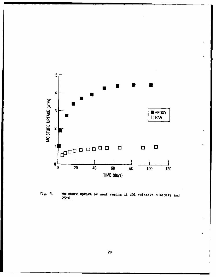
4. Moisture uptake by neat resins at 80% relative humidityand 25*C ......................................................... 20
5. Weight loss of PAA and phenolic resin as a functionof temperature ................................................... 22
6. Pyrolysis shrinkage of neat PAA and phenolic resin ............... 23
7. Photograph of a localized erosion pocket in carbon-phenolic nozzle and throat structure of the STS-8A solidbooster, indicating unstable ablation ............................ 25
8. Chemical structure of phenolic resin ............................. 26
9. The composition and relative amounts of gases releasedduring pyrolysis of neat PAA and phenolic resin,measured by gas chromatography mass spectrometry ................. 28
10. Results of comparative ablation tests, performed at NASA MFSC,of carbon-fabric-reinforced PAA made in MSL and standardphenolic ablative insulator materials ............................ 30
5

I. INTRODUCTION
Polyarylacetylene (PAA) is a highly cross-linked aromatic polymer that
contains only carbon and hydrogen. Its principal advantage is that only
about 10 wt% is volatilized when the polymer is heated to high temperatures
in an inert environment; the remaining 90 wt% is carbon char. Realizing
the benefit of this high char yield in high-performance space system
components has required a major research and development program.
As part of this long-term, continuing program, the Materials Sciences
Laboratory (MSL) of The Aerospace Corporation is currently investigating
PAA for its potential use in dimensionally stable space system composite
structures, as a superior ablative insulator for solid-rocket-motor nozzles
and exit cones, and as a precursor for low-cost carbon-carbon (C-C) compos-
ite structures.
This report presents a brief history of PAA resins (Section II) and
the materials and processing challenges that were met to achieve an
engineering material (Section III). Space system applications of PAA
composites are then described (Section IV). Finally, the recent accom-
plishments of the MSL development program are summarized in Section V.

II. A BRIEF HISTORY OF POLYARYLACETYLENE RESINS
Polyarylacetylene was first synthesized in the late 1950s at the GE
Research Laboratory as part of a broad search for polymers with high char
yield. I During cure, that early formulation underwent severe shrinkage and
released large amounts of heat (exothermic reaction). Such processing
difficulties precluded the practical application of that material. In the
early 1960s, techniques for reducing both the exotherm and extent of
shrinkage during polymer curing were demonstrated at Cyanamid Corp.2 How-
ever, those techniques were not applied to PAA until the early 1970s, when
Hercules patented a process for the production of PAA from diethynylbenzene
(DEB) monomer for use as a high-temperature molding compound (designated HA
43 by Hercules). 3 HA 43 was made available in pilot-plant quantities for
evaluation by the technical community. The Aerospace Corporation used it
to produce a carbon-fabric-reinforced ablative thermal protection system.
Although they ablated satisfactorily, the composites were brittle and had
poor structural integrity. Further research at Aerospace demonstrated HA
43 to be a suitable carbon matrix precursor for special x-ray-absorbing
carbon-carbon nuclear shields. The Defense Nuclear Agency (DNA) then
funded MSL to direct a program to construct and evaluate thin-walled x-ray-
absorbing C-C composites. Samples of those composites were evaluated in
aboveground and underground test environments and exhibited excellent
survivability.4
In the early 1980s, growing requirements for laser countermeasures
stimulated the current PAA research program at Aerospace. MSL found that
the Hercules-patented molding material lacked the plasticity to make plies
of material impregnated with resin (prepreg). The fabrication of large
parts by standard techniques was thus prohibited. Although the Hercules
patent teaches that addition of low molecular weight materials can provide
sufficient plasticity for effective molding of the high molecular weight
prepolymer at reasonable pressures, research in MSL showed that such low
molecular weight materials are not incorporated into the final polymer.
9

Consequently, a structurally poor composite with low strain capability
(brittleness) and reduced char yield is produced.
The Materials Sciences Laboratory program was designed to correct
these deficiencies. They were overcome by the development of a controll-
able, low-temperature prepolymeri2ation technique that produces a soluble,
easy-to-process prepolymer. We demonstrated that polymer-chain modifica-
tions to improve ductility and toughness can be incorporated during pre-
polymer synthesis, resulting in composites with high char yield and good
mechanical properties.5 Detailed accomplishments in MSL's PAA material and
process development are discussed in the following sections.
10

III. MATERIAL AND PROCESS DEVELOPMENTS FOR PAA COMPOSITES
In the MSL technique for fabrication of PAA-based carbon-fiber-
reinforced composites, shown in Fig. 1, a solution of meta- and para-DEB
monomer is first cyclotrimerized into a low molecular weight prepolymer.
In cyclotrimerization, three acetylene groups (from three different monomer
molecules) react to form a benzene ring. Carbon fiber tows or woven
fabrics are then coated with the prepolymer to produce a prepreg unidirec-
tional tape or woven fabric. This prepreg can be wrapped or wound or
stacked and formed into the desired shape by conventional lay-up
procedures, and the polymer can be cured under moderate pressure (100-200
psi) at a relatively low temperature (100-150°C). The resin matrix
composites can then be used as primary structures or they can be heat-
treated to carbonize or graphitize the resin to form a relatively high-
density C-C composite.
Processing problems that required solution were (1) characterizing and
controlling the purity of the monomer; (2) developing a prepolymer with the
proper degree of cyclotrimerization to yield solublE, stable material with
the required rheological characteristics; and (3) controlling the process-
ing for prepreg lay-up, consolidation, and curing. Each of the PAA
composite fabrication steps is detailed below.
A. MONOMER
All of the DEB monomer used in the early work in MSL was synthesized
in small batches in our laboratory. Thus, the size of composite articles
that could be fabricated and studied was seriously limited. In 1988, we
learned that Hercules had stored about 150 kg of DEB remaining from their
production of HA 43 resin. We purchased 50 kg of that material, which en-
abled us to fabricate and test large-scale composite parts. (A reliable
supply of material is expected to become available soon, since Hercules
recently announced that they will manufacture both DEB monomer and cyclo-
trimerized prepolymer.)
11

CYCLOTRIMERIZATION N
NICKEL CATALYST
META- AND PARA- INDIETHYNYLBENZENE (DEB) POLYARYLACETYLENE (PAA)
MONOMER "RPLMR
PREPREG FIBERTOWS OR FABRIC
LAY-UP COMPOSITE INCARBONIZATION
(100-C CARBON-CARBONCURE ~ - ~ -- GRAPHITIZATION COMPOSITES
(heat, pressure) I(2400-2800-C) EXII FONT
SPAC[ CRAIS IRIC r IR H(1
MIRROR SUIYRAI
PAA POLYMER HIGH TEMP[TRR
COMPOSITES SIRUCILRTS
SPACECRAFTSTRUCTURES
ABLATIVEEXIT CONES
Fig. 1. Schematic of fabrication of polyarylacetylene composites.
12

Successful fabrication of PAA composite parts requires that the DEB
monomer be of high purity so that the formation and subsequent outgassing
of volatile by-products is reduced during composite fabrication and use
Standard analytical methods and separation techniques were found to be
inadequate to characterize monomer purity. However, we were able to
demonstrate that monomer isomers and their by-products are readily
distinguishable by proton nuclear magnetic resonance (pNMR) spectroscopy.
Figures 2a and 2b are NMR spectra of 99% isomerically pure para- and meta-
DEB synthesized in MSL. Figure 2c is a spectrum of DEB received from
Hercules; the sharp singlets at 3.1 and 3.2 ppm and the region centered at
7.4 ppm in Fig. 2c are predominantly due to a mixture of meta- and para-
isomers in a 3:2 ratio. The other resonances below 3 ppm represent
impurity by-products (ethyl, vinyl, and ethynyl substituents), which can be
quantitatively determined by peak area ratios. Such impurities are unde-
sirable for PAA composite fabrication. We have used pNMR to verify and
control the purity of the monomer received from Hercules.
B. PREPOLYMER
The cyclotrimerization step is designed to produce a soluble solid
that melts at a temperature lower than the onset of cure. Cyclotrimeriza-
tion is important because it produces resonance-stable benzene rings that
govern both the thermal stability of the system and the high char yield on
pyrolysis. It is an exothermic reaction; therefore, part of the heat of
polymerization is liberated during this step, resulting in a milder and
more controllable exotherm during final cure. In addition, part of the
shrinkage that accompanies curing occurs during cyclotrimerization.
Successful PAA composite processing requires that the prepolymerization be
stopped when the reaction has proceeded to the required point. Too little
reaction negates the benefits of the cyclotrimerization step; on the other
hand, a reaction permitted to proceed too far forms a prepolymer that is
very difficult to process. It is also crucial to prevent the occurrence of
a reaction which competes with cyclotrimerization: linear polymerization.
Linear polymerization results in a polymer with reduced thermal stability
and char yield.
13

Para-DEB monumer
z (a)
I 1 I 2 I I I I I ,
Meta-DEBmonomer
,z (b)I~z
Hercules DEB monomer
C,z (c)z
8 7 6 5 4 3 2 1 0CHEMICAL SHIFT
(parts per million)
Fig. 2. Proton nuclear magnetic resonance (pNKR) spectra of DEB:spectra of 99% isomerically pure (a) para-DEB and (b) meta-DEB,synthesized in MSL; and (c) spectrum of DEB received fromHercules.
114

We established that methyl ethyl ketone (MEK) is a better solvent for
the cyclotrimerization reaction than the previously used toluene. The use
of MEK results in rapid reaction, and its low boiling point enables good
process control. In 1989, we demonstrated the use of infrared (IR) spec-
troscopy to monitor and control the prepolymer reaction. In this tech-
nique, the ratio of the intensities of an IR peak associated with the
synthesized prepolymer (at 1600 cm-1 due to ring-to-ring C-C stretching) to
that of an IR peak from the acetylenic groups that are being consumed (CEH
stretching at 3256 cm-1), is monitored as the reaction proceeds. The ratio
of intensities of these two peaks at various reaction times has been
correlated with the processability of the resulting prepolymer, and an
optimum ratio has been determined.
The chemical structure of the MSL prepolymer and the possible presence
of undesirable linear polymerization were investigated with pNMR spectros-
copy. A pNMR spectrum of the prepolymer is shown in Fig. 3. Linear poly-
merization would be indicated by the presence of olefinic protons in the
spectral region between 5.3 and 6.8 ppm. The spectrum shows no detectable
peaks in this region, confirming that no linear polymerization has
occurred.
C. PREPREG
In the next step of the PAA composite fabrication process, either
fiber tows or woven fabric is impregnated with the prepolymer solution and
the MEK solvent is evaporated, leaving a prepreg tape or fabric. The
handleability of this prepreg is crucial for good composite fabrication:
The prepreg must be easy to drape over curved surfaces and be tacky enough
to keep the prepreg layers from moving in relationship to each other. The
resin must also melt and flow before curing to completely impregnate and
nonsolidate the laminated preform.
We have successfully developed a procedure for controlling drape,
tackiness, and flow of the prepreg. Phenylacetylene, a chemical analog of
DEB, contains only a single active acetylene group and can be cocyclotri-
merized with the DEB. This coprocessing leads to a prepolymer that is less
15

REGION FROM 5.0 TO 8.0 ppm IS MAGNIFIED 7.9x
ARYL HYDROGENS
ACETY LEN ICHYDROGENS
8.0 7.5 7.0 6.5 6.0 5.5 5.0 4.5 4.0 3.5 3.0 2.5 2.0 1.5 1.0 0.5 0. 0CHEMICAL SHIFT (parts per million)
Fig. 3. Proton nuclear magnetic resonance spectrum of PAA prepolymersvnthesi2ed in 14SL.
16

cross-linked and, therefore, less viscous when melted. To further control
the flow properties, DEB monomer can be blended with the prepolymer,
compensating for any monomer or prepolymer variation. We have found that
such blending does not decrease the high pyrolysis char yield of the cured
resin.
D. CURE
The PAA composite lay-up may be cured by conventional vacuum-bag proc-
essing, in an autoclave, hydroclave, or press. No special tooling or
apparatus is required.
17

IV. APPLICATIONS OF PAA MATRIX COMPOSITES
PAA resin matrix composites are being investigated in MSL for several
potential applications, including (1) conventional resin matrix composites
with ultralow-moisture outgassing characteristics and improved dimensional
stability for spacecraft structures, (2) precursors for carbon-carbon com-
posites, and (3) ablative insulators for solid rocket motors.
A. SPACECRAFT STRUCTURES
The main motivation for investigating PAA as a matrix for carbon
fibers in spacecraft structural materials is the very low moisture absorp-
tion and outgassing of PAA resin. Materials with low moisture absorption
are not subject to gradual dimensional change with changes in humidity.
Moreover, in space there will be no evolution and condensation of moisture
on sensors and mirrors to degrade performance and limit mission life. The
graphite-epoxy composites currently used for space structures display
excessive moisture absorption because of the hydrophilic nature of epoxy
resins. These contain numerous polar functional groups, such as hydroxyls
and amino groups, that readily hydrogen-bond with water. In contrast, PAA
is hydrophobic, which means that it contains no such polar groups. As a
result, it absorbs relatively little moisture, as shown in Fig. 4.
We have determined that the strength and modulus of carbon-fiber-
reinforced PAA composites are comparable to those of graphite-epoxy. Mass
loss and collected volatile condensable material testing of PAA composites
was performed in accordance with ASTM and NASA specifications, and PAA
composite outgassing was well below acceptable limits.
B. CARBON-CARBON COMPOSITES
Carbon-carbon composites offer outstanding thermodynamic and
dimensional stability over wide temperature ranges and are resistant to
laser and nuclear threats. They are used currently in a number of DoD
space systems and have replaced previously used monolithic polycrystalline
graphite in several solid-rocket-motor throat inserts to provide superior
19
5
4 U
LU 33e N EPOXY
•c PAAUiU
cc 2= iFY
CD,
0 I I I I I0 20 40 60 80 100 120
TIME (days)
Fig. 4. Moisture uptake by neat resins at 80% relative humidity and250 C.
20

reliability. They are in production for lightweight exit cones in
ballistic missile boosters and in the IUS, and are under development or
consideration for a number of emerging systems. C-C composites are now
also being considered for survivable spacecraft structural applications in
future systems, such as large space structures and mirror substrates.
The major problem in existing systems is cost. Conventional C-C proc-
essing requires four to six months to complete a typical component and
achieves the required material density by repeated and lengthy impregnation
and high-temperature heat-treatment cycles. Such processing is very
costly, and the schedule effect of discrepancies and process mishaps is
extreme because of the long time needed to fabricate replacement hardware.
PAA resins are particularly attractive as carbon matrix precursors
because their very high carbon yields can eliminate or reduce the multiple
impregnation cycles required of current precursors. Figure 5 illustrates
the superior char yield of PAA over that of currently used phenolic. The
costly multiple impregnation cycles also increase the likelihood of pro-
cessing failures and contribute to fiber-strength degradation. Relatively
low volume shrinkage upon carbonization (Fig. 6) is another attractive
feature of PAA resins. Matrix shrinkage is thought to reduce composite
strength by introducing surface defects into the fibers.
Carbon-carbon composites containing either carbon fibers or fabric
reinforcements utilizing PAA resin as the carbon matrix precursor have been
fabricated and evaluated in MSL. 6 They exhibit good mechanical properties
and dimensional integrity after carbonization and graphitization, requiring
no additional reimpregnation and carbonization cycles to achieve these
desirable properties.
C. ABLATIVE COMPONENTS FOR SOLID ROCKET MOTORS
Carbon-phenolic (C-Ph) and graphite-phenolic (Gr-Ph) materials are
currently used for ablative and insulative components of booster nozzles
and exit cones in Titan, Delta, Shuttle, and MX solid rocket motors
(SRMs). Ideally, these materials should exhibit repeatable, predictable,
uniform recession rates at the flame surface and should thermally insulate
21

100- A
LUI-
50---
I I I I I
0 500 1000TEMPERATURE (°C)
Fig. 5. Weight loss of PAA and phenolic resin as a function oftemperature. The weight of material remaining after heating tohigh temperatures in an inert environment is termed char yield.
22

+4
0-
-4-- PAA
-12ccPENOLIC
Cn.
-16-
-20
-24 I 1 I 1 i I -q0 100 200 300 400 500 600 700 800
TEMPERATURE (0C)
Fig. 6. Pyrolysis shrinkage of neat PAA and phenolic resin. At 7500C,PAA has undergone less than half the shrinkage of the phenolicresin. The positive volume change at lower temperatures is dueto swelling caused by polymer degradation.
23

the backside structure as well. In operation, however, the ablation
behavior of phenolic matrix ablative materials has been variable and
unstable, posing doubts about the true system reliability. Although no
system failures have been attributed to the behavior of these phenolic
materials, the more serious incidents have led to costly redesign and
recovery efforts.
The best-known example of unstable ablation is the "pocketing" dis-
covered in the C-Ph nozzle components recovered from the STS-8A booster
(Fig. 7). Localized deep pockets in a regular array were found. In the
worst region, only a few seconds of burn-through life margin remained.
NASA conducted a major materials investigation and redesign effort to avoid
recurrence, and initiated evaluation of material replacements. However,
incidents of less severe pocketing have been reported for subsequent STS
flights. More recently, Titan IV static tests revealed unstable ablation
in two localized zones opposite the exit cone O-ring seal. Although
booster performance was otherwise nominal, unstable ablation eroded the
phenolic material as far as the 0-ring seal groove, leaving zero margin.
Other examples of unexplained and disturbing incidents of erosion
pits, shallow craters, and grooves have accompanied unexpected and unpre-
dictable ablation. Some solid motor test anomalies have also been
attributed to the large amounts of evolved pyrolysis gases generated by the
phenolic matrix materials. Inadequate management of pyrolysis gas can lead
to extremely high pressures within the composite materials. The forces
exerted by such pressures exceed the design capability of nozzle compo-
nents, causing expulsion of gas and buckling of exit cones. In a dramatic
example (D5 program), such forces propelled the throat section forward at
the end of burn, causing the section to violently strike the chamber nozzle
forward dome.
Such problems result from the hydrophilic nature of phenolic resins
(Fig. 8), which cure by a condensation reaction that has water as a by-
product and also readily absorb moisture. The absorbed moisture acts as a
plasticizer and lowers the interlaminar load-carrying capacity of the
24

5 in.
Fig. 7. Photograph of a localized erosion pocket in carbon-phenolicnozzle and throat structure of the STS-8A solid booster,indicating unstable ablation. Arrow indicates worst-caseerosion, in which only a few seconds of life remained beforeburn-through.
25

OH OH
CH
OH CH2 OH
-x- NCHI
N
Fig. 8. Chemical structure of phenolic resin.
26

resin. During ablative heating, the moisture is vaporized and causes pres-
sure to build up within the composite, resulting in an array of internal
delaminations (ply lifts) that extends to the outer surface, causing local
sloughing and enhanced ablation. That pressure is in addition to the
pressure caused by the large amount of volatile hydrocarbons from pyrolysis
of the resin itself, which has a char yield of only about 50%. These vola-
tiles can be thermally cracked, resulting in carbon deposition and plugging
of gas-diffusion paths, and hence greater internal pressure buildup.
Pressure in the pores can also cause tensile failure of the yarns, leading
to ejection of chunks of unattached material and localized pockets. More-
over, the residual phenolic char has no useful load-carrying capacity.
In contrast, the hydrophobic PAA resin does not absorb much moisture
and cures by an addition reaction that has no by-products. Its char yield
of about 90% means that far less volatile material is generated and that
minimal shrinkage is associated with pyrolysis. We measured the composi-
tion and relative amounts of gases released durirn6 pyrolysis of PAA neat
resins using gas chromatography mass spectrometry (Fig. 9).7 The dominant
gas evolved by PAA is hydrogen, the amount of which peaks at 8000C. In
contrast, the gaseous pyrolysis products of phenolic resin are dominated by
high molecular weight hydrocarbons, as well as oxygen-containing hydro-
carbons, that peak at the lower temperature of 5000C. Since most of the
PAA pyrolysis gas is hydrogen, hydrocarbon cracking and pore plugging are
diminished. Moreover, the high char yield of PAA results in useful
strength of the remaining char. Preliminary testing shows the PAA char to
be smooth and uniform.
As part of current NASA programs for SRM redesign and improved solid
propulsion integrity, NASA Marshall Space Flight Center (MSFC) investigated
PAA composites fabricated by MSL. The tests included thermophysical char-
acterization of the material at Southern Research Institute8 and compara-
tive arcjet ablation testing at MSFC. Two exceptionally thick (2-1/2-in.)
carbon-fiber-reinforced PAA composite test billets were fabricated in MSL
utilizing PAN-precursor T300 woven carbon fabric as the reinforcement. Our
fabrication procedures were demonstrated by these thick billets to be
27

30PM
HYDROGEN
= 20 HIGHER MWAROMATIC
_ HYDROCARBONS (a)0LU
- 10"-i METHANE / .
01200 400 600 800 1000 1200
TEMPERATURE (-C)80
PHENOLIC HIGHER MW60- iHYDROCARBONS
Cd /LU / -OXYGENATEDI-- /,z 40 / HYDROCARBONS (b)
LU , CO + C02/ -,
LU 20 -cc . N METHANE
200 400 600 800 1000 1200 1400TEMPERATURE (°C)
Fig. 9. The composition and relative amounts of gases released duringpyrolysis of (a) neat PAA and (b) pl,.hnolic resin, measured bygas chromatography mass spectrometry.
28

suitable for practical nozzle parts and also provided a material whose
thermophysical properties could be characterized at both the surface and in
the thick part's interior.
NASA performed comparative ablation tests with a CO2 plasma jet. The
ablation tested by this method has been shown to correlate well with re-
cession rates in full-scale motor test firings. The results for PAA com-
posites, as well as for C-Ph (Fig. 10), indicate that PAA is markedly
superior--it undergoes less weight loss and erosion--and that PAA data vary
much less than those for C-Ph. Also, whereas a large fraction of the C-Ph
samples exhibited pocketing, there was no pocketing in any of the PAA
samples. NASA currently plans larger scale testing of PAA composites.
29

6
5 U
4UU..) UU./)._ 3 0 T300/PAA- 3
N CARBON/PHENOLICS2-
0 CI] PAA[0
00 0.1 0.2 0.3 0.4 05EROSION (in.)
Fig. 10. Results of comparative ablation tests, performed at NASA MFSC,of carbon-fabric-reinforced PAA made in MSL and standardphenolic ablative insulator materials. Specimens were exposedfor 10 sec in a high-intensity CO2 arcjet under standardizedconditions.
30

V. SUMMARY
We have made significant progress in our long-term effort to develop
the processing for and to demonstrate the practical application of PAA-
based composites. We succeeded in developing a procedure for synthesizing
PAA prepolymer, and we established the chemistry of each major processing
step required to prepare composite prepreg. The prepreg was used to fabri-
cate large-scale samples and was also demonstrated to be a practical (fast
and easy-to-control) precursor for C-C composites. PAA offers promise as a
potential low-cost alternative for such composites.
The performance demonstrated in the NASA ablation tests, and NASA's
commitment to explore PAA as a part of the next generation of solid
boosters, is extremely encouraging. This and other applications of the
material will be pursued in the course of our continuing studies of PAA
composites.
31

REFERENCES
1. A. S. Hay, "Preparation of m- and p- Diethynyl Benzenes," J. Org.Chem. 25, 637 (1960).
2. L. S. Meriwether et al., "Polymerization of Acetylenes by Nickel-Carbonyl-Phosphine Complexes," J. Org. Chem. 27, 3930 (1962).
3. H. Jabloner, "Poly(arylacetylene) Molding Compositions," U.S. PatentNo. 4,070,333 (24 January 1978).
4. Carbon-Carbon Composites for Protective Shielding, Report 2274-78,HAVEG Corp. (19 July 1978) (DNA Contract No. DNA-O01-77-C-0056,Unclassified).
5. W. T. Barry et al., Review of Polyarylacetylene Matrices for Thin-Walled Composites, Report TR-0089(4935-06)-I, The Aerospace Corp., ElSegundo, CA (25 September 1989).
6. G. A. Binegar et al., Effects of Heat Treatment on Microstructure andFlexural Properties of Unidirectional Carbon-Carbon Composites, ReportTR-0089(4935-06)-2, The Aerospace Corp., El Segundo, CA (1 November1989).
7. M. P. Easton and D. Gilmartin, "Pyrolysis Gas Chromatography MassSpectrometry of Polyarylacetylene Resins," Paper presented 37th ASMSConference on Mass Spectrometry and Allied Topics, Miami Beach, FL,21-26 May 1989.
8. D. R. McCurdy and J. R. Koenig, Selected Physical, Mechanical, andThermal Properties of a Polyarylacetylene Composite, Report SRI-MME-89-207-6526-11, Southern Research Institute (March 1989).
33

LABORATORY OPERATIONS
The Aerospace Corporation functions as an "architect-engineer" for national securityprojects, specializing in advanced military space systems. Providing research support, thecorporation's Laboratory Operations conducts experimental and theoretical investigations thatfocus on the application of scientific and technical advances to such systems. Vital to the successof these investigations is the technical staff's wide-ranging expertise and its ability to stay currentwith new developments. This expertise is enhanced by a research program aimed at dealing withthe many problems associated with rapidly evolving space systems. Contributing their capabilitiesto the research effort are these individual laboratories:
Aerophysics Laboratory: Launch vehicle and reentry fluid mechanics, heat transferand flight dynamics; chemical and electric propulsion, propellant chemistry, chemicaldynamics, environmental chemistry, trace detection; spacecraft structural mechanics,contamination, thermal and structural control; high temperature thermomechanics, gaskinetics and radiation; cw and pulsed chemical and excimer laser development,including chemical kinetics, spectroscopy, optical resonators, beam control, atmos-pheric propagation, laser effects and countermeasures.
Chemistry and Physics Laboratory: Atmospheric chemical reactions, atmosphericoptics, light scattering, state-specific chemical reactions and radiative signatures ofmissile plumes, sensor out-of-field-of-view rejection, applied laser spectroscopy, laserchemistry, laser optoelectronics, solar cell physics, battery electrochemistry, spacevacuum and radiation effects on materials, lubrication and surface phenomena,thermionic emission, photosensitive materials and detectors, atomic frequency stand-ards, and environmental chemistry.
Electronics Research Laboratory: Microelectronics, solid-state device physics,compound semiconductors, radiation hardening; electro-optics, quantum electronics,solid-state lasers, optical propagation and communications; microwave semiconductordevices, microwave/millimeter wave measurements, diagnostics and radiometry, micro-wave/millimeter wave thermionic devices; atomic time and frequency standards;antennas, rf systems, electromagnetic propagation phenomena, space communicationsystems.
Materials Sciences Laboratory: Development of new materials: metals, alloys,ceramics, polymers and their composites, and new forms of carbon; nondestructiveevaluation, component failure analysis and reliability; fracture mechanics and stresscorrosion; analysis and evaluation of materials at cryogenic and elevated temperaturesas well as in space and enemy-induced environments.
Space Sciences Laboratory: Magnetospheric, auroral and cosmic ray physics,wave-particle interactions, magnetospheric plasma waves; atmospheric and ionosphericphysics, density and composition of the upper atmosphere, remote sensing usingatmospheric radiation; solar physics. infrared astronomy, infrared signature analysis;effects of solar activity, magnetic storms and nuclear explosions on the earth'satmosphere, ionosphere and magnetosphere; effects of electromagnetic and particulateradiations on space systems; space instrumentation.