object-oriented software engineering practical software development using uml and java architecting...
TRANSCRIPT
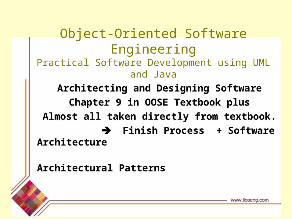
Object-Oriented Software EngineeringPractical Software Development using UML and Java
Architecting and Designing Software
Chapter 9 in OOSE Textbook plus
Almost all taken directly from textbook.
Finish Process + Software Architecture
Architectural Patterns
© Lethbridge/Laganière 2001 26 Chapter 9: Architecting and designing software 2
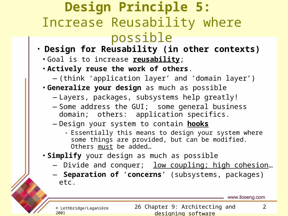
Design Principle 5: Increase Reusability where possible
• Design for Reusability (in other contexts) • Goal is to increase reusability; • Actively reuse the work of others.
—(think ‘application layer’ and ‘domain layer’)• Generalize your design as much as possible
—Layers, packages, subsystems help greatly!—Some address the GUI; some general business domain; others:
application specifics. —Design your system to contain hooks
- Essentially this means to design your system where some things are provided, but can be modified. Others must be added…
• Simplify your design as much as possible — Divide and conquer; low coupling; high cohesion…— Separation of ‘concerns’ (subsystems, packages) etc.

© Lethbridge/Laganière 2001 26 Chapter 9: Architecting and designing software 3
Design Principle 6: Reuse existing designs and code where possible
• Design with Reuse is Complementary to Design for Reusability
• Actively reusing designs or code allows you to take advantage of the investment you or others have made in reusable components

© Lethbridge/Laganière 2001 26 Chapter 9: Architecting and designing software 4
Design Principle 7: Design for flexibility
•These are particularly good!!
•Actively anticipate changes that a design may have to undergo in the future, and prepare for them
Reduce coupling and increase cohesion of design elements
• Create abstractions like interfaces or super classes.
—Readily supports extensions and polymorphism
• Do not hard-code anything
—Remember, programming is the realization of design!!!
—This is not the time…
• Use reusable code and make code reusable (where practical…)

© Lethbridge/Laganière 2001 26 Chapter 9: Architecting and designing software 5
Design Principle 8: Anticipate obsolescence
• Plan for changes in the technology or environment so the software will continue to run or can be easily changed
Avoid using early releases of technology
—NEVER a good idea to use unproven technologies…
• Avoid using software libraries specific to particular environments – may not be supported in the future…
• Avoid using undocumented features or little-used features of software libraries
Avoid using software or special hardware from companies that are less likely to provide long-term support
Use standard languages and technologies that are supported by multiple vendors

© Lethbridge/Laganière 2001 26 Chapter 9: Architecting and designing software 6
Design Principle 9: Design for Portability
• Have software run on as many platforms as possible • Avoid use of facilities specific to one particular environment
—e.g. a library only available in Microsoft Windows
• Remember: we develop systems that will hopefully be used ‘for a long time.’ Platforms change!
• But: more and more technologies are here and coming along which support portability very nicely….
—Don’t want to care how many bits there are in an integer or key definitions that apply only in a special environment.
—Be aware of these in your design decisions / choices.

© Lethbridge/Laganière 2001 26 Chapter 9: Architecting and designing software 7
Design Principle 10: Design for Testability
•Take Steps to make Testing Easier• Map your tests to use-cases
• Map the validation of your prototype to use cases.
• Design each test back to
• demonstrate satisfaction of functional / non-functional requirements
• One may design a program to automatically test the software
—Discussed more in Chapter 10
• Study the testing discipline and be aware of the many faces of testing…many techniques.

© Lethbridge/Laganière 2001 26 Chapter 9: Architecting and designing software 8
Design Principle 11: Design Defensively
• Never trust how others will try to use a component you are designing
• Handle all cases where other code might attempt to use your component inappropriately
• “Robustness” – Discuss tradeoffs and criticality…
• Check the validity of all inputs to your components
—the preconditions
—Unfortunately, over-zealous defensive design can result in unnecessarily repetitive checking
• More on Robustness:
—The 80-20 rule
—Many ‘absolutely necessary’ features are never used; rather, test for ‘desired outcomes!’

© Lethbridge/Laganière 2001 26 Chapter 9: Architecting and designing software 9
Note:
•Be certain to read through and study the next section:
9.3 Techniques for making good design decisions.
•Conscientious professionals record their design decisions!
•We will advance to section 9.4: Software Architecture. (five slides ahead)
© Lethbridge/Laganière 2001 26 Chapter 9: Architecting and designing software 14
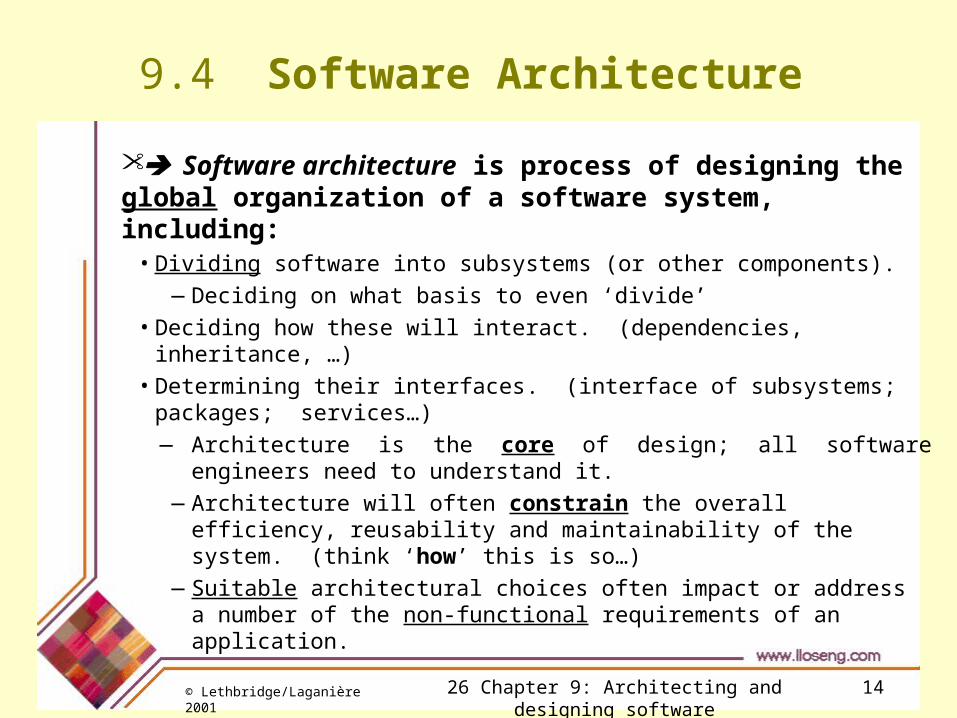
9.4 Software Architecture
Software architecture is process of designing the global organization of a software system, including:
• Dividing software into subsystems (or other components).
—Deciding on what basis to even ‘divide’
• Deciding how these will interact. (dependencies, inheritance, …)
• Determining their interfaces. (interface of subsystems; packages; services…)
—Architecture is the core of design; all software engineers need to understand it.
—Architecture will often constrain the overall efficiency, reusability and maintainability of the system. (think ‘how’ this is so…)
—Suitable architectural choices often impact or address a number of the non-functional requirements of an application.

© Lethbridge/Laganière 2001 26 Chapter 9: Architecting and designing software 15
The importance of software architecture*
•Why Develop an Architectural Model? • To enable everyone to better understand the system
—Particularly true for large, distributed, complicated systems—Provides a view where developers can ‘see’ their part(s)
• To allow people to work on individual pieces of the system in isolation• To prepare for extension of the system • To facilitate reuse and reusability
Software architecture is the process of designing the global organization of a system,
including breaking up the system into subsystems, deciding how these will interact, and determining their interfaces.
The documentation of all this is called the architectural model.

© Lethbridge/Laganière 2001 26 Chapter 9: Architecting and designing software 16
Contents of a good architectural model
•A system’s architecture is often expressed in a number of different views that are high level.
© Lethbridge/Laganière 2001 26 Chapter 9: Architecting and designing software 17
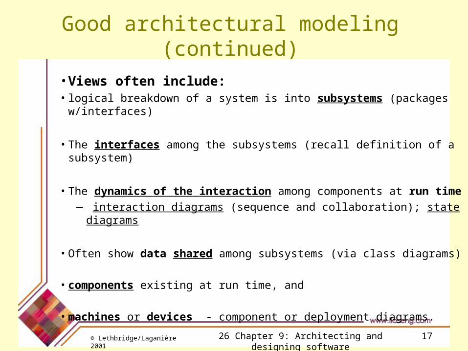
Good architectural modeling (continued)
• Views often include:• logical breakdown of a system is into subsystems (packages w/interfaces)
• The interfaces among the subsystems (recall definition of a subsystem)
• The dynamics of the interaction among components at run time
— interaction diagrams (sequence and collaboration); state diagrams
• Often show data shared among subsystems (via class diagrams)
• components existing at run time, and
• machines or devices - component or deployment diagrams.
© Lethbridge/Laganière 2001 26 Chapter 9: Architecting and designing software 18
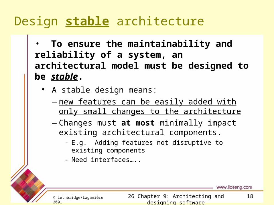
Design stable architecture
• To ensure the maintainability and reliability of a system, an architectural model must be designed to be stable.
• A stable design means:
—new features can be easily added with only small changes to the architecture
—Changes must at most minimally impact existing architectural components.
- E.g. Adding features not disruptive to existing components
- Need interfaces…..

© Lethbridge/Laganière 2001 26 Chapter 9: Architecting and designing software 19
Developing an architectural model
•Start by sketching an outline of the architecture• Based on the principal requirements and use cases Determine the main components that will be needed
—Databases; main software subsystems - (i.e. main hunks of functionality); - Let your use-case packages assist you!
—Specific hardware/software, if needed; Choose among the various architectural patterns
—Discussed in the next lecture.—Requires understanding of architectural layers, modules, and
a number of related options; interfaces; ‘concerns’ ….• Suggestion: have several different team members independently
sketch a first draft of the architecture and merge together the best ideas
© Lethbridge/Laganière 2001 26 Chapter 9: Architecting and designing software 20
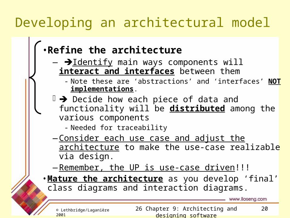
Developing an architectural model
• Refine the architecture— Identify main ways components will interact and
interfaces between them- Note these are ‘abstractions’ and ‘interfaces’ NOT
implementations. Decide how each piece of data and functionality will
be distributed among the various components- Needed for traceability
—Consider each use case and adjust the architecture to make the use-case realizable via design.
—Remember, the UP is use-case driven!!!• Mature the architecture as you develop ‘final’ class
diagrams and interaction diagrams.

© Lethbridge/Laganière 2001 26 Chapter 9: Architecting and designing software 21
Describing an architecture using UML
• All UML diagrams are useful to describe aspects of architectural model
• Remember, this is to be done at a high level to indicate software components and their interfaces
Use cases provide a good summary from the perspective of the user; Class diagrams show the services provided by components
(subsystems…) and the main data that is stored; Interaction diagrams show the main protocols used when components
interact with each other.
• Four UML diagrams are particularly suitable for architecture modelling:
—Package diagrams
—Subsystem diagrams
—Component diagrams
—Deployment diagrams

© Lethbridge/Laganière 2001 26 Chapter 9: Architecting and designing software 22
Package diagrams
common
simplechat1 ocsf
client
server
client «imports»
• A Package is a group of model elements placed together because they are logically related.• A Java package is only a collection of classes. But this ‘can’ be a package in UML and we use this as an example.
Here, the packages contain other packages. Packages can contain anything…• Individual components should subscribe to ensuring elements exhibit cohesion and coupling.• Cohesion (high) components contain elements that are closely related in some way• Provide a capability all of which classes contribute to this capability, or what have you.• Coupling (low) decrease the number of dependencies of its model elements. Provides for replacement of components with minimal impact (preferably none)Remember: packages do not have a single interface; rather, the interfaces are on the individual components – unlike subsystems..
© Lethbridge/Laganière 2001 26 Chapter 9: Architecting and designing software 23
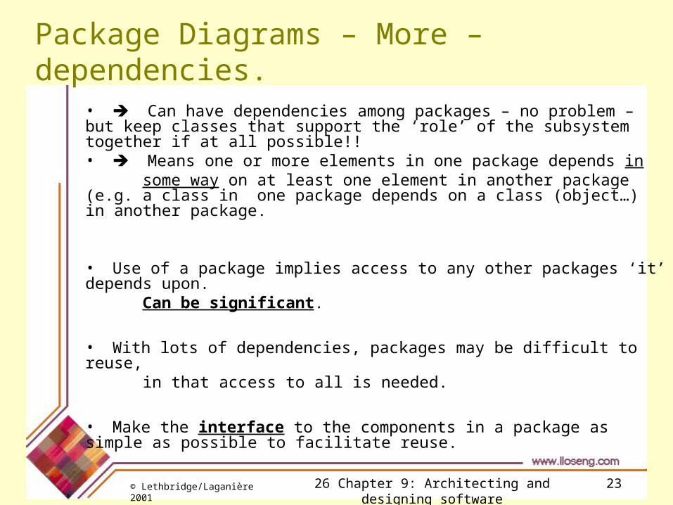
Package Diagrams – More – dependencies.
• Can have dependencies among packages – no problem – but keep classes that support the ‘role’ of the subsystem together if at all possible!!• Means one or more elements in one package depends in
some way on at least one element in another package (e.g. a class in one package depends on a class (object…) in another package.
• Use of a package implies access to any other packages ‘it’ depends upon.
Can be significant.
• With lots of dependencies, packages may be difficult to reuse, in that access to all is needed.
• Make the interface to the components in a package as simple as possible to facilitate reuse.
© Lethbridge/Laganière 2001 26 Chapter 9: Architecting and designing software 24
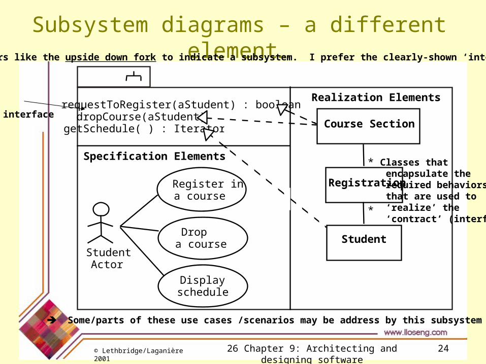
Subsystem diagrams – a different element…
requestToRegister(aStudent) : booleandropCourse(aStudent)getSchedule( ) : Iterator
Register in a course
Student Actor
Display schedule
Drop a course
***** Course Section
*
*
Registration
Student
Realization Elements
Specification Elements
These authors like the upside down fork to indicate a subsystem. I prefer the clearly-shown ‘interface class.’
interface
Some/parts of these use cases /scenarios may be address by this subsystem
Classes that encapsulate the required behaviors that are used to ‘realize’ the ‘contract’ (interface)

© Lethbridge/Laganière 2001 26 Chapter 9: Architecting and designing software 25
Subsystem Design – much more…
• Subsystems - a much more formal structure than packages.
• The operations (the interface) e.g. signature of subsystem is the interface.
—This is the ‘contract’ with clients of the subsystem
• The specification elements (like a use case diagram or scenarios),
—Basis for deciding on main functionality of the subsystem; and a
• Realization elements (class diagram or interaction diagram)
—Shows how the subsystem components realize contract.
© Lethbridge/Laganière 2001 26 Chapter 9: Architecting and designing software 26
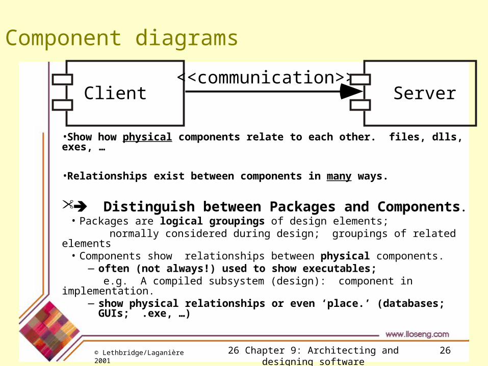
Component diagrams
•Show how physical components relate to each other. files, dlls, exes, …
•Relationships exist between components in many ways.
Distinguish between Packages and Components.• Packages are logical groupings of design elements;
normally considered during design; groupings of related elements• Components show relationships between physical components.
—often (not always!) used to show executables; e.g. A compiled subsystem (design): component in implementation.
—show physical relationships or even ‘place.’ (databases; GUIs; .exe, …)
Client Server<<communication>>

© Lethbridge/Laganière 2001 26 Chapter 9: Architecting and designing software 27
Deployment diagrams
•Show the hardware where various instances of components reside at run time.
•Nodes in deployment diagrams represent computational units, like a computer, device,
• This is quite significant for your projects this semester. (CCB, …)
•Links are normally shown to illustrate how these components communicate with each other.
• But even the links (at this time) may be not locked in.
Machine1:TCP/IP
Machine2:GPSSatellite
Wirelesscommunication
Client1:
Client2:Server: