novel formulation for line of sight guidance and obstacle
TRANSCRIPT

Novel Formulation for Line of Sight Guidance and Obstacle Avoidance
for Under-actuated Ships
NASSIM KHALED1, RAMI ALKHATIB2 1Mechanical Engineering Department, Prince Mohammad Bin Fahd University, [email protected],
Al Khobar, Saudi Arabia 2Mechanical and Mechatronics Engineering Department, Rafik Hariri University,
[email protected], Mechref, Damour, Lebanon Abstract: - Automatic control of under-actuated ships is a challenging task due to the external factors and limited actuators onboard a ship. It is even more so when the controller needs to seamlessly integrate with a guidance system and obstacle avoidance for the purpose of autonimity. In this paper, line of sight guidance system for marine surface vessels is augmented to include obstacle avoidance. The process of directing the ship movement to avoid a stationary and moving obstacles is tackled by introducing an iterative mathematical formulation for the circle of avoidance algorithm. Unlike learning based guidance system, the proposed formulation has an explicit solution that is updated at each instant in time. Three simulations are conducted to assess the performance of the overall guidance and avoidance system. The developed algorithm is validated through simulation results of a 6-degree of freedom model of a ship. The simulation results prove the effectiveness of the developed technique to converge the ship to the desired trajectory autonomously while avoiding obstacles along the path. Key-Words: - Ship guidance system, trajectory planning, Line-of-Sight (LOS), Circle-of-Avoidance (COA) and obstacle avoidance.
Received: January 15, 2021. Revised: February 25, 2021. Accepted: March 8, 2021. Published: March 16, 2021.
1 Introduction Marine vehicle utilization is under high demand due to their importance in transportation for both goods and passengers, oceanography and research, fishing, and defense. Their control systems are widely carried out by researchers to enhance their functionality. Developing heading and speed control frameworks is considered the main step for a vessel to follow a predefined trajectory with minimal position error. The challenging problem in vessel’s path following become more complicated in the presence of an obstacle under the environmental uncertainties and the nonlinear nature of the large dynamic model. Nonetheless, collision avoidance and maneuvering around an obstacle is a leading problematic fact that obstructs the employment of completely autonomous vehicles including ships. 1.1 Previous Work Marine surface vessel maneuvering along a predefined path impressively covered in the literature. Signal data collected from the radar combined by visual inspection allow safe ship navigation. However, visual observations can lead to misinterpretation of the actual scenario that may lead
to ship collision. Oceanic autonomous surface vessels are divided into autonomous sailboats and autonomous vessels based on the type of vessels. In both cases, navigation and path planning form the basis for marine transportation safety and oceanic data collection [1]. Breivik et al. developed a guidance algorithm based on estimating and nonlinearly controlling the velocity vector that converges to an anticipated geometrical track [2]. The performance of path following has improved through combining model predictive control (MPC) and line-of-sight (LOS). the MPC is linearized along the LOS via quadratic programming [3]. In another work, adaptive feedback control is combined with a modified LOS guidance law to be less susceptible to environmental perturbations [4]. Moreover, the rudder angle is mainly used to address the path following based on feedback dominance-nonlinear controller. The simplification of the controller is done through additional parameters used in Lyapunov function [5]. Furthermore, an adaptive integral LOS guidance law is introduced on another work to compensate for uncertainties and input saturation. The author used the backstepping technique improved by a robust adaptive radial basis
WSEAS TRANSACTIONS on CIRCUITS and SYSTEMS DOI: 10.37394/23201.2021.20.1 Nassim Khaled, Rami Alkhatib
E-ISSN: 2224-266X 1 Volume 20, 2021

function neural network within the adaptive robust control system [6]. B. Martinsen et al. employed the policy search algorithm in deep reinforcement learning to solve the straight-path following for under-actuated marine vessels without any previous knowledge of the controlled system. Results indicate improved results compared to LOS guidance law [7]. Zhang et al. proposed adaptive obstacle avoidance algorithm made up of two parts: local avoidance module and adaptive learning module. The algorithm is based on Sarsa on-policy reinforcement learning which is tested in complicated marine environments [8]. Moreover, deep reinforcement learning, through deep deterministic policy gradient and historical data provided by ship automatic identification system, is used to generate intelligent path planning of unmanned ships, particularly in unknown environments [9]. Artificial potential field is used by Petres et al. to create virtual gravitational field to help the vessel in avoiding obstacles through complex navigation environment [10]. On another work, a way-point structure based on a vector field algorithm yields good performance on the path following controller. The parameter identification is based on Lyapunov stability and support vector machine [11]. Shen et al. used deep Q-learning for automatic collision avoidance of multiple ships in highly complicated situations [12]. Pedersen et al. employed the potential flower solver on which the marine vessel follows a streamline and not the gradient of potential. This method yield an acceptable performance through regulating the target point and vessel steering control through rudder. However, stagnation line may cause obstacle collision and the length of the path generated is not guaranteed to be the shortest [13]. Relative value iterative gradient algorithm implemented on autonomous ships and simulated on Unity3D game engine software by Yang et al. The algorithm performed well in simulated navigation environment [14].
It is more challenging for an autonomous surface vessel to avoid both static and dynamic obstacles while following a specified path. A deterministic path planning algorithm which is COLREGS [15], Coast Guard Collision Regulations defined by the International Maritime Organization, compliant (collision prevention regulation especially in presence of more than one vessels) has been developed by Tam et al. to avoid obstacles [16]. Recently, new methods for ship obstacle avoidance rules has been introduced. Namely, distance to the point of approach and time at the point of approach [17]. As those two methods can roughly estimate the ship target, the degree of domain violation and the time to domain violation are introduced by
Szlapczynski et al. [18]. Furthermore, Li et al. realized that multi-objective optimization algorithm (NSGA-II), that takes into consideration both security and economic aspects, as a major parameter in collision avoidance. NSGA-II and ship domain are then combined together to calculate the ship collision avoidance risk [19]. Xie et al. employed an improved beetle antenna search algorithm to improve the predictive collision for surface ships. Although this method minimized economic cost and improved safety, it is computationally expensive making it adaptable for offline path planning rather than on real-time application [20]. In another work, the evidential reasoning theory is used to assess the potential of collision risks in unmanned surface vehicles. Maneuvering is implemented with the help of optimal reciprocal collision avoidance algorithm [21]. Such modern maneuvering quality has been included in computer based and electronics ship guidance system as in ECDIS [22]. Naeem et al. developed a reactive path-planning algorithm for a manned ship that helps in safely steering the craft. The approach combines both LOS waypoint guidance and manual biasing scheme [23]. Abdelaal et al. have used the nonlinear disturbance observer in the prediction model that approximate External environmental forces. This has improved the trajectory tracking controller robustness and especially by embedding the collision avoidance as a time-varying nonlinear constraint [24]. In another work, energy planner is used for autonomous marine vehicles rather than using temporal planning. Accordingly, the vehicle dynamics and Monte Carlo simulation are used to estimate the energy consumption during attaining a certain mission. This helps the vehicle to withstand faults and yield advance reasoning without the operator assistance [25].
1.2 Main Contribution Marine surface vessels travel predictably along a trajectory defined with relative to the surface of the earth. The author has reported a unique vessel path planning based on an integrated guidance and control system despite external disturbances and modelling imprecisions [26]. In another work, the propeller and rudder were used to take actions by the controller on a six degree of freedom ship model, which developed for marine tasks [27]. The controller takes into account takes into consideration the surge, sway and yaw motions. A robust output feedback disturbance rejection has been achieved in the presence of wind and sea-current resistive loads, retardation forces, wave excitation and nonlinear restoring forces [28]. Accordingly, calculations, under different
WSEAS TRANSACTIONS on CIRCUITS and SYSTEMS DOI: 10.37394/23201.2021.20.1 Nassim Khaled, Rami Alkhatib
E-ISSN: 2224-266X 2 Volume 20, 2021

environmental perturbations, are fed to the ship’s autopilot to ensure a safe movement towards the destination. However, the problem of collision avoidance in ships is not well tackled. This paper introduces a novel algorithm for obstacle avoidance for ships based on the intersection between the circle of avoidance, LOS concept and the acceptance circle around the waypoints. The paper contains the physical interpretation of proposed algorithm along with its compatibility to its control framework. Thus, the guidance system along with the obstacle avoidance system highly contribute to having a fully automated ship with minimal intervention of the crew. 1.3 Problem Statement The primary objective behind path following in marine surface vessels is to keep the position of the vehicle within a certain threshold from the trajectory. Under different environmental disturbances, the dynamical behavior behind ships become tremendously significant for control systems to keep the ship on the path. The second objective is to enable the ship to avoid obstacles to prevent collisions. This obstacle, which predefined by its shape and motion descriptor, avoidance task enforces a specific route planning procedure. In this paper, the obstacle is assumed to be stationary and the ship needs to plan the path and maneuver properly through a collision course.
2 Guidance System The ship considered in this paper under-actuated. The two actuators are the propeller thrust 𝐹𝑡ℎ and rudder torque𝑇𝑟𝑢𝑑_𝑐𝑜𝑛𝑡. 𝐹𝑡ℎ is used to provide forward speed control. 𝑇𝑟𝑢𝑑_𝑐𝑜𝑛𝑡 is used to deliver the desired rudder angle of attack which changes the heading of the ship. The heading control problem has to simultaneously control the sway displacement and
yaw angle of the ship [29, 30]. This is traditionally accomplished by coupling the guidance system with the heading controller as in Fig.1.
Line-of-sight (LOS) is a common technique for
the ship guidance system. The desired heading angle of the ship is assigned by the guidance system. The goal is to point the ship towards a fictitious point on the desired trajectory. This way the distance 𝑑 of the ship to the desired trajectory (also referred to as cross-track error) decreases to zero when the ship converges to the path. The path is defined by a series of way-points connected by straight lines shown in Fig.2. The ship location with respect to a global coordinate frame is given by (𝑥, 𝑦). (𝑥𝑘 , 𝑦𝑘) and (𝑥𝑘+1, 𝑦𝑘+1) are the coordinates of two consecutive way-points on the desired trajectory.
Figure 2: Illustration of the LOS circle and way path
Consider a circle centered at the center of the ship with a radius, 𝑅. This circle moves with the ship intersecting the desired trajectory at two points. The forward-looking intersection point provides the guidance system with the reference where the ship should be headed towards in order to converge to the path as indicated in Fig.2.
Figure 1: Guidance and control block diagram for the ship
WSEAS TRANSACTIONS on CIRCUITS and SYSTEMS DOI: 10.37394/23201.2021.20.1 Nassim Khaled, Rami Alkhatib
E-ISSN: 2224-266X 3 Volume 20, 2021
The radius is usually chosen to be bigger than the length of the ship, 𝐿𝑝𝑝. Having a small radius means that the intersection point with the trajectory is too close to the ship center. This will cause oscillations around the desired trajectory. When the vessel is in the vicinity of the desired trajectory, the circle will intersect the line passing through (𝑥𝑘 , 𝑦𝑘) and (𝑥𝑘+1, 𝑦𝑘+1) at two points, 𝐼 and 𝐼. Note that 𝐼 corresponds to the closest intersection point to the forward waypoint (𝑥𝑘+1, 𝑦𝑘+1). The line joining the center of the ship OShip to 𝐼 is called the line-of-sight (LOS). The angle between the LOS and the reference X-axis is given by 𝑎 𝑡𝑎𝑛 2 ((𝑦𝐼 − 𝑦), (𝑥𝐼 − 𝑥)). This angle is the setpoint for the heading controller of the ship, 𝜓𝑑. If the ship moves along the direction of LOS it will be heading towards the desired trajectory.
If the radius 𝑅 of the circle of LOS is constant and the distance 𝑑 from the path is greater than 𝑅, then the LOS scheme will fail as there will be intersection between the circle of LOS and the desired path. This is why there are many techniques to vary 𝑅 in order to maintain 𝑅 bigger than 𝑑. For example, in [30], authors presented a guidance scheme which varies 𝑅 linearly as a function of cross-track error. By choosing 𝑅 to be 𝑑 + 𝐿 (where L is the length of the ship), the guidance system will always yield an appropriate value for 𝜓𝑑 that will guide the ship to the desired trajectory irrespective of the magnitude of the cross-track error [30]. In the author’s previous work, an improvement over the linear LOS concept was implemented [26]. The radius 𝑅 was varied exponentially using lambertw [32] function. This allowed the ship to have smaller values or 𝑅 at same distance 𝑑 which produced faster convergence to the desired path.
In this work, we improve further upon the guidance system proposed in [30, 26] by accounting for obstacles in the path planning for the guidance system. We proposed a methodology to modify setpoint for the heading controller of the ship, 𝜓𝑑 to avoid the obstacle while at the same time minimize cross-tracking error. The algorithm relies on creating a circle (circle of avoidance) centered around the obstacle. The radius of the circle is comparable to the size of the ship.
When there is no intersection between the circle of LOS and circle of avoidance, the guidance and avoidance system is identical to that in [26] which is given in Fig.2.
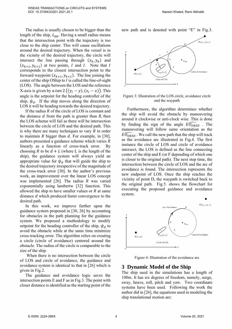
The guidance and avoidance logic saves the intersection points E and F as in Fig.3. The point with closer distance is identified as the starting point of the
new path and is denoted with point “E” in Fig.3.
Figure 3: Illustration of the LOS circle, avoidance circle and the waypath
Furthermore, the algorithm determines whether the ship will avoid the obstacle by maneuvering around it clockwise or anti-clock wise. This is done by finding the sign of the angle 𝐸𝑂𝑂𝐵𝑆𝐷
. The maneuvering will follow same orientation as the 𝐸𝑂𝑂𝐵𝑆𝐷
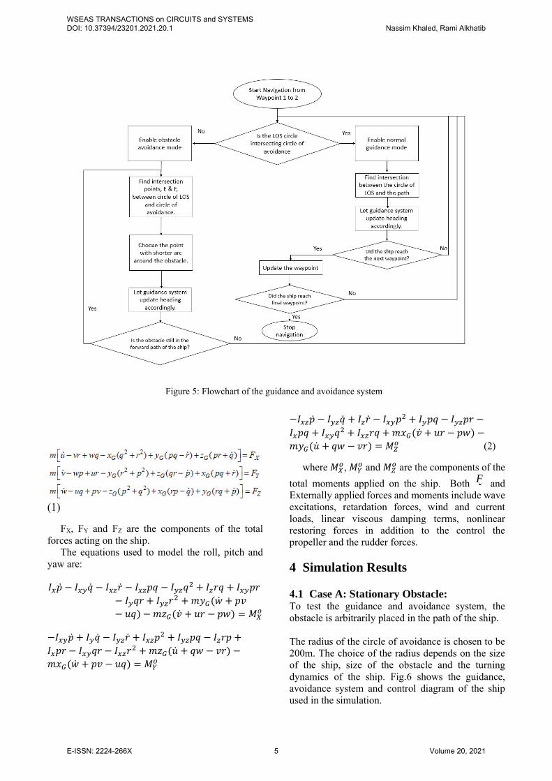
. We call the new path that the ship will track as the avoidance arc illustrated in Fig.4. The first instance the circle of LOS and circle of avoidance intersect, the LOS is defined as the line connecting center of the ship and E (or F depending of which one is closer to the original path). The next step time, the intersection between the circle of LOS and the arc of avoidance is found. The intersection represents the new endpoint of LOS. Once the ship reaches the vicinity of point D, the waypath is switched back to the original path. Fig.5. shows the flowchart for executing the proposed guidance and avoidance system.
Figure 4: Illustration of the avoidance arc
3 Dynamic Model of the Ship The ship used in the simulations has a length of 100m. It has six degrees of freedom, namely, surge, sway, heave, roll, pitch and yaw. Two coordinate systems have been used. Following the work the author did in [26], the equations used in modeling the ship translational motion are:
WSEAS TRANSACTIONS on CIRCUITS and SYSTEMS DOI: 10.37394/23201.2021.20.1 Nassim Khaled, Rami Alkhatib
E-ISSN: 2224-266X 4 Volume 20, 2021
(1)
FX, FY and FZ are the components of the total forces acting on the ship.
The equations used to model the roll, pitch and yaw are:
𝐼𝑥�� − 𝐼𝑥𝑦�� − 𝐼𝑥𝑧�� − 𝐼𝑥𝑧𝑝𝑞 − 𝐼𝑦𝑧𝑞2 + 𝐼𝑧𝑟𝑞 + 𝐼𝑥𝑦𝑝𝑟
− 𝐼𝑦𝑞𝑟 + 𝐼𝑦𝑧𝑟2 + 𝑚𝑦𝐺(�� + 𝑝𝑣
− 𝑢𝑞) − 𝑚𝑧𝐺(�� + 𝑢𝑟 − 𝑝𝑤) = 𝑀𝑋𝑜
−𝐼𝑥𝑦�� + 𝐼𝑦�� − 𝐼𝑦𝑧�� + 𝐼𝑥𝑧𝑝2 + 𝐼𝑦𝑧𝑝𝑞 − 𝐼𝑧𝑟𝑝 +
𝐼𝑥𝑝𝑟 − 𝐼𝑥𝑦𝑞𝑟 − 𝐼𝑥𝑧𝑟2 + 𝑚𝑧𝐺(�� + 𝑞𝑤 − 𝑣𝑟) −
𝑚𝑥𝐺(�� + 𝑝𝑣 − 𝑢𝑞) = 𝑀𝑌𝑜
−𝐼𝑥𝑧�� − 𝐼𝑦𝑧�� + 𝐼𝑧�� − 𝐼𝑥𝑦𝑝2 + 𝐼𝑦𝑝𝑞 − 𝐼𝑦𝑧𝑝𝑟 −
𝐼𝑥𝑝𝑞 + 𝐼𝑥𝑦𝑞2 + 𝐼𝑥𝑧𝑟𝑞 + 𝑚𝑥𝐺(�� + 𝑢𝑟 − 𝑝𝑤) −
𝑚𝑦𝐺(�� + 𝑞𝑤 − 𝑣𝑟) = 𝑀𝑍𝑜 (2)
where 𝑀𝑋𝑜, 𝑀𝑌
𝑜 and 𝑀𝑍𝑜 are the components of the
total moments applied on the ship. Both F and Externally applied forces and moments include wave excitations, retardation forces, wind and current loads, linear viscous damping terms, nonlinear restoring forces in addition to the control the propeller and the rudder forces. 4 Simulation Results
4.1 Case A: Stationary Obstacle: To test the guidance and avoidance system, the obstacle is arbitrarily placed in the path of the ship. The radius of the circle of avoidance is chosen to be 200m. The choice of the radius depends on the size of the ship, size of the obstacle and the turning dynamics of the ship. Fig.6 shows the guidance, avoidance system and control diagram of the ship used in the simulation.
Figure 5: Flowchart of the guidance and avoidance system
WSEAS TRANSACTIONS on CIRCUITS and SYSTEMS DOI: 10.37394/23201.2021.20.1 Nassim Khaled, Rami Alkhatib
E-ISSN: 2224-266X 5 Volume 20, 2021

To show the impact of the new logic, two simulations were conducted. The first one had the avoidance feature turned off. Then it was turned on in the second simulation. In both cases, the ship is navigating from A to B, then to C.
Fig.7 shows the position of the center of the ship in relation with the desired trajectory in the lower section.
The upper part of Fig.7 shows the way the guidance and avoidance algorithm react in the presence of an obstacle. The objective is to minimize the distance from the path, while minimizing the risk of impact to the obstacle.
A fictious circle is drawn around the obstacle of radius 200m. This represents a dangerous proximity to the obstacle. If the ship is within this zone, then
Figure 6: Guidance, avoidance and control block diagram for the ship
Figure 7: Guidance, avoidance and control block diagram for the ship
Figure 8: Heading and rudder angles of the ship during tracking
WSEAS TRANSACTIONS on CIRCUITS and SYSTEMS DOI: 10.37394/23201.2021.20.1 Nassim Khaled, Rami Alkhatib
E-ISSN: 2224-266X 6 Volume 20, 2021
there is a great risk of collision, depending on the size of the obstacle.
From the right plot of Fig. 8, one can notice how the ship successfully follows the top arc for the circle when it gets into the 200m proximity of the obstacle. At the point (600,200), the ship non-minimum phase behavior is clearly demonstrated. The ship is existing the avoidance mode. The guidance system resumes navigating under the assumption that the obstacle has been avoided.
Fig.8 shows that at 40 seconds, the guidance and avoidance system detects an obstacle in the path of the ship to the right of the figure. The rudder is turned to its maximum value in the negative direction to embrace a circular maneuver. Then at around 80 seconds, the guidance and avoidance system decides to switch back to follow the straight line trajectory.
In contract to the right part of Fig.7, the rudder was almost zero in the times between 40 to 80 seconds in Fig.7 left part where the avoidance logic was turned off.
It is worthwhile mentioning that in both plots of Fig. 8, there is a small offset between the ship position and the desired trajectory. This is a resultant of the external wave, wind and current forces. Despite the fact that the ship is headed (tilted) towards the path, the external forces prohibit the ship from converging to the path. The guidance system logic by default doesn’t account for such offset.
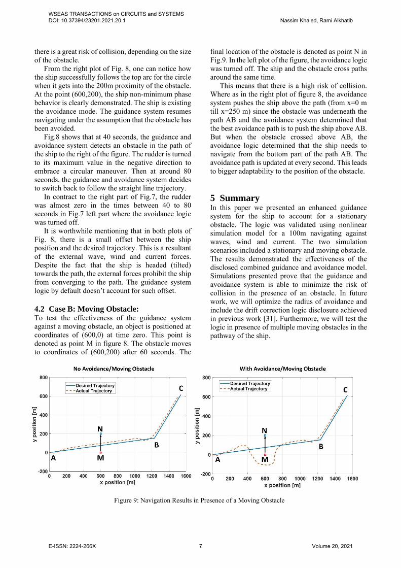
4.2 Case B: Moving Obstacle: To test the effectiveness of the guidance system against a moving obstacle, an object is positioned at coordinates of (600,0) at time zero. This point is denoted as point M in figure 8. The obstacle moves to coordinates of (600,200) after 60 seconds. The
final location of the obstacle is denoted as point N in Fig.9. In the left plot of the figure, the avoidance logic was turned off. The ship and the obstacle cross paths around the same time.
This means that there is a high risk of collision. Where as in the right plot of figure 8, the avoidance system pushes the ship above the path (from x=0 m till x=250 m) since the obstacle was underneath the path AB and the avoidance system determined that the best avoidance path is to push the ship above AB. But when the obstacle crossed above AB, the avoidance logic determined that the ship needs to navigate from the bottom part of the path AB. The avoidance path is updated at every second. This leads to bigger adaptability to the position of the obstacle.
5 Summary In this paper we presented an enhanced guidance system for the ship to account for a stationary obstacle. The logic was validated using nonlinear simulation model for a 100m navigating against waves, wind and current. The two simulation scenarios included a stationary and moving obstacle. The results demonstrated the effectiveness of the disclosed combined guidance and avoidance model. Simulations presented prove that the guidance and avoidance system is able to minimize the risk of collision in the presence of an obstacle. In future work, we will optimize the radius of avoidance and include the drift correction logic disclosure achieved in previous work [31]. Furthermore, we will test the logic in presence of multiple moving obstacles in the pathway of the ship.
Figure 9: Navigation Results in Presence of a Moving Obstacle
WSEAS TRANSACTIONS on CIRCUITS and SYSTEMS DOI: 10.37394/23201.2021.20.1 Nassim Khaled, Rami Alkhatib
E-ISSN: 2224-266X 7 Volume 20, 2021

References:
[1] Jing, W., Liu, C., Li, T. et al. Path Planning and Navigation of Oceanic Autonomous Sailboats and Vessels: A Survey. J. Ocean Univ. China 19, 609–621 (2020)., https://doi.org/10.1007/s11802-020-4144-7.
[2] "Breivik, M., & Fossen, T. I. (n.d.). Path following for marine surface vessels. Oceans ’04 MTS/IEEE Techno-Ocean ’04 (IEEE Cat. No.04CH37600). doi:10.1109/oceans.2004.1406507".
[3] "Oh, So-Ryeok, and Jing Sun. "Path following of underactuated marine surface vessels using line-of-sight based model predictive control." Ocean Engineering 37.2-3 (2010): 289-295.".
[4] E. Borhaug, A. Pavlov and K. Y. Pettersen, "Integral LOS control for path following of underactuated marine surface vessels in the presence of constant ocean currents," in 47th IEEE Conference on Decision and Control, Cancun, Mexico, 2008.
[5] "Li, Z., Sun, J., & Oh, S. (2009). Design, analysis and experimental validation of a robust nonlinear path following controller for marine surface vessels. Automatica, 45(7), 1649–1658. doi:10.1016/j.automatica.2009.03.010".
[6] "Zheng, Z., & Sun, L. (2016). Path following control for marine surface vessel with uncertainties and input saturation. Neurocomputing, 177, 158–167. doi:10.1016/j.neucom.2015.11.017".
[7] "Martinsen, A. B., & Lekkas, A. M. (2018). Straight-Path Following for Underactuated Marine Vessels using Deep Reinforcement Learning. IFAC-PapersOnLine, 51(29), 329–334. doi:10.1016/j.ifacol.2018.09.502".
[8] "Zhang, R.B.; Tang, P.; Su, Y.; Li, X.; Yang, G.; Shi, C. An adaptive obstacle avoidance algorithm for unmanned surface vehicle in complicated marine environments. IEEE CAA J. Autom. Sin. 2014, 1, 385–396.".
[9] "Guo, S., Zhang, X., Zheng, Y., & Du, A. Y. (2020). An Autonomous Path Planning Model for Unmanned Ships Based on Deep Reinforcement Learning. Sensors (Basel, Switzerland), 20(2), 426. https://doi.org/10.3390/s20020426".
[10] "Petres, C.; Romero-Ramirez, M.A.; Plumet, F. Reactive path planning for autonomous sailboat. In Proceedings of the 2011 IEEE International Conference on Advanced
Robotics (ICAR), Tallinn, Estonia, 20–23 June 2011; pp. 112–117.".
[11] "Xu, H., & Guedes Soares, C. (2016). Vector field path following for surface marine vessel and parameter identification based on LS-SVM. Ocean Engineering, 113, 151–161. doi:10.1016/j.oceaneng.2015.12.037".
[12] "Shen, H.Q.; Hashimoto, H.; Matsuda, A.; Taniguchi, Y.; Terada, D.; Guo, C. Automatic collision avoidance of multiple ships based on deep Q-learning. Appl. Ocean Res. 2019, 86, 268–288.".
[13] M. D. Pedersen and T. I. Fossen, "Marine Vessel Path Planning & Guidance Using Potential Flow," in 9th IFAC Conference on Manoeuvring and Control of Marine Craft, The International Federation of Automatic Control, Arenzano, Italy, 19-21, 2012.
[14] "Yang, J.; Liu, L.; Zhang, Q.; Liu, C. Research on Autonomous Navigation Control of Unmanned Ship Based on Unity3D. In Proceedings of the 2019 IEEE International Conference on Control, Automation and Robotics (ICCAR), Beijing, China, 19–22 April 2019; pp.".
[15] Mankabady, S. The International Maritime Organization, Volume 1: International Shipping Rules; Croom Helm Ltd.: London, UK, 1986; p. 450..
[16] "Tam, C., & Bucknall, R. (2013). Cooperative path planning algorithm for marine surface vessels. Ocean Engineering, 57, 25–33. doi:10.1016/j.oceaneng.2012.09.003".
[17] "J.-H. Ahn, K.-P. Rhee, and Y.-J. You, “A study on the collision avoidance of a ship using neural networks and fuzzy logic,” Applied Ocean Research, vol. 37, pp. 162–173, 2012.".
[18] "R. Szlapczynski and J. Szlapczynska, “An analysis of domain-based ship collision risk parameters,” Ocean Engineering, vol. 126, pp. 47–56, 2016.".
[19] "Jinxin Li, Hongbo Wang, Wei Zhao, Yuanyuan Xue, "Ship’s Trajectory Planning Based on Improved Multiobjective Algorithm for Collision Avoidance", Journal of Advanced Transportation, vol. 2019, Article ID 4068783, 12 pages, 2019.," https://doi.org/10.1155/2019/4068783.
[20] "Xie, S.; Chu, X.; Zheng, M.; Liu, C. Ship predictive collision avoidance method based on an improved beetle antennae search algorithm. Ocean Eng. 2019, 192, 106542".
WSEAS TRANSACTIONS on CIRCUITS and SYSTEMS DOI: 10.37394/23201.2021.20.1 Nassim Khaled, Rami Alkhatib
E-ISSN: 2224-266X 8 Volume 20, 2021

[21] Zhao, Y., Li, W., & Shi, P. (2016). A real-time collision avoidance learning system for Unmanned Surface Vessels. Neurocomputing, 182, 255–266. doi:10.1016/j.neucom.2015.12.028.
[22] Korte, H., Koeckritz, O., & Kurowski, M. (2015). Precise Maneuver Planning for Berth-to-Berth Navigation of Modern Ships. at - Automatisierungstechnik, 63, 368 - 379..
[23] Naeem, W., Irwin, G. W., & Yang, A. (2012). COLREGs-based collision avoidance strategies for unmanned surface vehicles. Mechatronics, 22(6), 669–678. doi:10.1016/j.mechatronics.2011.09.012.
[24] Abdelaal, M., Fränzle, M., & Hahn, A. (2018). Nonlinear Model Predictive Control for trajectory tracking and collision avoidance of underactuated vessels with disturbances. Ocean Engineering, 160, 168–180. doi:10.1016/j.oceaneng.2018.04.026.
[25] F. Thompson and R. Galeazzib, "Robust mission planning for Autonomous Marine Vehicle fleets," Robotics and Autonomous Systems, vol. 124, no. 103404, 2020.
[26] Khaled, N., & Chalhoub, N. G. (2013). A self-tuning guidance and control system for marine surface vessels. Nonlinear Dynamics, 73(1-2), 897–906. doi:10.1007/s11071-013-0840-9".
[27] Khaled N., Chalhoub N.G. (2009) A Dynamic Model and a Robust Controller for a Fully Actuated Marine Surface Vessel. In: Ibrahim R.A., Babitsky V.I., Okuma M. (eds) Vibro-Impact Dynamics of Ocean Systems and Related Problems.," Lecture Notes in Applied and Computational Mechanics, vol 44. Springer, Berlin, Heidelberg.
[28] Chalhoub, N. G., & Khaled, N. (2012). Integrated controller-observer system for marine surface vessels. Journal of Vibration and Control, 20(3), 381–394. doi:10.1177/1077546312461026.
[29] Fossen, T. I., 2002, Marine Control Systems: Guidance, Navigation and Control of Ships, Rigs and Underwater Vehicles, Marine Cybernetics AS, Trondheim, ISBN 82-92356-00-2.
[30] Moreira, L., Fossen, T. I. and Guedes Soares, C., 2007, “Path Following Control System for a Tanker Ship Model,” Ocean Engineering OE-34:2074–2085.
[31] Nabil G Chalhoub and Nassim Khaled, Guidance and Control System For Under-
Actuated Marine Surface Ships And Other Autonomous Platforms, US patent 9213336, 2015.
[32] https://www.mathworks.com/help/symbolic/lambertw.html
Author Contributions:
Nassim Khaled carried out the simulation and testing of the proposed algorithms Rami Alkharib carried the derivation and verification of the mathematical equations and experimentations. Acknowledgement:
The authors wish to acknowledge the support from Prince Mohammad Bin Fahd University. Creative Commons Attribution License 4.0 (Attribution 4.0 International, CC BY 4.0)
This article is published under the terms of the Creative Commons Attribution License 4.0 https://creativecommons.org/licenses/by/4.0/deed.en_US
WSEAS TRANSACTIONS on CIRCUITS and SYSTEMS DOI: 10.37394/23201.2021.20.1 Nassim Khaled, Rami Alkhatib
E-ISSN: 2224-266X 9 Volume 20, 2021