nord lead a1 english user manual v1.3x edition f.pdf
TRANSCRIPT
User ManualNord Lead A1
Nord Lead A1ROS Version 1.3x
Part No. 50425 Copyright Clavia DMI ABPrint Edition: F

CAUTION - ATTENTIONRISK OF ELECTRIC SHOCK
DO NOT OPENRISQUE DE SHOCK ELECTRIQUE
NE PAS OUVRIR
CAUTION: TO REDUCE THE RISK OF ELECTRIC SHOCK DO NOT REMOVE COVER (OR BACK).
NO USER SERVICEABLE PARTS INSIDE.REFER SERVICING TO QUALIFIED PERSONNEL.
ATTENTION:POUR EVITER LES RISQUES DE CHOC ELECTRIQUE, NE PAS ENLEVER LE COUVERCLE.
AUCUN ENTRETIEN DE PIECES INTERIEURES PAR L´USAGER. CONFIER L´ENTRETIEN AU PERSONNEL QUALIFE.
AVIS: POUR EVITER LES RISQUES D´INCIDENTE OU D´ELECTROCUTION, N´EXPOSEZ PAS CET ARTICLE A LA PLUIE OU L´HUMIDITET.
1) Read these instructions.
2) Keep these instructions.
3) Heed all warnings.
4) Follow all instructions.
5) Do not use this apparatus near water.
6) Clean only with dry cloth.
7) Do not block any ventilation openings. Install in accordance with the manufacturer’s instructions.
8) Do not install near any heat sources such as radiators, heat registers, stoves, or other apparatus (including amplifiers) that produce heat.
9) Do not defeat the safety purpose of the polarized or grounding-type plug. A polarized plug has two blades with one wider than the other. A grounding type plug has two blades and a third grounding prong. The wide blade or the third prong are provided for your safety. If the provided plug does not fit into your outlet, consult an electrician for replacement of the obsolete outlet.
10) Protect the power cord from being walked on or pinched particularly at plugs, convenience receptacles, and the point where they exit from the apparatus.
11) Only use attachments/accessories specified by the manu-facturer.
12) Use only with the cart, stand, tripod, bracket, or table specified by the manufacturer, or sold with the apparatus. When a cart is used, use caution when moving the cart/apparatus combination to avoid injury from tip-over.
13) Unplug this apparatus during lightning storms or when unused for long periods of time.
14) Refer all servicing to qualified service personnel. Servicing is required when the apparatus has been damaged in any way, such as power-supply cord or plug is damaged, liquid has been spilled or objects have fallen into the apparatus, the apparatus has been exposed to rain or moisture, does not operate nor-mally, or has been dropped.
The lightning flash with the arrowhead symbol within an equilateral triangle is intended to alert the user to the presence of uninsulated voltage within the products en-closure that may be of sufficient magnitude to constitute a risk of electric shock to persons.
Le symbole éclair avec le point de flèche à l´intérieur d´un triangle équilatéral est utilisé pour alerter l´utilisateur de la presence à l´intérieur du coffret de ”voltage dangereux” non isolé d´ampleur suffisante pour constituer un risque d`éléctrocution.
The exclamation mark within an equilateral triangle is intended to alert the user to the presence of important operating and maintenance (servicing) instructions in the literature accompanying the product.
Le point d´exclamation à l´intérieur d´un triangle équilatéral est employé pour alerter l´utilisateur de la présence d´instructions importantes pour le fonctionnement et l´entretien (service) dans le livret d´instructions accompagnant l´appareil.
Instructions pertaining to a risk of fire, electric shock or injury to persons.
IMPORTANT SAFETY INSTRUCTIONSSAVE THESE INSTRUCTIONS
Trademarks: The Nord logo is a trademark of Clavia DMI AB. All other trademarks mentioned in this publication are the properties of their respective holders.
Specifications and appearances are subject to change without notice. Copyright © Clavia DMI AB
No naked flame sources, such as lighted candles, should be placed on the apparatus;
Do not use the apparatus in tropical climates.
WARNING: To reduce the risk of fire or electric shock, do not expose this apparatus to rain or moisture.
The apparatus shall not be exposed to dripping or splashing and that no objects filled with liquids, such as vases, shall be placed on the apparatus.
The maims plug is used as the disconnect device and shall remain readily operable.
Il convient de ne pas placer sur l´appareil de sources de flammes nues, telles que des bougies allumées;
L´appareil n’est pas destiné á étre utilisé sous un climat tropical.
L´appareil ne doit pas étre exposé á des égouttements d´eau ou des éclaboussures et de plus qu´aucun objet rempli de liquide tel que des vases ne doit étre placé sur l´appareil.
Lorsque la prise du résau d’alimentation est utilisée comme dispositif de déconnexion, ce dispositif doit demeuré aisément accessible.
Warning - When using electric products, basic precautions should always be followed, including the following:
Additional Safety Information

| 3
1Introduction
The Lead For Speed . . . . . . . . . . . . . . . . . . 52 models - keyboard and tabletop . . . . . . 5
2Overview
The Panel . . . . . . . . . . . . . . . . . . . . . . . . . . 6Oscillator, Filter & Amp Env . . . . . . . . . . . 6Modulation . . . . . . . . . . . . . . . . . . . . . . . . 6Effects and Output . . . . . . . . . . . . . . . . . . 6Voice Mode . . . . . . . . . . . . . . . . . . . . . . . 6Pitch Stick . . . . . . . . . . . . . . . . . . . . . . . . 6Mod Wheel . . . . . . . . . . . . . . . . . . . . . . . 6Arpeggiator . . . . . . . . . . . . . . . . . . . . . . . 6Program and Performance . . . . . . . . . . . 6Morph . . . . . . . . . . . . . . . . . . . . . . . . . . . 6
Editing . . . . . . . . . . . . . . . . . . . . . . . . . . . . 7Buttons . . . . . . . . . . . . . . . . . . . . . . . . . . . 7On/Off buttons . . . . . . . . . . . . . . . . . . . . 7Selector buttons . . . . . . . . . . . . . . . . . . . 7Shift button . . . . . . . . . . . . . . . . . . . . . . . 7Master Clock (Mst Clk) . . . . . . . . . . . . . . 7
Knobs & dials . . . . . . . . . . . . . . . . . . . . . . . 7Knobs . . . . . . . . . . . . . . . . . . . . . . . . . . . 7Knobs with Shift features . . . . . . . . . . . . 7Dials . . . . . . . . . . . . . . . . . . . . . . . . . . . . 7Master Level . . . . . . . . . . . . . . . . . . . . . . 7
Rear Panel . . . . . . . . . . . . . . . . . . . . . . . . . 8Audio Connections . . . . . . . . . . . . . . . . . . . . 8Headphones . . . . . . . . . . . . . . . . . . . . . . 81, 2, 3 & 4 Outputs . . . . . . . . . . . . . . . . . . 8General guide on audio connections . . . . 8
MIDI Connections . . . . . . . . . . . . . . . . . . . . 8MIDI OUT . . . . . . . . . . . . . . . . . . . . . . . . . 8MIDI IN . . . . . . . . . . . . . . . . . . . . . . . . . . . 8
USB Connection . . . . . . . . . . . . . . . . . . . . . 8USB MIDI . . . . . . . . . . . . . . . . . . . . . . . . . 8
Pedal Connections . . . . . . . . . . . . . . . . . . . . 8Sustain pedal . . . . . . . . . . . . . . . . . . . . . . 8Control pedal . . . . . . . . . . . . . . . . . . . . . . 8
3Getting Started
Slots . . . . . . . . . . . . . . . . . . . . . . . . . . . . 9Selecting a Program . . . . . . . . . . . . . . . . 9Editing a Program . . . . . . . . . . . . . . . . . . 9Storing a Program . . . . . . . . . . . . . . . . . . 9Layering Programs . . . . . . . . . . . . . . . . . . 9Soloing a Slot . . . . . . . . . . . . . . . . . . . . . . 9Multi Focus . . . . . . . . . . . . . . . . . . . . . . . 9Creating a Split . . . . . . . . . . . . . . . . . . . 10Setting the Split point . . . . . . . . . . . . . . . 10Working with Performances . . . . . . . . . . 10Selecting Performances . . . . . . . . . . . . . 10Editing a Performance . . . . . . . . . . . . . . 10Storing a Performance . . . . . . . . . . . . . . 10Storing Programs as a Performance . . . 10Setting up a Morph . . . . . . . . . . . . . . . . 10
4Slots and Memory
General Overview . . . . . . . . . . . . . . . . . . . 11Slot Handling . . . . . . . . . . . . . . . . . . . . . 11Split . . . . . . . . . . . . . . . . . . . . . . . . . . . . 11Solo . . . . . . . . . . . . . . . . . . . . . . . . . . . . 11Multi Focus . . . . . . . . . . . . . . . . . . . . . . 11Program Handling . . . . . . . . . . . . . . . . . 12Programs . . . . . . . . . . . . . . . . . . . . . . . . 12Performances . . . . . . . . . . . . . . . . . . . . 12Performance Mode . . . . . . . . . . . . . . . . 12Loading . . . . . . . . . . . . . . . . . . . . . . . . . 12Storing . . . . . . . . . . . . . . . . . . . . . . . . . . 12Copying Slots to a Performance . . . . . . 12Copying a Performance to Program . . . 12
5Morph
Morphing . . . . . . . . . . . . . . . . . . . . . . . . . 13The Morphs . . . . . . . . . . . . . . . . . . . . . . . 13Wheel/Control Pedal . . . . . . . . . . . . . . . 13Velocity . . . . . . . . . . . . . . . . . . . . . . . . . 13Assign a Morph source to a parameter . 13Morph parameters . . . . . . . . . . . . . . . . . 13
Editing Morphs . . . . . . . . . . . . . . . . . . . . 14Morph Programming Latch . . . . . . . . . . . . 14
6Mutator, Randomize & Like
Mutator . . . . . . . . . . . . . . . . . . . . . . . . . . 15Executing the Mutation . . . . . . . . . . . . . 15
Randomize . . . . . . . . . . . . . . . . . . . . . . . . 15Mutate Morph . . . . . . . . . . . . . . . . . . . . . . 15Like . . . . . . . . . . . . . . . . . . . . . . . . . . . . . 16Program Likes . . . . . . . . . . . . . . . . . . . . 16Performance Likes . . . . . . . . . . . . . . . . . 16Select a Like to Store . . . . . . . . . . . . . . 16
7Panel Reference
Master Level . . . . . . . . . . . . . . . . . . . . . . 17MIDI LED . . . . . . . . . . . . . . . . . . . . . . . . 17
Morph . . . . . . . . . . . . . . . . . . . . . . . . . . . 17Program/Value Dial . . . . . . . . . . . . . . . . . 17LED Display . . . . . . . . . . . . . . . . . . . . . . 17
Performance Mode/Execute . . . . . . . . . . . . 17Store . . . . . . . . . . . . . . . . . . . . . . . . . . . 17
Copy/Monitor . . . . . . . . . . . . . . . . . . . . . . 17Paste . . . . . . . . . . . . . . . . . . . . . . . . . . . 17
Slot A - D . . . . . . . . . . . . . . . . . . . . . . . . 18Deactivate a Slot . . . . . . . . . . . . . . . . . . 18Panel Focus . . . . . . . . . . . . . . . . . . . . . . 18Multi Focus . . . . . . . . . . . . . . . . . . . . . . 18Soloing a Slot . . . . . . . . . . . . . . . . . . . . . 18Incoming MIDI . . . . . . . . . . . . . . . . . . . . 18System - MIDI - Sound . . . . . . . . . . . . . 18Master Clock . . . . . . . . . . . . . . . . . . . . . 18
Octave Shift . . . . . . . . . . . . . . . . . . . . . . . 18Keyboard Octave Shift . . . . . . . . . . . . . . 18Split . . . . . . . . . . . . . . . . . . . . . . . . . . . . 18Setting the Split point . . . . . . . . . . . . . . . 18
Hold . . . . . . . . . . . . . . . . . . . . . . . . . . . . 18Hold Enable . . . . . . . . . . . . . . . . . . . . . . 18
Shift/Exit . . . . . . . . . . . . . . . . . . . . . . . . . 18Pitch Stick . . . . . . . . . . . . . . . . . . . . . . . . 18Modulation Wheel . . . . . . . . . . . . . . . . . 19
Arpeggiator . . . . . . . . . . . . . . . . . . . . . . . 19Arpeggio Run . . . . . . . . . . . . . . . . . . . . . 19Arpeggio Rate . . . . . . . . . . . . . . . . . . . . 19Arpeggio Mst Clk . . . . . . . . . . . . . . . . . . 19Arpeggio Range . . . . . . . . . . . . . . . . . . . 19Arpeggio Directions . . . . . . . . . . . . . . . . 19Panic . . . . . . . . . . . . . . . . . . . . . . . . . . . 19
Voice Mode . . . . . . . . . . . . . . . . . . . . . . . 19Unison . . . . . . . . . . . . . . . . . . . . . . . . . . 19Mono . . . . . . . . . . . . . . . . . . . . . . . . . . 19Legato . . . . . . . . . . . . . . . . . . . . . . . . . . 19Glide . . . . . . . . . . . . . . . . . . . . . . . . . . . 19Multi Focus . . . . . . . . . . . . . . . . . . . . . . 19Bend Range . . . . . . . . . . . . . . . . . . . . . 19
Vibrato . . . . . . . . . . . . . . . . . . . . . . . . . . 19Init Sound . . . . . . . . . . . . . . . . . . . . . . . 19
Low Frequency Oscillator (LFO/ENV) . . . . . 20Rate/Time . . . . . . . . . . . . . . . . . . . . . . . 20LFO Master Clock (Mst Clk) . . . . . . . . . 20LFO Waveform Selector . . . . . . . . . . . . . 20Envelope . . . . . . . . . . . . . . . . . . . . . . . . 20LFO Modulation Polarities . . . . . . . . . . . 20
Modulation Envelope . . . . . . . . . . . . . . . . 20Attack . . . . . . . . . . . . . . . . . . . . . . . . . . 20Decay . . . . . . . . . . . . . . . . . . . . . . . . . . 20Release . . . . . . . . . . . . . . . . . . . . . . . . . 20Inverted Envelope . . . . . . . . . . . . . . . . . 21Env Vel . . . . . . . . . . . . . . . . . . . . . . . . . . 21
Oscillators . . . . . . . . . . . . . . . . . . . . . . . . 21Panel Analog Waveforms . . . . . . . . . . . 21Extended Analog Waveforms . . . . . . . . . 21Fixed Pulse Waveforms . . . . . . . . . . . . . 21Drawbar Organ Waveforms . . . . . . . . . . 21Bells and Tines . . . . . . . . . . . . . . . . . . . 21Digital . . . . . . . . . . . . . . . . . . . . . . . . . . . 22Electric . . . . . . . . . . . . . . . . . . . . . . . . . . 22Formants . . . . . . . . . . . . . . . . . . . . . . . . 22
Oscillator Configuration . . . . . . . . . . . . . . . 22Single Oscillator Configurations . . . . . . . 22Pitch . . . . . . . . . . . . . . . . . . . . . . . . . . . 22Shape . . . . . . . . . . . . . . . . . . . . . . . . . . 22Sync . . . . . . . . . . . . . . . . . . . . . . . . . . . 22Dual Oscillator Configurations . . . . . . . . 22Detune . . . . . . . . . . . . . . . . . . . . . . . . . 22Sine, Tri, Saw and Pulse Mix . . . . . . . . . 23Modulation Configurations . . . . . . . . . . . 23FM (Frequency Modulation) . . . . . . . . . . 23AM (Amplitude Modulation) . . . . . . . . . . 23
Amp Envelope . . . . . . . . . . . . . . . . . . . . . 23Attack . . . . . . . . . . . . . . . . . . . . . . . . . . 23Decay . . . . . . . . . . . . . . . . . . . . . . . . . . 23Release . . . . . . . . . . . . . . . . . . . . . . . . . 23Env Vel . . . . . . . . . . . . . . . . . . . . . . . . . . 23
Filter . . . . . . . . . . . . . . . . . . . . . . . . . . . . 24Filter Frequency (Freq) . . . . . . . . . . . . . . 24Filter Resonance . . . . . . . . . . . . . . . . . . 24LFO Amount . . . . . . . . . . . . . . . . . . . . . 24Modulation Envelope Amount . . . . . . . . 24Keyboard Tracking (KB Track) . . . . . . . . 24Drive . . . . . . . . . . . . . . . . . . . . . . . . . . . 24Filter Type . . . . . . . . . . . . . . . . . . . . . . . 24
Nord Lead A1 User Manual
4 | NordLeada1UserMaNUaLv1.3x
LP 12, 24 . . . . . . . . . . . . . . . . . . . . . . . . 24LP M . . . . . . . . . . . . . . . . . . . . . . . . . . . 24LP TB . . . . . . . . . . . . . . . . . . . . . . . . . . . 25BP . . . . . . . . . . . . . . . . . . . . . . . . . . . . . 25HP . . . . . . . . . . . . . . . . . . . . . . . . . . . . . 25
FX . . . . . . . . . . . . . . . . . . . . . . . . . . . . . . 25Flanger . . . . . . . . . . . . . . . . . . . . . . . . . . 25Phaser . . . . . . . . . . . . . . . . . . . . . . . . . . 25RM . . . . . . . . . . . . . . . . . . . . . . . . . . . . . 25Chorus . . . . . . . . . . . . . . . . . . . . . . . . . . 25Ensemble . . . . . . . . . . . . . . . . . . . . . . . . 25Drive . . . . . . . . . . . . . . . . . . . . . . . . . . . 25Mutate Sound . . . . . . . . . . . . . . . . . . . . 25
Delay . . . . . . . . . . . . . . . . . . . . . . . . . . . 25Tempo . . . . . . . . . . . . . . . . . . . . . . . . . . 25Tap Tempo . . . . . . . . . . . . . . . . . . . . . . . 26Mst Clk . . . . . . . . . . . . . . . . . . . . . . . . . 26Feedback . . . . . . . . . . . . . . . . . . . . . . . . 26Ping Pong . . . . . . . . . . . . . . . . . . . . . . . 26Sound Menu Delay Mode . . . . . . . . . . . 26On/Off . . . . . . . . . . . . . . . . . . . . . . . . . . 26Randomize Sound . . . . . . . . . . . . . . . . . 26
Output . . . . . . . . . . . . . . . . . . . . . . . . . . . 26Level . . . . . . . . . . . . . . . . . . . . . . . . . . . 26Pan . . . . . . . . . . . . . . . . . . . . . . . . . . . . 26
Reverb . . . . . . . . . . . . . . . . . . . . . . . . . . . 26Dry/Wet . . . . . . . . . . . . . . . . . . . . . . . . . 26Reverb Select . . . . . . . . . . . . . . . . . . . . 26On/Off . . . . . . . . . . . . . . . . . . . . . . . . . . 26Like . . . . . . . . . . . . . . . . . . . . . . . . . . . . 26
Note Trig (Nord Lead A1R) . . . . . . . . . . . . 26
8Master Clock
Master Clock . . . . . . . . . . . . . . . . . . . . . . . 27External Sync . . . . . . . . . . . . . . . . . . . . . 27
Arpeggio with Mst Clk . . . . . . . . . . . . . . . . 27Synced Delay repeats . . . . . . . . . . . . . . 28Sync the LFO . . . . . . . . . . . . . . . . . . . . . 28Across the Slots . . . . . . . . . . . . . . . . . . . 28Sound Menu Kbd Sync . . . . . . . . . . . . . 28
9Nord Sound Manager
System requirements . . . . . . . . . . . . . . . 29
10The Menus
System Menu . . . . . . . . . . . . . . . . . . . . . . 301 - Memory Protect . . . . . . . . . . . . . . . . 302 - Transpose . . . . . . . . . . . . . . . . . . . . . 303 - Fine Tune . . . . . . . . . . . . . . . . . . . . . 304 - Sustain Pedal Polarity . . . . . . . . . . . . 305 - Wheel Mode . . . . . . . . . . . . . . . . . . . 306 - Ctrl Pedal Mode . . . . . . . . . . . . . . . . 307 - Ctrl Pedal Type . . . . . . . . . . . . . . . . . 308 - Ctrl Pedal Gain . . . . . . . . . . . . . . . . . 309 - Mutator Protect . . . . . . . . . . . . . . . . 30A B C D - Slot Output Routing . . . . . . . . 30
MIDI Menu . . . . . . . . . . . . . . . . . . . . . . . . 31G - Global MIDI Channel . . . . . . . . . . . . 31A, B, B, D - Slot MIDI Channel . . . . . . . . 31t - Soft Thru MIDI Channel . . . . . . . . . . . 311 - Local Control . . . . . . . . . . . . . . . . . . 312 - Control Change (CC) Mode . . . . . . . 313 - Program Change Mode . . . . . . . . . . 314 - Pitch Bend Mode . . . . . . . . . . . . . . . 315 - Send CC . . . . . . . . . . . . . . . . . . . . . 316 - Dump One . . . . . . . . . . . . . . . . . . . . 317 - Dump Program Bank . . . . . . . . . . . . 31
Sound Menu . . . . . . . . . . . . . . . . . . . . . . 311 - Mst Clk Kbd Sync . . . . . . . . . . . . . . . 312 - Delay Mode . . . . . . . . . . . . . . . . . . . 313 - Vibrato Rate . . . . . . . . . . . . . . . . . . . 314 - Vibrato Amount . . . . . . . . . . . . . . . . . 31
11MIDI
Nord Lead A1 MIDI operation . . . . . . . . . . . 32MIDI Settings . . . . . . . . . . . . . . . . . . . . . 32Global MIDI Channel . . . . . . . . . . . . . . . 32Slot MIDI Channels . . . . . . . . . . . . . . . . 32
Sequencing: Global MIDI Channel . . . . . . . 32Recording parameter changes . . . . . . . 32
Sequencing: Slot MIDI Channels . . . . . . . . 32Control Slots with another keyboard . . . . . 33Message types . . . . . . . . . . . . . . . . . . . . . 33Program Changes and Bank Select . . . . 33Control Change messages . . . . . . . . . . 33Pedal Control Change . . . . . . . . . . . . . . 33Volume . . . . . . . . . . . . . . . . . . . . . . . . . . 33Pan CC . . . . . . . . . . . . . . . . . . . . . . . . . 33MIDI Local . . . . . . . . . . . . . . . . . . . . . . . 33MIDI Thru . . . . . . . . . . . . . . . . . . . . . . . . 33MIDI Clock . . . . . . . . . . . . . . . . . . . . . . . 33USB MIDI . . . . . . . . . . . . . . . . . . . . . . . . 33Panic . . . . . . . . . . . . . . . . . . . . . . . . . . . 33
MIDI Dumps . . . . . . . . . . . . . . . . . . . . . . . 33Transmit settings . . . . . . . . . . . . . . . . . . 33Receive Programs or Banks . . . . . . . . . 33
MIDI Controller list . . . . . . . . . . . . . . . . . . 34MIDI Implementation Chart . . . . . . . . . . 35
12Appendix
Specifications . . . . . . . . . . . . . . . . . . . . . . 36Display Messages . . . . . . . . . . . . . . . . . . . 37
13Index
Index . . . . . . . . . . . . . . . . . . . . . . . . . . . . 38

Chapter1IntroduCtIon | 5
The Lead For SpeedProducing stand-out sounds for live or for the studio, the Lead A1 is ideal for all musical genres. Thanks to its carefully thought-out user interface, the Lead A1 encourages experimentation, allows for far speedier programming than would otherwise be possible, and ulti-mately delivers sensational sonic results.
Our best-ever analog modeling …
At the heart of the Lead A1 is our new analog modeling engine. Taking our virtual analog synthesis to a new level, this modeling recreates a total analog signal path with uncanny realism, and is capable of im-mense sonic variety. With a 26-voice polyphony and four simultaneous synthesizer parts, the Lead A1 is a true synthesizer powerhouse that goes far beyond the current trend for limited capability analog reissues.
... combined with our most intuitive interface
Fundamental to the design of the Lead A1 is a brand new simple yet sophisticated front panel interface. The Lead A1 allows easy patch creation and experimentation thanks to a new and unique oscillator section, pre-programmed modulation matrix, and simplified ADR/ASR envelopes.
Like-button
The Like function is a unique feature that is invalu-able during the patch creation process. “Like” up to 50 versions of a patch as you design it, scroll between them to choose your favorite to save to actual memory, or go back to an earlier version to edit in a different way.
Sound Manager
The Lead A1 is compatible with the Nord Sound Manager application for OS X and Windows. Sound Manager is a dedicated librarian that allows for easy reorganizing, back-up and transfer of programs.
Hardware
Like all Nord keyboards the Lead A1 is handmade in Nord’s Stockholm factory with incredible attention to detail and quality control. The Fatar® 49-key keybed (keyboard version only), all-metal chassis, tactile knobs, and unfaltering emphasis on quality complete a synthesizer designed to last a lifetime.
2 models - keyboard and tabletopThe Nord Lead A1 comes either as a 49-key velocity sensitive key-board with a modulation wheel and wooden pitch stick, or as a table-top unit - the Nord Lead A1R. It has 4 line level outputs, 1 headphone output, MIDI IN & OUT, a USB port with MIDI capabilities and inputs for a sustain pedal and a control pedal.
1Introduction

6 | Nord Lead a1 User MaNUaL v1.3x
The PanelWe will familiarize ourselves briefly with the controls on the panel here.
1 Oscillator, Filter & Amp EnvThe Lead A1’s new Oscillator section generates 47 different waveforms from classic analog to digital harmonic and inharmonic waves, whilst unique Oscillator Configuration Shortcuts make programming more immediate than ever. Start with a single Oscillator waveform and select an Oscillator Configuration Shortcut - Pitch, Detune, Shape, Sync, Sub Mix, FM, AM or Noise - and use the Adjust knob to adjust the settings of the configuration. The Lead A1’s filter section features classic 12 and 24 dB Low Pass, a High Pass and a Band Pass filter, together with stunning emulations of the diode and ladder filters from the legendary Mini and the TB-303 synthesizers. The Lead A1’s modeling of these filters capture the true character and response of the originals, allowing supremely flexible and precise sound design.
2 ModulationThe Lead A1 features an LFO with a choice of waveforms and a three-stage ADR/ASR Modulation Envelope. The LFO rate can be sync’d to the Lead A1’s master clock. The Mod Envelope can be inverted. Thanks to the intuitive design of the front panel it is very easy to see what modulations have been applied and to design incredible sounding patches.
3 Effects and OutputThe Lead A1’s effects section features two stunning brand new analog models of an Ensemble and Chorus, modeled from specific vintage synths and adding classic warmth and analog feel. Alongside these, choose from great-sounding Ring Modulation, Phaser, Flanger, or Drive per slot, and in addition a separate Delay and Reverb for each slot.
4 Voice ModeThe Voice Mode Unison parameter can be used to stack several voices on top of each other to create a fatter sound. Mono and Legato are two monophonic behaviors.
5 Pitch Stick The Pitch Stick is used to bend the notes, with different ranges for each program if you like. There is no dead centre in the middle of the throw. This allows you to use the Pitch Stick for natural vibrato, pretty much like a guitarist do. The effect on pitch is logarithmic, that is, the further you move the Pitch Stick away from the centre position, the more drastic the effect.
6 Mod WheelUse the Mod Wheel to add vibrato and act as a Morph controller to change parameters in real time.
M Physical Pitch Bend and Mod Wheel controls are not available on the Nord Lead A1R but it will have an identical performance as the keyboard model when it responds to incoming MIDI Pitch Bend and Mod Wheel messages.
7 ArpeggiatorThe Lead A1 features four separate Arpeggiators with Up/Down and Random modes and a 4-octave range. Arpeggios can be synchronized to the Lead A1’s master clock.
8 Program and PerformanceThe Program Dial and its associated LED display is used to load indi-vidual programs or performances that can consist of up to 4 individual slots, each with its own sound.
9 MorphA classic Nord feature,the Morph function allows you to control multiple parameters of the Lead A1 simultaneously via Mod Wheel, Velocity or pedal. Morph is exceptionally easy to set-up and use - just hold the Morph button and adjust any desired knob.
2 Overview
9 7
54 1 32
8
6
Chapter 2 overview | 7
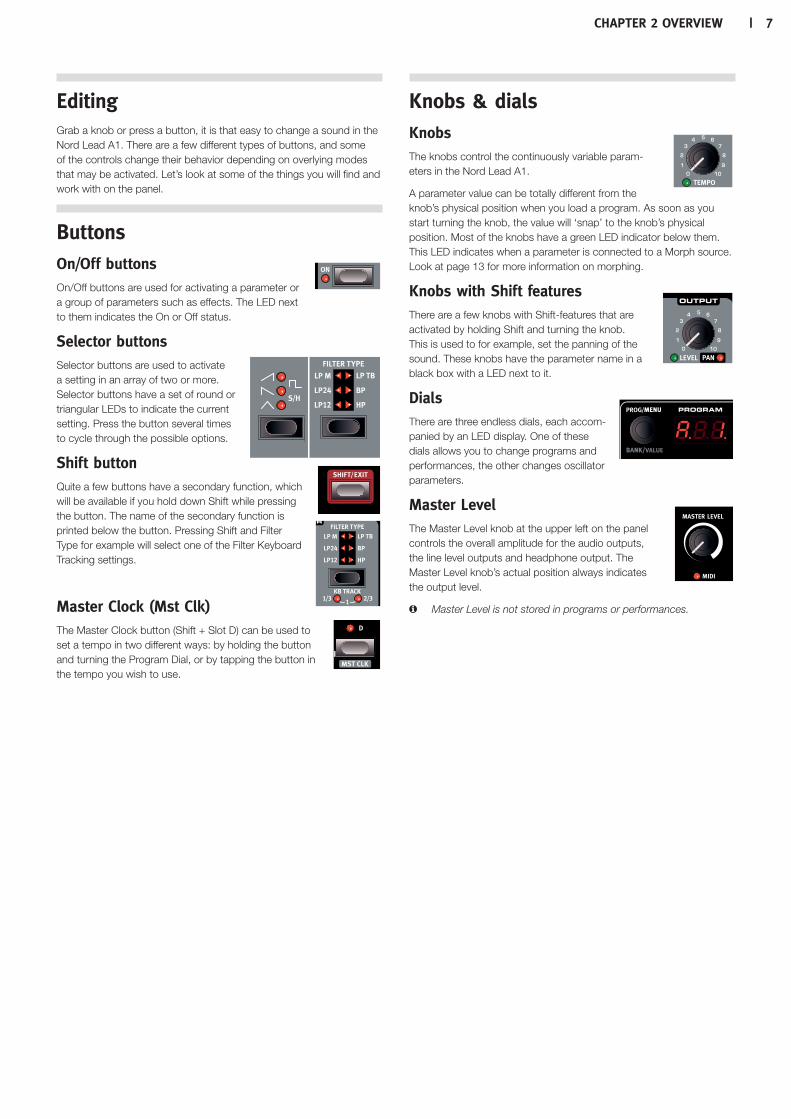
EditingGrab a knob or press a button, it is that easy to change a sound in the Nord Lead A1. There are a few different types of buttons, and some of the controls change their behavior depending on overlying modes that may be activated. Let’s look at some of the things you will find and work with on the panel.
ButtonsOn/Off buttons On/Off buttons are used for activating a parameter or a group of parameters such as effects. The LED next to them indicates the On or Off status.
Selector buttons Selector buttons are used to activate a setting in an array of two or more. Selector buttons have a set of round or triangular LEDs to indicate the current setting. Press the button several times to cycle through the possible options.
Shift button Quite a few buttons have a secondary function, which will be available if you hold down Shift while pressing the button. The name of the secondary function is printed below the button. Pressing Shift and Filter Type for example will select one of the Filter Keyboard Tracking settings.
Master Clock (Mst Clk) The Master Clock button (Shift + Slot D) can be used to set a tempo in two different ways: by holding the button and turning the Program Dial, or by tapping the button in the tempo you wish to use.
Knobs & dialsKnobs The knobs control the continuously variable param-eters in the Nord Lead A1.
A parameter value can be totally different from the knob’s physical position when you load a program. As soon as you start turning the knob, the value will ‘snap’ to the knob’s physical position. Most of the knobs have a green LED indicator below them. This LED indicates when a parameter is connected to a Morph source. Look at page 13 for more information on morphing.
Knobs with Shift features There are a few knobs with Shift-features that are activated by holding Shift and turning the knob. This is used to for example, set the panning of the sound. These knobs have the parameter name in a black box with a LED next to it.
Dials There are three endless dials, each accom-panied by an LED display. One of these dials allows you to change programs and performances, the other changes oscillator parameters.
Master Level The Master Level knob at the upper left on the panel controls the overall amplitude for the audio outputs, the line level outputs and headphone output. The Master Level knob’s actual position always indicates the output level.
M Master Level is not stored in programs or performances.

8 | Nord Lead a1 User MaNUaL v1.3x
Rear Panel
Audio ConnectionsHeadphonesA 1/4" stereo connector for headphones.
E Playing at a high volume level can result in hearing impairments such as permanent hearing loss.
M Only Slots that are routed to outputs 1 & 2 are present at the headphone output.
1, 2, 3 & 4 OutputsUnbalanced line level outputs with 1/4" connectors to connect the Nord Lead A1 to an sound system or recording equipment.
General guide on audio connections•Make all the connections before you turn on the power of your amplifier.
•Turn on the power of your amplifier last.
•Turn off the power of your amplifier first.
The routing of the audio signals to the outputs are made in the System Menu.
MIDI ConnectionsMIDI OUTMIDI connection used for transmitting MIDI from the Nord Lead A1 to other units such as sound modules, sequencers or computers.
MIDI INMIDI connection used to receive MIDI from other units such as key-boards, sequencers and computers.
USB ConnectionThe USB connection connects the Nord Lead A1 to a personal com-puter. The computer can run the Nord Sound Manager application or be used if the Nord Lead A1 operating system needs to be updated.
USB MIDIThe USB connection on the Nord Lead A1 can also transmit and receive MIDI messages.
E Computers running Microsoft Windows operating systems need a driver for the USB connection to function. The driver can be found at the Nord web site in the Download area.
Pedal ConnectionsThere are two pedal inputs; one for a sustain pedal and one for a control pedal.
Sustain pedal1/4" connector for a switch type pedal. When a connected pedal is operated, the notes you play will be sustained.
Two kinds of pedal polarities can be used, open or closed. Select the type that applies to your sustain pedal, in the System menu.
Control pedal1/4" stereo connector for continuous pedals (also know as expression pedals). This can be used as a source for the Morph function or to con-trol the overall volume.
An expression pedal connected to to the Control Pedal input, must use a stereo connector (Tip-Ring-Sleeve).
The most common pedal models (Roland, Yamaha, Korg and Fatar) are pre-configured in the Nord Lead A1. Select the type of pedal that you use in the System menu.
Chapter3GettinGStarted | 9
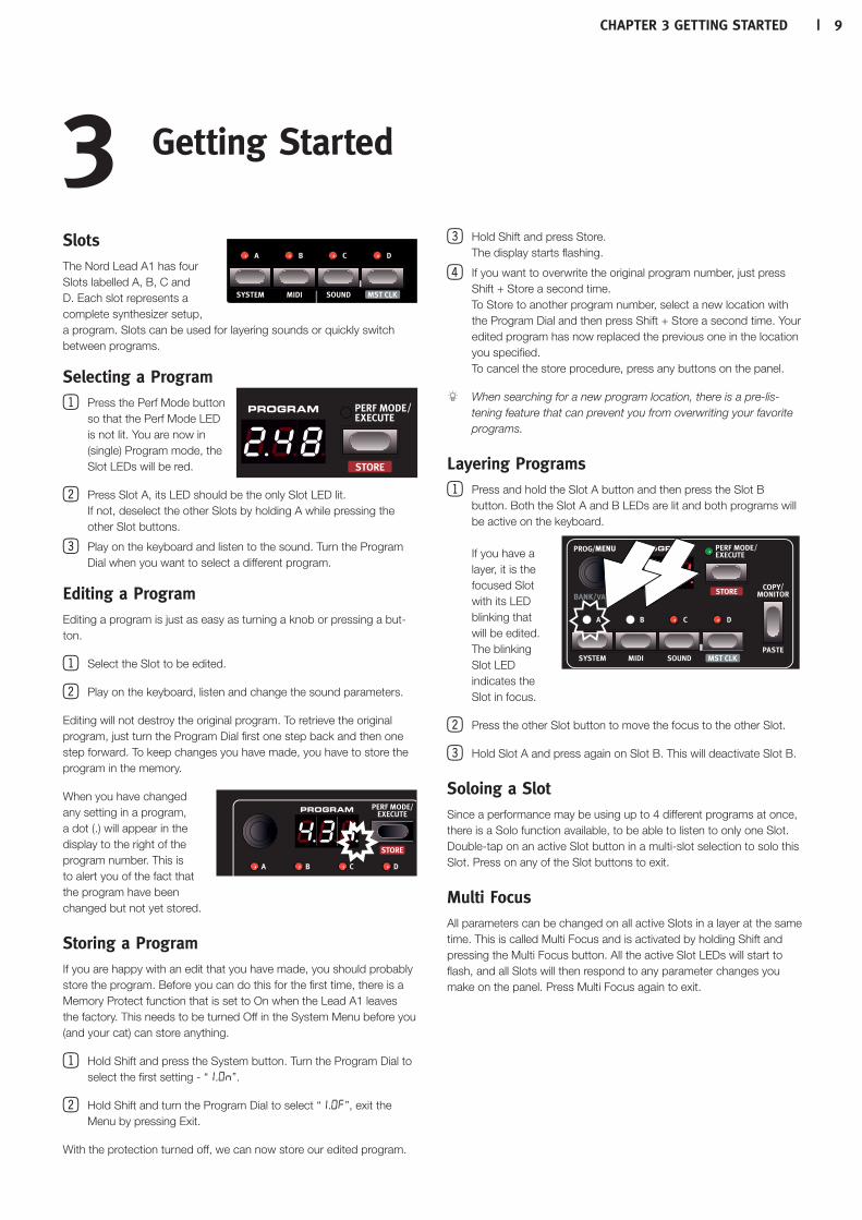
Slots The Nord Lead A1 has four Slots labelled A, B, C and D. Each slot represents a complete synthesizer setup, a program. Slots can be used for layering sounds or quickly switch between programs.
Selecting a Program 1Press the Perf Mode button
so that the Perf Mode LED is not lit. You are now in (single) Program mode, the Slot LEDs will be red.
2Press Slot A, its LED should be the only Slot LED lit. If not, deselect the other Slots by holding A while pressing the other Slot buttons.
3Play on the keyboard and listen to the sound. Turn the Program Dial when you want to select a different program.
Editing a ProgramEditing a program is just as easy as turning a knob or pressing a but-ton.
1Select the Slot to be edited.
2Play on the keyboard, listen and change the sound parameters.
Editing will not destroy the original program. To retrieve the original program, just turn the Program Dial first one step back and then one step forward. To keep changes you have made, you have to store the program in the memory.
When you have changed any setting in a program, a dot (.) will appear in the display to the right of the program number. This is to alert you of the fact that the program have been changed but not yet stored.
Storing a ProgramIf you are happy with an edit that you have made, you should probably store the program. Before you can do this for the first time, there is a Memory Protect function that is set to On when the Lead A1 leaves the factory. This needs to be turned Off in the System Menu before you (and your cat) can store anything.
1Hold Shift and press the System button. Turn the Program Dial to select the first setting - “1.ON”.
2Hold Shift and turn the Program Dial to select “1.OF”, exit the Menu by pressing Exit.
With the protection turned off, we can now store our edited program.
3Hold Shift and press Store. The display starts flashing.
4 If you want to overwrite the original program number, just press Shift + Store a second time. To Store to another program number, select a new location with the Program Dial and then press Shift + Store a second time. Your edited program has now replaced the previous one in the location you specified. To cancel the store procedure, press any buttons on the panel.
When searching for a new program location, there is a pre-lis-tening feature that can prevent you from overwriting your favorite programs.
Layering Programs1Press and hold the Slot A button and then press the Slot B
button. Both the Slot A and B LEDs are lit and both programs will be active on the keyboard. If you have a layer, it is the focused Slot with its LED blinking that will be edited. The blinking Slot LED indicates the Slot in focus.
2Press the other Slot button to move the focus to the other Slot.
3Hold Slot A and press again on Slot B. This will deactivate Slot B.
Soloing a SlotSince a performance may be using up to 4 different programs at once, there is a Solo function available, to be able to listen to only one Slot. Double-tap on an active Slot button in a multi-slot selection to solo this Slot. Press on any of the Slot buttons to exit.
Multi FocusAll parameters can be changed on all active Slots in a layer at the same time. This is called Multi Focus and is activated by holding Shift and pressing the Multi Focus button. All the active Slot LEDs will start to flash, and all Slots will then respond to any parameter changes you make on the panel. Press Multi Focus again to exit.
3Getting Started

10 | nordLeada1USerManUaLv1.3x
Creating a SplitWhen the Split function is ON, the lower part of the keyboard plays on Slots A and B and the upper part on Slots C and D.
1Hold Slot A and press Slot C to activate both these slots.
2Hold Shift and press Split. This splits the keyboard in two halves. Slots A and B will be to the left, Slots C and D to the right.
Setting the Split pointHold Shift and press and hold the Split button. A note number will be indicated in the display. While still holding the buttons, play a key on the keyboard, this key will be the lowest key of the upper range.
Copy and Paste between Slots
Settings from one Slot can be copied to a virtual clipboard and then be pasted to another Slot. This can be useful if a program needs to be moved from the lower part (A and B) to the upper part (C and D).
1Hold Copy and press the source Slot button. “CP” and a letter that indicates which Slot you have copied will be shown in the display.
2Hold Shift + Paste, and press the Slot button where you want your settings to be copied to. “PS” and the destination Slot will be shown in the display.
The content of the virtual clipboard will remain until you copy another setting or parameter, or turn off the Nord Lead A1. This makes it pos-sible to paste the same data to several destinations.
M If you want to keep the new settings you have created by copying, make sure to save the program or performance.
Working with PerformancesTo handle layers, splits on/off, split points and keyboard octave shift, there is a need for storing and loading complex scenarios. This is done with the Performance Mode function. In Performance Mode, all slots and their active status are stored.
Selecting Performances1Press the Perf Mode button to select the Performance Mode.
2Turning the Program Dial will scroll through the 200 perfor-mances, “A. 1” to “d.50”. As you will notice, some of the performances are made with several Slots on top of each other, others are in split configura-tions with different sounds to either side of the keyboard.
Editing a PerformanceTo replace one of the programs in a performance, hold the Slot button with the program you wish to replace and turn the Program Dial.
Storing a PerformanceStoring a performance uses the same procedure as storing programs, see page 9.
Storing Programs as a PerformanceIf you have made layers or splits in Program Mode, you can transfer this to a Performance during the Store process.
1Hold Shift and press Store. The display starts flashing.
2Press Perf Mode to activate Performance Mode.
3Select the desired Performance location and press Shift + Store a second time.
Setting up a MorphThe Morph is a powerful method to control one or several parameters in real-time, with the Modulation Wheel or Keyboard Velocity. A Morph is very easy to set up.
1Hold one of the Morph buttons, let’s use the Wheel in this example.
2While holding the Wheel Morph button, turn a parameter knob, like the Filter Freq.
3Release the Morph Wheel button. The Modulation Wheel can now be used to control the filter frequency.
M The range that the Morph (Modulation Wheel) controls will be the range that was set when you turned the Filter Freq knob.
Read more about Morphing on page 13.

Chapter4SlotSandMeMory | 11
General OverviewThe Nord Lead A1 is a four part multi timbral synthesizer. This means that you have four independent synthesizers to be used simultaneously. The synthesizers are divided into Slots, where each Slot contains one synthesizer. The Slots are called A, B, C and D. The panel shows and edits the features of one Slot at a time. Which Slot that is edited is determined by the Slot focus. A Slot can either be active or not. All active Slots respond to keyboard input as shown in Figure 1. If several Slots are active it is called a layer.
All active Slots respond to keyboard input. Modulation Wheel, Pitch Stick and Control Pedal always reach all slots.
Each of the Slots can listen to different MIDI channels and respond to different keyboard zones. Pitch Stick, Modulation Wheel and Control Pedal reaches all Slots regardless of focus and their active state.
The global channel acts just like playing on the keyboard. The individual slot channels give multi timbrality. MIDI output is always sent on the global channel.
Slot HandlingThe Slot buttons, labelled A to D, are used to set the Slot focus, and the active state of the Slots. To change focus to another Slot, simply press that Slot button. If focus is set to an inactive Slot, that Slot will become active, and the others deactivated. If only one Slot is active, the focused Slot LED will be lit. When several slots are active, the focused Slot LED will be flashing, and the other active slots will have their LEDs lit. A layer is created by pressing several Slot buttons at once. You can also hold one of the Slot buttons pressed, then tap another Slot button to activate / deactivate it.
SplitBy creating a Split point, the keyboard is divided into two zones, where the lower zone (the left part) plays on Slot A and B, and the upper on Slot C and D. Create a Split Point by holding Shift + Split and pressing the note on the keyboard where you want the Split Point.
SoloIf you double-tap on a Slot button, that Slot enters Solo mode. The other Slots are temporarily deactivated and any audio from them is muted. The Solo mode is indicated with a single flashing Slot LED. Press any Slot button to exit Solo mode and return to the previous state.
Multi FocusBy using Multi Focus, Slot focus can be set to multiple Slots simulta-neously. Any changes that are made on the panel then affect all the focused Slots. To turn Multi Focus on, simply press Shift + Multi Focus and all active slots become focused. The focused Slots are indicated with flashing Slot LEDs.
Mod.Wheel
PitchStick
Active
Keyboard
yes yes no no
A B C D
Active yes yes no no
A B C D
MIDI Input MIDI OutputGlobal Channel Global Channel
Slot ChannelA
ABCD
G G
A B C DProgram A Settings
.
.
.
.
...
A B C DPerformance A Settings
.
.
.
...
Mod.Wheel
PitchStick
Active
Keyboard
yes yes no no
A B C D
Active yes yes no no
A B C D
MIDI Input MIDI OutputGlobal Channel Global Channel
Slot ChannelA
ABCD
G G
A B C DProgram A Settings
.
.
.
.
...
A B C DPerformance A Settings
.
.
.
...
4Slots and Memory

12 | nordleada1USerManUalv1.3x
Program HandlingThe A1 handles two different program entities; Programs and Perfor-mances. The memory contains 400 Programs divided into 8 banks, and 200 Performances divided into 4 banks.
ProgramsA Program contains parameter settings for a single synthesizer Slot. A program can be loaded into any of the Slots.
A Program contains parameter data for a single slot.
PerformancesA Performance contains parameter data for all four Slots at once. The parameter data for each slot is stored in the Performance – it is not a reference to a Program. Furthermore the Performance contains settings about Slot Focus, Slot Activation, Hold, Split On/Off, Split Point, Keyboard Octave Shift and Multi Focus.
A Performance contains parameter data for all four slots and com-mon settings.
Performance ModeThe Perf Mode button is used to cycle between Performance Mode and Program Mode. When in Performance Mode the Slot LEDs are green and the display shows the current bank as a letter: “A”, “b”, “C” or “d”. In Program Mode, the Slot LEDs are red and the bank is shown as a single digit “1” to “8”. Program Mode and Performance Mode have separate Slot buffers. This means that the changes to you make in Performance Mode, will not affect the Slots in Program Mode, and vice versa. A Performance is useful not only to create layers, but to load four Slots at once. You can then quickly change between these sounds with the press of a button instead of using the Program Dial.
LoadingTo load from memory, simply turn the Program Dial. When in Perfor-mance Mode entire Performances are loaded and all Slots are affected. In Program Mode only the focused Slot is loaded, leaving the others untouched. A Performance can be built from existing Programs by loading separate Slots in Performance Mode. Load the Slot by pressing and holding a Slot button, and turning the Program Dial. The Program is then loaded into the selected Slot, not affecting the others. The program focus for that Slot is stored in the Performance as an indication to where that sound came from.
StoringStoring works exactly as loading, but the other way around. In Per-formance Mode all four Slots and their common settings are stored to Performance Memory. In Program Mode, only the focused Slot is stored to Program Memory. To store a sound, press Shift + Store. The location to where the sound will be stored in Memory will flash on the display. Change the store location by turning the Program Dial. The sound in that location is tem-porarily loaded so that you can hear what you are about to overwrite. Confirm the store operation by pressing Shift + Store again. While selecting the store location you can change between Perfor-mance and Program Mode. This is very useful to store all Slots as a Performance, or to store one Slot in a Performance as a Program.
Details about storing for the first time can be found in the Getting Started chapter on page 9.
Copying Slots to a PerformanceIf you have added several slots together with the Lead A1 in Program mode, a Performance can be easily created with this selection. Hold Copy and press Perf Mode to copy the slots and their settings to a Performance. The display will show the current performance bank and two dashes “- -“ to alert you that this performance have not yet been stored.
Copying a Performance to ProgramIt is possible to copy all the individual Slots in a Performance, to become a multi-slot selection in Program mode. While in Performance Mode, hold Copy and press Perf Mode. The Lead A1 will switch from Performance to Program mode, with all the Slot settings as they were in the Performance.
Mod.Wheel
PitchStick
Active
Keyboard
yes yes no no
A B C D
Active yes yes no no
A B C D
MIDI Input MIDI OutputGlobal Channel Global Channel
Slot ChannelA
ABCD
G G
A B C DProgram A Settings
.
.
.
.
...
A B C DPerformance A Settings
.
.
.
...
Mod.Wheel
PitchStick
Active
Keyboard
yes yes no no
A B C D
Active yes yes no no
A B C D
MIDI Input MIDI OutputGlobal Channel Global Channel
Slot ChannelA
ABCD
G G
A B C DProgram A Settings
.
.
.
.
...
A B C DPerformance A Settings
.
.
.
...
Chapter5Morph | 13
MorphingMorphing allows you to be creative in your sound design, and is all about being able to control virtually any important sound related parameter, in real time from the two Morph sources: the Modulation Wheel & Control Pedal and the velocity of the keyboard. There are 22 available continuous parameters that can be Morphed. This gives you plenty of real-time control possibilities. A Morph is very simple to set up and use, and all Morph assignments that you make are stored with the program or performance. Many, if not all of the factory programs have morph assigned param-eters. If a program uses a Wheel or velocity Morph, the green Morph indicators on the panel will be lit to indicate this. A Morph Source controls the range from the parameter’s original position in the program, to a position you define when you set up the Morph. This means that you can control a very small range on one param-eter at the same time as you control a very large range on a another parameter. One parameter can be controlled clockwise, and another parameter can be controlled counter clockwise.
The MorphsLet’s look at the Morph Sources:
Wheel/Control PedalThis allows you to use the Modulation Wheel or incoming MIDI CC 01 messages and/or a control pedal as the Morph Source.
•The bottom position of the Modulation Wheel and/or control pedal represents the parameters original setting.
•The top position of the Modulation Wheel or control pedal represents the parameters morphed setting.
If the control pedal is set to control the overall volume of the Nord Lead A1, in the System Menu, the wheel and incoming MIDI CC11 messages will be the Morph source. In addition to this, if Wheel Mode in the System menu is set to Vibrato, incoming MIDI CC11 will be the only Wheel/Pedal Morph source.
Velocity This Morph source uses the Note Velocity from the Nord Lead A1 keyboard and from any incoming MIDI messages.
•A key velocity of 1 represents the parameters original setting.
•A key velocity of 127 represents the parameters maximum morphed setting.
Assign a Morph source to a parameter1Hold a Morph Source button.
2Move the knob of the parameter you wish to control with the Morph Source. Turn it to the setting you want as the maximum Morphed setting.
The selected parameter’s green LED will indicate that a Morph is active.
3Release the Morph Source button.
When the Morph source is operated, the parameter’s setting will change accordingly and influence the sound.
If the original setting of a parameter is changed after a Morph is setup, the Morph range will not be affected, but it will “move” to reflect the new initial setting of the parameter.
Morph parametersA Morph can control most of the continuous parameters. Each one of these have a green LED next to its knob:
Morph Destinations
Arpeggio Rate Glide LFO Rate/Time LFO Clk Div
Mod Env Attack Mod Env Decay Mod Env Release Osc LFO Amt
Osc Modenv Amt Osc Ctrl Filt LFO Amt Filt Modenv Amt
Filter Freq Filter Res Filter Drive Amp Env Attack
Amp Env Decay Amp Env Release FX Rate/Amt* Output Level
Arp Clk Div Delay Tempo* Dly Clk Div* Delay Dry/Wet*
Reverb Dry/Wet*
M * FX Rate/Amt, Delay Tempo, Delay Clock Div., Delay Dry/Wet and Reverb Dry/Wet can not be Morphed with velocity.
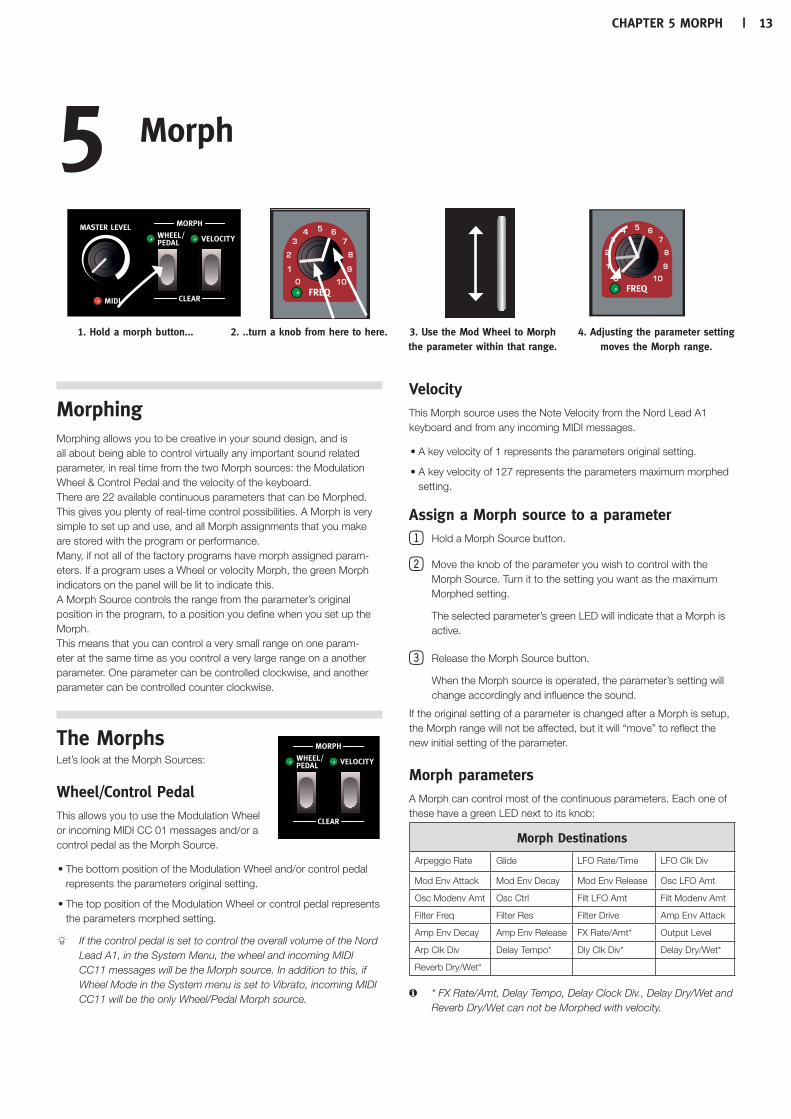
5Morph
1. Hold a morph button... 2. ..turn a knob from here to here. 3. Use the Mod Wheel to Morph the parameter within that range.
4.Adjusting the parameter setting moves the Morph range.

14 | NordLeada1UserMaNUaLv1.3x
Editing Morphs Edit a parameter’s Morph range:
•Hold the Morph Source button and turn the destination knob to a new position.
Clear all parameters assigned to a Morph Source:
•Hold Shift and press the Morph Source button that is to be cleared.
Clearing one parameter from a Morph:
•Hold the Morph Source button and turn the parameter knob to its original position. The green parameter Morph LED will be switched off.
•Double-click on a Morph button to latch the Morph, then hold Shift and turn the knob of the parameter you wish to clear.
Copy and paste a Morph setup
•Hold Copy and press the Morph button that is to be copied to the virtual clipboard. “CPy” will be shown in the display. Hold Shift and Paste, then press the destination Morph button. “Pst” will be shown in the display.
Morph Programming LatchMorphs can be latched, making it possible to lift your finger off the Morph button while setting up the Morph. It provides a great overview that can simplify setting up and adjusting multiple Morph Destinations at once.
1Double-click on one of the Morph Source buttons.
The Morph Source button flashes continuously, and green LEDs on the panel will show any of the parameters that are assigned to this Morph source.
2Operate a parameter that you want to be Morphed.
Press any of the Morph Source buttons to exit Morph Latch Mode.

Chapter6Mutator,randoMize&Like | 15
Mutator The Nord Lead A1 Mutator is a great and easy-to-use tool to spark the creative process by creating totally new or slightly changed sounds.
Executing the Mutation 1Hold Shift and press Mutate Sound.
The Nord Lead A1 Mutator uses probability and degrees of preser-vation, together with some secret smartness. The Mutation will use the sound in the focused Slot as the reference or starting point. If a Mutation is executed more than once without you changing any setting on the panel, it will return to, and use that same starting point for each new Mutation. Turn a knob or press a switch if you want an edited or Mutated sound to become the new starting point.
If Multi Focus is enabled, the Mutation will be executed on all the active Slots.
Some parameters are never changed by the Mutator process: Output Level, all Arpeggio and Reverb parameters and Mono/Legato.
Randomize The Randomize option is a totally random process that does not consider any current or previous pro-grams, music styles, or fashions. Any setting to any parameter can appear, you should not be surprised if a randomized program needs a little bit of adjust-ment before it can be used for such mundane things as chords or melodies.
M If Mutator Protect in the System Menu is set to On, you need to confirm your intentions by pressing Execute, or by hitting Mutate- or Randomize Sound two times.
Mutate MorphThe Mutator and Randomize features in the Nord Lead A1 can be used to create Morphs.
1Hold the Morph Wheel button (or latch the Morph by double-tapping on the Morph button) and press Mutate Sound (without Shift). Several Morph settings will be added to the original sound, as indicated by the green LEDs that lights up on the Panel. If effects are turned off they will be turned on but with rate and dry/wet mix set to 0 as a starting point for the wheel morph.
2Move the Modulation Wheel to hear the result. The original sound is heard when the Mod Wheel is set to 0, the Morphed sound is heard when the Mod Wheel is moved to its maximum.
The Mutator can be applied to Velocity Morphs as well, but will not af-fect the effect section. The original sound will be heard when you strike the keys with a velocity of 1, the fully Morphed sound when the velocity is 127.
If the Oscillator LFO Amount, Oscillator Mod Env Amount and the Oscillator Control parameters are all set to 0, the Morph Mutation will be able to change the Oscillator Configuration.
M If Osc Config is set to the Amplitude Modulation or Detune con-figurations, the configuration will not change.
Randomizing a Morph is done in a similar fashion, but by pressing the Randomize Sound button instead. This will create a “wilder” result.
6Mutator, Randomize & Like

16 | nordLeada1userManuaLv1.3x
Like 1Hold Shift and press Like.
The Like button lets you save programs or entire performances to the Like memory. The Like mem-ory acts like a scratchpad that can be used during the creative process so save sounds that you might want to keep. Performances and programs have separate Like memories, with 50 locations each. When you have reached the 50th Like location, the next Like will overwrite the content in the 1st location. The Like memory is temporary and will be cleared when the Nord Lead A1 is powered off.
Program LikesPressing Like when Program Mode is active, will save the sound in the focused slot to the Program Like memory.
M Using Like when Multi Focus is active will de-activate Multi Focus, leaving the previously focused single Slot active and save this Slot in the Like memory. The other Slots will retain any edits you made using Multi Focus.
Performance LikesPressing Like when in Performance Mode, will save the entire perfor-mance to the Performance Like memory.
M If a program or a performance is identical with what was previ-ously saved in the Like memory, it will not be saved again.
Select a Like to Store 1Press Shift + Store to store a Like that you
wish to keep.
1Find a location by turning the Program Dial and press Shift + Store a second time to store the sound.
The Like memory browser becomes available when a program or performance is Liked, indicated by the initial letter “L” in the display. Browse through the Liked sounds by turning the Program Dial. Press Store if you want to permanently store the liked sound to one of the regular memory locations, or just press Exit to leave the Like memory browser.

Chapter7panelreferenCe | 17
7Panel Reference
Master Level The Master Level knob controls the overall ampli-tude for the audio outputs - the line level outputs and the headphone output. The knob’s physical position indicates the output level and is not stored in a Program or Performance.
If you need to adjust the output level in individual programs, use the Output parameter in the upper right area on the panel. The setting of that control is stored.
MIDI LEDThe MIDI LED will indicate incoming MIDI messages by briefly lighting up. Short LED flashes indicates that MIDI messages are received but not used in any way by the Nord Lead A1. Longer flashes are indications that the MIDI messages are actually recognized. This applies to mes-sages on MIDI channels that are in use, CC messages that will change Nord Lead A1 parameters, etc..
Morph Morphs are used to gradually change one or several parameters with the Morph Controls - the keyboard velocity and the Modulation Wheel and Control pedal - while you are playing. Hold a Morph button and turn a knob to set the Morph controller, the parameter destination and the range of the Morph control.
For a detailed description on how to use Morphs, please look at page 13.
Program/Value Dial Turn the Program/Value Dial to select programs or performances. When any of the Menus are entered, the Program Dial is used to select the menu functions and to change settings.
The Program Dial is endless, though the array of parameter settings are not. Once you reach the first or last possible setting, turning the Program Dial further will have no effect.
The Program Dial has an accelerator feature; when operated swiftly you scroll through values in larger increments.
LED DisplayThe LED display will show which program or performance is active. Menu functions, menu settings, confirmation of executed actions and parameter values are also displayed when appropriate.
Performance Mode/Execute Pressing the Perf Mode button will toggle between Program and Performance Mode. Programs are shown in the LED display as a two or three digit number between 1. 1 and 8.50 and the Slot LEDs will be red. Program mode is typically used to play with one Slot, one program at a time.
Performances can use up to 4 slots with 4 simultaneous programs in various combinations - splits, layers, keyboard controlled and MIDI input. Performances are indicated by initial letters “A”, “b”, “C” or “d” followed by a number from 1 to 50 with green Slot LEDs.
Hold a Slot button and turn the Program Dial to load another program in that Slot.
Commands and actions - the Store command, Mutator, Initialize, Randomize and MIDI actions that are found in the Menus - that needs confirmation will be indicated by flashing characters in the display. Press Execute to confirm or to start the action or the process.
StoreStore is used when program or performance settings are to be stored in the Nord Lead A1 memory. Read more about the Store procedure on page 9.
Copy/Monitor Use this feature to Copy settings to be pasted to new desti-nations, and to monitor individual parameter settings. Hold Copy and press a Morph or a Slot button.
Copies can be made from Morphs and entire Slots (com-plete Programs). A copy can be pasted several times, the content of the clipboard is kept until another copy is made or the Nord Lead A1 is turned off. A selection of active Slots can all be copied to a Perfor-mance, and a Performance can be copied to Program mode. Read more about this on page 12.
“Cpy” (followed by a number or letter when appropriate) will be dis-played when a Morph or a Slot is copied. A parameter’s value is shown in the display when it is copied.
Paste Hold Shift + Paste and select a destination to paste the copied data. “PSt”, or “PS” and the Slot (or the value of the single parameter) will be displayed.
Monitor
You can use this feature to monitor the value of a setting in the display, by holding this button and turning a knob.
18 | nordleada1UserManUalv1.3x
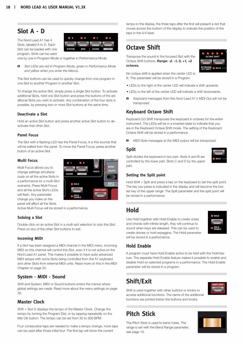
Slot A - D The Nord Lead A1 has 4 Slots, labeled A to D. Each Slot can be loaded with one program. Slots can be used one by one in Program Mode or together in Performance Mode.
M Slot LEDs are red in Program Mode, green in Performance Mode and yellow when you enter the Menus.
The Slot buttons can be used to quickly change from one program in one Slot to another Program in another Slot.
To change the active Slot, simply press a single Slot button. To activate additional Slots, hold one Slot button and press the buttons of the ad-ditional Slots you wish to activate. Any combination of the four slots is possible, by pressing two or more Slot buttons at the same time.
Deactivate a Slot
Hold an active Slot button and press another active Slot button to de-activate that other Slot.
Panel Focus
The Slot with a flashing LED has the Panel Focus, it is this sounds that will be edited from the panel. To move the Panel Focus, press another button of an active Slot.
Multi Focus
Multi Focus allows you to change settings simultane-ously on all the active Slots in a performance (or a multi-Slot scenario). Press Multi Focus and all the active Slot’s LEDs will flash. Any parameter change you make on the panel will affect all the Slots. Active Multi Focus will be stored in a performance.
Soloing a Slot
Double-click on an active Slot in a multi-slot selection to solo this Slot. Press on any of the other Slot buttons to exit.
Incoming MIDI
If a Slot has been assigned a MIDI channel in the MIDI menu, incoming MIDI on this channel will control this Slot, even if it is not active on the Nord Lead A1 panel. This makes it possible to have quite advanced MIDI setups with some Slots being controlled from the A1 keyboard, and other Slots from external MIDI units. Read more on this in the MIDI Chapter on page 32.
System - MIDI - Sound Shift and System, MIDI or Sound buttons enters the menus where global settings are made. Read more about the menu settings on page 30.
Master ClockShift + Slot D displays the tempo of the Master Clock. Change the tempo by turning the Program Dial, or by tapping repeatedly on the Mst Clk button. The tempo can be set from 30 to 300 BPM.
Four consecutive taps are needed to make a tempo change, more taps can be used after those initial four. The first tap will show the current
tempo in the display, the three taps after the first will present a dot that moves across the bottom of the display to indicate the position of the taps in the 4/4 beat.
Octave Shift Transpose the sound in the focused Slot with the Octave Shift buttons. Range: -2. -1, 0, +1, +2 octaves.
No octave shift is applied when the center LED is lit. This parameter will be stored in a Program.
•LEDs to the right of the center LED will indicate a shift upwards.
•LEDs to the left of the center LED will indicate a shift downwards.
M Keyboard messages from the Nord Lead A1’s MIDI Out will not be transposed.
Keyboard Octave ShiftKeyboard Oct Shift transposes the keyboard in octaves for the entire instrument. The LEDs will be in a inverted state to indicate that you are in the Keyboard Octave Shift mode. The setting of the Keyboard Octave Shift will be stored in a performance.
M MIDI Note messages at the MIDI output will be transposed.
Split Split divides the keyboard in two part. Slots A and B are controlled by the lower part, Slots C and D by the upper part.
Setting the Split point
Hold Shift + Split and press a key on the keyboard to set the split point. The key you press is indicated in the display and will become the low-est key of the upper range. The Split parameter and the split point will be stored in a performance.
Hold Use Hold together with Hold Enable to create notes and chords with infinite length, they will continue to sound when keys are released. This can be used to create drones or hold arpeggios. The Hold parameter will be stored in a performance.
Hold EnableA program must have Hold Enable active to be held with the Hold fea-ture. The separate Hold Enable feature makes it possible to enable and disable Hold on selected programs in a performance. The Hold Enable parameter will be stored in a program.
Shift/Exit Shift is used together with other buttons or knobs to access additional functions. The name of the additional functions are printed below the buttons and knobs.
Pitch Stick The Pitch Stick is used to bend notes. The range is set with the Bend Range parameter, see page 19.

Chapter7panelreferenCe | 19
Modulation Wheel The Modulation Wheel can add vibrato if the Vibrato Voice Mode set-ting is set to “Wheel” and/or act as a Morph Control, to control one or several parameters while you perform. The Modulation Wheel will transmit MIDI CC 01.
Arpeggiator Use the arpeggiator to au-tomatically play a repeated sequence of notes based on notes or chords you play on the keyboard.
Arpeggio RunStarts and stops the arpeggiator.
Arpeggio RateThe tempo of the eight note arpeggio is set by the Rate knob, with a range from 16 BPM to "F5", which is "very fast".
Arpeggio Mst ClkHold Shift and turn Rate to lock the arpeggiator to the Master Clock. Rate will then be used to select the time divisions.
Arpeggiator Divisions
Division Description
2, 4, 8, 16, 32 The straight divisions range from 1/2 notes to 1/32 notes.
2t, 4t, 8t, 16t The t indicates the triplet divisions.
Arpeggio RangeThe arpeggiator has a range from 1 to 4 octaves.
Arpeggio DirectionsThe arpeggio directions are: Up (no LED), Down (DN), Up/Down (U/D) and Random (Rnd).
PanicIf notes would ever sustain indefinitely during a performance, press Shift and Panic. This will execute an internal All Notes Off command, and reset incoming MIDI CC messages.
Voice Mode UnisonUnison stacks de-tuned voices “on top of each other,” in the same fashion as on the classic analog polyphonic synthesizers. Unison will po-sition voices left and right with various strengths in the stereo panorama.
•Unison 1 is two slightly detuned and panned voices.
•Unison 2 is four slightly detuned and panned voices.
•Unison 3 is four voices with a stronger detuning and panning.
Mono Mono makes the Slot monophonic, only one note at a time will be heard. The envelopes will be re-triggered for each new note you play.
LegatoLegato is another monophonic mode. The envelopes will not be re-triggered if you play legato, they will continue in their present phase.
Legato is when you play a key without releasing a previously played key.
GlideGlide can be used to set the time interval for the pitch to glide from one note to a new note, when Mono or Legato is active. With a setting of zero the pitch will change instantly.
M If Legato is active, Glide will only occur if you play legato.
Multi FocusMulti Focus allows you to change settings simultaneously on all the active Slots. Press Multi Focus and the active Slot’s LEDs will flash. Any parameter change you make on the panel will affect all the Slots. Active Multi Focus can be stored in a performance. Press a Slot but-ton to exit.
Bend Range Bend Ranges can be different for each program and can be set to a maximum of +/- 48 semitones. There are also two settings with dif-ferent ranges for the upward and downward bend.
Press Shift + Bend Range repeatedly. The first press will display the current setting, each consecutive press will increase the bend range one step at a time.
Hold Bend Range and turn the Program Dial to scroll through the available settings.
Bend Range Description
Off Pitch Bend is disabled.
1 - 12, 24, 48 Pitch Bend range in semitones.
-12, -24 Pitch Bend range is 2 semitones for upward bends, and 12 or 24 semitones for downward bends.
Vibrato The Dly1 and Dly2 settings add a delayed vibrato, the delay time being 0.5 and 1.0 seconds. The vibrato rate and the depth of the delayed vibrato is set in the Sound Menu. When Wheel is selected, the depth of the vibrato is controlled by the Modulation Wheel and incoming MIDI CC 01.
Init SoundPressing Shift + Init Sound provides you with a neutral starting point for all parameters if you want to begin programming a sound from scratch. You need to confirm your intentions by pressing Execute or pressing Init Sound again.

20 | nordleada1UserManUalv1.3x
Low Frequency Oscillator (LFO/ENV) The Low Frequency Oscillator (LFO) produces a waveform that can be used to create cyclic modula-tions to the oscillators and filter. The Nord Lead A1 LFO can also be set to an envelope mode. The amount of modulation is set with the LFO amount knobs in the oscillator and filter sections. The LFO can be synchronized to the Master Clock.
M The LFO in the Nord Lead A1 is monophonic.
Rate/TimeThe Rate knob sets the frequency of the LFO. Range: 0.03 to 523 Hz.
LFO Master Clock (Mst Clk) Enable Mst Clk (Shift + Rate/Time knob) to synchronize the LFO to the Master Clock. The Rate knob will be used to control the time division.
Division Description
4b, 2b, 1, 2, 4, 8, 16, 32, 64
The straight divisions range from 4 bars to 1/64 notes.
4bt, 2bt, 1t, 2t, 4t, 8t, 16t, 32t
The t indicates the triplet divisions, from 4 bars to 1/32 notes.
LFO Waveform Selector
Waveform Description
SquareUsed for abrupt modulation changes, suitable for trills, distinct tremolos, etc.
SawtoothUsed for linear ramp type modulations.
Inverted SawtoothInverted linear ramp.
TriangleSuitable for natural vibrato effects, also good for classic pulse width modulation.
S/H Stepped RandomRecreates a stepped random modulation.
EnvelopeThe cyclic behavior of the LFO can be changed to behave as an enve-lope. Press Shift + LFO waveform selector to enable this feature. The Time control will depend on the selected waveform.
M When the LFO is used as an envelope, it is polyphonic.
Waveform Description
A gated envelope, the Time control sets the gate-time.
Decaying envelope, the Time control sets the decay time.
Attack envelope, the Time control sets the attack time.
A/D envelope, the Time control sets the envelope duration.
S/H S/H random values that are generated for each key. The Rate/Time knob sets a time lag from one value to the next.
LFO Modulation Polarities The modulation of the LFO is unipolar, with a few exceptions. Pitch and PW modulations with triangle and S&H waveforms are bipolar.
Modulation Envelope The polyphonic Modulation Envelope is a ADR/ASR envelope that can be used to modulate the oscillators and/or the filter in the Nord Lead A1.
AttackAttack is the time it takes for the modulation envelope to reach the maximum modulation level. This envelope phase begins when you press a key. Range: 0.45 ms to 45 s.
Decay The Decay begins after the attack phase is completed. It is the time it takes for the modula-tion envelope to drop back down to zero again. If Decay is turned fully clockwise, the decay will be infinite, acting as a sustain level. Range: 3.0 ms to 45 s, Sustain.
ReleaseThe Release phase of the envelope begins after you have released the key. This setting determines how long it should take for the envelope to drop to zero after the key is released. The release phase may start anywhere during the envelope’s other phases, it will begin as soon as a key is released as shown in this illustration. Range: 3.0 ms to 45 s.
decay (time) release (time)
key down key up
attack (time)
time
amount
sustain release (time)
key down key up
attack (time)
time
amount
release (time)
key down key up
attack (time)
time
amount

Chapter7panelreferenCe | 21
Inverted Envelope Hold Shift and turn the Decay knob to invert the polarity of the Modulation Envelope.
Env VelHold Shift and turn the Release knob to make the amplitude of the Modulation Envelope velocity sensitive.
Oscillators The oscillator is the foundation of the sound in a synthesizer. It produces the waveform with its harmonic content. This important property of the sound can then be shaped and/or modulated.
The Nord Lead A1 features a newly developed Wave Engine with unique Oscillator Configura-tion Shortcuts utilizing one or two oscillators. Start with an Oscil-lator waveform from a choice of multiple analog and digital waves, select an Oscillator Configuration Shortcut - Pitch, Detune, Shape, Sync, FM, AM, Dual Osc or Noise - and use the Osc Control knob to adjust the settings of the configura-tion.
Panel Analog Waveforms
Shape Mode
Shape = 0. Shape = 5. Shape = 10.
Pulse
Saw
Triangle
Sine
Extended Analog Waveforms
Shape Mode
Shape = 0. Shape = 5. Shape = 10.
A1
A2
A3
A4
A5
A6
A7
M A6: Exponential Saw. A7: Exponential Square.
Fixed Pulse Waveforms M Fixed Pulses will keep the width even if the pitch changes.
Shape Mode
Shape = 0. Shape = 5. Shape = 10.
P1
P2
P3
Drawbar Organ Waveforms
O1 808000000 "Second".
O2 880000000 "Third".
O3 888000000 "Jimmy Smith".
04 888800000 "Blues".
O5 888800008 "Gospel".
O6 808808008 "Church".
O7 800008888 "Squabble".
O8 888888888 "Full Organ".
O9 888888888 +++++ "Full Organ Plus".
Bells and Tines
B1 Inharmonic spectra of vibrating metal bars.
b2 Harmonic version of vibrating metal bars.
b3 Spectra from a vibrating bar with one fixed end.
b4 Metal marimba bar.
b5 Inharmonic spectra of tubular bells.
decay (time) release (time)
key down key up
attack (time)
time
amount

22 | nordleada1UserManUalv1.3x
Digital
d1 Saw spectra with random phase.
d2 Square spectra with random phase.
d3 Spectra with only even partials.
d4 Spectra with only every third harmonic.
d5 Spectra with only every fourth harmonic.
d6 Spectra with only every fifth harmonic.
d7 Tripplets.
d8 Ice.
Electric
E1 Electric Piano 1.
E2 Electric Piano 2.
E3 Clavinet 1.
E4 Clavinet 2.
Formants
F1 Voice "AAA".
F2 Voice "EEE".
F3 Voice "OOO".
F4 Voice "YYY".
F5 Voice "AO".
F6 Voice "AE".
F7 Voice "OE".
Oscillator ConfigurationThe Oscillator Configuration allows you to re-configure the connections and in some cases, the actual functions of the oscillators in the Nord Lead A1. These shortcuts together with the Oscillator Control para-meter can make drastic changes to the timbre of the oscillators. The configurations vary from quite basic with a single oscillator, to complex setups with two oscillators, wave-shaping or FM algorithms. There are 8 types of Oscillator Configurations.
Single Oscillator Configurations
Pitch
The Pitch configuration is a single oscillator, where its pitch can be modulated with the Mod Envelope, the LFO or set or Morphed by the Osc Control. Single oscillator setups can be great for clean bass sounds, and nice, sharp solo sounds.
Shape
This single oscillator configuration uses the Osc Control to act as a powerful waveshaper. The shaping of the Panel Analog, Extended Analog and Fixed Pulse waveforms uses a tradi-tional waveshaping method, the other waveforms are changed with a spectral shaping process.
Sync
This configuration is a Oscillator Hard Sync setup with a “hidden” sync oscillator, that recreates the classic oscillator sync sounds from the 70s. Oscillator Sync results in a multi resonant spectrum with moving peaks.
Noise
One oscillator and a white noise source. The Osc Control sets the mix between oscillator 1 and the noise source.
Dual Oscillator Configurations
Detune
Detune is a configuration with two oscillators where oscillator 2 can be either slightly detuned or tuned in semi tone intervals. If the Panel, Extended Analog or Fixed Pulse waveforms are used, both oscillators will use the same waveform. When any other waveform is used, oscillator 1 will use a sine wave fundamental. Osc Control adjusts the pitch of oscillator 2 with a wide range from a gentle detune to a 60 semitone interval.
OSC 1Pitch
LFOModEnv
Osc Contrl
OSC 1Shape
LFOModEnv
Osc Contrl
OSC 1Pitch
LFOModEnv
Osc ContrlSync Osc
Reset Balance
Noise
LFOModEnv
Osc Contrl
OSC 1
OSC 1 OSC 2Pitch
LFOModEnv
Osc Contrl
BalanceLFO
ModEnvOsc Contrl
OSC 1 OSC 2
OSC 2Pitch
LFOModEnv
Osc Contrl
AM
OSC 1
Freq
LFOModEnv
Osc Contrl
FM
ModulatorOSC 2
To Filter To Filter To Filter To Filter
To FilterTo Filter
To Filter
To Filter
Mix
Amount
CarrierOSC 1
OSC 1Pitch
LFOModEnv
Osc Contrl
OSC 1Shape
LFOModEnv
Osc Contrl
OSC 1Pitch
LFOModEnv
Osc ContrlSync Osc
Reset Balance
Noise
LFOModEnv
Osc Contrl
OSC 1
OSC 1 OSC 2Pitch
LFOModEnv
Osc Contrl
BalanceLFO
ModEnvOsc Contrl
OSC 1 OSC 2
OSC 2Pitch
LFOModEnv
Osc Contrl
AM
OSC 1
Freq
LFOModEnv
Osc Contrl
FM
ModulatorOSC 2
To Filter To Filter To Filter To Filter
To FilterTo Filter
To Filter
To Filter
Mix
Amount
CarrierOSC 1

Chapter7panelreferenCe | 23
Sine, Tri, Saw and Pulse Mix
There are four Mixed configurations that add a second oscillator with a waveform and a harmonic partial relationship to oscillator 1. The Mixed configurations are presented with the waveform and a numerical value of a harmonic partial in the Oscillator Configuration display. Here are a few examples:
SA. Sub (1 octave down).
SA.1 Nominal = Oscillator 1
SA.2 1 octave up.
SA.3 3:rd harmonic.
SA.4 2 octaves up.
SA.5 5:th harmonic.
SA.6 6:th harmonic.
SA.7 7:th harmonic.
SA.8 3 octaves up.
M The waveform of oscillator 1 is the one specified with the Wave-form Dial.
Modulation Configurations
FM (Frequency Modulation)
This is a classic 2 operator FM synthesis configuration where oscillator 1 is the carrier and oscillator 2 is the modulator. The frequency of oscillator 2 is set by the Osc Config dial, with a frequency range of -12 to +48 semitones, relative to oscillator 1.
FM synthesis is a powerful tool for generating a very complex spectra from a simple waveform. FM synthe-sis can create both harmonic and inharmonic sounds depending on the frequency relation between the modulator and the carrier. The most famous FM synthesizer is the DX7 from the mid 1980's.
AM (Amplitude Modulation)
Oscillator 1 will be amplitude modulated by a sine wave from oscillator 2. Osc Control sets the frequency of oscillator 2.
Amp Envelope The Amp envelope is a polyphonic ADR/ASR envelope, used to control how the sound amplitude or level changes over time. By modulating the amplifier with an envelope, the sound can be given its basic “shape”. In fact, the “volume shape” is one of the most important factors in how we identify the sound. By setting up a proper amplifier envelope you can make a sound “soft”, “hard”, “plucked” “static” etc.
AttackAttack is the time it will take for the envelope to go from zero to the maximum amplitude as soon as a key have been pressed. Range: 0.5 ms to 45 s.
Decay Decay is the time it takes for the envelope to drop down to zero after the at-tack phase has been completed. When Decay is turned fully clockwise, it will not drop down at all, but remain at the full sustain level. Range: 0.5 ms to 45 s, Sustain
ReleaseThe Release phase of the envelope begins after you have released the key. This setting determines how long it should take for the envelope to drop to 0 after the key is released. The release phase may start anywhere during the envelope’s other phases. It will begin as soon as a key is released. Range: 3.0 ms to 45 s.
Env VelPress Shift and turn the Release knob to enable Envelope Velocity. This makes the amplitude velocity sensitive.
Sinewave Sub Triangle nom. Saw 1 oct up Square 3:rdOSC 1Pitch
LFOModEnv
Osc Contrl
OSC 1Shape
LFOModEnv
Osc Contrl
OSC 1Pitch
LFOModEnv
Osc ContrlSync Osc
Reset Balance
Noise
LFOModEnv
Osc Contrl
OSC 1
OSC 1 OSC 2Pitch
LFOModEnv
Osc Contrl
BalanceLFO
ModEnvOsc Contrl
OSC 1 OSC 2
OSC 2Pitch
LFOModEnv
Osc Contrl
AM
OSC 1
Freq
LFOModEnv
Osc Contrl
FM
ModulatorOSC 2
To Filter To Filter To Filter To Filter
To FilterTo Filter
To Filter
To Filter
Mix
Amount
CarrierOSC 1
OSC 1Pitch
LFOModEnv
Osc Contrl
OSC 1Shape
LFOModEnv
Osc Contrl
OSC 1Pitch
LFOModEnv
Osc ContrlSync Osc
Reset Balance
Noise
LFOModEnv
Osc Contrl
OSC 1
OSC 1 OSC 2Pitch
LFOModEnv
Osc Contrl
BalanceLFO
ModEnvOsc Contrl
OSC 1 OSC 2
OSC 2Pitch
LFOModEnv
Osc Contrl
AM
OSC 1
Freq
LFOModEnv
Osc Contrl
FM
ModulatorOSC 2
To Filter To Filter To Filter To Filter
To FilterTo Filter
To Filter
To Filter
Mix
Amount
CarrierOSC 1
decay (time) release (time)
key down key up
attack (time)
time
amount
sustain release (time)
key down key up
attack (time)
time
amount
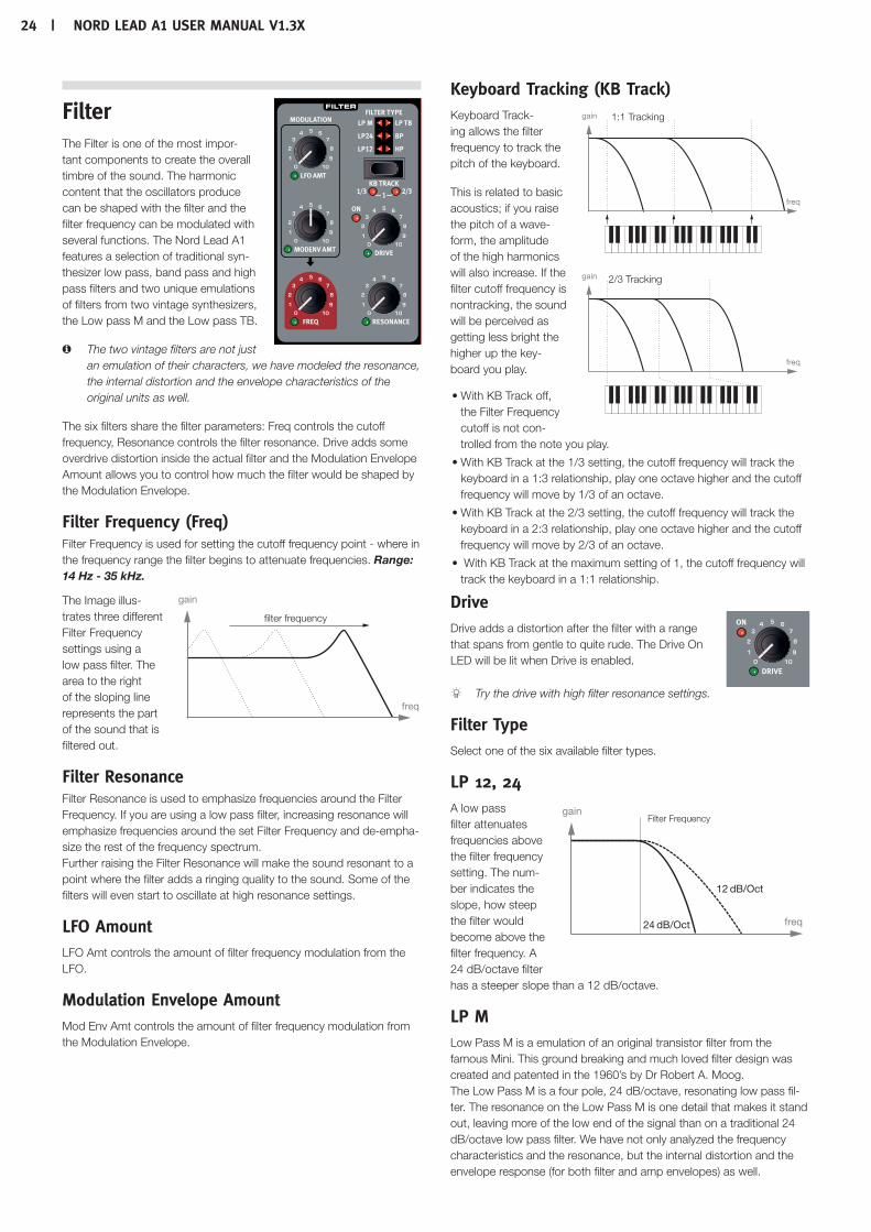
24 | nordleada1UserManUalv1.3x
Filter The Filter is one of the most impor-tant components to create the overall timbre of the sound. The harmonic content that the oscillators produce can be shaped with the filter and the filter frequency can be modulated with several functions. The Nord Lead A1 features a selection of traditional syn-thesizer low pass, band pass and high pass filters and two unique emulations of filters from two vintage synthesizers, the Low pass M and the Low pass TB.
M The two vintage filters are not just an emulation of their characters, we have modeled the resonance, the internal distortion and the envelope characteristics of the original units as well.
The six filters share the filter parameters: Freq controls the cutoff frequency, Resonance controls the filter resonance. Drive adds some overdrive distortion inside the actual filter and the Modulation Envelope Amount allows you to control how much the filter would be shaped by the Modulation Envelope.
Filter Frequency (Freq)Filter Frequency is used for setting the cutoff frequency point - where in the frequency range the filter begins to attenuate frequencies. Range: 14 Hz - 35 kHz.
The Image illus-trates three different Filter Frequency settings using a low pass filter. The area to the right of the sloping line represents the part of the sound that is filtered out.
Filter ResonanceFilter Resonance is used to emphasize frequencies around the Filter Frequency. If you are using a low pass filter, increasing resonance will emphasize frequencies around the set Filter Frequency and de-empha-size the rest of the frequency spectrum. Further raising the Filter Resonance will make the sound resonant to a point where the filter adds a ringing quality to the sound. Some of the filters will even start to oscillate at high resonance settings.
LFO AmountLFO Amt controls the amount of filter frequency modulation from the LFO.
Modulation Envelope AmountMod Env Amt controls the amount of filter frequency modulation from the Modulation Envelope.
Keyboard Tracking (KB Track) Keyboard Track-ing allows the filter frequency to track the pitch of the keyboard.
This is related to basic acoustics; if you raise the pitch of a wave-form, the amplitude of the high harmonics will also increase. If the filter cutoff frequency is nontracking, the sound will be perceived as getting less bright the higher up the key-board you play.
•With KB Track off, the Filter Frequency cutoff is not con-trolled from the note you play.
•With KB Track at the 1/3 setting, the cutoff frequency will track the keyboard in a 1:3 relationship, play one octave higher and the cutoff frequency will move by 1/3 of an octave.
•With KB Track at the 2/3 setting, the cutoff frequency will track the keyboard in a 2:3 relationship, play one octave higher and the cutoff frequency will move by 2/3 of an octave.
• With KB Track at the maximum setting of 1, the cutoff frequency will track the keyboard in a 1:1 relationship.
Drive Drive adds a distortion after the filter with a range that spans from gentle to quite rude. The Drive On LED will be lit when Drive is enabled.
Try the drive with high filter resonance settings.
Filter TypeSelect one of the six available filter types.
LP 12, 24 A low pass filter attenuates frequencies above the filter frequency setting. The num-ber indicates the slope, how steep the filter would become above the filter frequency. A 24 dB/octave filter has a steeper slope than a 12 dB/octave.
LP MLow Pass M is a emulation of an original transistor filter from the famous Mini. This ground breaking and much loved filter design was created and patented in the 1960’s by Dr Robert A. Moog. The Low Pass M is a four pole, 24 dB/octave, resonating low pass fil-ter. The resonance on the Low Pass M is one detail that makes it stand out, leaving more of the low end of the signal than on a traditional 24 dB/octave low pass filter. We have not only analyzed the frequency characteristics and the resonance, but the internal distortion and the envelope response (for both filter and amp envelopes) as well.
filter frequency
freq
gain
freq
gain 1:1 Tracking
freq
gain 2/3 Tracking
Filter Frequency
12 dB/Oct
24 dB/Oct freq
gain

Chapter7panelreferenCe | 25
LP TBLow Pass TB is an emulation of the diode ladder filter from the vintage Roland TB-303 from 1982. This is a four pole, 24 dB/octave design but it does not sound anything like the similarly spec’d LP M. The Low Pass TB has a nice, quirky character to it and will not go into self oscil-lation like the other low pass filters, when resonance is turned up high. Another important feature in this filter is that a set resonance level will drop quite a bit if the filter frequency is lowered.
BP A band pass filter lets frequencies at the filter frequency pass, while frequencies above and below the filter frequency will be attenuated. The Lead A1 band pass filter has a 12 dB/octave slope on each side of the filter frequency.
HPA high pass filter filter will attenuate frequen-cies below the filter frequency, frequencies above the cutoff will not be affected. The slope of the high pass filter is 24 dB/Oct.
FX The Nord Lead A1 has a collection of great effects that can add anything from very subtle to quite drastic changes to the sound. The Rate/Amount knob controls rate or amount depending on the effect used. Turn the knob to "Off" and the effect will be bypassed.
FlangerThe flanger effect is produced by mixing two identi-cal signals together, one signal delayed by a small and gradually changing amount, usually shorter than 20 milliseconds. The delayed signal is also fed back into the signal path. This produces a swept comb filter effect, with a nice swoosh-ing sound. The flanger in the Nord Lead A1 is modeled after a vintage MXR™ unit.
PhaserThe phaser effect is created by splitting the audio signal into two paths. One path passes through a filter that alters the phase. The amount of change in phase depends on the frequency. When the signals from the two paths are mixed together, frequencies that are out of phase will cancel each other out, creating the phaser’s characteristic notches. The phaser in the Nord Lead A1 is modeled after a vintage MuTron™ unit.
RMRing Modulation is an effect that multiplies an audio signal with another. In this case the audio signal from the filter/amplifier will be multiplied with a sine wave. The frequency of this sine wave is controlled by the Rate/Amt knob. At low settings you get a tremolo effect, higher settings
will produce some quite drastic harmonic spectra.
ChorusA Chorus is achieved by taking an audio signal and mixing it with one or more delayed, pitch-modulated copies of itself. The pitch of the added copies are modulated by an LFO. This makes the chorus effect similar to that of a flanger, except that it is created with longer delay times, giving it a more gentle sound. The output of the Chorus in the Nord Lead A1 is in stereo.
EnsembleThe Nord Lead A1 Ensemble effect is modeled after a vintage Eminent organ effect. The very characteristic sound comes from feeding the audio into three separate, modulated delay lines, that are cross-con-nected with each other. The output of the Ensemble in the Nord Lead A1 is in stereo.
DriveThe Drive amplifies the audio signal until it distorts in the same fashion as an overdriven tube style amplifier. This creates that typical asymmet-ric soft clipping with the warm-sounding, even-order harmonics that sounds so nice on almost any sound.
Mutate SoundMutate Sound will create an automatic edit of the current, focused sound. For a more detailed description of the Mutator, please look at page 15.
Delay The Delay can add anything from short, slapback echoes to long, loop type repeats. Since the delay can be synchronized to the Master Clock, it can be a creative component in rhythmic sounds, together with the arpeggio and the LFO. The Delay has 4 feedback levels, a Dry/Wet control and adjustable tempo. The Delay tempo can be set manually or synchronized to the Master Clock and the repeats can be alternating between the left and right output. The Delay features an optional analog mode that behaves like an "old school" delay when changing the delay tempo on the fly.
TempoThe Tempo knob sets the time interval between the repeats. If the Delay is synchronized to the Master Clock tempo, Tempo will set the divisions. Range: 20 ms to 1500 ms.
Division Description
2, 4, 8, 16, 32, 64 The straight divisions range from half notes to 64ths.
4d, 8d, 16d The dotted divisions will add an additional half of the note value. 4d equals one 1/4 and a 1/8th etc...
2t, 4t. 8t, 16t, 32t The t indicates the triplet divisions.
4s, 8s, 16s, The s indicates the swing divisions.
M Divisions are ordered according to their perceived tempo. This is why the “4d” will be before of “2t”, “4s” is before of “4”, and “4t” is after “4” etc..
Filter Frequency
freq
gain
12 dB/Oct 12 dB/Oct
Filter Frequency
freq
gain
24 dB/Oct
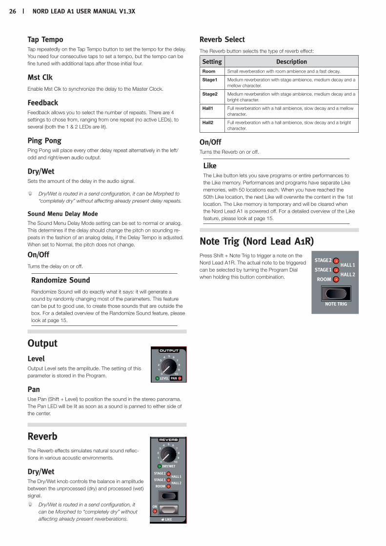
26 | nordleada1UserManUalv1.3x
Tap TempoTap repeatedly on the Tap Tempo button to set the tempo for the delay. You need four consecutive taps to set a tempo, but the tempo can be fine tuned with additional taps after those initial four.
Mst ClkEnable Mst Clk to synchronize the delay to the Master Clock.
FeedbackFeedback allows you to select the number of repeats. There are 4 settings to chose from, ranging from one repeat (no active LEDs), to several (both the 1 & 2 LEDs are lit).
Ping PongPing Pong will place every other delay repeat alternatively in the left/odd and right/even audio output.
Dry/WetSets the amount of the delay in the audio signal.
Dry/Wet is routed in a send configuration, it can be Morphed to “completely dry” without affecting already present delay repeats.
Sound Menu Delay ModeThe Sound Menu Delay Mode setting can be set to normal or analog. This determines if the delay should change the pitch on sounding re-peats in the fashion of an analog delay, if the Delay Tempo is adjusted. When set to Normal, the pitch does not change.
On/OffTurns the delay on or off.
Randomize SoundRandomize Sound will do exactly what it says: it will generate a sound by randomly changing most of the parameters. This feature can be put to good use, to create those sounds that are outside the box. For a detailed overview of the Randomize Sound feature, please look at page 15.
Output LevelOutput Level sets the amplitude. The setting of this parameter is stored in the Program.
PanUse Pan (Shift + Level) to position the sound in the stereo panorama. The Pan LED will be lit as soon as a sound is panned to either side of the center.
Reverb The Reverb effects simulates natural sound reflec-tions in various acoustic environments.
Dry/WetThe Dry/Wet knob controls the balance in amplitude between the unprocessed (dry) and processed (wet) signal.
Dry/Wet is routed in a send configuration, it can be Morphed to “completely dry” without affecting already present reverberations.
Reverb SelectThe Reverb button selects the type of reverb effect:
Setting DescriptionRoom Small reverberation with room ambience and a fast decay.
Stage1 Medium reverberation with stage ambience, medium decay and a mellow character.
Stage2 Medium reverberation with stage ambience, medium decay and a bright character.
Hall1 Full reverberation with a hall ambience, slow decay and a mellow character.
Hall2 Full reverberation with a hall ambience, slow decay and a bright character.
On/OffTurns the Reverb on or off.
LikeThe Like button lets you save programs or entire performances to the Like memory. Performances and programs have separate Like memories, with 50 locations each. When you have reached the 50th Like location, the next Like will overwrite the content in the 1st location. The Like memory is temporary and will be cleared when the Nord Lead A1 is powered off. For a detailed overview of the Like feature, please look at page 15.
Note Trig (Nord Lead A1R) Press Shift + Note Trig to trigger a note on the Nord Lead A1R. The actual note to be triggered can be selected by turning the Program Dial when holding this button combination.
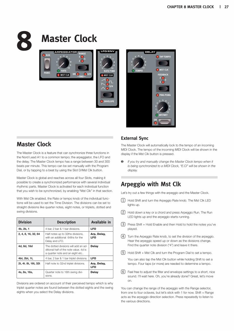
Chapter8MasterCloCk | 27
Master ClockThe Master Clock is a feature that can synchronize three functions in the Nord Lead A1 to a common tempo; the arpeggiator, the LFO and the delay. The Master Clock tempo has a range between 30 and 300 beats per minute. This tempo can be set manually with the Program Dial, or by tapping to a beat by using the Slot D/Mst Clk button.
Master Clock is global and reaches across all four Slots, making it possible to create a synchronized performance with several individual rhythmic parts. Master Clock is activated for each individual function that you wish to be synchronized, by enabling “Mst Clk” in that section.
With Mst Clk enabled, the Rate or tempo knob of the individual func-tions will be used to set the Time Division. The divisions can be set to straight divisions like quarter notes, eight notes, or triplets, dotted and swing divisions.
Division Description Available in
4b, 2b, 1 4 bar, 2 bar & 1 bar divisions. LFO
2, 4, 8, 16, 32, 64 Half notes up to 32ths divisions, with an additional 64ths for the Delay and LFO.
Arp, Delay, LFO
4d, 8d, 16d The dotted divisions will add an ad-ditional half of the note value. 4d is a quarter note and an eight etc..
Delay
4bt, 2bt, 1t, 4 bar, 2 bar & 1 bar triplet divisions. LFO
2t, 4t. 8t, 16t, 32t Half note to 32nd triplet divisions. Arp, Delay, LFO
4s, 8s, 16s, Quarter note to 16th swing divi-sions.
Delay
Divisions are ordered on account of their perceived tempo which is why triplet quarter notes are found between the dotted eights and the swing eights when you select the Delay divisions.
External SyncThe Master Clock will automatically lock to the tempo of an incoming MIDI Clock. The tempo of the incoming MIDI Clock will be shown in the display if the Mst Clk button is pressed.
M If you try and manually change the Master Clock tempo when it is being synchronized to a MIDI Clock, “E.Cl” will be shown in the display.
Arpeggio with Mst ClkLet’s try out a few things with the arpeggio and the Master Clock.
1Hold Shift and turn the Arpeggio Rate knob. The Mst Clk LED lights up.
2Hold down a key or a chord and press Arpeggio Run. The Run LED lights up and the arpeggio starts running.
3Press Shift + Hold Enable and then Hold to hold the notes you’ve played.
4Turn the Arpeggio Rate knob, to set the division of the arpeggio. Hear the arpeggio speed up or down as the divisions change. Find the quarter note division (“4”) and leave it there.
5Hold Shift + Mst Clk and turn the Program Dial to set a tempo.
You can also tap the Mst Clk button while holding Shift to set a tempo. Four taps (or more) are needed to determine a tempo.
6Feel free to adjust the filter and envelope settings to a short, nice sound. I’ll wait here. Oh, you’re already done? Great, let’s move on.
You can change the range of the arpeggio with the Range selector, from one to four octaves, but let’s stick with 1 for now. Shift + Range acts as the arpeggio direction selection. Press repeatedly to listen to the various directions.
8Master Clock

28 | Nordleada1UserMaNUalv1.3x
Synced Delay repeatsKeep the arpeggio running and we’ll add more things.
1Turn both Delay knobs (Tempo & Dry/Wet) fully counterclockwise, press Feedback to light up the “1” LED.
2Turn on the Delay, hold Shift and press the Delay Tap Tempo but-ton to enable the Master Clock for the delay.
3Turn the Delay tempo knob to select the Master Clock “8d” divi-sion and turn up the Dry/Wet mix until you hear the delay repeats.
The arpeggio will play quarter notes, and the delay repeats will be dot-ted eight notes (the first repeat will “move” the following repeats by half an 1/8 note).
Sync the LFO4Let’s add a synchronized LFO sweep. Enable the LFO Master
Clock sync by holding Shift and turning the LFO Rate/Time knob.
5Select the Triangle waveform.
6Have the LFO modulate the filter by turning up the Filter LFO Mod Amount knob a bit
7Turn the LFO rate to select “2b” (2 bars) and turn up the Filter LFO Amount knob a bit close to the 12 o’clock position. If the LFO Amount doesn’t seem to do anything, try closing the Filter Frequency a bit.
There are now quarter notes playing from the arpeggiator, with delay repeats that are synced to dotted 8 notes, and the LFO that opens up the filter once every 2 bars.
8Hold the Mst Clk button and turn the Program Dial. The tempo changes and the three rhythmic things we have running in this example all change simultaneously to reflect the new tempo.
M A tempo setting will be stored in a performance.
Across the SlotsThere is one Master Clock tempo for each performance. All Slots can be in perfect sync with each other.
Sound Menu Kbd SyncThe Sound Menu setting “Mst Clk Kbd Sync” determines if the Master Clock should be reset when you press a key. This type of reset can have a hard or a soft behavior, the softer would allow for note changes slightly ahead of the beat. The Kbd Sync feature can also be turned off, letting the Master Clock run free.

9 Nord Sound Manager
Nord Sound Manager is a free application that allows you to organize the various memory areas, the partitions in the Nord Lead A1. It is also used to download performances or programs to the Nord Lead A1 or to upload any of these items from the Nord Lead A1 memory to the computer hard drive. The Nord Sound Manager provides access to various methods to download the sounds to the Lead A1 and a function to backup and restore the entire Nord Lead A1 memory.
The Nord Sound Manager, the Manager User Manual and USB drivers and instructions on how to install these are available at the www.nordkeyboards.com website in the Download area.
System requirementsThe Nord Sound Manager is compatible with computers running Mac OSX 10.4 or later, Windows XP, Vista, Windows 7 and Windows 8. If you run the Nord Sound Manager on a Windows computer, you also need a Clavia USB Driver of version 3.02 or later installed. This driver will be automati-cally installed by the Sound Manager Setup application.
Chapter 9 Nord SouNd MaNager | 29
System Menu
1 - Memory ProtectThe Memory Protect setting determines if Programs and Performances can be stored to the Nord Lead A1 memory or not. The setting is On when the Nord Lead A1 leaves the factory.
M System, MIDI and Sound menu settings are not protected.
Range: On (default), off
2 - TransposeThis setting can transpose the pitch of the Nord Lead A1 up or down in semitone steps.
M The MIDI output will not be transposed.
Range: -/+ 6 semitones (default = 0).
3 - Fine TuneThis setting fine tunes the pitch of the Nord Lead A1.
Range: -/+ 50 cent (default = 0).
4 - Sustain Pedal PolarityChange the polarity of a connected sustain pedal, in case the func-tionality of the pedal is reversed. The Auto setting will determine what polarity a connected pedal has.
Range: Auto (default), CL - Close, OP - Open.
5 - Wheel ModeThe Modulation Wheel can be set to control both Morph and Vibrato, or as an exclusive Vibrato control.
Range: L1 Morph + Vibrato (default), L2 Vibrato.
6 - Ctrl Pedal ModeA connected Control pedal can be used to control the Nord Lead A1 volume or as a Morph Controller.
Range: P1 Volume (default), P2 Morph.
7 - Ctrl Pedal TypeDifferent models of control pedals have different specifications (resis-tance, offset and linearity). The most commonly used pedals are pre-configured in the Nord Lead A1, select the type you use.
Range: R5 (Roland EV-5, default) , R7 (Roland EV-7), Y7 (Yamaha FC-7), K0 (Korg EXP-2 & XVP-10), Ft (Fatar & Studiologic VP/25)
8 - Ctrl Pedal GainAdd some gain to the output of a connected Control pedal if it does not reach the maximum level. Operating a connected control pedal will display the output level from 0 to 100.
Range: 1 - 10 (default 1).
9 - Mutator ProtectWhen Mutator Protect is On, you need to confirm your intentions by pressing Execute before the actual Mutate Sound or Randomize Sound takes place.
Range: On, Off (default)
A B C D - Slot Output RoutingRoute the Slots to the audio outputs of the Nord Lead A1. Slots can be routed to output pairs (1-2 and 3-4), or single outputs.
E Outputs 1 & 2 are routed to the headphones.
Ranges: 12 (default), 34, 1, 2, 3, 4.
10 The Menus
Any settings that you change in the System, MIDI or Sound menu will take immediate effect on a global basis, and will be stored until you change them the next time. Enter the menus by pressing and holding Shift and the System, MIDI or Sound button (Slot A - C buttons). The A-C LED above the buttons will turn yellow and start blinking. Select a function by turning the Program Dial and change the setting by holding Shift and turn the Program Dial at the same time. Exit the menus by pressing a second time on any Slot button.
30 | Nord Lead a1 User MaNUaL os v1.3x
MIDI Menu
G - Global MIDI ChannelThe Global MIDI Channel transmits all keyboard, pedal and panel ac-tions. It can also be used as a receiving channel.
Range: 1 - 16, Off (default = 1).
A, B, B, D - Slot MIDI ChannelSet individual MIDI Channels for the Slots when they should respond to MIDI events on certain incoming MIDI Channels.
Range: 1 - 16, Off (default A = off, B =off C = off, D = off).
t - Soft Thru MIDI ChannelIncoming MIDI note on/off data that is received at either the 5-pin or the USB MIDI on the Soft Thru Channel, will be re-routed to the 5-pin MIDI OUT connector.
Range: 1 - 16, Off (default = 10).
1 - Local ControlLocal disables or enables the connection between the keyboard and panel and the actual Lead A1 synthesizer. Local On is the default setting. Local Off is useful when a external sequencer is used and the keyboard and panel is only used to transmit MIDI, which the sequencer then routes back to the synthesizer.
Range: On (default), Off
M Local defaults back to On every time the Nord Lead A1 is pow-ered on.
2 - Control Change (CC) ModeControl Change Mode specifies how the front panel’s knobs and but-tons are handled in the MIDI communication with MIDI Control Change messages. The options are either send or receive, or both, or if these messages should be ignored.
Range: Sr (send & receive - default), r (receive only), S (send only), Off
3 - Program Change ModeProgram Change Mode specifies how the Nord Lead A1 handles MIDI Program Change messages.
Range: Sr (send & receive - default), r (receive only), S (send only), Off
4 - Pitch Bend ModePitch Bend Mode specifies how the Nord Lead A1 handles the Pitch Bend stick and incoming pitch bend MIDI messages.
Range: Sr (send & receive - default), r (receive only), S (send only), Off
5 - Send CC Dump all Program parameters of the currently focused Program as MIDI Control Change messages. Press Execute to begin the transmis-sion.
6 - Dump OneDump One makes a MIDI System Exclusive transmission of all the parameters of the currently active Program or Performance. Press Execute to begin the transmission.
7 - Dump Program BankDump Program Bank makes a MIDI System Exclusive transmission of all the parameters, for all of the 99 Programs or Performances in the current Bank. Press Execute to begin the transmission.
In the MIDI chapter on page 33, there is a description on how the Nord Lead A1 receives a Sys Ex dump.
Sound Menu
1 - Mst Clk Kbd SyncMaster Clock Keyboard Sync On will reset the Master Clock when a key is played. The Soft option is a more gentle approach, depending on when in the beat, the key is played.
Range: Off, SF (Soft, default), On.
2 - Delay ModeDelay Mode Analog will change the pitch on sounding repeats, when the Tempo is adjusted with the Delay Tempo knob. When set to Nor-mal, the pitch will not change.
Range: nO (Normal), An (Analog = default).
3 - Vibrato Rate The rate of the Vibrato.
Range: 4.00 - 8.00 Hz (default = 6 Hz).
4 - Vibrato AmountThe amount of the Vibrato when the delayed vibrato modes are used.
Range: 0 - 50 cent (default = 12 cent).
Chapter 10 the MeNUs | 31

32 | Nord Lead a1 User MaNUaL v1.3x
Nord Lead A1 MIDI operationThe Nord Lead A1 is designed to be very flexible in a MIDI setup. You can use it as a keyboard to control its internal sounds and other hardware or software sound sources. It can also be used as a set of individual sound engines to be played/controlled by external MIDI units such as a sequencer.
There are two fundamental methods of operation when using the Nord Lead A1 in a MIDI setup. You can use the Global MIDI Channel or individual Slot MIDI Channels. These methods differs a little bit in their flexibility and in what you can achieve.
Lead A1 MIDI IN MIDI OUT
Global MIDI a aSlot MIDI a
Keys you play on a Nord Lead A1 keyboard, and any tweaks that you do on the Lead A1 panel will generate MIDI messages on the Global Channel.
A Slot MIDI Channel is only receiving MIDI messages.
M Whenever the text in this manual refers to a “keyboard”, the mean-ing in the description is also relevant for a external MIDI controller.
MIDI SettingsMIDI Channel selections, settings on how the Lead A1 should handle Program Change, Pitch Bend, Control Change messages and other MIDI related settings are made in the MIDI Menu.
Global MIDI ChannelBy using the Global MIDI Channel, all MIDI notes and Control Change messages can be transmitted and/or received on a single MIDI chan-nel.
MIDI that enters the Nord Lead A1 on the Global MIDI channel will play all the Slots that are active. If a Performance includes layers and/or splits, or actions with the Morph controls, those aspects will be repro-duced in the same way as if you played on the keyboard itself.
Slot MIDI ChannelsBy using the individual Slot MIDI Channels in the Nord Lead A1, you have individual control of the Slots, for notes as well as for parameters. This can for example be used as a multitimbral setup, controlling 4 individual sound sources from a sequencer.
E A Slot does not have to be active in a Performance, it will always respond to incoming MIDI on its MIDI Channel. This makes it pos-sible to control selected Slots from the keyboard, and other Slots from other external sources.
Sequencing: Global MIDI ChannelConnect the Nord Lead USB connection (or the 5-pin MIDI In and Out) to a computer/MIDI interface/sequencer. Set the sequencer track to all Channels or MIDI Channel 1, which is the default Global MIDI channel in the Nord Lead A1.
Play on the keyboard and record the performance. Any controllers that you use – Morphs, pedals etc. – will also be transmitted as MIDI messages.
Recording parameter changesThere are more parameters available in the Nord Lead A1 Slots than there are available MIDI Control Change numbers. This means that the Slot buttons on the panel will be used to set the transmitting and receiving Slot focus of panel generated CC messages. This allows you to record and receive parameter changes on the Global MIDI Channel.
If you want to make parameter changes on more than one Nord Lead A1 Slot at the same time, the Slot MIDI Channel approach will be more suitable.
Sequencing: Slot MIDI ChannelsProgram or record the notes to tracks in the sequencer, tracks that are set to the Slot MIDI Channels. Keyboard and panel actions from the Nord Lead A1 will be transmitted on the Global MIDI Channel. Local may be turned Off, to avoid double triggered sounds.
Overdub tracks to record any parameter changes by making these on the Nord Lead A1 panel, or from other MIDI devices set to control the Nord Lead A1.
Continue with the next track, set to another Slot’s MIDI Channel.
Slot C & D
Slot A & B
Slot C & D
Slot A & B
11 MIDI

Chapter 11 MIdI | 33
Control Slots with another keyboardUse a Performance with some of the Slots controlled from the Lead A1 itself and other Slots from an external keyboard or sequencer, set to corresponding Slot MIDI channel(s). Active Slots will be controlled from the A1 keyboard, inactive Slots are controlled from external units.
Message types
Program Changes and Bank SelectProgram Change messages are transmitted on the Global MIDI chan-nel and are recognized on the Global and/or the Slot MIDI Channels. Bank Select messages (CC00, CC32) are used to select the 8 program banks (CC00, value 0 + CC32 values 0-7) or the 4 performance banks (CC00, value 0 + CC32, value 0-3) when Performance Mode is active. Bank Select messages should be immediately followed by a Program Change message when you wish to select a bank from an external unit.
The Slots will respond to incoming Program Change messages on their individual Slot MIDI Channels.
Incoming Program Change messages on the Global MIDI Channel will change the performance, if Performance Mode is enabled.
M Incoming Program Change on the Global MIDI Channel will change programs on the focused Slot if Performance Mode is not enabled.
If you do not want the Nord Lead A1 to transmit or respond to Program Change messages, this can be turned off in the MIDI Menu.
Control Change messagesMost of the parameters on the Nord Lead A1 panel will generate a CC message if operated, and the reception of these messages will change the parameter accordingly. A full list of the parameters and their Control Change number is on page 34.
If you do not want the Nord Lead A1 to transmit or respond to Control Change messages, this can be turned off in the MIDI Menu.
Pedal Control ChangeA Control pedal transmits CC7 if it is set to volume in the System Menu and CC11 if is set to be a Morph source. The sustain pedal transmits CC64.
VolumeThe output level of an Performance or an individual Slot can be set by transmitting CC7 to the Nord Lead A1 on the Global, or any of the Slot MIDI Channels.
Pan CCThe position of an Performance or a individual Slot in the stereo pan-orama can be set by transmitting CC10 to the Nord Lead A1 on the Global Channel, or any of the Slot MIDI Channels.
MIDI LocalIf a sequencer is set to echo back incoming MIDI data, this can cause double triggered notes if the Nord Lead A1 keyboard is used. If this occurs, set MIDI Local to Off.
MIDI ThruA Soft Thru Channel can be set in the MIDI Menu. By doing this, in-coming note messages on that channel from the USB MIDI or the 5-pin MIDI Input, will be re-routed through the 5-pin MIDI Out connector.
MIDI ClockThe Nord Lead A1 Master Clock will automatically sync to incoming MIDI Clock.
M The Nord Lead A1 does not transmit MIDI Clock messages. If you want to synchronize several units including the Nord Lead A1, an external MIDI Clock source should be used.
USB MIDIIf you use a computer running Windows XP, Vista, Windows 7 or Windows 8, install the Nord v3.x USB driver to be able to use the MIDI via USB functionality. This driver is available through Windows Update by just connecting the computer to the Internet with the Nord Lead A1 connected at one of the USB ports. The USB driver can also be downloaded from the www.nordkeyboards.com website.
M Computers running Mac OSX have a native USB MIDI support for the Nord units. No driver installation is necessary.
Panic If notes get stuck during a performance, press Panic. This will reset incoming CC messages and send an All Notes Off message to all Slots.
MIDI Dumps
Transmit settingsComplete Program and Performance settings can be transmitted through MIDI as Controller Change or System Exclusive messages. The transmissions are executed in the MIDI Menu. A Control Change transmission contains the settings of the single Program in focus and can be used to initialize a sequencer track with Program parameters. Use System Exclusive to store a Program or a complete Performance on a computer or in a sequencer. A System Exclusive transmission can also contain all the Programs or Performances in a Bank.
Receive Programs or BanksMake sure that the MIDI Channel on the transmitting device matches the Global (or Slot) MIDI Channel on the Nord Lead A1 and start the transmission on the computer/sequencer. Single Programs will be placed in the Nord Lead A1 edit buffer, you need to Store these if you want to keep them. The currently active Program Bank in the Nord Lead A1 will be over-written if a System Exclusive package of a complete Bank is received.
Slot C & D
Slot A & B

34 | Nord Lead a1 User MaNUaL v1.3x
MIDI Controller listThese are the MIDI Control Change numbers used for the Nord Lead A1 parameters.
•Buttons that control “on/off” functions have a Controller value of “0” at the “off” position and a value of “127” at the “on” position.
•Buttons that step through various possibilities start with a Controller value of “0” for the “lowest” setting and then increment for each step upwards. The size of the increments depends on how many possible settings there are.
Nord Lead A1 parameter MIDI CCArp Run 90
Arp Tempo/Clk Divisions 9
Arp Master Clock Enable 86
Arp Range 88
Arp Direction 89
Glide Rate 5
Mono Selector 15
Voice Mode Unison 16
Pitch Bend Range 118
Vibrato Select 56
LFO Rate/Clk Divisions 19
LFO Waveform Selector 20
LFO Master Clock Enable 2
LFO Envelope Selector 34
Mod Envelope Attack 26
Mod Envelope Decay/Sustain 27
Mod Envelope Release 28
Mod Envelope Invert 38
Mod Envelope Velocity 29
Osc LFO Modulation Amount 68
Osc Mod Envelope Amount 69
Osc Control 31
Osc Waveform Selector 30
Osc Configuration 33
Filter LFO Modulation Amount 48
Filter Mod Envelope Amount 43
Filter Frequency 74
Filter Type 44
Filter Keyboard Tracking 46
Filter Drive 47
Filter Resonance 42
Amp Envelope Attack 73
Amp Envelope Decay 36
Amp Envelope Release 72
Amp Envelope Velocity 35
FX Amount 55
FX Selection 53
FX On/Off 52
Delay Tempo/Clk Divisions 78
Delay Master Clock Enable 51
Delay Feedback 79
Delay Ping Pong 100
Delay Amount 76
Delay On/Off 99
Output Level 71
Nord Lead A1 parameter MIDI CCPan 10
Reverb Amount 98
Reverb Selector 96
Reverb On/Off 97
Octave Shift 17
Hold 58
Hold Enable 54
Slot Focus 119
Slot Enable 115
Volume Pedal (transmits if enabled as Volume in System menu)
7
Ctrl Pedal (transmits if enabled as Morph in System menu) 11
Mod Wheel 1
Wheel/Pedal Morph (incoming CC) 11
Sustain Pedal 64
Bank Select MSB 0
Bank Select LSB 32

Chapter 11 MIdI | 35
MIDI Implementation Chart
Function Transmitted Recognized RemarksBasic ChannelDefault Channel
1 - 161 - 16
1 - 161 - 16
Indiv. channels for Slot A, B, C & D
Mode Default Message Altered
Mode 1, 3X***************
Mode 1, 3X
NoteNumber True Voice
0-127 0-127
Velocity Note ON Note Off
O, v= 1 - 127X
O, v= 1 - 127X
After Key’sTouch Channel
XX
XX
Pitch Bender O O
Control Change O O See MIDI CC on page 34
Program Change True#
O, 0-98 O, 0-98 Bank Sel: CC00, CC32
System Exclusive O O
System Song PosCommon Song Sel Tune
X X X
X X X
System ClockRealtime Commands
XX
O
Aux Local on/offMessage All notes off Active Sense Reset
Number True Voice
Mode 1: Omni On, Poly - Mode 2: Omni O, Mono - Mode 3: Omni Off, Poly - Mode 4: Omni Off, Mono - O = Yes - X = No

36 | Nord Lead a1 User MaNUaL v1.3x
SpecificationsGeneral
•49-keyoctavevelocitysensitivekeyboardwithoctaveshiftbuttons(+/-2octaves).
•26voices.
•KeyboardSplitwith2slotsfortheupperandlowersections.
•ModulationWheel(keyboardversiononly).
•PitchStickwithnodeadzoneatzerocrossing(keyboardversiononly).
•ProgrammablePitchbendrange,upto+/-4octaves.
•Separateup/downbendrange:+2semitones,-12or-24semi-tones.
•1pedalinputforsustainpedal.
•1pedalinputforexpressionpedal.
User Interface
•3LEDdisplays,23knobs,3encodersand20+buttonsforprogramandperformanceediting.
Oscillator Section
•Oscillatormodelsofmultiplewaveforms(traditionalanalog,extendedanalog,pulsewaveforms,digitalwaveforms)
•OscillatorConfigurations:8categories(pitch,detune,shape,sync,amplitudemodulation,noise,mixconfigurations,FM)
Filter Section
•Multi-modefilterwith12dB/Oct(2-pole)lowpass,24dB/Oct(4-pole)lowpassandbandpass,highpass,LadderMandLadderTBcharacteristics.
•Cutoff,Resonance,envelopeamount,envelopeamountcontrolledbyvelocity.
•Filterkeyboardtrackingcanbesettooff,1/3,2/3or1:1.
•AdjustableFilterDistortion.
Modulation Section
•LFOgeneratesatriangle,square,sawtoothorsampleandholdwaveforms.LFOcanberoutedtoFilterFrequency,andOscillatorModulation.TheLFOratecanbesynchronizedtotheMasterClock.
•LFOcanbeswitchedtoEnvmodewithfourdifferentcharacteris-ticsandasampleandholdgeneratorthatismanuallytriggeredbykeyboard.
•Arpeggiator:Range:1-4octaves.Modes:up,down,up/down,random.TheArpeggioratecanbesynchronizedtotheMasterClock.
•ADR/ASRenvelope,velocitycontrolon/off,inverseenvelopeon/off.
Amplifier Section
•ADR/ASRenvelope,velocitycontrolon/off,gaincontrol.
•Individualpanningperprogram
Performance Section
•Voicemodes:Poly,LegatoandMonowithGlide,TrueUnison1,2&3.
•Fourprogramslotsforlayeringpossibilities.
•Effects.
•FXsectionwithFlanger,Phaser,RingModulation,Chorus,EnsembleandDrive.
•Delaysectionwithtaptempo,fourstagesoffeedback,ping-pong,dry/wetmix.TheDelaytempocanbesynchronizedtotheMasterClock.
•Reverbsectionwithfivealgorithms(Room,Stage1,Stage2,Hall1,Hall2).
Memory
•Programs(singlesounds):8x50(400)locations.
•Performances(multisounds):4x50(200)locations.
Audio Out
•4outputs.Eachslotcanbeassignedtoitsownoutput.
•Headphonesoutput.
•Highresolutionlownoise24bitDACs.
MIDI Features
•Allcontrolknobsandswitchessendandreceivecontrolchangemessages.
•Systemexclusivebulkdumps.Oneprogramorallprograms.
•MasterClockwillsynctoincomingMIDIclock.
•SoftThru.
Connections
•4LineLevelAudioOutputs-¼",6,35mmjacks,unbalanced.
•StereoHeadphoneOutput-¼",6,35mmstereojack.
•SustainPedal-¼",6,35mmjack.Useamomentarypedal,likee.g.,RolandDP-2,DP-6,YamahaFC-4,FC-5,FatarVFP1-25etc.
•ControlPedal-¼",6,35mmTRSstereojack.UseaYamahaFC-7,RolandEV-7,RolandEV-5,KorgEXP2orKorgXVP10.
•USBconnectorwithMIDIcapabilities.
•MIDIIn&Out-5pinDINconnectors.
Included Accessories
•UserManual.
•PowerCordwithIECC14connector.
•RackEars(NordLeadA1Ronly).
Dimensions
•NordLeadA1:802x92x260mm(31.5x3.6x10.2").
•NordLeadA1R:466x115x169mm(18.3x4.5x6.6").
Weight
•NordLeadA1:4.85kg(10.7lbs).
•NordLeadA1R:3,35kg,6.6lbs.
12 Appendix

Chapter 12 appeNdix | 37
Display Messages
Message Description
Storing
Pro MemoryProtected.
Mst Clk Tempo
E.Cl MasterClockissynchronizedtoexternalMIDClock,tempocannotbemanuallysetontheNordLeadA1.
Mutator, Randomize, Init Sound
nvt PressExecutetoMutateSound.
rnd PressExecutetoRandomizeSound.
Ini PressExecutetoInitSound.
O Mutate/Random/Initprocessexecuted
Copy and Paste related
CP.x CopySlot,wherexisa,b,corD.
PS.x PastingacopiedSlottoadestinationSlot(a,b,corD).
CPY CopyVelocity/WheelMorph.
PSt PastingaVelocity/WheelMorph.
5.0 Copy(andPaste)asettingwithvalue5.0(0.0-10.0).
MIDI System Exclusive transfers
E.sv Read/WriteError.
E.si SizeError.
E.ve VersionError.
E.Ch CheckSumError.
Pro MemoryProtected.

38 | Nord Lead a1 User MaNUaL v1.3x
13 Index
Index
AAmp Env 23Amplitude Modulation 23Arpeggio 19Arpeggio directions 19Arpeggio range 19Attack 23Audio Connections 37
BBand Pass 25Bend Range 19
CControl Change Mode 31Control Pedal 8Control Pedal Mode 30Control Pedal Type 30Copy 17Ctrl Pedal Gain 30
DDecay 23Delay
Feedback 26On/Off 26
Delay Mode 31Detune Configuration 22Dial 17Display 17Dly1 19Dry/Wet
Reverb 26Dump One 31Dump Program Bank 31
EEnv 20Envelope 20Envelope Amount 24Env Vel 21Execute 17Expression pedal 8
FFeedback 26Filter 24
Drive 24Frequency 24Resonance 24
Fine Tune 30Focus 9Freq 24Frequency Modulation 23
GGlide 19Global Channel 31
HHeadphones 8High Pass 25Hold 18Hold Enable 18
IInit Sound 19Inv Env 21
KKbd Sync 31KB Track 24Keyboard Octave Shift 18Keyboard Tracking 24
LLayer 9LED Display 17Legato 19Level 26LFO
Rate 20Waveform Selector 20
Like 26Local 31Low Pass 24
MMaster Clock 27Master Level 17Memory Protect 30MIDI
Connections 8Controller 34LED 17
MIDI Channel 31MIDI Menu 31Mixed Configurations 23Mod Env 20Modulation Envelope 20Mod Wheel 19Monitor 17Mono 19Morph
Mode 14Range 14
Morph destinations 13Morphing 13Morph Latch 14Mst Clk 19, 20, 26Multi Focus 18Mutate Morph 15Mutate Sound 25Mutator 15
NNoise 22Note Trig 26
OOctave Shift 18Osc Config 22Osc Ctrl 22Oscillator 21Oscillator Configuration 22Output 26
Connections 8Output Routing 30
PPan 26Panic 19Paste 17Pedal Connections 8Performance Mode 17Ping Pong 26Pitch 22Pitch Bend Mode 31Program Change 31Program Dial 17
RRandomize 15Randomize Sound 26Release 23Run 19
SSelector buttons 7Send CC 31S/H 20Shape 22Shift 18Slot Channel 31Slot Output 30Slots 9, 18Soft Thru 31Specifications 36Split 10, 18Store Button 17Storing 9Sustain Pedal 8, 30Sync Configuration 22System Menu 30
TTap Tempo 26Transpose 30Type 24
UUnison 19USB Connection 8
VVelocity 13Vibrato Amount 31Vibrato Rate 31Voice Mode 19
WWave 21Wheel 13
FCC Information (U.S.A.)1. IMPORTANT NOTICE: DO NOT MODIFY THIS UNIT!
This product, when installed as indicated in the instructions contained in this manual, meets FCC requirements. Modifications not expressly approved by Clavia may void your authority, granted by the FCC, to use the product.
2. IMPORTANT: When connecting this product to accessories and/ or another product use only high quality shielded cables. Cable/s supplied with this product MUST be used. Follow all installation instructions. Failure to follow instructions could void your FCC authorization to use this product in the USA.
3. Note: This equipment has been tested and found to comply with the limits for a Class B digital device, pursuant to Part 15 of the FCC Rules. These limits are designed to provide reasonable protection against harmful interference in a residential installa-tion. This equipment generates, uses, and can radiate radio frequency energy and, if not installed and used in accordance with the instructions, may cause harmful interference to radio communications. However, there is no guarantee that interference will not occur in a particular installation. If this equipment is found to be the source of interference to radio or television reception, which can be determined by turning the equipment off and on, the user is encouraged to try to correct the interference by one or more of the following measures:
– Reorient or relocate the receiving antenna.
– Increase the separation between the equipment and receiver.
– Connect the equipment into an outlet on a circuit different from that to which the receiver is connected.
– Consult the dealer or an experienced radio/TV technician for help.
This device complies with Part 15 of the FCC Rules. Operation is subject to the following two conditions:
(1) this device may not cause harmful interference, and
(2) this device must accept any interference received, including interference that may cause undesired operation.
Unauthorized changes or modification to this system can void the users authority to operate this equipment.
This equipment requires shielded interface cables in order to meet FCC class B Limit.
For Canada
NOTICEThis Class B - digital apparatus complies with Canadian ICES-003.
AVISCet appareil numérique de la classe B - est conforme à la norme NMB-003 du Canada.
DECLARATION OF CONFORMITY Compliance Information Statement
Model Name: Nord Lead A1, Nord Lead A1R
Type of Equipment: Digital Synthesizer
Responsible Party: Clavia DMI AB
Address: P.O. BOX 4214. SE-102 65 Stockholm Sweden
Telephone: +46-8-442 73 60
