no slide titleams-oulu.com/wp-content/uploads/2014/03/dcp100-introduction.pdf · • … used to...
TRANSCRIPT
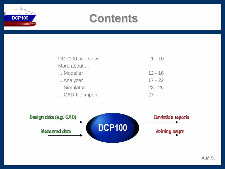
Contents
DCP100 overview 1 - 10
More about ...
... Modeller 12 - 16
... Analyzer 17 - 22
... Simulator 23 - 26
... CAD-file import 27
A.M.S.

What is DCP100 ?
DCP100 is…
• … most advanced software developed especially for ship production.
• … used for dimensional analysis and alignment control of steel structures.
• … used to compare measured as-built ship assembly with the design model.
• … used to simulate the alignment and the joining of two ship structures.
A.M.S.
Why to implement DCP100 ?
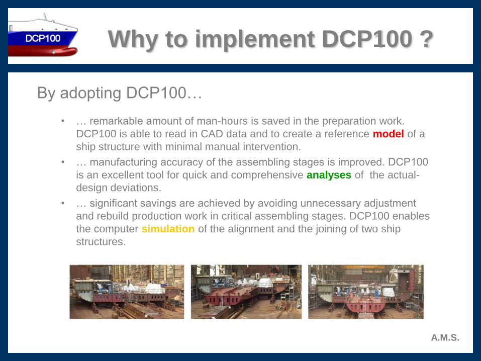
By adopting DCP100…
• … remarkable amount of man-hours is saved in the preparation work.
DCP100 is able to read in CAD data and to create a reference model of a
ship structure with minimal manual intervention.
• … manufacturing accuracy of the assembling stages is improved. DCP100
is an excellent tool for quick and comprehensive analyses of the actual-
design deviations.
• … significant savings are achieved by avoiding unnecessary adjustment
and rebuild production work in critical assembling stages. DCP100 enables
the computer simulation of the alignment and the joining of two ship
structures.
A.M.S.

Why to select DCP100 ?
By purchasing DCP100 you will…
• … accept modern network software. The operation license is not PC-
workstation dependent.
• … receive advanced graphical software. 3D graphical objects are activated
by mouse click. Various menus and displays are immediately at user’s
disposal.
• … get three separate software modules: Modeller for preparation work,
Analyzer for observing dimensional distortions and Simulator for viewing
joining structures. In addition there is Viewer module for 3D viewing of
results.
A.M.S.
How DCP100 modules are
realized?
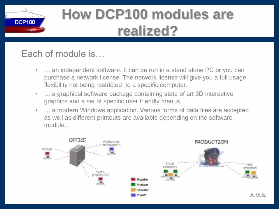
Each of module is…
• … an independent software. It can be run in a stand alone PC or you can
purchase a network license. The network license will give you a full usage
flexibility not being restricted to a specific computer.
• … a graphical software package containing state of art 3D interactive
graphics and a set of specific user friendly menus.
• … a modern Windows application. Various forms of data files are accepted
as well as different printouts are available depending on the software
module.
A.M.S.

What is DCP100 Modeller ?
Modeller is…
• … a specific software which imports directly a CAD file (different formats
available, see more details on slide 27) and exports a reference model (prd
format). The actual production data is compared to this design model.
• … an intelligent model builder which creates the graphical model automatically,
with minimal user intervention. This reference model comprises objects which
are essential for the dimensional control purposes.
• … a CAD tool itself, which can be used to build interactively the design model.
In addition the model can be edited, graphical objects added to it or removed
from it.
A.M.S.
What is DCP100 Analyzer ?
A.M.S.
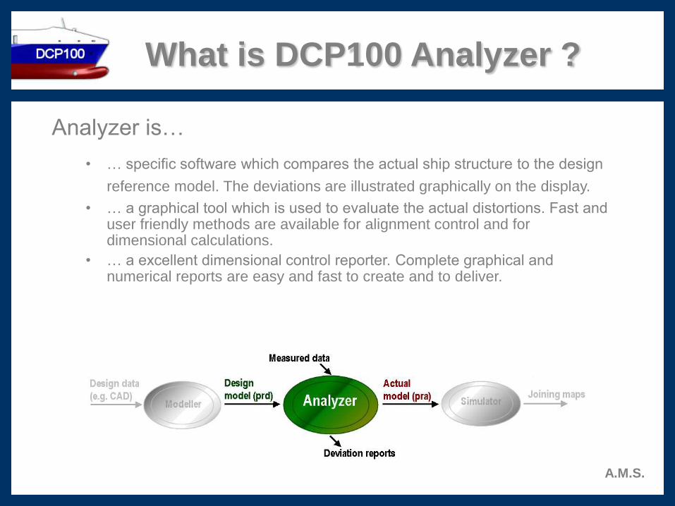
Analyzer is…
• … specific software which compares the actual ship structure to the design
reference model. The deviations are illustrated graphically on the display.
• … a graphical tool which is used to evaluate the actual distortions. Fast and user friendly methods are available for alignment control and for dimensional calculations.
• … a excellent dimensional control reporter. Complete graphical and numerical reports are easy and fast to create and to deliver.

What is DCP100 Simulator ?
A.M.S.
Simulator is…
• … purpose-built software for simulating the alignment and the joining of two adjacent ship structures. The results of the fitting are illustrated graphically on the display.
• … an excellent graphical program to visualize the actual distortions of the joining faces. Proper alignment methods are at user’s disposal to efficiently achieve the best possible merging of the units.
• … production tool to guide the assembling work. Specific graphical and numerical joining maps are available to illustrate the welding gap and the burning map in the case of excess material.

What is DCP100 Viewer ?
A.M.S.
Viewer is…
• … a graphical tool which reads in the actual-design data produced by Analyzer.
• … used for displaying and viewing actual-design deviations.
• … also used to print out the MS Word deviation reports.
Contact information
A.M.S.
Accuracy Management Services Ltd.Paulaharjuntie 22
FIN-90530 Oulu, FINLAND
Phone/Fax:+358 8 547-2369 / -2673
Internet: www.ams-oulu.com
Markku Manninen (President, contact in all matters)
Mobile: +358 40 503 3189
E-mail: [email protected]
Teuvo Heimonen (Technical advisor, contact in technical matters)
Mobile: +358 40 586 8108
E-mail: [email protected]
More about ...
A.M.S.
In the next slides a bit more technical descriptions
of DCP100 are presented. Contents of this section
is as follows:
More about ...
... Modeller 12 - 16
... Analyzer 17 - 22
... Simulator 23 - 26
... CAD-file import 27
More about Modeller
A.M.S.
The Modeller module is used to build up a unit or
extend and update already existing unit.
• The model of a new unit can be built up from scratch using a set of create
and edit type of commands.
• User may import a file which contains a list of points to be measured with
the design coordinate values. Modeller creates automatically the unit
structure based on these design coordinate values.
• User may also import a CAD-file which is created by the yard's CAD/CAM
system to be converted into the format of this program, the prd format.
• In addition a previously defined unit may be opened to be updated or
extended.
• When the user is satisfied with the model of the unit he can save it and then
import it to Analyzer module.
Unit build up from...
A.M.S.
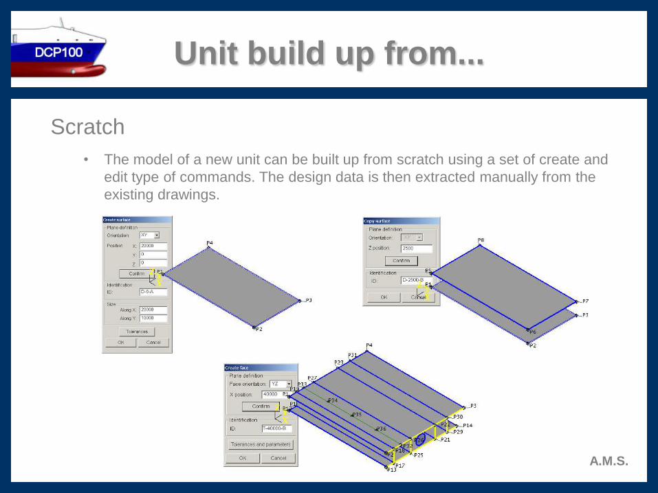
Scratch
• The model of a new unit can be built up from scratch using a set of create and
edit type of commands. The design data is then extracted manually from the
existing drawings.
Unit build up from...
A.M.S.
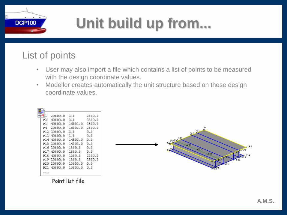
List of points
• User may also import a file which contains a list of points to be measured
with the design coordinate values.
• Modeller creates automatically the unit structure based on these design
coordinate values.

Unit automatically translated to PRD format and
then displayed.
Unit displayed in DXF format.
Unit build up from...
A.M.S.
CAD file
• User may open a CAD file to be converted into the format of this program,
the prd format.
• Software automatically simplifies the model to fit perfectly for dimensional
control purposes.
• The user completes the model and saves it as prd type of file.
Why DCP100 Modeller ?
A.M.S.
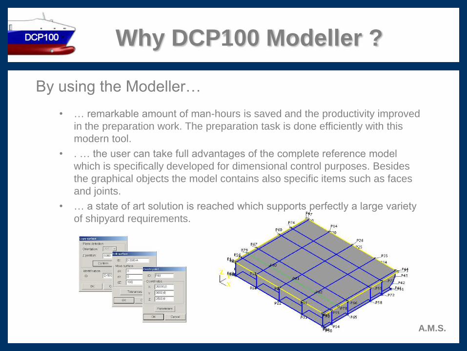
By using the Modeller…
• … remarkable amount of man-hours is saved and the productivity improved
in the preparation work. The preparation task is done efficiently with this
modern tool.
• . … the user can take full advantages of the complete reference model
which is specifically developed for dimensional control purposes. Besides
the graphical objects the model contains also specific items such as faces
and joints.
• … a state of art solution is reached which supports perfectly a large variety
of shipyard requirements.
More about Analyzer
A.M.S.
With the Analyzer module the dimensional accuracy of
a unit is studied.
• The actual coordinate values from the measured points are read from a file
or entered manually.
• The dimensional distortions are presented graphically and numerically.
• Analyzer offers the align control functionality for adjusting the deviations.
• Complete tolerance control allows to show the exceeding values with red
numbers.
• The verification of critical scalar distances is easily calculated with specific
menus.
• MS Word reports are available for delivery or to be shown on the screen
and to be printed out.
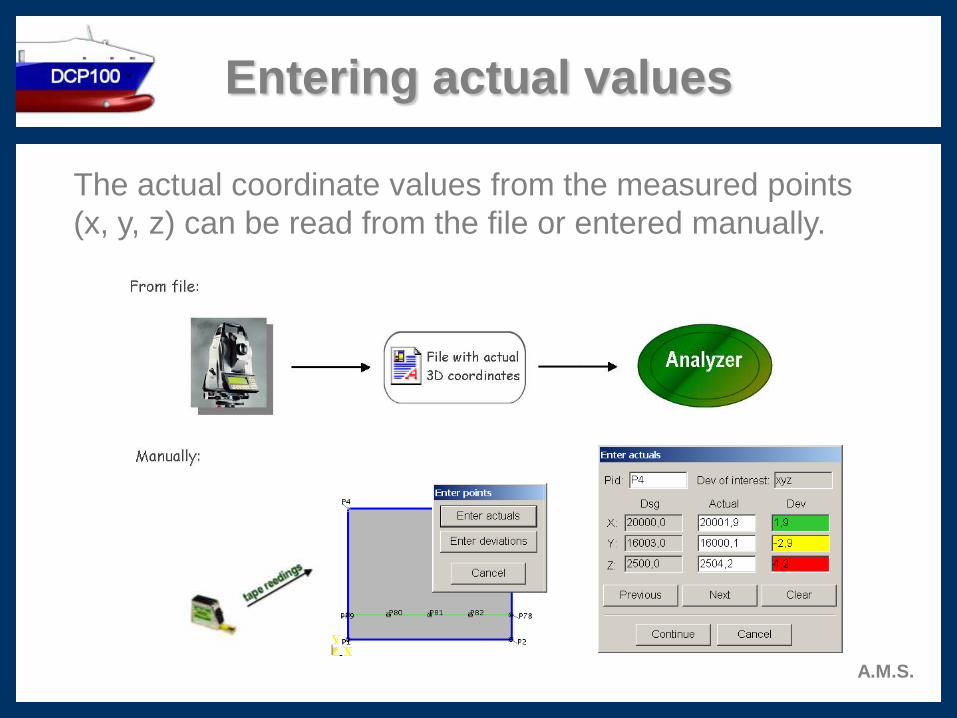
Entering actual values
A.M.S.
The actual coordinate values from the measured points
(x, y, z) can be read from the file or entered manually.
Deviations
A.M.S.
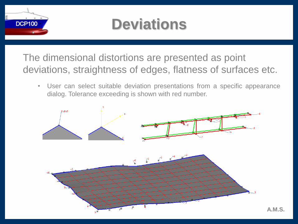
The dimensional distortions are presented as point
deviations, straightness of edges, flatness of surfaces etc.
• User can select suitable deviation presentations from a specific appearance
dialog. Tolerance exceeding is shown with red number.
Aligning
A.M.S.
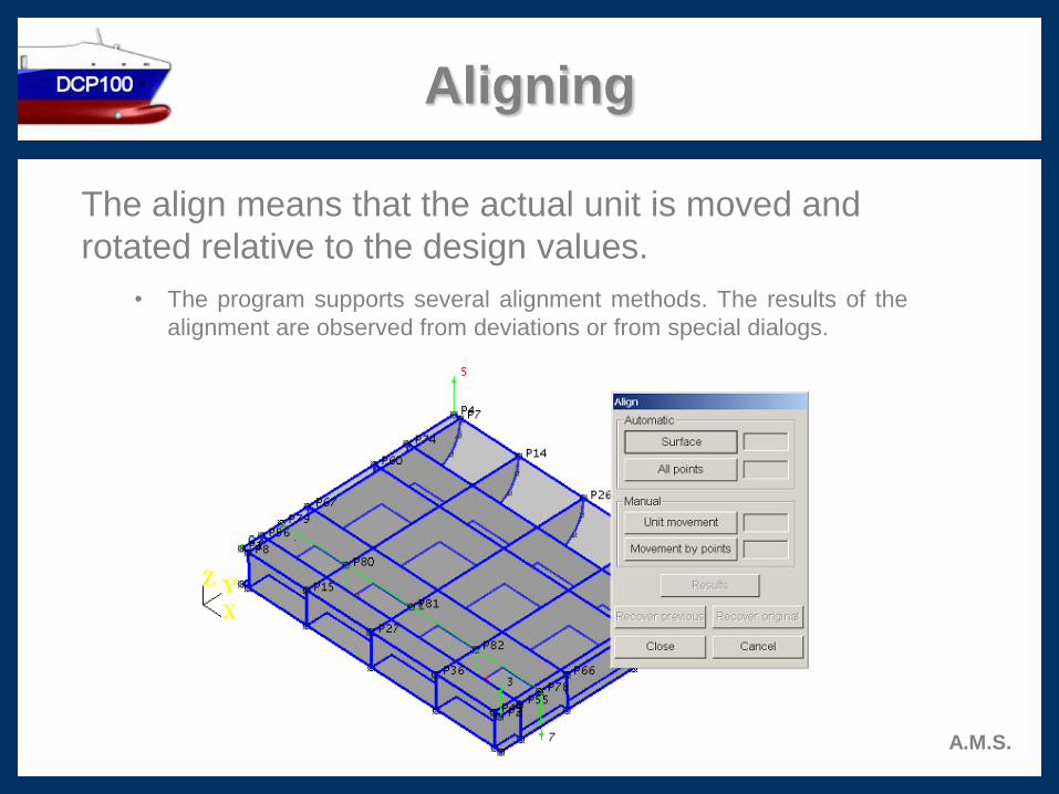
The align means that the actual unit is moved and
rotated relative to the design values.
• The program supports several alignment methods. The results of the
alignment are observed from deviations or from special dialogs.

Reporting
A.M.S.
With the Analyzer user can fast and easily generate MS
Word deviation reports
• The default report consists of Cover page, Point list page(s) and selected
pictures about objects.
• User may create, modify, and use his own report templates.
• User can select all points to be included to the report or select certain object(s)
with a mouse click.
• Reports can be read on the screen, edited, saved, and emailed or printed.

Why DCP100 Analyzer ?
By using the Analyzer…
• … significant amount of work hours can be reduced in the critical assembling
stages. Comprehensive visualization of 3D structural distortions cuts
unnecessary repair work.
• … the evaluation of the actual structures is performed efficiently. The actual-
design comparison is accomplished by using objects instead of separate
points, e.g. actual surface is directly set against to the design one. In
addition unique tolerance control is implemented.
• … various forms of the actual data can be applied. 3D coordinate data is
imported from a file or typed manually. Single dimensional deviations, e.g.
tape readings, can be manually inserted.
A.M.S.
More about Simulator
A.M.S.
Simulator module is used to simulate the alignment and
the joining of two adjacent ship structures.
• Two units are selected, one being the Master and the other Slave unit.
Simulating is done by moving and rotating the Slave unit relative to the
Master unit.
• Variety of align methods is available to position the Slave relative to the
Master unit in an optimal way in order to reduce the adjustment work.
• A set of distance calculation functions are used to verify the critical scalar
dimensions of the combined unit.
• Two special displays are used to evaluate the success of the unit merging.
Displays are called Weld gap and Cut map.
• MS Word reporting feature is available for delivery to report the results of
the optimal unit fit.
Joining simulation
A.M.S.
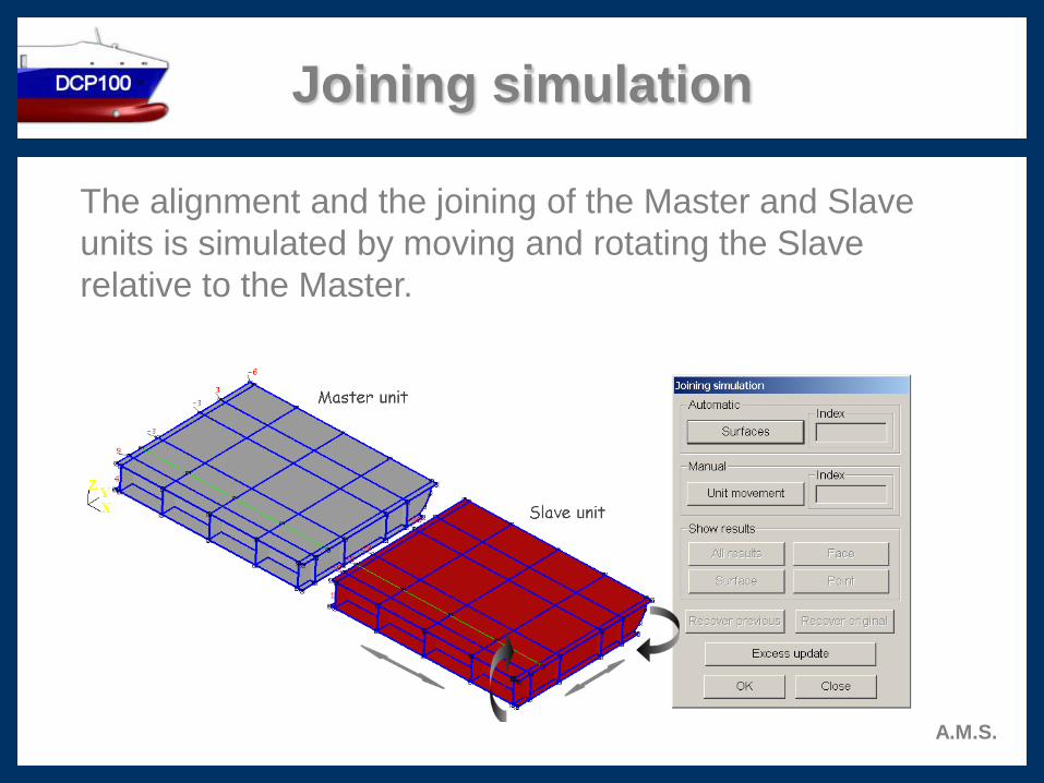
The alignment and the joining of the Master and Slave
units is simulated by moving and rotating the Slave
relative to the Master.
Special displays
A.M.S.
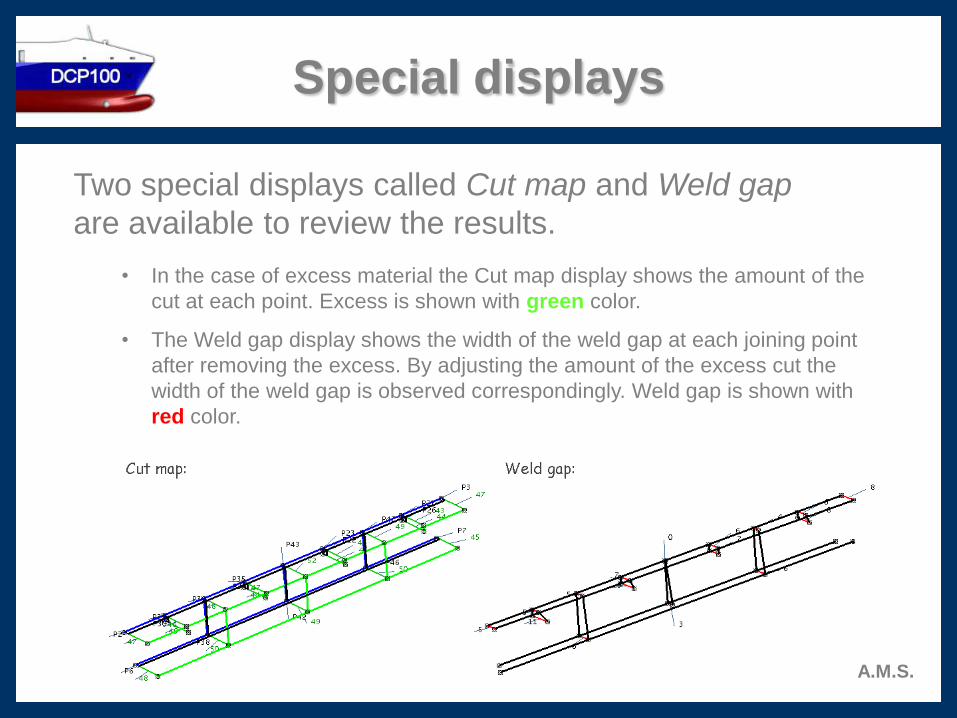
Two special displays called Cut map and Weld gap
are available to review the results.
• In the case of excess material the Cut map display shows the amount of the
cut at each point. Excess is shown with green color.
• The Weld gap display shows the width of the weld gap at each joining point
after removing the excess. By adjusting the amount of the excess cut the
width of the weld gap is observed correspondingly. Weld gap is shown with
red color.
Why DCP100 Simulator ?
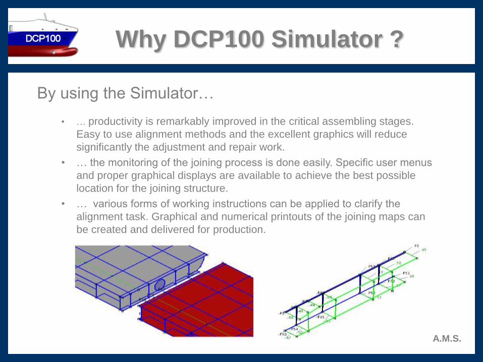
By using the Simulator…
• … productivity is remarkably improved in the critical assembling stages.
Easy to use alignment methods and the excellent graphics will reduce
significantly the adjustment and repair work.
• … the monitoring of the joining process is done easily. Specific user menus
and proper graphical displays are available to achieve the best possible
location for the joining structure.
• … various forms of working instructions can be applied to clarify the
alignment task. Graphical and numerical printouts of the joining maps can
be created and delivered for production.
A.M.S.
More about CAD file import
A.M.S.
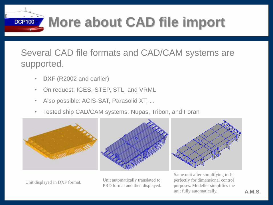
Several CAD file formats and CAD/CAM systems are
supported.
• DXF (R2002 and earlier)
• On request: IGES, STEP, STL, and VRML
• Also possible: ACIS-SAT, Parasolid XT, ...
• Tested ship CAD/CAM systems: Nupas, Tribon, and Foran
Unit displayed in DXF format.Unit automatically translated to
PRD format and then displayed.
Same unit after simplifying to fit
perfectly for dimensional control
purposes. Modeller simplifies the
unit fully automatically.