new generation nip equipment - lu
TRANSCRIPT

New Generation Nip Equipment
Joel Nordin
Division of Machine Design • Department of Design Sciences • LTH • 2010

Division of Machine Design, Department of Design Sciences LTH
Lund University
Box 118
221 00 LUND
ISRN LUTMDN/TMKT 10/5401 SE
Printed by Media-Tryck, Lund, Sweden

i
Preface
The objective of this Master thesis is to replace a hydraulic cylinder with a
servomotor solution. The need for this project has arisen due to the need for increased
precision in future development of the laminator. I was offered this project as a
master thesis project by Peter U Larsson and Lena Skytte at Tetra Pak®. The contact was made through my good friend Emanuel Karlsson who is also an employee at
Tetra Pak®.
This project concludes my studies at Lund University at the Faculty of Engineering and my Master of Science in Mechanical Engineering. The thesis has been performed
within the Packaging Material unit at Tetra Pak®, Lund. There are many people who
contributed to this project, for their help and support I am very grateful.
I would like to thank Tetra Pak® for the opportunity to do my thesis here and for the invaluable experience it has given me. Working this close with the company has
given me insight into working life and how my future hopefully will look like. Many
thanks to Peter U Larsson, Lena Skytte and Per Engvall for entrusting me with this project and for the support/feedback they provided during my work.
I would also like to thank my mentor Håkan Leijon for all the help I have received
during this time, our discussions and his feedback was vital for the making of this project. Many thanks to Emanuel Karlsson as well, for supplying me with the contact
information for this thesis, providing technical/mechanical assistance and for being
my moral support.
I am also very grateful for the help I have received from SKF, Exlar and Lesjöfors. Especially Jörgen Svensson and Per-Erik Andersson at SKF who have been very
helpful and contributed in the solutions and technical support of this project, thank
you.
Lund, May 2010
Joel Nordin

iii
Abstract
In the laminator there are three laminator stations where protective layers are applied
to the paperboard. In each station there are several rollers which help perform the lamination process, the most important rollers to be considered in this thesis are the
nip roller and the chill roller. The nip roller is pushed towards the chill roller using
hydraulic cylinders , thus creating a narrow contact surface between these rollers called "the nip". It is in the nip that the different additives are applied onto the
paperboard (or rather the 'web' which is the printed paperboard when loaded into the
laminator). Some additives are melted onto the paperboard while others are applied in a solid state (foil or film). When the additives are applied onto the web they are
cooled while in contact with the chill roller and then fed to the next laminator section.
Even though the hydraulic cylinders satisfies the specifications for today they will
probably not be able to handle the demands for future operation. With increased need for precision the hydraulics simply cannot reach the same level of precision as a
servomotor operated solution. To help clarify the project mission the problem is
decomposed into three sub problems: linear motion, elasticity and motion guiding. By searching for concept solutions to these problems both externally and internally a
number of concepts are created, the existing motion guiding system is kept. From
these the most potent concepts are chosen using target specifications and a rating system. After further evaluation the final concepts are selected; for the solution to the
linear motion problem the electromechanical cylinder is chosen and the elasticity
problem is best solved with a disc spring package. Performing the necessary analysis
and calculations on these solutions concludes the concept selection phase.
Keywords:
Electromechanical cylinder
Servomotor
Disc spring package
Roller
Line load
Lamination


v
Sammanfattning
Laminatorn är en maskin vars syfte är att belägga kartongmaterial med skyddande
barriärer för att tillgodose hållbarheten för förpackningens innehåll. Laminatorn är
uppbyggd av laminatorstationer där barriärer påföres förpackningsmaterialet i olika steg. I varje station finns ett antal valsar som hjälper till med barriärernas påförande,
de som är intressanta i denna uppsats är nypvalsen och kylvalsen, det är mellan dessa
två som "nypet" skapas. I detta nyp beläggs kartongmaterialet med olika
tillsatsmaterial i både smält och fast tillstånd enligt förpackningsmaterialets specifikation. Dessa tillsatser appliceras under högt tryck som byggs upp genom att
trycka nypvalsen mot kylvalsen med hjälp av hydraulcylindrar.
I änden på varje hydraulcylinder ansluts en ackumulator, dess uppgift är att agera dämpare för systemet genom att ackumulera hydraulvätska i det fall då en överlast
uppträder i systemet och tillåter då kolven i hydraulcylindern att backa. Nypvalsen är
alltså rörlig och nypet kan öppnas och stängas genom att flytta nypvalsen bort från eller mot kylvalsen, nypvalsen har ett ytskikt av mjukare kvalité för att öka
kontaktytans area. Kylvalsen är en motordriven vals vars uppgift är att kyla den heta
smältan som appliceras på kartongmaterialet.
Målet med detta examensarbete är att hitta en servomotorlösning som ersätter befintliga hydraulcylindrar i laminatorn. En ersättare till hydraulcylindrarna är
önskvärd eftersom framtida specifikationer kan bli svåra att uppnå med den
existerande hydrauliken. Med servomotorer är det möjligt att uppnå bättre kontroll och precision i driften.
För att strukturera arbetet används en produktutvecklingsmetodik hämtad från boken
Product Design and Development skriven av Ulrich och Eppinger. I detta projekt
används de tre första stegen produktspecifikation, generering av koncept och val av koncept eftersom tidsbegränsningen på 20 veckor inte tillåter vidare utveckling av
konceptförslaget.
För att förstå vad som krävs av enheten är det viktigt att göra analyser av det existerande systemet. Dessa analyser görs i huvudsak på ackumulatorn eftersom den
utgör ett slutet system och därför kan diverse lagar och regler appliceras vid
uträkningarna. I dessa analyser framkommer att hydraulsystemet riskerar att skada kylvalsen för vissa fel i processen.

vi
Det finns olika faktorer som påverkar nyptrycket och inducerar kraftökningar i
systemet, däribland en överlappande skarv som ger dubbel materialtjocklek i nypet
under en viss tid. Det förekommer också fel i processen som exempelvis då hårda
klumpar stelnad polymer faller ner i nypet. Ett större fel är exempelvis ett banbrott som kan resultera i upprullning av förpackningsmaterial på kylvalsen, såkallat "wrap-
around" som kan ge åtskilliga lagers tjocklek i nypet med påföljande kraftstegring.
Sådan upprullning av förpackningsmaterial kan i värsta fall dessutom innebära att det ozonrör som hänger ovanför nypet dras ned i nypet av en lös ände
förpackningsmaterial. Analyserna visar att mindre avvikelser ger små eller
försumbara kraftökningar medan större fel såsom "wrap-around" kan ge laster större
än vad som är tillåtet för kylvalsen. Det är viktigt att i en framtida lösning ta hänsyn till sådana händelser för att eliminera skador i systemet.
När analyserna är gjorda är det dags att ställa upp en lista över viktiga egenskaper,
som bestämmer hur en kommande lösning ska se ut. Dessa egenskaper rankas efter hur viktiga de är för lösningen, genom diskussioner med tekniska experter och
sakkunniga inom företaget och resultatet av denna rankning ligger till grund för
målspecifikationerna som bestäms. I målspecifikationerna ställs egenskaperna upp i den ordning de blivit rankade, med den viktigaste överst. Sedan förses varje
egenskap med ett idealt värde, det värde en önskvärd lösning ska uppfylla. I de flesta
fall utgörs dessa värden av kraven som är satta på projektet men i de fall det inte går
att sätta ett värde så benämns det som en konstruktionsvariabel och lämnas att tas omhand med hjälp av god konstruktionsförmåga (exempelvis då produkten ska
skyddas mot väta eller ozongas). Målspecifikationerna ligger sedan till grund för det
urval som görs efter att konceptförslagen tagits fram.
För att underlätta framtagningen av konceptförslag delas problemet upp i delproblem,
i detta fall tre stycken: linjär rörelse, elasticitet och styrning av rörelse. För
delproblemet styrning av rörelse bestäms att den existerande lösningen ska behållas i
den mån det är möjligt. Framtagning av konceptförslag för delproblemen sker genom diskussion och sökning internt respektive externt. Intern sökning genomförs på
företaget där olika personer konsulteras och existerande maskineri inspekteras, de
externa sökningarna görs på internet och genom kontakt med olika tillverkare.
När ett antal konceptförslag tagits fram görs ett första urval för att eliminera de
förslag som inte lever upp till specifikationerna, detta urval görs genom rankning av
hur väl konceptet uppfyller en viss egenskap. Efter ett första urval återstår det två konceptförslag för linjär rörelse: en elektromekanisk cylinder (planetrullskruv som
omvandlar ett vridmoment till en tryckande/dragande kraft genom en lösning
liknande den för mutter och skruv) och ett linjärbord (en linjär skenstyrning med
integrerad drift i form av en skruv). För delproblemet elasticitet går tre konceptförslag igenom första urvalet: servomotorstyrning (direkt kompensering i servomotorn för
lastförändringar), tallriksfjäderpaket (tallriksfjädrar staplas mot varandra för att klara
kraft/utböjning förhållandet) och brytpinne (en pinne som konstrueras för att brytas då en viss last överskrids).

vii
Vid djupare undersökning visar det sig att linjärbordet och servomotorstyrning inte är
möjliga lösningar på grund av lastkapacitet och reaktionstid. Dessutom väljs lösningen med brytpinne bort eftersom den inducerar svårkontrollerade variabler i
systemet, såsom materialegenskaper och friktionsproblem. Kvar står den
elektromekaniska cylindern och tallriksfjäderpaketet som alltså är de slutliga
konceptförslagen. Genom kontakt med tillverkare tas specifikationer fram för dessa förslag och de kan nu ställas upp i den slutliga specifikationen. För att göra infästning
möjlig konstrueras en konsol som tillgodoser de belastningskrav som finns på
lösningen. Konsolen samt en axel från tallriksfjäderpaketet analyseras med hjälp av mjukvara som beräknar hållfastheten genom att applicera finita elementmetoden på
de olika delarna.
Elektromekanisk
cylinder
Tallriksfjäderpaket
Konsol
Figur: Konceptlösning


ix
Table of contents
1 Introduction................................................................................................ 1
1.1 Background .................................................................................................... 1
1.2 The company ................................................................................................. 1
1.3 The nip unit .................................................................................................... 2
1.4 Objectives ...................................................................................................... 2
1.5 Limitations ...................................................................................................... 2
2 Development methodology ....................................................................... 3
2.1 Product specifications ..................................................................................... 3
2.1.1 Target Specifications ............................................................................ 3
2.1.2 Final specifications................................................................................ 3
2.2 Concept generation ........................................................................................ 3
2.2.1 Clarify the problem ................................................................................ 3
2.2.2 Search externally .................................................................................. 4
2.2.3 Search internally ................................................................................... 4
2.2.4 Explore systematically........................................................................... 4
2.3 Concept selection ........................................................................................... 4
2.3.1 Concept scoring .................................................................................... 4
2.3.2 Concept presentation ............................................................................ 4
2.3.3 Final concepts selection ........................................................................ 4
3 Detailed description .................................................................................. 5
3.1 The nip unit .................................................................................................... 5
3.1.1 The nip roller ......................................................................................... 6
3.1.2 The chill roller ....................................................................................... 6
3.2 Nip pressure ................................................................................................... 6
3.3 Nip roller movement ....................................................................................... 6
x
4 Problem formulation .................................................................................. 7
4.1 Advantages and disadvantages - Hydraulics ................................................... 7
4.2 Advantages and disadvantages - Servo .......................................................... 8
4.3 Paper splice, wrap-around and other errors .................................................... 9
5 Analysis of hydraulic system ................................................................. 11
5.1 General data ................................................................................................ 11
5.2 Accumulator ................................................................................................. 12
5.3 Wrap-around and overlap splice ................................................................... 17
5.4 Conclusions and reflections .......................................................................... 21
6 Product development .............................................................................. 23
6.1 Methodology................................................................................................. 23
6.2 Product specifications ................................................................................... 23
6.3 Concept generation ...................................................................................... 26
6.3.1 Linear motion ...................................................................................... 26
6.3.2 Elasticity ............................................................................................. 28
6.3.3 Motion guiding .................................................................................... 29
6.4 Concept selection ......................................................................................... 30
6.4.1 Linear motion ...................................................................................... 30
6.4.2 Elasticity ............................................................................................. 33
6.4.3 Motion Guiding.................................................................................... 36
6.5 Final concept selection ................................................................................. 36
6.5.1 Linear motion ...................................................................................... 36
6.5.2 Elasticity ............................................................................................. 38
6.5.3 Console .............................................................................................. 42
6.5.4 Final specification ............................................................................... 43
6.6 Mock-up design ............................................................................................ 44
6.7 Structural analysis ........................................................................................ 45
6.7.1 Console .............................................................................................. 45
6.7.2 Disc spring shaft ................................................................................. 48
6.8 Conclusions and reflections .......................................................................... 50
7 Results and conclusions......................................................................... 53
7.1 Suggestions and recommendations .............................................................. 54

xi
Appendix A: References ............................................................................... 55
Appendix B: Linear actuators - Comparison Data ...................................... 57
Appendix C: SKF Linear unit ........................................................................ 59
Appendix D: Kistler load cell ........................................................................ 61
Appendix E: Lesjöfors disc spring package ............................................... 65


1
1 Introduction
Tetra Pak® Packaging Solution has a thesis on how to further develop the nip
mechanism in the laminator station. The basic idea is to replace a hydraulic solution with an servomotor equivalence. The main reason for this change is to get better
precision in the nip to be able to cope with future specifications.
1.1 Background As one of the world’s largest carton package manufacturer, Tetra Pak® handle all
processes from the raw paperboard to the filled package found in the retailer’s store.
In the company's factories paperboard is processed into packaging material which is used in filling machines at the local food and/or beverage producers. The laminator is
the machine that applies the protective layers onto the large rolls of printed and
creased paperboard.
1.2 The company Ruben Rausing founded Tetra Pak® in 1951. His idea was to produce carton
packaging for food and beverages. This approach was very successful and today the
company has expanded all over the world and is a well known brand for most people. Tetra Pak® has since then expanded their field of knowledge to include a wide
variety of packaging products for consumables like cheese, fruit and wine. Apart from
packaging, Tetra Pak® is also involved in treating and distributing the food in a healthy manner. Tetra Pak® is a member of the Tetra Laval® group, this group has
two other members: De Laval and Sidel. De Laval, with their base in Sweden,
produces equipment for milk production and is well known for their automatic
milking system VMS. The French company Sidel develops and manufactures plastic bottles machinery. This thesis is performed at the department of Packaging Material
in Lund, Sweden. Lund is the home of Tetra Pak® and the place where most research
and development is done. Besides the development and engineering unit (D&E) there are also large facilities for packaging manufacturing and assembly of packaging
machinery, in fact these divisions are the largest facilities throughout the whole
company.
1 Introduction
2
1.3 The nip unit The laminator consists of several sections with different functions, this thesis focuses on the laminator station and especially the nip which is the contact surface between
the nip roller and the chill roller. The nip roller is pushed against the chill roller with
hydraulic cylinders and the lamination additives are applied in the nip that is created between these rollers. When all layers have been applied to the printed and creased
paperboard it is once again stored on a roll. In the next step this roll is sent to the
finishing section where it is slit into narrower rolls and possible defects are removed.
After being loaded onto a pallet it is ready to be delivered to the filling machine at the food or beverage producer.
1.4 Objectives The objective of this thesis is to replace the hydraulic cylinders in the nip unit with an electric solution. There are a number of disadvantages with a hydraulic system, low
precision and leakage of hydraulic fluid being two of them. Though the hydraulic
system works satisfactory in the present situation, future specifications will be difficult to reach with this system. Precision in the nip is the most important factor
that has lead to the formulation of this thesis. Aside from keeping a constant load
between the rollers, the system must also be able to handle splices as well as
occurrence of solid laminate fragments, wrap-around that can occur in case of web break and other deviations from normal operation. With the hydraulic cylinders these
deviations are easily handled with the assist of pressurized accumulators. To take care
of these variations in a rigid servo application it is crucial to have some cushioning or release system. Thus, the objective must be expanded to include a mechanism to
absorb variations in the lamination process that otherwise would damage expensive
equipment.
1.5 Limitations The thesis spans over a period of twenty weeks, since this include writing the report
and prepare the presentation the development process is shorter than that. With
regards to this time limit the main focus will be on dimensioning and modelling the unit while taking surrounding issues into consideration. The ambition is to have a
complete unit specified by the end of the thesis, if this is not possible there will be
trade-offs regarding drawings, automation, software and other parts that are not essential in the completion of this thesis.

3
2 Development methodology
The steps in a structured development project are well described by Ulrich and
Eppinger1 and these steps form the layout of this thesis. With their methodology the
product development process is broken down into parts and becomes more
understandable and easier to work with.
2.1 Product specifications Basically the specification contains metrics (properties) that are derived from user
demands. These metrics and corresponding values represents the performance of the
unit and describes what the product has to do but not how to do it.
2.1.1 Target Specifications
In the ideal case, these values are the criteria for creating the concept solution. The
target specifications must now be reworked so that every value is realistic, this is
done through trade-off’s where it is possible but also by consulting specialists and other resources.
2.1.2 Final specifications
All demands for the solution are now set and the concept generation can begin with a starting point in the specifications. The concepts that can’t fulfill the specifications
must either be improved, combined with others or, as the last option, be disregarded.
2.2 Concept generation With help from the specifications it is now time to start looking at solutions for the
problem. This step is the most important event in the product development process
and also the most time consuming part. To address this rather wide area it is
recommended to divide it into smaller constituents as follows.
2.2.1 Clarify the problem
To be able to handle a complex problem it is sometimes necessary to break down the
entire problem into smaller parts, a sort of decomposition. By solving these smaller sub problems, the final result is often better and solutions that would otherwise be
disregarded, or not even discussed, are lifted and taken into account.
1 Product Design and Development - Karl T Ulrich, Steven D Eppinger - Third edition

2 Development methodology
4
2.2.2 Search externally
In order to find already existing products and solutions an external search is necessary. This search provides input from lead users and technical information from
suppliers. Studies of technical journals and consulting experts in relevant areas are
also important steps to help further concept generation.
2.2.3 Search internally
A search within the company or project group to make sure that all ideas are
considered, this step is often more open than the other because the knowledge is
already present inside the group. A common platform for making an internal search is a brainstorming session where all ideas are pronounced in a non-analyzing
environment where both impossible and realistic solutions are considered.
2.2.4 Explore systematically
After searching for solutions to the problem or any of the sub problems it is important
to organize and synthesize these fragments so that complete solutions may be found.
By creating a concept classification tree it becomes easier to see which solutions that can be combined and those that cannot.
2.3 Concept selection Finding the most potential solutions is sometimes a difficult process but with the tools
provided it can be done easier and with a better end result. Concept scoring is helpful when making the selections and will be used in this thesis. There is another similar
method called concept screening which will not be used.
2.3.1 Concept scoring
By rating the concepts in relation to a reference solution (in most cases a competing
product or a present solution) the selection process becomes less complex. The
scoring also facilitates comparisons of combinations of different concepts but also
improvements in general, to be able to present the best solution possible.
2.3.2 Concept presentation
Though the concept presentation is not standard procedure according to Ulrich &
Eppinger, this thesis requires the involvement of the persons in charge of the development. So when the best concepts have been selected, these are presented to
the board members. They are required to rate the concepts in a similar way that was
done in the previous section.
2.3.3 Final concepts selection
With the input from the board members, it is time to select one or two concepts that
will be further developed. With these final concepts in hand the time has come for the
final design to begin.

5
3 Detailed description
The laminator is a machine that produces packaging material by adding different
protective layers onto the printed paperboard or web as it is called when being processed. In every laminator there are laminator stations and it is in these stations
that the various additives are applied. To ensure good packaging performance these
layers are applied in a high pressure contact surface between two rollers, this is called the nip.
3.1 The nip unit The nip is created between the nip roller and the chill roller where the melted polymer is distributed, the pressure is achieved by pushing the nip roller against the chill roller
with the help of hydraulic cylinders, see figure 3-1. After being applied to the web the
polymer is cooled while in contact with the chill roller and then delivered to the next
laminator station or the rewinder unit.
Nip roller
The nip
Chill roller
Figure 3-1: The nip unit

3 Detailed Description
6
3.1.1 The nip roller
To ensure the quality of the package material it is necessary to control the way in
which the protective layers are applied to the paperboard. The nip roller is a steel
roller with a soft coating to increase contact surface area. It rests in bearing housings at both ends which are connected to hydraulic cylinders with attached, gas filled,
accumulators
3.1.2 The chill roller
The chill roller has the main functions of cooling any hot additives applied, it is also driven and helps drive the paperboard or ‘web’ through the machine. This roller has a
very fine surface along with internal cooling channels to exert the best cooling
performance possible. The cooling channels weakens the structural integrity of the chill roller and since it is also a very expensive roller it will be a dimensioning factor
when calculating load between rollers.
3.2 Nip pressure To ensure that the additives are firmly in place the procedure of applying these layers
is done under constant high pressure. To be able to reach the specified line load (load
between the nip roller and the chill roller) the hydraulic cylinders must exert a force
in both ends of the nip roller that corresponds to several tons of weight. This load magnitude requires high stability and rigid mounting which can be seen in the
mechanical design of the whole nip unit.
3.3 Nip roller movement The nip roller is mounted on profile rail guides and is operated by the hydraulic
cylinders for closing and opening the nip. This motion is done mainly at start up and
shutdown of the process but also for maintenance and if a process error occurs. In
case of routine maintenance or process error the nip will be opened manually by the operator.

7
4 Problem formulation
To better understand the need of this project the advantages and disadvantages are
listed for the hydraulic solution and the servomotor solution respectively.
4.1 Advantages and disadvantages - Hydraulics The hydraulic cylinder has many advantages that must be compensated for when
replaced. There are also disadvantages which describe the need for change. The most important factors:
Compact:
Since the hydraulic cylinder is placed away from the hydraulic unit, the space
required for this solution is minimal. However, this also means that the hydraulic unit must be placed elsewhere leading to additional space requirements in the
facility.
Accumulator
This gas damper makes load regulation easy at a low space impact. The
disadvantage of the accumulator is the restrictions in the hydraulic system between the cylinder and the accumulator which renders the system rather stiff
for fast load changes in comparison with a spring system.
Pressure regulation
Nominal pressure is set directly on the hydraulic unit and kept for as long as the lamination process is active.
Hydraulic fluid
Even though modern systems have less chance of leakage and the risk of
hydraulic fluid ending up on the packaging material is negligible it can cause problems in other areas (slippery floors, fluid covered components etc.).
Precision
To meet future demands the hydraulic cylinders will have problem reaching the
precision needed. A servomotor solution can fine tune the process in a more
detailed way than the hydraulics.
Tubes and hosing
The space required for hydraulic pipes and hoses are generally larger than for the
electric setup, the possibility of leakage must also be considered.

4 Problem formulation
8
4.2 Advantages and disadvantages - Servo The major advantages and disadvantages of the servomotor solution are as follows.
Precision
The precision in a servo motor is superior to most alternatives and is one of the
main reasons for choosing this solution. By choosing different gear ratio for the
servo motor it is possible to further improve precision up to the point where the other components are not sufficiently precise. Changing gear ratio has, of course,
a large impact on speeds and forces and therefore creates a number of
possibilities to adapt the solution for the actual demands.
Control system
The ability to control the motion with software programming is a big advantage and makes the process controllable in every detail. Since the system also gives
feedback from the operation it can be used to detect certain errors and
compensate for them. By utilizing these additional features it is possible to gather more exact data and to be able to further analyze the process.
Stand-alone product
With the exception of some wiring and the controller unit the solution is mounted
as one unit with no external components, which makes exchange and maintenance swift and easy.
Clean system
By using an electrical unit the system will not be dependent on hydraulics and/or
pneumatics and it also removes the sources of leakage.
No internal elasticity
Since the system is rigid in its construction the system will not be able to handle vibrations and deviations in thickness of the material. The servomotor will not
compensate feedback forces by moving in either direction because of its internal
design. This, however, is a necessary disadvantage since it permits exact adjustment and good precision.
Large, heavy unit
Since all parts of this solution will be assembled into one unit, it will be
significantly larger and heavier than the hydraulic cylinder.

4 Problem formulation
9
4.3 Paper splice, wrap-around and other errors Overlap splice and solid polymer pieces are two examples of variations that induce small load changes in the nip. An example of a larger deviation is a web break that
can cause wrap-around on the chill roller. This means that the chill roller will wind up
several layers of material and the pressure between nip- and chill roller will increase dramatically before the emergency system is able to stop the operation.
The worst case scenario is when the free end of the web after a web break will drag
an aluminium pipe, hanging above the nip, down into the nip.

11
5 Analysis of hydraulic system
These analysis are the foundation of the design work, the results determines how the
solution must function. Since the geometry is symmetrical, calculations are done for one side of the laminator station only. In the first section the data used in the
calculations is presented along with the sources of information. The different factors
and properties are denominated to be more easily handled. In the second section the accumulator and its function are described along with some calculations of
limitations. In section three there are analysis of how wrap-around and overlap splice
affects the pressure between nip- and chill roller. The final section briefly presents the case when the ozone pipe enters the nip.
5.1 General data Calculations made in the following sections are based on data from the hydraulic
cylinder and the gas accumulator. Since this solution is handling the deviations in an acceptable way it is logical to use these properties as a reference when designing the
new unit. The following data has been collected for the paperboard, accumulator,
hydraulic cylinder and the laminator, see table 5-1. All values are upper extreme values and are safe to use as dimensioning factors and are gathered from either
manufacturers’ datasheet2 or from project specification. The stroke equivalent for the
hydraulic cylinder is based on the specifications for the new solution and is there to be able to perform a comparison between the existing hydraulic cylinder and the new
servomotor solution.
2 www.pmchytech.com 2010-01-18

5 Analysis of hydraulic system
12
Va = Volume (m3) 1 0,00075
Lp = Preloaded accumulator (N/mm) 2 30
Hydraulic Cylinder - ISO 80/56-160MT1
Øp = Piston diameter (m) 1 0,08
Ør = Rod diameter (m) 1 0,056
Ac = Cylinder - cross section area (m2) 1 0,00503
sc = Cylinder, stroke (m) 1 0,16
sce = Cylinder, stroke equivalent (m) 0,06
Laminator
Lop = Operational line load (N/mm) 3 50
Øc = Chill roller diameter (m) 3 0,9
Ls = Maximum permitted line load (N/mm) 3 70
vw = Web speed (m/min) 3 800
ts = Stop time, web break (s) 2 10
hp = Paperboard thickness (m) 2 0,00055
wm = Width (m) 3 1,65
Data
Accumulator - SBO210-0.75E1/112U-210AK
Data provided by:
1 PMC Hytech www.pmchytech.com [2010-03-17]
2 Tetra Pak® documentation
3 Skytte, Lena, 2009, New generation nip equipment specification_Issue 3
5.2 Accumulator In the hydraulic system there is an accumulator acting as a spring to add elasticity to
an otherwise stiff system. The accumulator is placed in the back end of the hydraulic
cylinder and will accumulate hydraulic fluid that is displaced when pressure increases in the nip. The nitrogen and the hydraulic fluid are separated by a diaphragm which
also keeps the gas from escaping through the bottom connector while disconnected
and when system pressure is below the preload pressure.
Table 5-1: General data

5 Analysis of hydraulic system
13
In figure 5-2 the first state corresponds to a line load below the equivalent preload
pressure or a completely unloaded system, in the second state the load is just above preload pressure and hydraulic fluid has filled up some regions of the accumulator.
Finally, in the third state, the pressure increased significantly and hydraulic fluid now
constitutes the major volume in the accumulator.
Using data provided in table 5-1 some calculations can be made to determine the
limitations of the accumulator, see table 5-3.
Accumulator - SBO210-0.75E1/112U-210AK
Fp = Preload (N) 24750
Pp = Preload pressure (MPa) 4,92
Fop = Operational load (N) 41250
Pop = Operational pressure (MPa) 8,20
Calculations I
The preload is the load that correspond to the specified line load equivalent .
Figure 5-2: Accumulator
Table 5-3: Calculations I

5 Analysis of hydraulic system
14
To better understand what happens in terms of forces and pressures when chill roller wrap-around or overlap splice occurs the amount of material accumulated is described
as an increase in thickness between nip roller and chill roller. This change in
thickness can then be seen as a pressure increase in the hydraulic cylinder or a force increase in the piston rod.
By using Boyle’s law3 (polytrophic changes of state) that applies for systems where
there are slow expansions/compressions and small or no energy loss it is possible to
calculate every step of the process. This law states that the volume-pressure relation
will be constant, thus . Since the hydraulic fluid can be considered
incompressible the change in volume will occur in the accumulator which is filled
with nitrogen but the pressure change is distributed throughout the system.
a. System at 30N/mm ► System at 50N/mm
P1a 4,920477137
V1a 0,00075
P2a 8,200795229
V2a 0,00045
b. System at 50N/mm ► Maximum stroke
P1b 8,200795229
V1b 0,00045
P2b 24,90120009
V2b 0,0001482
c. System at 50N/mm ► Maximum safe stroke
P1c 8,200795229
V1c 0,00045
P2c 11,48111332
V2c 0,000321429
ΔVc 0,000128571
Pressure - Volume I
3 New World Encyclopedia www.newworldencyclopedia.org [2010-04-13]
Table 5-4: Pressure-Volume I

5 Analysis of hydraulic system
15
a.
In the first load case the system will go from preloaded accumulator state to normal operation load state, see table 5-4. In the preloaded state the volume equals the
specified volume of the accumulator and the pressure as described in
table 5-3 at preload . In normal operation state the pressure is raised to the
equivalent to a line load of 50N/mm whilst the compressed accumulator
volume will be calculated through:
The compressed volume:
is the normal operating volume for the accumulator since it is the gas volume at
50 N/mm, it is denominated and is found in table 5-5 below.
b.
In case the full stroke of the cylinder is accumulated starting from normal operating
mode while the gas volume will be compressed from normal operating
volume to the remaining gas volume at full cylinder stroke
, see table 5-4. is calculated by taking the normal operating volume
and subtracting the cylinder cross section area times the cylinder equivalent max
stroke :
Now it is possible to calculate , the pressure at max stroke which will be referred
to as in table 5-5:
Converted into a cylinder load:

5 Analysis of hydraulic system
16
c.
In case the stroke length for the specified maximum force allowed is derived from the highest line load that the chill roller can withstand. Given the largest permitted line
load the corresponding safe load becomes:
consequently the pressure:
As the initial state is normal operation, the gas volume and the pressure are
unchanged and the final pressure equals the
maximum safe pressure (see table 5-4), thus the resulting volume becomes:
This is the gas volume at the permitted load, to be able to calculate the corresponding
cylinder stroke the difference in volume is required, this is given by taking the
accumulator operating volume and subtracting the actual gas volume :
By dividing with the cylinder cross section area the safe stroke is obtained:

5 Analysis of hydraulic system
17
The results are summarized in the following table.
Results I
Accumulator - SBO210-0.75E1/112U-210AK
Vop = Operational volume (m3) 0,00045
Vmax = Acc. Volume, maximum stroke (m3) 0,0001482
Pmax = Pressure, maximum stroke (MPa) 24,90
Fmax = Load, maximum stroke (N) 125253
Fs = Maximum safe load (N) 57750
Ps = Maximum safe pressure (Mpa) 11,48
ss = Maximum safe stroke (m) 0,0256
5.3 Wrap-around and overlap splice
When a wrap-around occur the material accumulated on the chill roller causes an increased pressure between chill- and nip roller. This increase in pressure results in
hydraulic fluid being pushed back in the cylinder by the cylinder rod. This excessive
fluid flows into the accumulator reducing the gas volume, thus building up pressure in the gas. By calculating the increase in pressure it is possible to see which loads to
expect in the system when wrap-around or overlap splice occurs. First the basic data
for the process and material must be calculated as seen in table 5-6.
Calculations II
Laminator
ab = Acceleration (m/s2) -1,33
vb = Average speed, deceleration (m/s) 6,67
rb = Revolutions before standstill (no.) 23,6
hw = Wrap-around thickness (m) 0,026
ΔVs = Volume, overlap splice (m3) 2,77E-06
ΔVw = Volume, wrap-around (m3) 1,30E-04
Table 5-5: Results I
Table 5-6: Calculations II

5 Analysis of hydraulic system
18
Assuming linear deceleration the process has the following properties:
With this basic information it is possible to once again use Boyle’s law (as seen in
previous section) to compute the changes in pressure and volume in the accumulator.
d. System at 50N/mm ► System, overlap splice
P1d 8,200795229
V1d 0,00045
P2d 8,251523763
V2d 0,000447234
e. System at 50N/mm ► System, wrap-around
P1e 8,200795229
V1e 0,00045
P2e 11,54896619
V2e 0,00031954
Pressure - Volume II
Table 5-7: Pressure -Volume II

5 Analysis of hydraulic system
19
d.
The system will be subjected to an overlap splice, which actually means that a length of double paperboard thickness will pass through the rollers. In this case the initial
state is when the system is in an operational state (see
table 5-7) and the change in volume for an overlap splice as calculated
previously, this gives the volume, pressure and pressure change through:
The corresponding force in the cylinder:
e.
The second load case determines the pressure and volume change after a 10 s
wraparound with breaks applied. The initial state is normal operation
(see table 5-7) while the final volume is calculated by using the
change in volume for wrap-around to calculate the new volume V2c and
pressure P2c as:
The corresponding force in the cylinder:

5 Analysis of hydraulic system
20
The results are summarized in the following table.
Results II
Overlapping splice
Vos = Volume, overlap splice (m3) 0,0004
Pos = Pressure, overlap splice (MPa) 8,25
Fos = Load, overlap splice (N) 41505
Wrap-around (10s)
Vwa = Volume, wrap-around (m3) 0,0003
Pwa = Pressure, wrap-around (MPa) 11,55
Fos = Load, wrap-around (N) 58091
Depending on what time the new system requires to react on a wrap-around the
amount of material accumulated on the chill roller varies, therefore it is interesting to look at how this amount varies over time. Material thickness versus time respective
force versus time is plotted in the following graph by calculating the following
equations.
The deceleration is based on the ten seconds specified stop time as calculated
before:
Table 5-8: Results II

5 Analysis of hydraulic system
21
Using Boyles law again, the pressure is derived:
Plotting the wrap-around thickness and force over time:
0
5
10
15
0
5
10
15
20
25
0,5 1,5 2,5 3,5 4,5 5,5 6,5 7,5 8,5 9,5
Lo
ad c
han
ge
(kN
).
Th
ick
nes
s (m
m).
Time (s)
Wrap-around factors
Thickness
Load change
5.4 Conclusions and reflections From the point where the contact between nip- and chill roller is initialized the system
line load increases up to 50 N/mm which is normal operation. The accumulator is preloaded to 30 N/mm which means that below this load it is unaffected and its
volume constant.
Figure 5-9: Wrap-around factors

5 Analysis of hydraulic system
22
Going from 30 N/mm to 50 N/mm the gas volume inside the accumulator will
decrease from 0,75 l to 0,45 l leading to a pressure increase from 4,92 MPa to 8,20 MPa or the equivalent load increase from 24,75 kN to 41,25 kN. These are the figures
for normal operation and only a control and a verification of the given data for
operation.
The equivalent max stroke in the cylinder (60 mm) will result in a pressure of
24,90 MPa and a gas volume decrease in the accumulator down to 0,15 l. The force at
this pressure will be 125,3 kN thus well beyond the 57,75 kN specified for the chill
roller and therefore leading to severe damage to the chill roller. It is clear that the accumulator will never be completely filled (which means the full stroke of the
cylinder can be utilized in an overload situation) but also that a full stroke probably
leads to irreparable damage in the system.
To determine what stroke the accumulator can handle without having the pressure
exceed the maximum force specified for the chill roller (57,75 kN) the force is
converted into the corresponding pressure (11,48 MPa) and then reinserted into the Boyle’s equation. The pressure increase from 8,20 MPa to 11,48 MPa gives the
volume decrease from 0,45 l to 0,32 l and the corresponding stroke 25,6 mm. Note
that this stroke cannot be used instantly since the hydraulic fluid has a relatively high
viscosity which in combination with restrictions on the way to the accumulator results in stiffer behaviour for very quick pressure changes while it acts as a damper when
changes are slower.
The overlapping splice will result in very small pressure changes in the system, going from 8,20 MPa to 8,25 MPa does not induce any noticeable forces in the system.
Looking at a web speed of 800 m/min or 13,3 m/s it is understandable that a splice
will pass through the nip almost instantaneously, this means that the pressure increase
caused by this change in thickness will look very much like an impact to the system.
When looking at wrap-around it is clear that a ten second wrap-around will cause a
significant pressure increase in the system, after this time period the material
thickness can be as thick as 25,9 mm. This scenario is based on the assumption that a long piece of web will be free at the point of the web break, causing it to be drawn
into the nip together with the wrap-around. This means that the amount of material
accumulated every turn will be twice the material thickness. A full ten second wrap-around results in a load change from 41,25 kN to 58,09 kN which is slightly above
the permitted force of the chill roller. In the hydraulic system there is a potential
chance of causing damage to the chill roller if a wrap-around of this type occurs.
23
6 Product development
The presentation of the product development procedure is presented here along with
some discussions and reflections.
6.1 Methodology Following Ulrich & Eppinger's methodology this thesis is divided into the
corresponding sub-categories and decompositions. By following their methodology the work becomes more structured both in writing and execution. Though the
methodology outline is clear it is necessary to adapt the different steps to the actual
process, therefore some deviations from the theoretic plan may occur.
6.2 Product specifications Most equipment and process data were presented at the start-up meeting for the
thesis, these values specify the demands on the solution and ensures the products
performance in future usage. The data4 is converted into a list of metrics and
additional items are added to get a complete functions description, see table 6-1.
With the list of metrics it is easier to see the result of every specification and every
metric can now be ranked by setting their impact values respectively. All metrics are ranked using a numeric scale starting from one which is the most important metric.
The ranking process is performed in collaboration with co-workers where their
opinions are compiled into the final ranking through discussions.
4 Skytte, Lena, 2009, New generation nip equipment specification_Issue 3

6 Product development
24
No. Metric Impact Unit
1 Line load 2 N/mm
2 Linear motion 6 mm
3 Linear motion speed 7 mm/s
4 Detect and act, load change 5 s
5 Detect and act, paper splice 4 s
6 Adaptive mounting properties 9 Subjective
7 Width (across web direction) 15 mm
8 Length (web direction) 12 mm
9 Height (vertical) 17 mm
10 Interface compatibility 8 Protocol
11 Ozone resistant 11 Subjective
12 Heat resistant 16 ⁰C
13 Water resistant 18 Subjective
14 Melted PE resistant 19 Subjective
15 Maintenance friendly 10 Subjective
16 Price 13 SEK
17 Safety compliance 1 Protocol
18 Precision 3 mm
19 Weight 14 kg
List of Metrics
A brief description of the most important metrics:
1. Line load (N/mm) - is specified directly in process data and is, together with the
precision, the key parameter for the product to meet the demands. The line load is the force created in the contact between nip- and chill roller, in reality it is a pressure
distributed on a narrow area.
2. Linear motion (mm) - the possibility to open the nip for start-up/shutdown and
maintenance.
3. Linear speed (mm/s) - capacity to move the nip roller the specified length at a
certain speed.
4. (and 5.) Detect and act, load change/paper splice - elasticity of the system measured in the ability to compensate for a small load changes (paper splice) and a
larger load changes (wrap-around, ozone pipe conk out etc).
17. Safety compliance - it is vital that the product meet the company safety standards.
Table 6-1: List of metrics

6 Product development
25
18. Precision (mm) - the ability to control the nip pressure in fine detail to reach
future demands.
The subjective unit means that the metric can be achieved through good design, for
example the solution can be water resistant if the design is well protected and not
exposed to the environment.
No.Metric
No.Metric Unit Value
1 17 Safety compliance Protocol SIL-2, PFL-D
2 1 Line load N/mm 50±2
3 18 Precision mm < ± 0,5
4 5 Detect and act, paper splice s 0
5 4 Detect and act, load change s 0
6 2 Linear motion mm 60-100
7 3 Linear motion speed mm/s 12-20
8 10 Interface compatibility Protocol Profibus/Profinet
9 6 Adaptive mounting properties Subjective Design Parameter
10 15 Maintenance friendly Subjective Design Parameter
11 11 Ozone resistant Subjective Design Parameter
12 8 Length (web direction) mm <800
13 16 Price SEK ≤ Hydraulics
14 19 Weight kg <100
15 7 Width (across web direction) mm <280
16 12 Heat resistant
⁰
C Design Parameter
17 9 Height (vertical) mm <400
18 13 Water resistant Subjective Design Parameter
19 14 Melted PE resistant Subjective Design Parameter
Target Specifications
The target specifications, see table 6-2, are the properties from the list of metrics
sorted by importance from ranking and inserted into a new list with the most important metric on top. To each metric a value is assigned and that is the ideal value,
meaning what is wanted in the best possible solution. These values are in some cases
data direct from project specification but can also be information from current system and otherwise desired properties. The values for line load, precision, linear motion
and linear motion speed are gathered directly from project specification while the
safety compliance and interface compatibility are standards for the company.
Measurements are taken from the existing hydraulic solution, if the new solution can fit in the laminator station without making extensive change to the general design
this can significantly lower costs and ease assembly in existing machinery.
Table 6-2: Target specifications

6 Product development
26
The design parameters represent the possibility to design the solution in a way that it
will resist the environments variables or so that it will be easy to mount on existing equipment.
6.3 Concept generation The target product specifications will be the foundation for the concept generation. The suggestions presented in this chapter are the result of brainstorming sessions,
searching the internet, looking at similar solutions and looking at product datasheets.
To get the best result it is important to regard every suggestion and to keep a large
portfolio of ideas to consider when making the concept selection.
To handle the complexity of the problem it is decomposed into three parts; guiding,
elasticity and motion guiding. By doing this it is possible to focus on one part at a
time and then combine these suggestions in the end. Making the concepts as attractive as possible in an investment point of view is important and therefore the work aims at
replacing as few parts as possible along with making assembly and mounting as easy
as possible.
6.3.1 Linear motion
The goal is to find the best way of moving the nip roller in a well controlled motion.
The device has to be electrically manoeuvred, produce a linear motion and be able to
comply with the listed specifications. The possible solutions presented here have been produced through discussions with colleagues and searches made on the internet.
Gear rack, stationary rail
The nip unit is mounted together with a servomotor and will move along the gear rack
that is mounted on the frame. Movement is
done through a gear mounted on the engine that drives the nip roller unit along the
stationary gear rack.
Gear rack, rail motion
The nip unit is mounted on the gear rack
which is manoeuvred by a servomotor with a mounted gear. This is the inverted version of
the previous solution but the gear rack is now
mobile while the servomotor is stationary.
Figure 6-3: Gear rack, stationary rail
Figure 6-4: Gear rack, rail motion
6 Product development
27
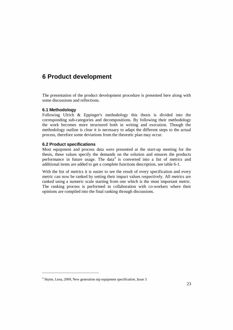
Electromechanical cylinder
With the servomotor connected on the back
the linear motion is created by a planetary roller screw. Since the unit is compact and
robust it can withstand large forces and fast
movement without losing precision.
Positioning table
A system with an internal screw mechanism
and a rail guide that handles both motion and
guiding of the nip roller. It resembles the present profile rail guide solution but with an
integrated drive mechanism.
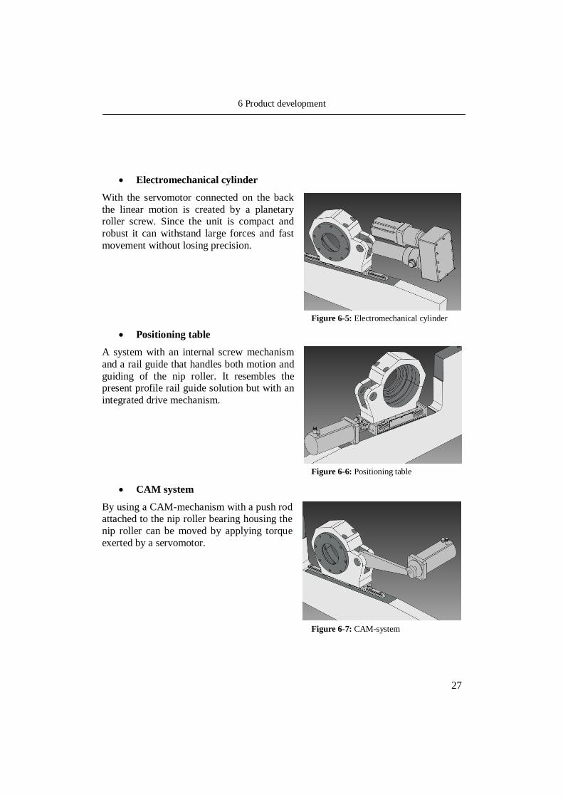
CAM system
By using a CAM-mechanism with a push rod attached to the nip roller bearing housing the
nip roller can be moved by applying torque
exerted by a servomotor.
Figure 6-5: Electromechanical cylinder
Figure 6-6: Positioning table
Figure 6-7: CAM-system

6 Product development
28
6.3.2 Elasticity
The solution must be able to handle sudden load changes and deviations from normal operation, there must be some kind of elasticity in the system. There are a few good
ways of creating this elasticity in a system with these large forces. The possible
solutions are:
Electromagnetic release mechanism
By attaching the drive system to an
electromagnetic coupling the connection can
be released when the load exceeds a certain value. The released system will be restored to
its initial position by springs inside the
coupling. This solution will only handle push and pull forces and must be positioned
between nip roller bearing housing and the
linear solution.
Overload torque coupling
By installing an overload torque coupling
between the servomotor and the linear unit
the driving shafts will be allowed to rotate independently to each other when an
overload occurs. It depends on the linear
unit's ability to translate the linear force to a rotational torque in both directions. This
coupling is very similar to the coupling found
in most cordless drills on the market.
Servomotor control
Sensing pressure changes in the nip by load
cell or similar equipment and then compensate directly by controlling the
servomotor rotation means that no additional
equipment is required.
Figure 6-8: Electromagnetic release mechanism
Figure 6-9: Overload torque coupling
Figure 6-10: Servomotor control

6 Product development
29
Disc spring
Disc springs have capacity to endure large
loads but small deflections only, in a disc spring package it is possible to combine
several disc springs to get the desired
properties.
Breakpin
This solution offers an overload failsafe
mechanism and is basically a pin designed to be the weakest part in the unit and to break at
a certain load. When the pin breaks it must be
replaced with a new one manually.
6.3.3 Motion guiding
The nip roller must be guided in a low friction solution that keeps the housing parallel to the
machine frame. Since there is already a
working solution to this problem that works well there is no point in replacing it unless the
design is altered in a radical way.
Figure 6-11: Disc spring
Figure 6-12: Break pin
Figure 6-13: Motion guiding

6 Product development
30
6.4 Concept selection Choosing the right concept solutions is important and therefore it is vital not to exclude concepts that seem bad at a first glance. By setting up a selection table it is
possible to compare the concepts with each other and with an already existing
solution. The criteria in the selection matrix are gathered from the target specification table and modified slightly to hold the most important properties. The criteria
concerning profitability and usability are added to provide a more complete analysis.
Since pricing and precise design of the concepts are not known in this stage the values
are estimated from an engineering point of view and, when possible, gathered from the manufacturers. The concepts are rated in the categories "specification
compliance" and "other" where the first section holds the criteria for how well the
concept complies with the specifications and the latter handles aspects such as investment cost and usability to get a more complete view of the concepts. The
concepts are rated using a numerical scale from one to five where a higher number
equals a better solution.
6.4.1 Linear motion
A short description of the criteria:
Safety - This criteria contains both the safety of usage and the process safety
Load - The ability to generate and hold the specified load.
Precision - Maintaining good parallelism between nip roller ends and keeping
the load within the accurate tolerance limit.
Speed - The ability to move the nip roller between opened and closed position
within the specified time limits.
Stroke - Moving the nip roller the specified distance.
Cost - Estimating the cost for the concept with the hydraulic system as
reference.
Maintenance - The relative amount of maintenance required.
Usability - Concept functionality and ability to be utilized.
The hydraulic system is rated as 'three' on all criteria because it is positioned as the
reference system for the concept rating. A rating of four means that the concept performs well on these criteria and better than the hydraulic system while a rating of
two means that it has a generally lower performance. The sum of every rating is
presented as the key figure at the bottom and their individual average value at the top of every category. The total sum is presented at the bottom of the table along with the
total average for all criteria.

6 Product development
31
Ref. a b c d e
Hyd
rau
lic s
yste
m
Gear
rack, sta
ion
ary
rail
Gear
rack, ra
il
mo
tio
n
Ele
ctr
om
ech
an
ical
cylin
der
Po
sit
ion
ing
tab
le
CA
M-s
yste
m
Specification compliance 3,0 2,8 2,8 4,2 3,8 2,8
Safety 3 2 2 5 5 2
Load 3 2 2 4 2 3
Precision 3 2 2 5 5 4
Speed 3 4 4 4 4 3
Stroke 3 4 4 3 3 2
Other 3,0 3,3 3,3 4,7 4,3 3,0
Cost 3 4 4 4 4 3
Maintenance 3 2 2 5 5 3
Usability 3 4 4 5 4 3
Key figure 6,0 6,1 6,1 8,9 8,1 5,8
Average key figure 3,0 3,1 3,1 4,4 4,1 2,9
Total 24,0 24,0 24,0 35,0 32,0 23,0
Total average 3,0 3,0 3,0 4,4 4,0 2,9
Safety - The gear rack systems (a,b) and the CAM system (e) gets a lower
rating because of their exposed mechanisms that potentially can be hazardous. These solutions are in terms of control equally as safe as the
others. Both the electromechanical cylinder (c) and the positioning table (d)
are well protected and they are both superior to the hydraulic system because
of their manoeuvrability.
Load - While the electromechanical cylinder (c) has no problem reaching the
specified load the others are questionable, especially the positioning table (d)
which requires further investigation.
Precision - The gear rack systems (a,b) and the CAM system (e) have
potential back-lash problems along with some designing issues to get their power centred on the nip roller. The electromechanical cylinder (c) and the
positioning table (d) are designed to produce an accurate movement and will
outperform the hydraulic system every time.
Table 6-13: Concept selection - Linear motion

6 Product development
32
Speed - Since all solutions are using a servomotor they will be more or less
faster than the hydraulics depending on what gear ratio is used.
Stroke - The design of the gear rack systems (a,b) provide much freedom in
length and they are easier to adapt for the right stroke than the others. It is difficult to get a long stroke with a cam and therefore the CAM system (e)
gets a lower rating. The electromechanical cylinder (c) is similar to a
hydraulic cylinder in its design while the positioning table (d) can be adjusted more easily.
Cost - When calculating the cost for a hydraulic system the sum includes
costs for cylinder, hoses and hydraulic unit which means that the concepts
likely will be cheaper. The positioning table (d) will be significantly cheaper
as it is a complete compact unit.
Maintenance - The electromechanical cylinder (c) and the positioning table
(d) are typically low maintenance systems while the gear rack systems (a,b)
and the CAM system (e) require regular upkeep because of their exposed
mechanisms.
Usability - In general the servomotor is easily controlled and monitored
which makes it superior to the hydraulic system.
The result of this evaluation leads to direct elimination of the gear rack systems (a,b)
and the CAM system (e) since they have the lowest scoring and therefore a lower overall performance. The electromechanical cylinder (c) and the positioning table (d)
are still potential concepts but the positioning table (d) must be further investigated to
determine its load capacity which is still unknown at this point.

6 Product development
33
6.4.2 Elasticity
Criteria:
Safety - This criteria contains both the safety of usage and the process safety
Load - The ability to withstand the overloads that can occur in the system.
Reaction time - Rating of possible delays in reaction for an overload.
Reaction speed - The rate at which the concept compensates for an overload.
Stroke - Meeting the demands for maximum deflection of wrap-around,
ozone pipe conk out or another error of large motion amplitude.
Cost - Estimating the cost for the concept with the accumulator as reference.
Maintenance - The relative amount of maintenance required.
Usability - Concept functionality and ability to be utilized.
In this case the accumulator has the rating 'three' for all criteria since it is the
reference system. The same rating system applies to the elasticity problem as the previous linear motion section.

6 Product development
34
Ref. f g h i j
Accu
mu
lato
r
Ele
ctr
om
ag
neti
c
rele
ase m
ech
an
ism
Overl
oad
to
rqu
e
co
up
lin
g
Serv
om
oto
r co
ntr
ol
Dis
c s
pri
ng
Bre
ak p
in
Specification compliance 3,0 2,8 2,4 3,4 4,0 4,0
Safety 3 1 3 5 3 2
Load 3 2 2 4 4 3
Reaction time 3 4 2 2 5 5
Reaction speed 3 4 2 2 5 5
Stroke 3 3 3 4 3 5
Other 3,0 3,0 2,3 4,3 3,0 3,7
Cost 3 3 3 5 2 5
Maintenance 3 3 2 4 3 3
Usability 3 3 2 4 4 3
Key figure 6,0 5,8 4,7 7,7 7,0 7,7
Average key figure 3,0 2,9 2,4 3,9 3,5 3,8
Total 24,0 23,0 19,0 30,0 29,0 31,0
Total average 3,0 2,9 2,4 3,8 3,6 3,9
The accumulator is the reference and all concepts are compared to it:
Safety - The electromagnetic release mechanism (f) is rated low in safety
because it will cause an uncontrolled motion when released, it is also depending on a reliable power supply and will release at power shortage
which is not tolerated in this application. The break pin (j) will also cause an
uncontrolled motion when breakage occurs, it will also bring uncertainty to the operation since it depends strongly on both material properties and design
to work correctly. The servomotor control (h) is a very safe solution because
it will add no external components to the system while both the overload torque coupling (g) and the disc spring (i) will provide sufficient safety.
Load - The electromagnetic release mechanism (f) depends on strong
electromagnets and the break pin (j) relies on good design and correct
material properties. Preliminary research shows that finding an electromagnet
strong enough can be hard. The disc spring (i) and the servomotor control (h)
Table 6-14: Concept selection - Elasticity

6 Product development
35
handles the overload with precision, the overload torque coupling (g) shows
potential load problems because of the dependence on force feedback passing through the linear motion unit which will probably absorb some load through
inner resistance, gear ratio or similar.
Reaction time - The electromagnetic release mechanism (f) and the break pin
(j) has very fast reaction time as well as the disc spring (i) which has none or little internal inertia. The overload torque coupling (g) has some inertia
caused by the sliding clutch while it seems hard reaching the required
reaction time for the servomotor control (h).
Reaction speed - The reasoning above applies on this criteria also. The
servomotor control (h) will possibly be marginally better when the motion has started but in comparison with the other concepts it is still way behind.
Stroke - The electromagnetic release mechanism (f) and the break pin (j) will
have as much stroke as the system need. The other concepts can be designed
so that they can manage the specification.
Cost - The electromagnetic release mechanism (f), the overload torque
coupling (g) and the disc spring (i) needs many additional components while
the servomotor control (h) and the break pin solution (j) require few or none.
Maintenance - The servomotor control (h) and the disc spring (i) are
virtually maintenance free except for some minor inspection and/or calibration. The electromagnetic release mechanism (f), the overload torque
coupling (g) and the break pin solution (j) requires regular inspection and
calibration.
Usability - Except for some programming and design work the servomotor
control (h), the disc spring (i) and the break pin (j) are very easy to implement and control while the electromagnetic release mechanism (f)
demands more from the user. The overload torque coupling (g) causes the
servomotor to lose its position and it must be recalibrated after an overload.
As the electromagnetic release mechanism (f) and the overload torque coupling (g)
have a generally lower performance than the other concepts and also show some more
serious issues this results in the removal of these concepts. The servomotor control (h) has many advantages but it is unclear whether it is fast enough to react on load
changes, this must be investigated further. The break pin (j) is a release mechanism
and it will introduce a weakness in the system that may lead to breakage even in
normal operation if designed in the wrong way or if the material does not perform as specified. To be able to handle all load changes it must be combined with some other
solution. The disc spring (i) show promising results and will be explored further.

6 Product development
36
6.4.3 Motion Guiding
The current system fulfills every aspect of the specification and can be kept for the chosen concept as well. It is also of value for the project to keep the current solution
since the replacement of the hydraulic system will then be easier and less costly.
6.5 Final concept selection As the number of concepts are reduced it is possible to further investigate the
remaining suggestions. Some concepts that made it through the first selection had
some issues that needed exploration and that is of high priority before proceeding
with the deeper analysis.
6.5.1 Linear motion
Positioning table
When in contact with experts from SKF it becomes clear that this concept is
not able to produce the load that is required and is therefore removed from further analysis.
Electromechanical cylinder
Data for different products is gathered from a couple of manufacturers
websites and put together in a table, seen in Appendix B. The manufacturers are contacted and a dialogue is established with SKF and Exlar which both
can present a complete working unit for this application. Both suggestions
live up to the specifications and the differences are minor. In both cases they
offer a solution where the electromechanical cylinder is mounted parallel to the servomotor which results in a shorter unit, this is preferred since the
vicinity of the laminator station is limited by walkways, pillar etc. A common
property for most electromechanical cylinders is that they are very stiff and will act like a solid element when feedback loads travel through the system,
therefore it is important to combine this solution with an elastic unit. If the
unit length is critical it is possible to mount this unit beneath the frame using a lever arm, more investigation needs to be done if using this solution. An
overview of the two offers:
Exlar
The offer (see figure 6-15) consists of a standard sized unit called FT-35 with a servomotor from Exlar or Siemens, since Tetra Pak® uses Siemens® as
their standard supplier this will be the choice here as well. Even though the
offered product has a full 152 mm stroke it is very compact and the total unit length (excluding rod end) is about 553 mm.

6 Product development
37
SKF The unit called SRSA3005-0060-SP0-T2-N-000-1FK7 (see figure 6-16) has a
modified stroke to suit this application which contributes to keep the unit as
short as possible. The modified stroke will not, according to SKF, render any increased costs of any significance which otherwise can be expected from
custom made units. The total length is 523 mm and this solution includes a
servomotor from Siemens as desired. Comparing it to the Exlar equivalent the length of the unit gives the SKF offer an advantage, if length is unimportant
the Exlar model could also be considered. The SKF offer is specified in more
detail which can be seen in appendix C.
Servomotor
Electromechanical cylinder
Belt drive
Planetary gear
Trunnion
mount
Threaded rod end
Figure 6-15: Exlar offer
Figure 6-16: SKF offer

6 Product development
38
6.5.2 Elasticity
Servomotor control
By rough estimate the time for which a splice passes the nip is approximately (assuming the pressure increase is induced gradually for a length of 1 mm and
the machine speed is 800 m/min):
By this time the motor or sensor should have sensed the load change and the
servomotor should have started rotating to move the nip roller backwards, this performance is not possible to obtain from a standard servomotor. As a
result this concept is disregarded from further analysis.
Break pin
Dimensioning the break pin in the right way is vital to receive the right break
load. Since it is a disposable novelty it can only work together with another elasticity solution to handle more common load changes that does not require
a halt in production. The break pin can be designed to fit several different
positions in the elasticity unit, by integrating it in the shaft coupling between the electromechanical cylinder and the disc spring package the unit will stay
connected even after a break pin failure. This also means the threaded
connection between these shaft will have to be removed and the shaft will have to be oiled so that they can slide freely for a break pin failure.
The reasons for not choosing the break pin as the final concept solution are
the uncertainties added to the application and that it must be combined with
another elasticity solution. The break pin strongly depends on correct material properties and accurate design and if these criteria are not satisfied the break
pin can disengage the system in normal operating conditions or fail to
disengage at the critical load. If the length of the unit is critical it is possible to use a break pin in combination with a disc spring package which then can
be significantly reduced in size, if using a break pin solution the arguments
stated here must be well regarded.
Disc spring
In collaboration with Lesjöfors, a major spring manufacturer, a disc spring set is dimensioned to handle all variations that are specified. The disc spring
package must be able to handle a 20 mm stroke within the load criteria
(41,25 kN - 57,75 kN) which corresponds to an ozone pipe going through the nip. The disc springs are configured in a certain way to fulfill the
requirements as shown in this cross-section:

6 Product development
39
By stacking the springs in pairs of two the force capacity doubles, to handle
the stroke there are sixteen packets (see figure 6-17) which gives a total of 32 disc springs. By using the springs like this the stroke of every spring pair is
added to the total stroke of the package with maintained force capacity5.
5 Lesjöfors AB www.lesjoforsab.com [2010-01-25]
Shaft
Fastener
Housing
Disc springs
Cover
Load cell
Bushings
Figure 6-17: Disc spring configuration
Figure 6-18: Disc spring unit

6 Product development
40
The housing permits a pre load to be applied to the springs, like the
accumulator this means that the system is rigid at loads below this level to enhance precision. When assembled (see figure 6-18) the shaft is inserted into
the housing and then the disc springs are inserted in a similar way, they are
guided on their outer diameter and are not in contact with the shaft. The bushings enable the housing to slide freely on the shaft, efficiently
minimizing friction between the parts. Finally the cover is mounted and by
threads between housing and cover it is tightened to the specified pre load
and locked into place. When an overload occur the housing will slide back on the shaft to compensate for the load change. If required it is possible to attach
a load cell between the cover and the fastener to provide some additional load
data, see Appendix D. Calculations made on disc spring package can be seen in the datasheet provided by Lesjöfors in Appendix E, to verify these values a
manual control is made, using formulas6 for disc spring characteristics, as
seen below.
6 Schnorr www.schnorr.com [2010-01-26]
Figure 6-19: Disc spring geometry

6 Product development
41
The ratio between outer and inner diameter :
Constants for calculation :
Maximum spring force for one spring:
Two parallel springs:
Maximum deflection for package:
Deflection for package at pre load (two parallel springs):
Deflection for package at pre load (two parallel springs):
Deflection for package between load points:
This package will deflect 23,2 mm between the specified load points, which
fully complies with the demands set for this solution. The manual
calculations confirm the accuracy in the datasheet delivered from Lesjöfors.

6 Product development
42
6.5.3 Console
To be able to mount the concept solution onto the existing frame, a console is needed. It is important to design a robust console since the weight it carries will be
substantial. It is also important to have good accessibility and an easy assembly
procedure.
When choosing to fasten the console with screws as showed here, the forces in the
screws will be mainly of a push/pull type, though the screws on the top part can experience some shear stress. The design (see figure 6-20) allows this unit to be
mounted on existing frame by drilling and threading the six holes for the screws. The
trunnion mount makes assembly of the unit swift, easy and exact. The electromechanical cylinder is locked into place with the brackets and the locking
screws. In addition to this console a plate can be attached on either side to support
additional equipment such as conducting rollers and beams.
Bottom screws
Top screws
Trunnion mount
Locking screw Bracket
Figure 6-20: Console

6 Product development
43
6.5.4 Final specification
As the final concept selection is made it is now possible to setup the final specifications (see table 6-21). To be able to compare with the target specifications a
column is added on the right stating the target value for each metric.
No. Metric Unit Value Target values
1 Safety compliance Protocol SIL-2, PFL-D SIL-2, PFL-D
2 Line load N/mm 67,7 50±2
3 Precision mm < ± 0,5 < ± 0,5
4 Detect and act, paper splice s 0 0
5 Detect and act, load change s 0 0
6 Linear motion mm 60 60-100
7 Linear motion speed mm/s 15,6 12-20
8 Interface compatibility Protocol Profibus/Profinet Profibus/Profinet
9 Adaptive mounting properties Subjective Yes Design Parameter
10 Maintenance friendly Subjective Yes Design Parameter
11 Ozone resistant Subjective Yes Design Parameter
12 Length (web direction) mm ~950 <800
13 Price SEK <Unknown ≤ Hydraulics
14 Weight kg ~90 <100
15 Width (across web direction) mm 180 <280
16 Heat resistant
⁰
C Yes Design Parameter
17 Height (vertical) mm 280 <400
18 Water resistant Subjective Yes Design Parameter
19 Melted PE resistant Subjective Yes Design Parameter
Final Specifications
As can be seen when comparing the final values to the target values most of the metrics have sufficient performance or more. The electromechanical cylinder will
have capacity to generate a constant line load of 67,7 N/mm which is well beyond the
project specification of 50 N/mm. Though the exact accuracy is unknown at this point
it is certain that it will meet the required tolerance level, the same goes for the precision metric where the limits are set by other components than the
electromechanical cylinder (load cell, automation etc.). The unit can also move the
nip roller the specified minimum stroke at the given time without any problem.
With a disc spring package the reaction time for load changes are close to zero
seconds no matter what load change magnitude is induced to the system. Though the
length of the solution will exceed the target value there should be no problem in most cases, when it does cause problems there are two possibilities: combining a smaller
disc spring package with a break pin or mounting the electromechanical cylinder
beneath the frame of the laminator station (this requires further modification of all
components).
Table 6-21: Final specifications

6 Product development
44
The cost of the unit is still unknown even though offers are being requested, a rough
estimation shows that it will probably be somewhat cheaper than a hydraulic unit and most certainly significantly cheaper in operational cost.
An estimation of the weight shows that it will fulfill the target value of 100 kg (not
taking the console in account). Since the frame of the laminator station is very stabile it will be possible to design a console that will carry the unit without any problems.
An estimation of the unit weight:
Because of the robust design and well protected mechanisms the solution will endure
ozone gas, water leakage and melted polymer without the risk of failure.
6.6 Mock-up design With the selected concepts at hand it is possible to create some CAD-models to
present the solution (see figure 6-22). The electromechanical cylinder is a draft model
since no CAD files were received from SKF. The designs are preliminary but with the intention of being as close to the final solution as possible.
Disc spring
package
Servomotor
Console
Electromechanical
cylinder
Load cell
Figure 6-22: Mock-up design

6 Product development
45
6.7 Structural analysis To verify that the mechanical strength of the design is sufficient it is necessary to
perform some finite element method analysis on the weakest parts in the system.
6.7.1 Console
Starting with the console which will carry both the weight of the concept solution and
the system load. The following constraints are applied to the model (see figure 6-23):
1 - The weight of the concept solution ( 90 kg )
2 - A maximum load from the system ( 57750 N / 2 = 28875 N )
3 - Frame connection (zero displacement in all six holes)
3
1
2
3
Figure 6-23: Console - Constraints
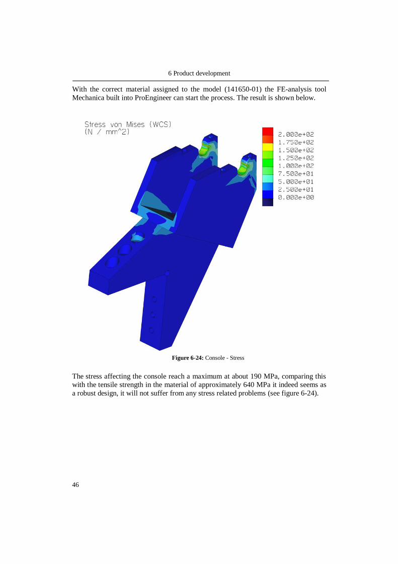
6 Product development
46
With the correct material assigned to the model (141650-01) the FE-analysis tool
Mechanica built into ProEngineer can start the process. The result is shown below.
The stress affecting the console reach a maximum at about 190 MPa, comparing this with the tensile strength in the material of approximately 640 MPa it indeed seems as
a robust design, it will not suffer from any stress related problems (see figure 6-24).
Figure 6-24: Console - Stress

6 Product development
47
A quick look at the displacements once again confirms the structural integrity, with a maximum displacement of 0,17 mm it is obvious that this will not affect normal
operation. The conclusion of this analysis is that the console is of robust design and
maybe slightly over-sized since the brackets also will contribute to an increased stability (see figure 6-25).
Figure 6-25: Console - Displacement

6 Product development
48
6.7.2 Disc spring shaft
The shaft in the disc spring solution will hold the load of the entire unit when it exceeds the pre load force. Therefore it is important to analyze this part for potential
weaknesses. The following constraints are applied (see figure 6-26):
1 - Contact surface (zero displacement around entire flange, contact with disc springs)
2 - A maximum load from the system ( 57750 N / 2 = 28875 N )
2
1
Figure 6-26: Shaft - Constraints

6 Product development
49
Once again the Mechanica module is used rendering the following stress analysis:
With the maximum stress reaching approximately 180 MPa the comparison with the tensile strength reveals a structural integrity which can carry the load without
problems (see figure 6-27).
Figure 6-27: Shaft - Stress

6 Product development
50
The displacements are as small as 0,022 mm for the maximum deflection, a good result showing that the part is robust and can handle the specified maximum loads
(see figure 6-28).
6.8 Conclusions and reflections By using the methodology provided by Ulrich and Eppinger the work is structured
and the different steps makes the concept generation phase less complicated. By
setting up the list of metrics and the target specifications in combination with a
decomposition of the problem into three sub problems the search for concept solutions becomes more efficient. The concept selection uses a ranking system based
on the target specifications which makes it easier to eliminate concepts that do not
possess the right properties.
In this case there are two solutions left for the linear motion sub problem, one of these
is eliminated as soon as some further investigation is made. In the ideal case it would
be preferable to have more than one candidate when the final concept selection is
made, but since the section owner and the technical specialists are updated continuously the decision to choose the electromechanical cylinder was well
approved.
Figure 6-28: Shaft - Displacement

6 Product development
51
For the elasticity problem there are three concept solutions available after the first
concept selection, the servomotor control concept is disregarded when it is clear that it will not work. It is established that the break pin concept cannot work by itself but
only in combination with another elasticity solution and that it brings parameters to
the system which are hard to control (material properties, difficult engineering problems etc.). With the base in these statements it is decided that the break pin
concept is removed from further studies but also that it can be analyzed further if
needed in future development.
This need for a break pin solution can arise if the length of the unit is a critical factor, in that case it is possible to redesign the disc spring solution to include a break pin
that will handle the large overloads (full wrap-around, ozone pipe conk out etc.) while
the disc spring system takes care of the small variations (paper splice, solid pieces of polymer etc.). The disc spring concept is analyzed further and finally it is approved to
be the final concept selection.
Designing the console concludes the concept generation and selection process and together with the establishing of the final specifications and the FE-analysis the
concept solution is verified and approved by the section owner and the technical
specialists.


53
7 Results and conclusions
Based on the analysis and the disadvantages as described in chapter 4, the hydraulic
system has many weaknesses and there are many benefits to be achieved by replacing it with a servomotor solution. The solution described here is able to meet all
requirements and may also contribute with additional features specific for a
servomotor solution for example increased controllability and the possibility of changing parameters during operation to fine-tune the process. The servomotor
solution has the potential of replacing the hydraulic system completely and will help
modernizing the nip unit to comply with future demands.
The electromechanical cylinder is a high precision unit made for large loads and
tough environments. Connected with a servomotor in a parallel configuration it is
both compact and robust, it is also well protected for usage in a tough environment. It
is able to produce a nip pressure slightly above the required level and it will move the nip roller with great precision. The ambition is to control the unit by measuring the
load between the unit and the nip roller bearing housing with the help of a load cell
connected to the disc spring package. When thoroughly tested it may be possible to control the unit simply by measuring the torque inside the servomotor and removing
the load cell, this has to be analyzed further.
The disc spring package can accumulate the load equivalent to an ozone pipe conk out as well as small load deviations. Since the package is preloaded the system will
have full precision at normal operating pressure, it is also possible to adjust the
preload on the disc spring housing if required. The design provides good protection
for moving parts and keeps dirt and dust away from the springs, which otherwise could cause problems since the disc springs are depending on a low friction contact
with the guide (which in this case is the housing). If different characteristics are
desired there are many ways of configuring the disc springs to achieve various force/deflection ratios.
To be able to mount the new servomotor solution in a correct way the console is
designed with the intention of creating a robust unit which is easy to assemble.
Though maybe slightly over-sized the console provides a strong base for attaching the new unit, this is important to achieve good performance.
Overall the servomotor solution seems potent and is a good alternative for replacing
the hydraulic cylinders. Requiring only small modifications it can easily be mounted onto existing equipment reducing costs for reconstruction significantly.

7 Results and conclusions
54
7.1 Suggestions and recommendations In the case the unit length exceeds the space available there are alternatives to investigate further. The first alternative is to combine a smaller disc spring package
with a break pin solution. By doing this the smaller disc spring package will handle
the small loads such as overlap splices, solid pieces of laminate etc. while the break pin will release the system for extreme overload situations such as extensive
wrap-around, ozone pipe conk out etc.
The other alternative is to place the electromechanical cylinder and servomotor
beneath the nip roller system with the help of a lever arm, this alternative require extensive modification to the nip unit and needs to be analyzed thoroughly before
implemented.
In the case of choosing between SKF and Exlar the choice to use the SKF unit in this thesis was made mainly because of the amount of assistance that they supplied during
the project and because of the fact that their unit was slightly shorter than the Exlar
offer. SKF also showed interest in understanding the process and all possible problems that can occur and therefore their offer seems more reliable.

55
Appendix A: References
Books/articles
Eppinger, Steven; Ulrich, Karl, 2003, Product Design and Development, McGraw-
Hill, USA
Skytte, Lena, 2009, New generation nip equipment specification_Issue 3
Internet
PMC Hytech www.pmchytech.com [2010-03-17]
New World Encyclopedia www.newworldencyclopedia.org [2010-04-13]
Lesjöfors AB www.lesjoforsab.com [2010-01-25]
Schnorr www.schnorr.com [2010-01-26]


57
Appendix B: Linear actuators - Comparison Data

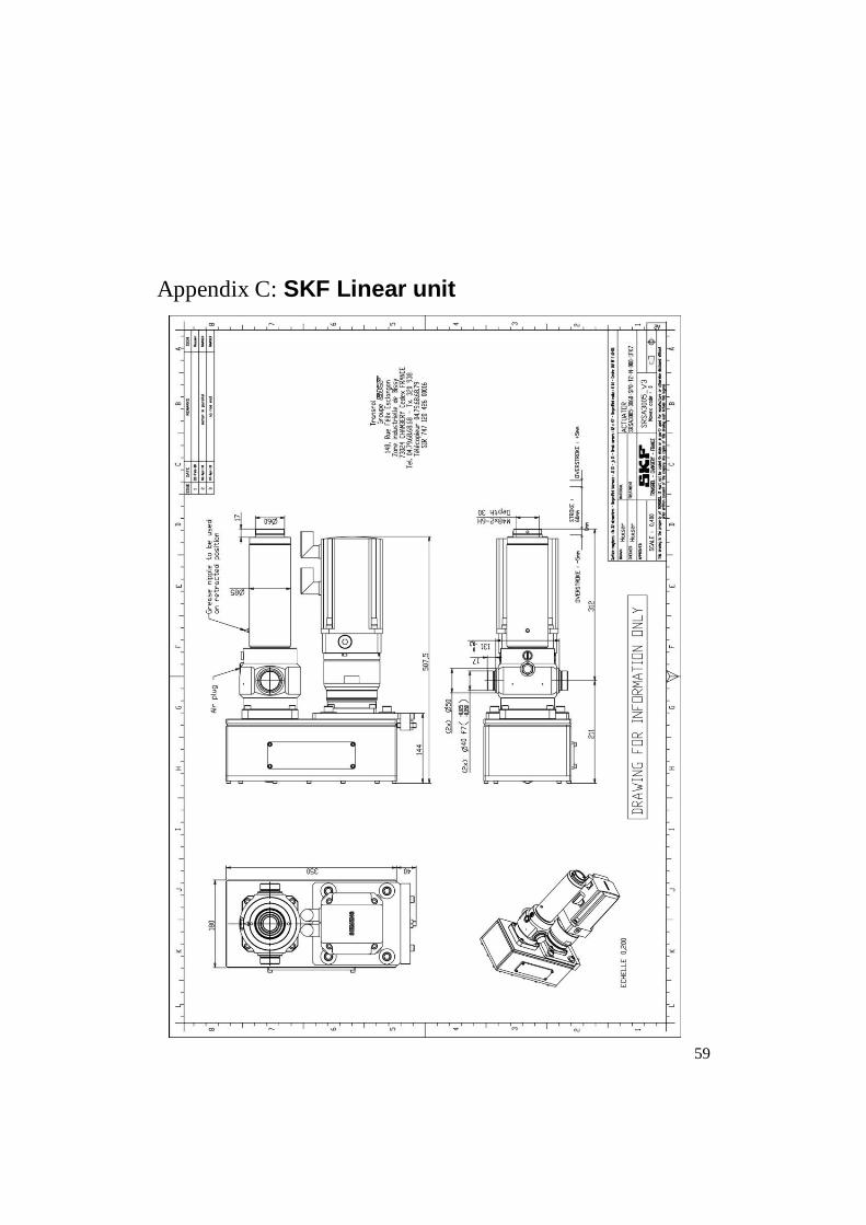
59
Appendix C: SKF Linear unit


61
Appendix D: Kistler load cell

62

63


65
Appendix E: Lesjöfors disc spring package
Disc Springs, Data Sheetgroup 2
part./drawing no.: 18 0126
Version 19.7.98 project:
2010-05-28 Muhr und Bender, Tellerfedern und Spannelemente GmbH, Postfach 120, 57564 Daaden
phone.: sales: 02743/806-184, -194, Fax.:-188; engineering: 02743/806-268, -236, -131, Fax.: -292
characteristic of stack
dimensions
outer diam.: De= 150,000 mm
inner diam.: Di= 61,000 mm spring-
thickness: t= 5,000 mm load
red. thickness: t'= 5,000 mm in N
spring height: l0= 10,300 mm
data h0= 5,300 mm
h0/t= 1,060 h0'= 5,300 mm
h0'/t
'= 1,060 De/Di= 2,459
stack: 32 springs as travel in mm
16 pacets 2 times stacked
load points calculated load points
of one spring stresses of stack
s/h0'
load- height l travel s load F s I s II s III s OM height l travel s load F
point mm mm N MPa mm mm N
0% 0 10,300 244,800
37% 1 8,328 1,972 20625 -1408 215 657 -500 213,243 31,557 41250
65% 2 6,875 3,425 28875 -2271 548 1045 -869 189,994 54,806 57750
39% 3 8,240 2,060 21257 -1464 231 683 -523 211,840 32,960 42514
Flat 5,000 5,300 35207 -3165 1196 1426 -1345 160,000 84,800 70414
specification
material: 50 CrV 4 Youngs-modulus: 206000 MPa
surface finish: shot peening temperature: 20 °C
corrosion prot.: phosphated and oiled
fatigue life of Mubea springs please contact Mubea!
more than 15 pacets!
travel: 23,25 mm between l 1 : 213,24 mm and l 2 : 189,99 mm
remarks
Load tolerance: +10 / -5% at 75% of h0 of one spring
tolerance inner diam.: 61,000 mm to 61,300 mm
tolerance outer diam.: 149,600 mm to 150,000 mm
0
10000
20000
30000
40000
50000
60000
70000
80000
0,00 20,00 40,00 60,00 80,00 100,00
t’
II
I
h 0 l 0
D i
D e
I II
Mubea