neutro - vokera ltdvokera.co.uk/wp-content/uploads/2009/04/neutro-installation-and... · 2.2.2 roof...
TRANSCRIPT

Installation
& Servicing
Instructions
THESE INSTRUCTIONSTO BE RETAINEDBY USER
Vokèra is a licensed member of the Benchmark schemewhich aims to improve the standards of installation and commissioning of domestic hot water systems in the UK.
NeutroWood pellet boiler

Dear Customer First of all we would like to thank you for the trust you have placed in us when purchasing one of our products. We have prepared this short manual for you in an attempt to make it as easy as possible for you to use our product. We also advise you to show the specific technical information given on the following pages to those in charge of assembling the unit and making the product operational so that these operations can be carried out as correctly as possible.
LIST OF CONTENTS
Chapter 1 Introduction 1.1 Product size and construction features 1.2 Product technical features 1.3 Fuel features Chapter 2 Installation 2.1 Indoor positioning 2.2 Fume extraction flue features 2.2.1 Outside wall extraction 2.2.2 Roof extraction by means of traditional flue 2.3 Hydraulic connection features 2.4 Control board wiring diagram 2.5 Product covering assembly instructions Chapter 3 Use of the product 3.1 Control panel 3.2 Lighting for the first time 3.3 Conditions for use 3.4 Safety devices 3.5 User menu 3.6 One‐way radio control Chapter 4 Maintenance 4.1 Scheduled maintenance 4.2 Yearly maintenance 4.3 Unscheduled maintenance 4.4 Troubleshooting

These instructions cover the basic principles to ensure the satisfactory installation of the stove, although detail may need slight modification to suit particular local site conditions. In all cases the installation must comply with current Building Regulations, Local Authority Byelaws and other specifications or regulations as they affect the installation of the stove.
It should be noted that the Building Regulations requirements may be met by adopting the relevant recommendations given in British Standards BS 8303, BS 6461 and EN 12391‐1 (replacing BS 7566 which has been withdrawn) as an alternative means to achieve an equivalent level of performance to that obtained following the guidance given in Approved Document J.
Please note that it is a legal requirement under England and Wales Building Regulations that the installation of the stove is either carried out under Local Authority Building Control approval or is installed by a Competent Person registered with a Government approved Competent Persons Scheme. HETAS Ltd operate such a Scheme and a listing of their Registered Competent Persons can be found on their website at www.hetas.co.uk.
PREAMBLE We would like to help you understand our manual by listing briefly the meaning of the symbols characterising the most important and significant information given:
Warnings and safety
Important information The manufacturer declines any liability for any damage caused to people or property because of failure to observe the simple rules of installation and use, described in this manual. You are also reminded that in installing the product you must observe relevant national and local building regulations. In pursuing continuous improvement of its products and customer satisfaction, the manufacturer reserves the right to make all necessary modifications to improve the quality level of its products, without prior notice.

1. INTRODUCTION
1.1 PRODUCT SIZE AND CONSTRUCTION FEATURES We show below the main dimensions of the pellet heater.
Typical Dimensions Height 1015 mm Width 580 mm Depth 585 mm Weight 230 kg Fume outlet diameter 80 mm Air intake diameter 45 mm Water pipe diameter ¾” Tank capacity 28 kg Boiler capacity 10 litres
Figure 1.1. : Product size

1.2 PRODUCT TECHNICAL FEATURES
Our products are in conformity with BS EN 13240/2001 (solid‐fuel household equipment) and subsequent amendments, and already in line with the draft of European standard BS EN 14785 (pellet‐heating household equipment). They are also in accordance with legal provisions, that incorporate the following directives: ‐ 89/336 EEC (EMC directive) and subsequent amendments; ‐ 73/23 EEC (low voltage directive) and subsequent amendments; ‐ 89/106 EEC (fitness for use) and subsequent amendments. Below is a short and simple note on the main performances and fittings of our product:
PERFORMANCE Min 4.7 Rated heat input [kW] Max 14.5 Min 3.5 Overall heat output [kW] Max 11.9 Min 3 Output to heating system [kW]
Max 10.3 Min 0.5 Output Direct to room [kW] Max 1.6
Start‐Up 352 Power requirements [W] Rated 154
Maximum working water pressure [bar]
2
Maximum temperature inside the boiler ( °C)
80
Combustion gas temperature ºC 170 Mass flow of gases burnt [g/s] 14.8 Minimum draught [Pa] 10 CO values [%] < 0.04 Max. heatable volume [m3] 320 *
Min 73.5 Overall efficiency [%] Max 81.5
Min 1 Pellet consumption [kg/h] Max 3.1
at nominal flow 9 Autonomy [h] at minimum 28
Boiler capacity [litres] 10
MAIN FITTINGS Controlled combustion system with fume temperature recovery Serial Fume draught control pressurestat Serial Dual combustion system Serial Airtight chamber operation Serial Self‐cleaning glass Serial One‐way radio control Serial Automatic relighting in the event of blackout Serial Possibility of setting power (5 levels) Serial

Weekly programmer Serial Two‐way radio control Optional GSM module Optional * values calculated on the basis of act 10/91 for rooms with thermal requirement of 30 kcal/hm3 and height of 3 m. The data given above are approximate; the producer company reserves the right to make any change in order to improve the product’s performance. The results in the table were obtained using certified pellet based on Austrian and German standards DIN 51731, DIN PLUS and ÖNORM M 7135. You are reminded that the ESC (European Standardisation Committee) is in the process of defining future European technical standards that will govern both the technical features of this fuel and the economic and environmental aspects associated with the production line.
1.3 Fuel features
The main feature of this heater is that it burns a natural fuel (the pellet) obtained in an environmentally‐friendly way from scraps of the timber industry (wood chippings, sawdust, etc.). Wood chippings and sawdust from wood products, after having been duly re‐cleaned and dried, are compacted in state‐of‐the‐art very high‐pressure plants, into pure rounded wood pieces: the pellet. Each rounded piece can have variable lengths and thicknesses, respectively between 1÷3 cm in length and 6÷8 mm in diameter. The pellet’s main features are low moisture content (below 12%), its high density (=600 kg/m30 as well as its regularity and compactness that give this type of fuel characteristics of high calorific power (I.C.P. 4000÷5000 kcal/kg).
Figure 1.1: Wood in pellet form.
The pellet to be used to feed the heater must have high quality characteristics such as, those defined by standards DIN 51731 and ÖNORM M 7135, some basic details of which we set out below. Quality standard for wood in pellet form
Unit of measurement
Önorm M7135
DIN 51731
DIN plus
Diameter Mm from 4 to 10 from 4 to 10 from 4 to 10 Length Mm 5 x D1 < 50 5 x D1
Density Kg/dm3 >1,12 1,0 /1,4 > 1,12 Moisture Content % < 10 < 12 < 10
Ashes % < 0,50 < 1,50 < 0,50 Calorific Power Kwh/kg > 5 4.86 / 5.42 >5
Sulphur % < 0,04 < 0,08 < 0,04 Nitrogen % < 0,3 <0,3 <0,3 Chlorine % < 0,02 <0,03 <0,02 Powders % weight <2,3 ‐ <2,3

Binding agents % of pressed mass <2 2 <2
1 Not more than 20% of the pellet may have a length greater than 7.5 times its diameter D. 2 The DIN prohibits the use of any added substance. However, this prohibition is not valid for small heating systems.
DIN plus proposes the combination of the qualitative parameters proposed by standard DIN 51731 and by Austrian standard Önorm M 7135.
The pellet, as also stipulated by current Italian legislation governing the commercial technology characteristics of fuels (DPCM 2.10.1995) must be produced exclusively with untreated wood chippings, with no other added materials.
It is strictly prohibited to use any solid or liquid fuel other than the pellet to feed the stove.
In order to optimise the use of the product we recommend using pellets which have been given a quality certificate by an authorised body. The use of pellets other than those directed by the installer may lead to heater malfunction and to the guarantee becoming invalid.
Storing and even moving the pellets are important operations to be carried out with care: • The fuel must be stored in a dry place away from cold; • The pellets must be moved so as to avoid excessive crumbling into fine dust.
Observance of these two simple rules makes it possible both to obtain better fuel efficiency and to preserve the mechanical moving parts of the apparatus.
If the product is kept out of service for long periods of time (over fifteen days), the tank must be emptied of any residual fuel, in order to prevent any excessive dampness of the fuel causing the product to malfunction.

A high moisture content in the pellet may cause it to crumble into dust, that creates a greater accumulation of residue in the brazier area and blockage of the fuel feed system (auger).
2 INSTALLATION INS.
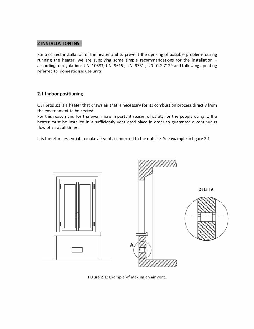
For a correct installation of the heater and to prevent the uprising of possible problems during running the heater, we are supplying some simple recommendations for the installation – according to regulations UNI 10683, UNI 9615 , UNI 9731 , UNI‐CIG 7129 and following updating referred to domestic gas use units. 2.1 Indoor positioning Our product is a heater that draws air that is necessary for its combustion process directly from the environment to be heated. For this reason and for the even more important reason of safety for the people using it, the heater must be installed in a sufficiently ventilated place in order to guarantee a continuous flow of air at all times. It is therefore essential to make air vents connected to the outside. See example in figure 2.1
Detail A
Figure 2.1: Example of making an air vent.

In compliance with the indications reported under regulation UNI 10683 , the air inlets must have the following features :
1.They must have a clear space of not less than 80 cm2; 2.They must be made at a height close to the floor; 3.They must be suitably protected by a wire mesh or grille in such a way that the minimum passage space is not and may not be reduced; 4.They must be placed in such a way that they are not obstructed in anyway.
The correct inflow of fresh air may be guaranteed by using apertures towards an adjacent room, provided that it has direct ventilation, and it is not an environment with a fire hazard, such as store‐rooms, garages or warehouses, as regulated by regulation UNI 10683
Our heater should be installed in rooms where there is no equipment operating in airtight conditions in relation to the room, or apparatus that may place the room itself in a vacuum in relation to the outside environment and thus cause problems of poor draught for our product ( regulation UNI 10683).
Combustion products from our heater must not be extracted into shared flues. When checking equipment compatibility, it is good practice to check whether the support plane (floor) has a bearing capacity (kg) that is suited to the weight of the product it must sustain. If not, correct safety measures must be taken (eg. Load‐distribution plate). When installing the heater, it is advisable to plan a suitable distance from the walls of the room in order to provide any access necessary both in the rear (at least 20 cm is recommended) and to the side of the product (80 cm is recommended) (for example to carry out appropriate cleaning work correctly).

Having placed the outermost overall part of the heater at a distance of 80 cm from combustible and/or flammable material, if this distance cannot be maintained it is useful to arrange for heat protection to be provided ( regulations UNI 7129 , UNI 10683)
Do not get close to, and above all do not touch with flammable material the outer surfaces of the combustion chamber that, after continuous product use, may reach high temperatures .
Once the installation has been completed , pay attention in placing the power switch in a position which will allows an easy and comfortable access. If the floor is made of combustible material (eg. parquet), it is advisable to protect it using a sheet of non‐combustible material placed underneath and around the heater.
Figure 2.2: Positioning distances .

2.2 Fume extraction flue features The main features characterising the fume extraction flue are given. They are based on what is set out in standards UNI 7129 and UNI 10683/98: ‐ Inspection valves (I); ‐ Minimum height of the pipe directly connected to the heater fume extraction outlet
must be between 2 ‐ 3 m; ‐ If it is necessary to have a horizontal section, it is advisable to make it with a maximum
length of 1.5 m and with an incline of 3 ‐ 5% in order to help the fumes to escape; ‐ Use of a cowl that is wind‐resistant and rain‐resistant in order to avoid a change in the
slight condition of overpressure the flue is in, (it is strongly recommended not to use a horizontal section at the end of the flue).
The reduction in pressure in the flue is necessary so as to help the normal flow of fumes from the combustion chamber towards the outside, in the event of a mains power cut.
Remember that excess heat disposal is managed in an optimum way from the electronic control panel (modulation, switch‐off stage, etc.).
‐ Flues must be made of appropriate materials to resist combustion products and
condensation ( the inspection valves should allow to discharge possible condensation) ‐ The flues must be manufactured in order to insure the maximum smoke resistance
(regulation UNI 10683/98) ‐ Duct insulation particularly on the outside part exposed to the weather.
Avoid making completely horizontal sections.

Figure 2.3: Fume extraction flue
In the room where the heat generator must be installed, there must be no fume‐ extraction hoods already in existence or installed, in order to avoid depressing the atmosphere.
The air vents must not be closed.
Keep the flue clean, performing a cleaning operation at least once a year; it is also advisable to clean both the flue cowl and the fume pipe connection.

2.2.1 Outside wall extraction One of the installation solutions that may be adopted is that of placing the pellet heater close to an outside wall of the room so that the fumes are extracted directly to the outside (figure 2.4). Hereafter please find some recommendations reported under regulation UNI 7129 referred to this particular plant: ‐ Always guarantee that there is an inspection valve (I) that will allow effective and
periodic cleaning to be carried out, and any condensation formed to be eliminated; ‐ The cowl (T) must be strictly windproof and rainproof; ‐ Insulate the fume extraction flue appropriately in the section where it goes through the
wall. The fume extraction flue that is completely outside must be made of double‐wall stainless steel in order to guarantee that there is both greater resistance to atmospheric agents and correct fume extraction temperature.
Figure 2.4: Outside wall extraction

2.2.2 Roof extraction by means of a traditional flue Pellet combustion fumes may be extracted also using a pre‐existing traditional flue (figure 2.5), provided that it is made to standard (refer to standard UNI 10683). Below is a short list of some of the main features given in the standard that characterise a good chimney (C): ‐ Suitable insulation and proofing particularly in its outer section that is exposed to the
weather; ‐ Uniform internal section (there must be no section restrictions); ‐ Made of material that is resistant to high temperatures, the action of combustion
products and the corrosive action of any condensation formed; ‐ Predominantly vertical course with deviations from the axis of no more than 45°; It is advisable to provide for a chamber to collect solid matter and any condensation (R) that can be inspected by means of an airtight window (I).
Figure 2.5: Extraction by means of a traditional flue.

We recommend to follow indications reported under regulations UNI 9615 and 9731 referred to dimensions of the chimney ( C ) and however to avoid using sections smaller than 100 mm . In the case where there are larger sections, it is necessary to insert a steel pipe (A) inside the masonry one (C), as shown in figure 2.6.
The steel flue pipe must be suitable insulated with a high temperature‐resistant rock wool or vermiculite material (B).
Figure 2.6: Example of extraction flue connection.
In the case of fire in the extraction flue or duct, switch off the heater immediately and disconnect it from the house mains power supply.

2.3 Connection to Central heating system In order to be able to operate, the heater must be suitably connected to a heating system. For this type of installation also, some simple suggestions are provided that will undoubtedly be helpful when installing the product (refer to regulation UNI 10412 and following up‐dating)
The drainage cock is placed at the lowest point of the water circuit.
We recommend to install the ball valve on the delivery water pipe and on the return water pipe ( please refer to the enclosed schematic drawing) . This will enable a quick and easy maintenance operation in case of need.
All water heating installations should be designed, before product installation, and installed by a competent heating engineer in accordance with BS 5449: 1990; Code of Practice for Central Heating Systems for Domestic Premises. Further guidance is available from the following sources: BS EN 14336: 2004 Heating Systems in Buildings. Installation and commissioning of water based heating systems. BS EN 12828: 2003; Heating Systems in Buildings. Design of water based heating systems. BS EN 12831: 2003; Heating Systems in Buildings. Method for calculation of the design heat load.

The ball valve mounted on the inlet pipe must be open in normal system operating conditions in order to allow water to be added to the boiler. It may be closed when it is necessary to drain the system.
The delivery and return pipes have a diameter of ¾".
The correct functioning of the “ expansion box open ” requires that the expansion box is placed at a height not less than 7 meters in respect to the stove.
The expansion vessel must be made of a covered vessel located above the highest point reached by the water in the system. The safety, inlet and outlet pipes must be protected from ice where this may occur. The safety pipe must allow the highest part of the generator to be in contact with the atmosphere and not have reverse gradients, except for the section intended to lead into the upper part of the expansion vessel. The inlet pipe must allow the lowest part of the generator to be in contact with the lowest part of the expansion vessel and must not have reverse gradients capable of preventing circulation by gravity in the circuit (safety and inlet pipes, stove, expansion vessel). The outlet pipe in contact with the outside must have a section at least equal to that of the safety pipe. The overflow pipe may also be used as an outlet pipe provided that it has a section not smaller than that of the safety pipe.
Our generator must not be mounted inside closed expansion vessel circuits. 2.4 Control board wiring diagram
For general purposes, the diagram of the control board input and output connections is given. This diagram is expressly intended for the technical personnel in charge of installation and maintenance.

For mounting our product parallel to a traditional gas boiler, according to the diagram shown it is necessary to connect a three‐way valve on the same pins (15 and 16) used for the recirculation pump.
M
Figure 2.9: Control board wiring diagram
2.5 Instructions for mounting product covering For mounting the outer covering, simple instructions are provided: 1. Use a crosshead screwdriver. 2. Lift the top (1) , remove the two screws holding the display .
Take care when moving the top in order to avoid damaging or disconnecting the flat connecting cable between the board and the display

3. Lift the side panel on the right hand side ( 2) . 4. Repeat the same process on the left hand side . 5. Dismount the lower panel ( 3) remove the screw placed on the base of the front door , remove the carter .
Figure 2.10 : Pellet heater – instructions for mounting product
5. For some models it might be necessary to lift and move the sheet‐metal top of the heater sideways in order to insert the side majolica tiles.
3.0 MAINTENANCE
3.1 SCHEDULED MAINTENANCE It is necessary to perform periodic maintenance of the heater in order to ensure constantly correct and effective operation.

The cleaning operations described below must be carried out only when the heater is totally cold and disconnected from the household mains power supply.
Disconnection from the household mains power supply is obtained by means of two simple operations: the first consists of turning off the switch placed at the back of the heater and the second of removing the product power cable (from the socket on the wall or from the rear of the apparatus).
Figure 3.1: Pan grille The grille at the base of the pan (figure 3.1) is cleaned automatically during the heater extinguishing stage in order to ensure at all times the correct inflow of burning air in the combustion chamber. Should residue pellet accidentally remain, remove it by hand or with the brush.
THE BURNING PAN MUST NOT BE TEMPERED OR MODIFIED. The ash drawer at the base of the pan must be cleaned every time the fire is lit, whereas the “ash box” may be vacuumed not at the same time but however very frequently. The stove is equipped with tie‐rods which ensure to clean the residuals which unavoidably will deposit on the outside of the exchange pipes . This operation is completed by using the two tie rods placed on the top of the stove and are accessible by opening the pellet tank lid ( figure 3.5.). Lift and release several times until the operation becomes smooth‐running.

By cleaning the surfaces of the exchanger pipes, the best possible heat exchange is always guaranteed.
Figure 3.2. : Pellet loading
When loading the pellet , the pellet must not fall into other areas than those designated for this purpose. A check should be made of the gaskets that ensure that the combustion chamber is airtight in order to prevent excessive wear and tear from causing irregularities in the combustion process. Open the window and check that the gasket which ensures that the combustion chamber is closed tight is unbroken.
The frequency with which to perform the scraping operations depends, as in the case of cleaning the glass, on the intensity of use of the apparatus. In normal usage conditions (eight hours a day), we recommend this operation be performed at weekly intervals.

Figure 3.3.: Fire door gaskets
It might be necessary , at regular intervals , to clean the glass because it inevitably becomes dirty . Although this is a natural phenomenon , the frequency with which it occurs depends on the size and quality of the fuel used.
Clean the glass when completely cold and using normal , non- abrasive detergents.
Figure 3.4. : Ash trays
The above illustration has the scope of illustrating the ash tray systems for maintenance and cleaning of the same. The system can be reached by dismounting the front panel .The front

panel itself is dismounted by loosening the screw positioned right in front of the burning pot ; the opening of the tray system is reached by removing the wing screws . Once the cleaning process has been completed and all the ashes have been removed by vacuum or by using the specific brush delivered together with the stove, all trays must be replaced and well tightened .
The above cleaning process should be achieved using the specific cleaning brush supplied with the stove or a vacuum cleaner. At the end of the winter, we recommend emptying the fuel tank of residue pellet and storing it according to the methods suggested in chapter one.
We recommend a thorough cleaning of both the flue and the fume junction (at least once during the whole operating season) in order to prevent fire risks.
3.2 Yearly maintenance This paragraph, intended expressly for engineers and all specialised personnel required to work on our product, is aimed at providing useful instructions in order to perform the necessary work for keeping the apparatus operating at a high level of efficiency.
Unscheduled maintenance of the system must be carried out by qualified personnel when the heater is cold and disconnected from the household mains power supply.
In all cases where the maintenance described in the previous chapters is insufficient (irregular operation of the apparatus, poor efficiency, excessive fuel consumption) and more generally once every two years, it is necessary to have an engineer perform a more thorough cleaning of the parts of the apparatus in most direct contact with the thermo vector liquids. The stove is equipped with side inspection slits . The two slits on the sides of the apparatus (one on each side) that allow access to the area of the set of pipes in order to perform a more thorough cleaning of these pipes. These access holes can be reached only after having lifted the top and after having removed the side inserts in ceramic material. In order to lift the top ceramic tiles, it is necessary to remove the grille and the display housing. When the whole top part of the heater has been removed, the side inserts can be carefully pulled out.

Figure 3.5. : Slide slits
The slit will only be visible after its cover has been removed. Now it is possible to perform the cleaning, using the brush. Every 2 years it is necessary to clean the steel fan of the fume extractor and its housing. This part can be reached after having removed the side ceramic panels and after removing the four screws that hold the fan. The cleaning can be performed more easily with a vacuum cleaner.
In this model the heat exchangers can be reached by means of the openings positioned at the rear of the stove. When replacing the covers of the side slits it will be necessary to remove the rear panel by loosening some screws. When replacing the parts and components , we would recommend the use of , we recommend sealing by high‐temperature silicone ( heat resistant at 700°C).
For the supply of any spares, we recommend you contact the assistance centres for further information and advice on products to purchase.
When replacing the covers of the side slits, we recommend sealing the closure in order to guarantee air tightness, using for example non‐refractory high‐temperature silicone.
3.3. ASHES

It is necessary to perform periodic maintenance of the ash box and the pan grille . The cleaning operations must be carried out only when the heater is totally cold . Should residue ashes accidentally remain , remove with a brush of a vacuum cleaner.
With the aim to guarantee to the customer a perfect and long‐lasting running , we have limited the use of mobile components thus limiting the possibility of undersigned air infiltration within the combustion chamber which could cause irregularities in the combustion process.
3.4 TROUBLESHOOTING
This paragraph has been designed to give the purchaser of our product a quick and effective means of understanding any problems that may arise when using the heater. If these possible solutions do not apply to the operating defect you have experienced, please call the customer service centre for further information.
Problem found Possible cause
The display does not light even after having pressed the “on” button
‐ The heater is disconnected from the mains power supply.
‐ Temporary cut in power supply. ‐ Electrical or electronic problem on the board. ‐ The general switch at the rear of the heater could be off.
Repeated failures to light
‐ Incorrect operation of the burning air intake system (fumes fan).
‐ Existence of a possible obstruction of the burning air inlet to the pan or holes in it.
‐ Electrical or electronic problem on the board. ‐ Primer resistance or the fume control thermal probe could be faulty.
‐ Door not tightly closed
‐ Existence of a possible obstruction of the burning air inlet to the pan or holes in it.
‐ Incorrect operation of the burning air intake system (fumes fan). ‐ The fuel could be too damp.

The pan fills with fuel
‐ Door not tightly closed. ‐ Primer resistance or the fume control thermal probe could be faulty. ‐ Electrical or electronic problem on the board.
Stove in modulation status o with continuous variations to water temperature in the boiler or unexpected extinguishing of the flame
‐ Check the position of the two‐way remote control unit and with special attention in the event that the sensor of the remote control unit is positioned in a warm area ; ‐ Check the temperature fume temperature and check that the flues have been correctly installed;
‐ Check that the boiler temperature detecting probe is not faulty ;
‐ Check the functioning of the circulator Unexpected lowering of the flame ‐ Pellet hopper almost empty.
‐ The auger could be closed. ‐ The flue could be obstructed. ‐ Electrical or electronic problem on the board.
4. USE OF THE PRODUCT Before describing in detail the operation of the product, we wish to remind you that, in using it, you are obliged to observe current national and local regulations. For better understanding of the way the product operates, diagrams are provided, together with a detailed description of the control panel and the method of programming the product, as well as operations to be performed in order to light the heater for the first time. It is very easy to light the heater , after having connected it to the household mains power supply, by pressing the ON/OFF button.
When lighting the heater for the first time, fumes and odours may be emitted from the painted parts. These problems are intrinsic to the chemical stabilisation process of the special paint used, and so at this stage the room must be well‐aired.
It is strictly prohibited, under penalty of the guarantee becoming invalid, to start the heater without having connected it to a suitable water system.
You are reminded that the product must operate with the heater door always closed.
Although the surface temperatures reached by our product are not so high, we recommend you pay due care and attention when touching them. In particular, the outer surfaces of the combustion chamber may get red‐hot after intense use.
Having placed the outermost overall part of the heater at a distance of 80 cm from combustible and/or flammable material, if this distance cannot be maintained, arrangements should be made to provide heat protection (UNI 7129, UNI 10683).
In order to prevent the occurrence of malfunctions that could in turn be a source of possible damage to persons or property, we recommend avoiding lighting and extinguishing the product suddenly and continuously, but rather for these operations following the time schedules set out by the builder.
We recommend a thorough clean both of the flue and of the fume junction (at least once a year) in order to prevent fire risks.
We would remind you that the product must operate with the ash tray hermetically sealed.
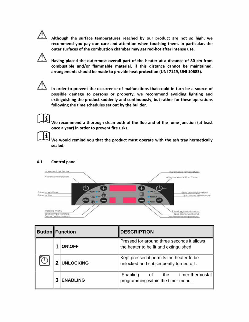
4.1 Control panel
Button Function DESCRIPTION
1 ON\OFF Pressed for around three seconds it allows the heater to be lit and extinguished
2 UNLOCKING Kept pressed it permits the heater to be unlocked and subsequently turned off .
3 ENABLING Enabling of the timer-thermostat programming within the timer menu.

1 MENU Allows access to the menu mode at any time.
1 POWER MODIFICATION
Increases the operating power level . In menu mode its allows scrolling through menus and submenus.
2 SCROLLING THROUGH MENUS AND SUBMENUS
In menu mode it allows scrolling through menus and submenus
1 MODIFICATION TO AMBIENT/BOILER THERMOSTAT
Increase and decrease the thermostat setting value when not in menu mode.
2 MODIFICATION TO MENU SIZES
In modify menu mode it allows the menu and submenu sizes to be varied
Button FUNCTION DESCRIPTION
1 TIMER-THERMOSTAT Pressed for three seconds it permits the programming to be enabled and disabled
4 ESC Allows exit from a menu or a submenu
1 SET
Allows : ‐ when not in menu , pressed for three seconds it
allows to vision the sizes; ‐ Allows entrance to the submenus ‐ Allows entrance and modification to the menu ‐ Allows to save all data
4.2. BUTTONS Each button is associated to one or more functions as indicated within the under reported scheme :
SYMBOL
FUNCTION DESCRIPTION
ON/OFF Light off : heater not running Light flashing or on : heater running
1. IGNITOR Warning light ON : Ignitor running
2 TIMER THERMOSTAT PROGRAMMING
Warning light ON : Time schedule of lighting the heater by Timer .

1 SCREW Warning light ON : Screw is in operation
2 TIMER
PROGRAMMING Warning light ON : Time schedule of extinguishing the heater by Timer
FAN OR CIRCULATOR Warning light ON : Pump fan is active.
AMBIENT THERMOSTAT Warning light ON : Room temperature higher than the temperature set in the ambient thermostat
TIMER DAILY Warning light ON : The daily programming mode is set.
TIMER WEEKLY Warning light ON : The weekly programming mode is set.
TIMER WEEKEND Warning light ON : The weekend programming mode is set.
4.3. THE DISPLAY
Hereunder please find the different types of messages displayed on the three display panels:
1. Display superiore
2. Display inferiore sinistro 3. Display inferiore destro
1. Top display , 2. Bottom left display ; 3. Bottom right display.
1. TOP DISPLAY
READ-OUT EXAMPLE
SIZE VALUE DISPLAYED STATUS
Time With the stove OFF or on in NORMAL condition, the display shows the time schedule.

The condition of operation Error
With the stove on, it displays the condition of operation and any error that has occurred.
Menu mode Submenus modeSize values
In menu mode, it displays the name of the menus and the submenus, as well as the size values.
DISPLAY OF OPERATING CONDITIONS
DISPLAY READOUT DISPLAY READOUT
CHECK UP
This is a stage required for self‐diagnosis of the probes and for initial cleaning of the combustion chamber before the LIGHTING stage (appears on display as “CHEC”).
LIGHTING Stage during which the flame is primed
(appears on display as “Acc”).
STABILISATION
Fixed time stage in which the flame is propagated to the whole of the combustion bed before entering the stage of NORMAL operation (appears on display as “Stb”).
MODULATION
This is a stage in which combustion must be controlled in order to reduce the amount of heat transferred to the thermo convector liquid (appears on display as “Mod”). The condition of modulation is obtained if the ambient temperature reaches that set. At the modulation stage the product operates at power one regardless of the power programmed.
EXTINGUISHING
this condition can be entered manually (by pressing the ON/OFF button), automatically (as a result of programming) or due to the factors of entry into the safety condition persisting. The condition comprises an initial extinguishing stage in which the flame goes out, the residual heat is discharged and the fume temperature goes down below a preset value, and a second stage of final cleaning required to remove residue from the brazier completely (appears on display as “Spe”).

SAFTEY
This stage is entered if the temperature of the fumes exceeds a certain value. If within a preset time interval the temperature does not come under control again, the heater cuts out and them locks (appears on display as “SiC”).
LIGHTING RECOVERY
This condition is reached when not all the factors for passing on to the condition of normal operation occur (appears on display as “rec”).
LOCKING
After the extinguishing stage that has occurred as a result of operating errors or safety operations, the LOCKING stage is obtained (appears on display as “Alt”). In order to get out of the LOCKING stage, press the ON/OFF button on the control panel for 5 seconds and the system goes to the OFF condition.
STAND-BY The stand‐by mode is a temporary flame switch‐off which occurs when the heater has reached the temperature set ( air temperature or water temperature)
OTHER MSG DISPLAYED
DISPLAY READOUT DESCRIPTION
Displays the temperature probe status. When starting the heater ( check-up) it shows the temperature of one or more probes at the
minimum value (° C) or at the maximum working value of the probe . You should check if the probe is working correctly ( read-out (0°C) o in short circuit ( read-out is the max. value consented on the scale)

Er01: . The pellet tank wall temperature has reached a temperature above 85°C. or if this temperature has been reached inside the boiler. In this case the heater can be lit only when the temperature has gone below 45°C .
ERROR DISPLAYED
Message on display MEANING
Error : n. 1 with power supply
The error can also occur when the heater is switched‐off
Error : n. 2 with power supply
The safety mode can be activated only with heater OFF
Error for safety mode during fume high temperature caused by incorrect burning
Encoder Error (only with heaters with embodied encoder)
The error can be activated only when the encoder signal is not detected
Encoder error (only with heaters with embodied encoder) The error can occur caused by the encoder not able to reach the set parameter)
CLOCK error
The error could occur due to problems with the clock

Er02: The error occurs when the pressure inside the flue is above 0.3 mbar in respect to the atmospheric pressure : The pressure inside the flue MUST ALWAYS BE LOWER than the atmospheric pressure . To this respect it is important to underline that the smoke extractor installed on the heater has the function to extract the fumes from the heater and does not push them through the flue.
Er01/Er02: They occur when the detector probes , that should normally be closed , are now in an open modus caused by a safety device activated due to and event that has interrupted the circuit causing the malfunction of the probe.
Er03: This occurs when the smoke temperature , due to malfunction , goes below the normal values.
EnC0: This occurs when the smoke extractor , that is in operation and always under control , has a sudden stop during operation � = 0 rpms
EnC1: This occurs when the heater shows a different speed compared to the selected speed. It could well be that both errors are displayed at the same time, this is caused if the three cables ( i.e.: red, black and white) conveying the signal to the board are accidentally damaged or simply the cables could be deteriorated .
4.5. LIGHTING THE HEATER FOR THE FIRST TIME
We recommend that the pan is clean before beginning the procedure of lighting and that the ash tray positioned just below the pan is tightly shut.
The heater will perform in the best conditions only when the combustion chamber is airtight in order to prevent irregularities in the combustion process . Make sure that the gasket is tight and is unbroken . Air inlet should be taken only by the openings designated by the project.
In compliance with regulations BS EN 14785 and UNI 10412 regulating the installation of water heating products and with regulation UNI 10683 on wood‐fired appliances ‐ they state that the base of the flue must have a depression of 10Pa. It is therefore necessary that particular attention is paid to the fume evacuation flues . If the flue is set low and made tortuous the natural draught will be less. In this condition the inlet air to the combustion chamber of the heater will be less and this will compromise the correct combustion . The slow smoke outflow can cause in some events , a temperature increase and a modulation status of the heater .
It is possible to use different types of pellets and the heater must be adapted to the different types.

For example the clearer colour pellet has a lower ignition point , it burns quickly and in general it leaves thin ashes that could absorb damp from the atmosphere and therefore could become compact and generate problems during the following lighting.
Pellets with a darker colour , on the contrary , burns with great difficulty and requires a greater ventilation system.
In order to optimise the product using different quality pellets and different installation methods , the heater allows an appropriate method of operation of combustion and heating to be chosen according to 4 methods . the methods run from 1 to 4 . Each number corresponds to a ventilation receipt . For example method n. 1 is suitable for operating a clearer pellet and with a flue installed according to regulations ( lower ventilation required)‐ method n. 4 is suitable for a darker pellet and with a non standard flue ( more ventilation required).
At last whereas you are not able to locate an efficient combustion method , the manipulation of the parameters can be carried out by qualified engineers from Vokera Ltd . The engineers will analyze the situation and they will recommend a suitable solution for the situation .
� For a correct operation of the heater , we recommend to set power 4 or 5 during
lighting sequence and for the following few minutes of functioning .
As a further aid to the customer, the sequence of operations to perform in order to light the product for the first time is given: 1) Connect the product to the household mains power supply; 2) Press the switch at the rear of the stove; 3) Load the tank with the right amount of fuel (We recommend not filling the chute completely
but until it reaches the plate with the round holes inside the tank); 4) Load the auger by pressing the button MENU and LOAD on the submenu , until the
pellet begins to fall continuously into the pan in the combustion chamber. Repeat the sequence until the pellet is continuously fed .
Pellets must not be loaded every time the pellet tank is empty . 5) Empty the burning pot ;
In the event that the heater fails to light , EMPTY THE BURNING POT FROM POSSIBLE UNBURNED PELLET ; THE FAILURE TO PERFORM THIS PROCESS WILL CAUSE AN ECCESS OF UMBURNED FUMES INSIDE THE BURNING CHAMBER. 6) In order to light the heater, press the ON/OFF button (Button 1) for several seconds. Now the
heater will initiate the whole check‐up and lighting procedure automatically (approximately

10 min.) until the NORMAL phase is reached. Error message could be displayed during lighting sequence
Pellets must not be inserted into the pan by hand and hands should NEVER be introduced inside the pellet tank.
The door should never be opened even during a power shortage or even if there has been a lock‐out event or even again during an auger block. The user must always activate the “switch‐off” procedure and solve the problem before a new lighting process.
Extinguishing the product: Press the ON/OFF button for several seconds. The heater will initiate the extinguishing procedure according to the methods set during the design stage (the extinguishing time is variable and may go from a minimum of a few minutes up to around 35 minutes).
We recommend that you do not stop the extinguishing procedure before it has been completed in full, for example by cutting power to the product.
Precaution: if the flame is out because there are no pellets, proceed to extinguish the heater. Only when the heater is in OFF condition should you proceed to load further fuel inside the tank to start the new lighting procedure.
Pellets must not be inserted into the pan by hand.
Use the stove always with the door closed. It is only allowed to be open to perform maintenance work to the product when cold.
The firebox must not be changed.
Tampering with the apparatus, as well as use of spares that are not original, and unauthorised replacement of parts of the product, besides invalidating the guarantee, may cause malfunctions and serious danger to the safety of the users who are in direct contact with the product.

During use, do not obstruct the vent openings, that allow the combustion air to re‐circulate continuously, and the air intake located at the rear of the product.

4.5. SAFETY DEVICES The heater is fitted with some safety devices, such as:
The fume temperature detector probe: This device allows the fume temperature to be read and the effective operation of the product to be monitored continuously;
A water temperature detector probe . This allows the water temperature inside the
boiler to be read and should the water temperature should reach 85°C then the user must operate the unlock safety switch positioned in the rear of the product.
The pellet tank temperature detector probe: It detects the tank temperature
continuously and causes product operation to be locked if a certain safety limit value is exceeded;
An ambient probe: This probe enables the temperature in the room where the heater is
installed to be constantly monitored; An ambient probe installed on a two‐way remote control
It is forbidden to fail to install or to remove one of the above‐mentioned safety devices; if these must be temporarily deactivated or disconnected for maintenance work, they must be reinstalled in order to turn the product on again.
The action of one or these devices causes an error message to be shown on the display. When the messages “Alt”, that indicates the occurrence of an error, and “Spe”, that indicates the heater has been extinguished, appear on the display, a malfunction has occurred.
Possible error messages displayed are shown in the table on the next page.
The pellets thermostat and pressure safety operation is detected and managed from the control board only in the case where the heater is in operation and thus in all the conditions except that of OFF and locked.
Pellets thermostat and pressure switch errors are placed in series electrically so that if only one of these problems arises the heater is automatically extinguished and then locked.
It could occur that one or more probes are shut down or short‐circuited, and this would be detected at the Check‐up stage. Malfunctions of these probes could cause failures to light, continuous conditions of modulation or boiler or ambient temperatures unchanged over time. When these events occur, please contact authorised personnel.

Message on display
Meaning Possible causes Possible remedies
Check that air intakes are not obstructed
High temperature inside body of heater ( T> 85°C) Ambient temperature too high (
insufficient cooling inside the heater)
Er01 Pellet tank thermostat safety operation
Probe malfunction Contact assistance centre
Obstruction in fume extraction flue That that all parts of the flue are clean
and free from obstruction Er02
Pressure switch safety operation , pressure inside the flue (p> p atm
+0.3mbar) Probe malfunction Contact assistance centre
Accumulation of pellet during malfunctioning process
Heater installed and located in low temperature ambient
Er03 Software error for low
temperature of the smoke
Malfunctioning of the fume probes
Check the receipt and the variation range of the smoke temperature
readout on the display
Fume extractor fan blocked or operating at a speed different that the
set speed EnCX Error on encoder
Malfunction of detecting devices
Contact assistance centre
Fume temperature above the limit Exchange insufficient : contact
assistance centre
Obstruction in fume extraction flue Check that all parts of the flue are clear and free from obstruction
Sic Fume over‐temperature error
Probe malfunction Contact assistance centre
Shut‐down or short circuit
Sond Malfunction of measuring chain
temperature probes Probe malfunction
Contact assistance centre

4.6. FUNCTIONS FROM THE KEYBOARD
Changing the temperature value of the ambient thermostat:
Hereafter please find the instructions to change the temperature value of the ambient thermostat in non‐menu mode.
Note : The current temperature value is possible to display the thermostat temperature by pressing once only one of the buttons TEMPERATURE + or TEMPERATURE ‐. Press these buttons again to proceed to a variation of the value displayed.
PROCESS
INSTRUCTIONS BUTTON
1 It is possible to display the current temperature value by pressing once only one of the buttons TEMPERATURE + or TEMPERATURE ‐.
2 To change the temperature value of the ambient thermostat:
Press Button + or ‐
Automatic exit from the display of the temperature or from the change temperature modus
After having changed the boiler thermostat value – wait for 10 seconds in order to save the new settings.
AMBIENT THERMOSTAT RANGE
MIN (°C) MAX (°C)
10 40
How to change the combustion power function

The heater is equipped with a direct access menu ( through MENU button) to change the combustion power function .
This will allow to change the power level
This will allow to modify the temperature for the ambient thermostat
Whereas you set the ambient thermostat at a low value , this could cause the continuous modulation status .
4.6.1. USER MENU
MENUS E
T
Pressing button for three seconds you will have access the MENU.
Pressing button this allows access to the menu modes as follows:
User Menu Item
Menu Submenu Functions
DAILY
Submenu CRON . It is when the daily programming mode is set ( TIMER daily)
WEEKLY
Submenu CRON. It is when the weekly programming mode is set ( TIMER weekly)
1
Menu CRON
TIMER
Submenu CRON. It is when the weekly programming mode is set ( TIMER week‐end)

WEEK END
2
Combustion menu
3
Clock menu
4
Manual pellet loading menu
4.7. Menu cron ( TIMER)
This allows the heater automatic lighting/extinguishing intervals to be programmed. It is possible to programme the heater daily with 3 different time‐schedule programming bands .
The programming mode requires that both the lighting and the extinguishing intervals are set . The extinguishing time band must be have a setting showing a switch-off time later than that of the lighting time-band.
4.7.1. DAILY
This allows the daily programming mode and allows to programme different time‐schedule bands for each single week day. Within the same day it allows three different time‐scheme programming bands ( each band must have its ON time and its OFF time set).
The top display will show :
- Broken lines if the program has not been enabled - Time of ON and time OFF if the programme has been set.

N.B.:
When the time‐schedule ON has been set , the lower display will show:
When the time‐schedule OFF has been set , the lower display will show
The lower display will show , from left
- time‐schedule programming bands available ( from 1 to 3 );
- ON and OFF indicator
- Days of the week
The minutes scroll from fifteen to fifteen ( i.e. : 20:00 , 20:15 , 20:30, 20:45). By just setting the hour at 23 it is possible to select for the minutes from the value 45 to the value 59 so as to be able to make a programming to straddle two days (over midnight).
PROGRAMMING THE TIMER (CRON)
INSTRUCTIONS BUTTON
1 Press the button for 3 seconds and enter into Menu mode
2 Scroll through the menus and finally access to Cron (Timer)
3 Enter the Cron menu ( Timer)

4 Scroll through undermenus and finally access to Giornaliero (Daily)
5 Enter the under menu Giornaliero ( DAILY )
6
Scroll through the Giornaliero (Daily) undermenu until reaching :
- Day of the week ( form Momday to Sunday)
- Program band selected ( from 1 to 3)
- Time ON
7 Enable the pre‐selected time‐schedule by pressing the ON/OFF button for approx. 3 seconds
8 Press button SET to access the modification mode.
The values selected ( hours and minuets )will start flashing
9 Change the selected value ( hour , minutes )
10 Change the selected value
11 Save the modified settings
12 Select OFF time
13 Ripetere le operazioni da 8 a 11 per l’orario di OFF

14 Exit the Daily Timer menu
15 To activate the Time change the manual mode into Daily Mode ( this is done from the Menu Mode)
IThe timer will be activated only when you exit the manual mode and enter one of the other options : Daily , Weekly or weekend from the Menu mode.
NOTE : MAKING A TIMER PROGRAMME TO STRADDLE TWO DAYS ( OVER MIDNIGHT)
The OFF mode of one of the time‐scheme band referred to the selected day must be set at 23:59.
The ON mode of the following day of the week on 00:00.
EXAMPLE :
In the under reported example , the programming band runs without interruption from 21:30 on a Tuesday over to 8:30 on Wednesday morning:
SETTING THE TIME FOR TUESDAY ON OFF
SETTING THE TIMER FOR WEDNESDAY
ON OFF
4.7.2. PROGRAMMING THE WEEKLY TIMER

This allows the heater lighting/extinguishing intervals to be programmed from Monday to Sunday . There are 3 different time‐schedule programming bands available ( each having an ON and OFF interval)
The top display will show :
- Broken lines if the program has not been enabled - Time of ON and time OFF if the programme has been set.
N.B.:
When the time‐schedule ON has been set , the lower display will show:
When the time‐schedule OFF has been set , the lower display will show
The lower display will show , from left
- time‐schedule programming bands available ( from 1 to 3 );
- ON and OFF indicator
- Days of the week
The minutes scroll from fifteen to fifteen ( i.e. : 20:00 , 20:15 , 20:30, 20:45). By just setting the hour at 23 it is possible to select for the minutes from 45 to the value 59 so as to be able to make a programming to straddle two days ( midnight).
PROGRAMMING THE TIMER (CRON)
INSTRUCTIONS BUTTON
1 Press the button for 3 seconds and enter into Menu mode
2 Scroll through the menus and finally access to Cron (Timer)

3 Enter the Cron menu ( Timer)
4 Scroll through undermenus and finally access to Settimanale (Weekly)
5 Enter the under menu Settimanale
6
Scroll through the Settimanale undermenu until reaching :
- Program band selected ( from 1 to 3)
- Time ON
7 Enable the pre‐selected time‐schedule by pressing the ON/OFF button for approx. 3 seconds
8 Press button SET to access the modification mode.
The values selected ( hours and minuets )will start flashing
9 Change the selected value ( hour , minutes )
10 Change the selected value
11 Save the modified settings
12 Select OFF time
13 Ripetere le operazioni da 9 a 11 per l’orario di OFF

14 Exit the Weekly Timer menu
15 To activate the Time change the manual mode into Weekly Mode ( this is done from the Menu Mode)
In order to complete the programming it is necessary for at least one programming band the have its ON and its OFF time set that will indicate the moment for the product to be turned ON and OFF.
The timer will be activated only when you exit the manual mode and enter one of the other options : Daily , Weekly or weekend from the Menu mode.
NOTE : making a TIMER programme to straddle two days ( over midnight)
The OFF mode of one of the time‐scheme band referred to the selected day must be set at 23:59.
The ON mode of the following day of the week on 00:00.
EXAMPLE :
In the under reported example , the programming band runs without interruption from 21:00 over to 8:30 on the next morning:
SETTING TIME BAND N. 1
ON OFF
SETTING TIME BAND N. 2
ON OFF

4.7.3. PROGRAMMING THE WEEKEND TIMER
It is possible to set the time‐schedule programming bands for the days from Monday to Friday and the same number of bands from Saturday and Sunday .
Three time‐schedule programming bands are available ( each containing an On and OFF time‐schedule) for the days from Monday to Friday and three time‐schedule programming bands available for Saturday and Sunday.
The top display will show :
- Broken lines if the program has not been enabled - Time of ON and time OFF if the programme has been set.
N.B.:
- The display will show the ON time
‐ The display will show the OFF time
The lower display will show , from left
- time‐schedule programming bands available ( from 1 to 3 );
- ON and OFF indicator
- Day of the week
PROGRAMMING THE TIMER (CRON)
INSTRUCTIONS BUTTON
1 Press the button for 3 seconds and enter into Menu mode

2 Scroll through the menus and finally access to Cron (Timer)
3 Enter the Cron menu ( Timer)
4 Scroll through undermenus and finally access to Weekend
5 Enter the undermenu Weekend
6
Scroll through the weekend menu until reaching :
‐ Days to be included in the time‐schedule band ( Monday‐Friday or Saturday‐Sunday)
- Program band selected ( from 1 to 3)
‐ Time ON
7 Enable the pre‐selected time‐schedule by pressing the ON/OFF button for approx. 3 seconds
8 Access the modification mode.
The values selected ( hours or minutes) will start flashing
9 Select the values to be changed
10 Change the selected value

11
Save the selected values
12 Select the OFF time
13 Ripetere le operazioni da 9 a 11 per l’orario di OFF
14 Exit the Weekend Timer menu
15 To activate the Time change the manual mode into Weekend Mode ( this is done from the Menu Mode)
In order to complete the programming it is necessary for at least one programming band the have its ON and its OFF time set that will indicate the moment for the product to be turned ON and OFF.
The timer will be activated only when you exit the manual mode and enter one of the other options : Daily , Weekly or weekend from the Menu mode.
NOTE : MAKING A TIMER PROGRAMME TO STRADDLE TWO DAYS ( OVER MIDNIGHT)
The OFF mode of one of the time‐scheme band referred to the selected day must be set at 23:59.
The ON mode of the following day of the week on 00:00.
If the time‐scheme band runs over midnight between Friday and Saturday you will need to repeat the procedure indicated for Cron Giornaliero ( Daily Timer) as reported in pos. 1 .for the intervals running from Monday/Friday and as to pos. 2 for intervals of days running Saturday and Sunday. Example :
In the under reported example , the programming band runs without interruption from Friday at 21:00 over to 8:30 on the next morning. On Friday night the heater will stop operating ( unless it has been programmed to switch ON for Saturday and Sunday from 0:00 onwards).
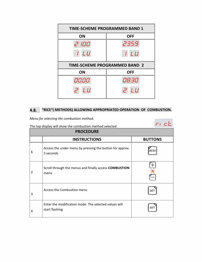
TIME‐SCHEME PROGRAMMED BAND 1
ON OFF
TIME‐SCHEME PROGRAMMED BAND 2
ON OFF
4.8. “RICE”( METHODS) ALLOWING APPROPRIATED OPERATION OF COMBUSTION.
Menu for selecting the combustion method.
The top display will show the combustion method selected
PROCEDURE
INSTRUCTIONS BUTTONS
1 Access the under menu by pressing the button for approx. 3 seconds
2 Scroll through the menus and finally access COMBUSTION menu
3 Access the Combustion menu
4
Enter the modification mode. The selected values will start flashing

5 Change the parameter value
6 Save the settings
7 Exit the menu
NOTE : The programme offers a selection of 4 rice , please select the most suitable according to the working conditions . Rice n. 4 will allow the max. air inlet to the combustion chamber.
4.9. PROGRAMMING THE CLOCK MENU
Allows the time‐scheme value and that of the current date
The top display shows the hour and the minutes
The bottom display the days of the week
PROCEDURE FOR PROGRAMMING THE CLOCK
INSTRUZIONI BUTTONS
1 Access the Menu mode and press the button for 3 seconds
2 Scroll through the menus and finally access CLOCK menu
3 Access the CLOCK menu
4 Enter the modification mode ( the selected values will start flashing)
5 Scroll through the menus until reaching the value to be changed ( the value will start flashing)

6 Change the parameter value
8 Save all modified values
9 Exit the clock menu
NOTE : It is important that this setting is achieved in a correct and appropriate manner. The automatic lighting / extinguishing of the heater will depend from this setting.
4.10 SCREW LOADING
This allows to manually fill the screw during fuel loading
Manual screw loading
Instructions buttons Make sure that the heater is OFF
1 Access the MENU mode by pressing the button for 3 seconds
2
Scroll through the menus and finally access LOAD menu
3
Access the LOAD menu
4
Press SET to action the auger motor. The display will start flashing and it will show the value ‘0001’ . It could be required to repeat the process several times.
5 Press ESC to deactivate the screw
6
Press ESC to exit the menu

NOTE : When the screw is manually activated , the fume fan is also activated and the pressure switch is closed ( safety AT1 with contact normally open) this in order to feed the screw.
NOTE : The heater MUST be switched –off.
4.11. MENU DISPLAYED
The menus display allow you to check the status of the main values shown on the display SY215Evo in order to check the operations .The top display shows the sizes of the values selected.
Pressing the SET button it is possible to scroll through the different size values.
N° CODE DESCRIPTION
1
This is read only when the heater has an encoder . The readout will show the rotation speed of the smoke extraction fan rpm
2
Fume temperature ( °C)
3
Ambient temperature ( °C)
4
Reserved to software installed on the heater
NOTA: According to the heater model , not all codes could be available . The last code is reserved for the software. The version is indicated on the top display along with type.
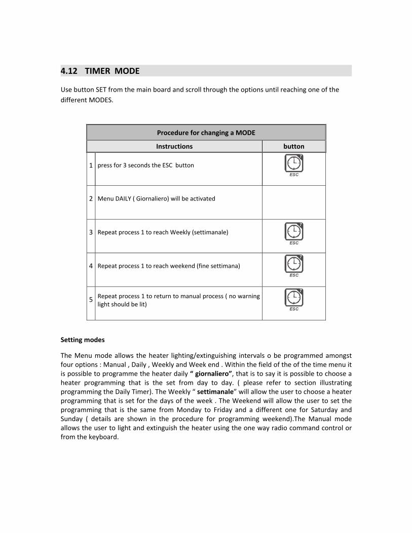
4.12 TIMER MODE
Use button SET from the main board and scroll through the options until reaching one of the different MODES.
Procedure for changing a MODE
Instructions button
1 press for 3 seconds the ESC button
2 Menu DAILY ( Giornaliero) will be activated
3 Repeat process 1 to reach Weekly (settimanale)
4 Repeat process 1 to reach weekend (fine settimana)
5 Repeat process 1 to return to manual process ( no warning light should be lit)
Setting modes
The Menu mode allows the heater lighting/extinguishing intervals o be programmed amongst four options : Manual , Daily , Weekly and Week end . Within the field of the of the time menu it is possible to programme the heater daily “ giornaliero”, that is to say it is possible to choose a heater programming that is the set from day to day. ( please refer to section illustrating programming the Daily Timer). The Weekly “ settimanale” will allow the user to choose a heater programming that is set for the days of the week . The Weekend will allow the user to set the programming that is the same from Monday to Friday and a different one for Saturday and Sunday ( details are shown in the procedure for programming weekend).The Manual mode allows the user to light and extinguish the heater using the one way radio command control or from the keyboard.

One‐way radio control
Figure 5.1. : One-way Radio Control
Through this radio control , that has a range of action of 10 meters , it is possible to regulate some heater operating parameters .
Hereafter some functions performed by the SYTX control :
− ON / OFF
− Operating power increase/decrease
Instructions on the interferences:
The capacity of action of the device can meaningfully be reduced in case of noisy environment: other apparatuses such as wireless earphones or other electronic devices which could influence the performances of the system. After having checked that the apparatuses are within the limits of the heater, extinguish them or use them only if required avoiding useless pollution of the electromagnetic effects.
Whereas one or more radio controls are found in the proximities of the heater (and vice‐versa) then it is necessary to associate the radio‐control with the specific product (you see procedure of change and learning the codes of the radio‐control ).

5.1 ABOUT THE RADIO‐CONTROL CODES
The radio‐control signal is detected by a code on the control board, and it is possible to change the code following, hereafter we are supplying the procedure.
The correct transmission between radio‐control and control board, the transmission code must be the same on both the devices. The default code is planned on 0, and if the user needs to change the code, below is a description of the methods of changing the code:
On the radio control:
− Open the battery holding unit ‐ moving the cover toward right ; − Change the configuration of the dip‐switches; − Close the radio‐control again.
On the board:
− Cut‐off the power feed to the board; − Activate power feed to the board , pressing the radio‐control at the same time; − Wait (for about 5 second) for the audible signal sound coming from the board, this will
confirm acknowledgment of the new code.

Registered address:Vokèra Ltd
Borderlake HouseUnit 7 Riverside Industrial Estate
London ColneyHerts AL2 1HG
www.vokera.co.ukwww.vokera.ie
Sales, General EnquiresT 0844 391 099
F 0844 391 0998
Vokèra IrelandWest Court, Callan
Co KilkennyT 056 7755057F 056 7755060
Vokèra Limited reserve the right to changespecification without prior notice
Consumers statutory rights are not affected.
A Riello Group Company.Company Reg No: 1047779