mzr-cd2.2 engine common rail system (crs) service … · 2019-03-05 · (1) crankshaft position...
TRANSCRIPT
COMMON RAIL SYSTEM (CRS) SERVICE MANUAL: Operation
MZR-CD2.2 Engine
Applicable Vehicle :Manufacturer Vehicle Name
MAZDAMAZDA3MAZDA6CX-7
Issued : February 2009Revised : October 2009
00400689EA
© 2009 DENSO CORPORATIONAll rights reserved. This material may not be reproduced or copied, in whole or in part, without the written permission of DENSO Corporation.
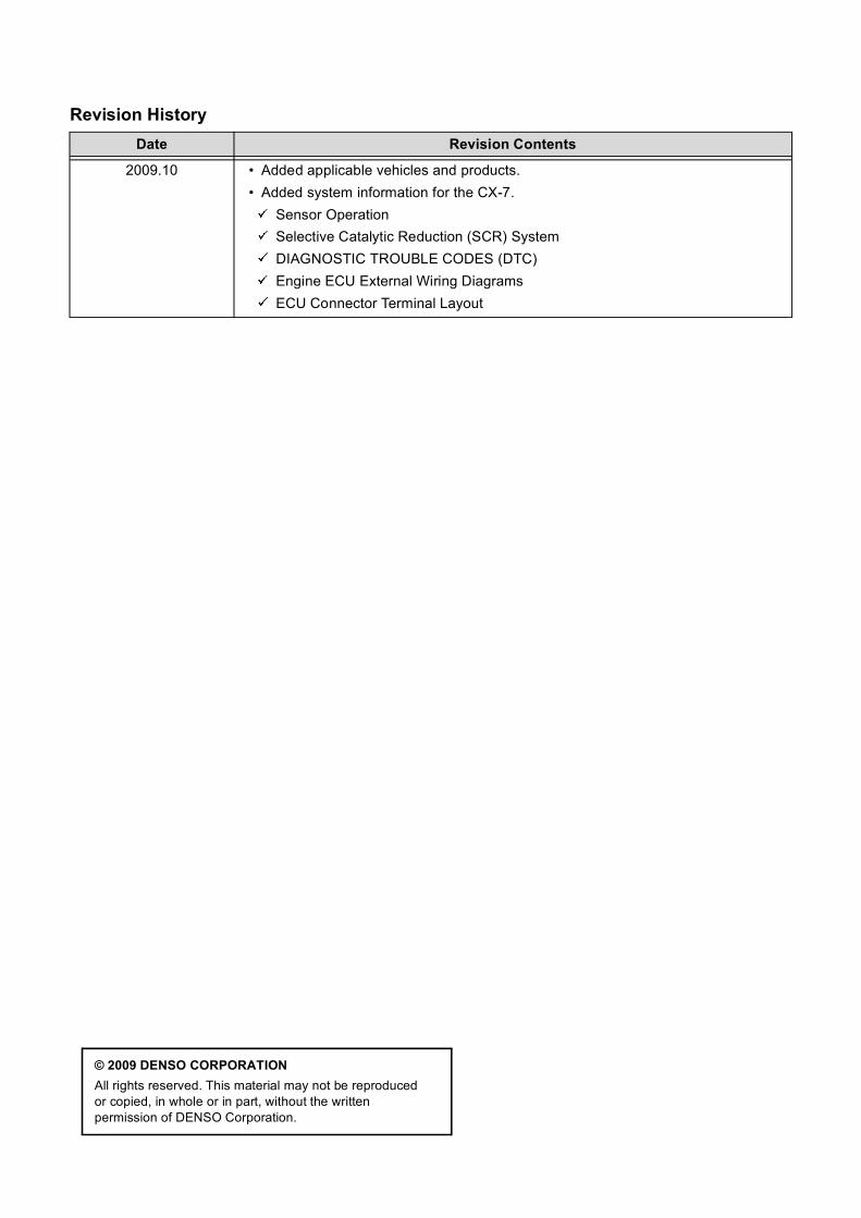
Revision HistoryDate Revision Contents
2009.10 • Added applicable vehicles and products.• Added system information for the CX-7.
Sensor OperationSelective Catalytic Reduction (SCR) SystemDIAGNOSTIC TROUBLE CODES (DTC)Engine ECU External Wiring DiagramsECU Connector Terminal Layout
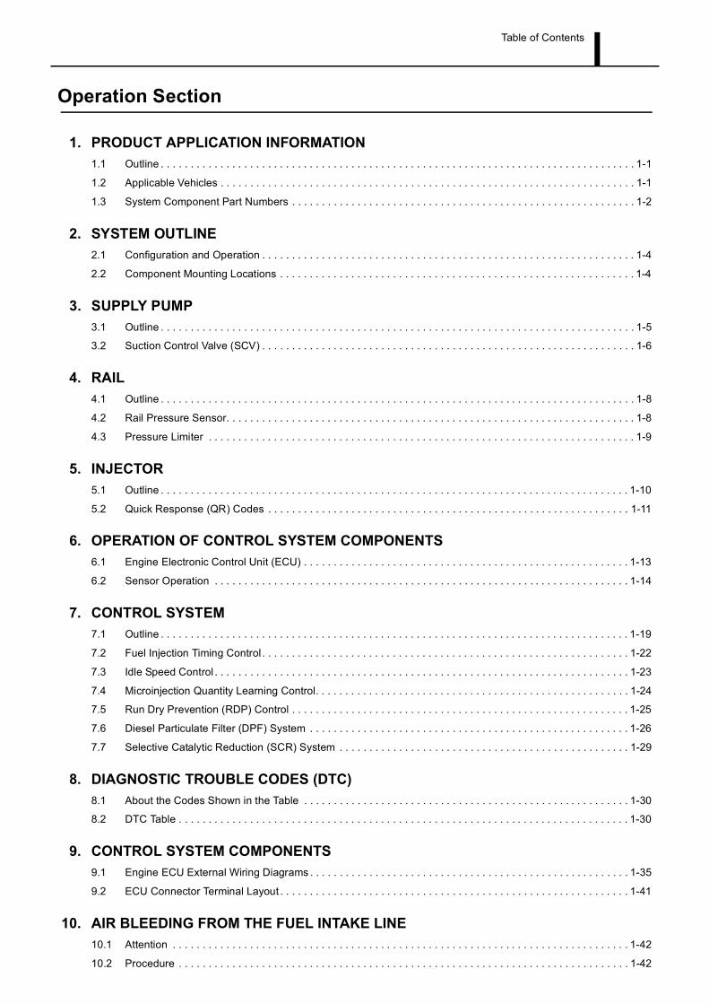
Table of Contents
Operation Section
1. PRODUCT APPLICATION INFORMATION1.1 Outline . . . . . . . . . . . . . . . . . . . . . . . . . . . . . . . . . . . . . . . . . . . . . . . . . . . . . . . . . . . . . . . . . . . . . . . . . . . . . . . . 1-1
1.2 Applicable Vehicles . . . . . . . . . . . . . . . . . . . . . . . . . . . . . . . . . . . . . . . . . . . . . . . . . . . . . . . . . . . . . . . . . . . . . . 1-1
1.3 System Component Part Numbers . . . . . . . . . . . . . . . . . . . . . . . . . . . . . . . . . . . . . . . . . . . . . . . . . . . . . . . . . . 1-2
2. SYSTEM OUTLINE2.1 Configuration and Operation . . . . . . . . . . . . . . . . . . . . . . . . . . . . . . . . . . . . . . . . . . . . . . . . . . . . . . . . . . . . . . . 1-4
2.2 Component Mounting Locations . . . . . . . . . . . . . . . . . . . . . . . . . . . . . . . . . . . . . . . . . . . . . . . . . . . . . . . . . . . . 1-4
3. SUPPLY PUMP3.1 Outline . . . . . . . . . . . . . . . . . . . . . . . . . . . . . . . . . . . . . . . . . . . . . . . . . . . . . . . . . . . . . . . . . . . . . . . . . . . . . . . . 1-5
3.2 Suction Control Valve (SCV) . . . . . . . . . . . . . . . . . . . . . . . . . . . . . . . . . . . . . . . . . . . . . . . . . . . . . . . . . . . . . . . 1-6
4. RAIL4.1 Outline . . . . . . . . . . . . . . . . . . . . . . . . . . . . . . . . . . . . . . . . . . . . . . . . . . . . . . . . . . . . . . . . . . . . . . . . . . . . . . . . 1-8
4.2 Rail Pressure Sensor. . . . . . . . . . . . . . . . . . . . . . . . . . . . . . . . . . . . . . . . . . . . . . . . . . . . . . . . . . . . . . . . . . . . . 1-8
4.3 Pressure Limiter . . . . . . . . . . . . . . . . . . . . . . . . . . . . . . . . . . . . . . . . . . . . . . . . . . . . . . . . . . . . . . . . . . . . . . . . 1-9
5. INJECTOR5.1 Outline . . . . . . . . . . . . . . . . . . . . . . . . . . . . . . . . . . . . . . . . . . . . . . . . . . . . . . . . . . . . . . . . . . . . . . . . . . . . . . . 1-10
5.2 Quick Response (QR) Codes . . . . . . . . . . . . . . . . . . . . . . . . . . . . . . . . . . . . . . . . . . . . . . . . . . . . . . . . . . . . . 1-11
6. OPERATION OF CONTROL SYSTEM COMPONENTS6.1 Engine Electronic Control Unit (ECU) . . . . . . . . . . . . . . . . . . . . . . . . . . . . . . . . . . . . . . . . . . . . . . . . . . . . . . . 1-13
6.2 Sensor Operation . . . . . . . . . . . . . . . . . . . . . . . . . . . . . . . . . . . . . . . . . . . . . . . . . . . . . . . . . . . . . . . . . . . . . . 1-14
7. CONTROL SYSTEM7.1 Outline . . . . . . . . . . . . . . . . . . . . . . . . . . . . . . . . . . . . . . . . . . . . . . . . . . . . . . . . . . . . . . . . . . . . . . . . . . . . . . . 1-19
7.2 Fuel Injection Timing Control . . . . . . . . . . . . . . . . . . . . . . . . . . . . . . . . . . . . . . . . . . . . . . . . . . . . . . . . . . . . . . 1-22
7.3 Idle Speed Control . . . . . . . . . . . . . . . . . . . . . . . . . . . . . . . . . . . . . . . . . . . . . . . . . . . . . . . . . . . . . . . . . . . . . . 1-23
7.4 Microinjection Quantity Learning Control. . . . . . . . . . . . . . . . . . . . . . . . . . . . . . . . . . . . . . . . . . . . . . . . . . . . . 1-24
7.5 Run Dry Prevention (RDP) Control . . . . . . . . . . . . . . . . . . . . . . . . . . . . . . . . . . . . . . . . . . . . . . . . . . . . . . . . . 1-25
7.6 Diesel Particulate Filter (DPF) System . . . . . . . . . . . . . . . . . . . . . . . . . . . . . . . . . . . . . . . . . . . . . . . . . . . . . . 1-26
7.7 Selective Catalytic Reduction (SCR) System . . . . . . . . . . . . . . . . . . . . . . . . . . . . . . . . . . . . . . . . . . . . . . . . . 1-29
8. DIAGNOSTIC TROUBLE CODES (DTC)8.1 About the Codes Shown in the Table . . . . . . . . . . . . . . . . . . . . . . . . . . . . . . . . . . . . . . . . . . . . . . . . . . . . . . . 1-30
8.2 DTC Table . . . . . . . . . . . . . . . . . . . . . . . . . . . . . . . . . . . . . . . . . . . . . . . . . . . . . . . . . . . . . . . . . . . . . . . . . . . . 1-30
9. CONTROL SYSTEM COMPONENTS9.1 Engine ECU External Wiring Diagrams . . . . . . . . . . . . . . . . . . . . . . . . . . . . . . . . . . . . . . . . . . . . . . . . . . . . . . 1-35
9.2 ECU Connector Terminal Layout . . . . . . . . . . . . . . . . . . . . . . . . . . . . . . . . . . . . . . . . . . . . . . . . . . . . . . . . . . . 1-41
10. AIR BLEEDING FROM THE FUEL INTAKE LINE10.1 Attention . . . . . . . . . . . . . . . . . . . . . . . . . . . . . . . . . . . . . . . . . . . . . . . . . . . . . . . . . . . . . . . . . . . . . . . . . . . . . 1-42
10.2 Procedure . . . . . . . . . . . . . . . . . . . . . . . . . . . . . . . . . . . . . . . . . . . . . . . . . . . . . . . . . . . . . . . . . . . . . . . . . . . . 1-42

Operation Section1–1
1. PRODUCT APPLICATION INFORMATION
1.1 Outline
The MAZDA3 has undergone a full model change. In addition, the engine used in the MAZDA6 has been
changed. As a result, the MZR-CD 2.2 engine is now used in both the MAZDA3, and MAZDA6. Further, the
Common Rail System (CRS) has been modified due to the aforementioned engine change. For CRS basics,
refer to the "COMMON RAIL SYSTEM SERVICE MANUAL -OPERATION (Doc ID:00400534EA)".
Modifications made due to the model change are listed below.
• Maximum injection pressure increased to 200 MPa.
• Run Dry Prevention (RDP) control added.
• Microinjection quantity learning control added.
• Diesel Particulate Filter (DPF) system added.
As a result of a model change to the MAZDA CX-7 beginning from October 2009, the CX-7 now also uses
the MZR-CD 2.2 engine. The MZD-CD 2.2 engine in the CX-7 is equipped with the Selective Catalytic
Reduction (SCR) system. The SCR system dramatically reduces the quantity of NOx exhaust, and achieves
superior environmental protection functionality suited to the stringent European emission standards
stipulated in the "EURO 5" regulations.
In comparison to the CRS used in the MAZDA3 and MAZDA6, the CRS for the CX-7 includes the following
additional system. An explanation of this system has been added to this manual.
• Refer to [Selective Catalytic Reduction (SCR) System] on P1-29
Unless otherwise noted, the explanations for each control and part applies to all three vehicles mentioned
in this manual.
1.2 Applicable Vehicles
Model Name Engine Engine Displacement Destination Line Off Period
MAZDA3
MZR-CD 2.2 2.2 L Europe
January 2009
MAZDA6 May 2008
CX-7 October 2009
Operation Section1–2
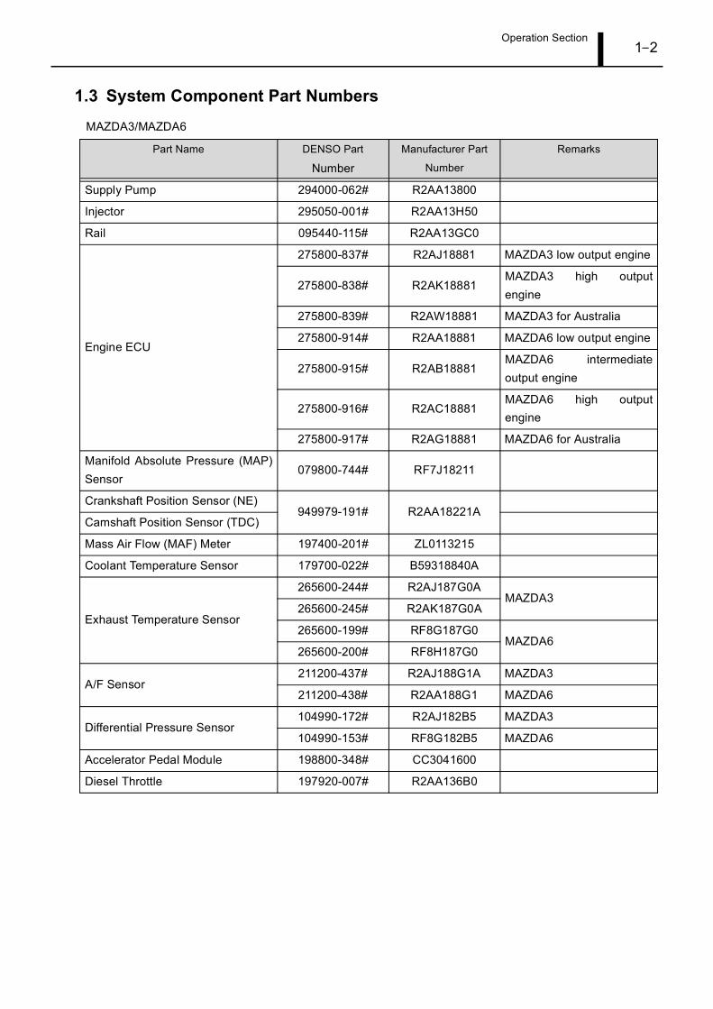
1.3 System Component Part Numbers
MAZDA3/MAZDA6
Part Name DENSO Part
NumberManufacturer Part
Number
Remarks
Supply Pump 294000-062# R2AA13800
Injector 295050-001# R2AA13H50
Rail 095440-115# R2AA13GC0
Engine ECU
275800-837# R2AJ18881 MAZDA3 low output engine
275800-838# R2AK18881MAZDA3 high outputengine
275800-839# R2AW18881 MAZDA3 for Australia
275800-914# R2AA18881 MAZDA6 low output engine
275800-915# R2AB18881MAZDA6 intermediateoutput engine
275800-916# R2AC18881MAZDA6 high outputengine
275800-917# R2AG18881 MAZDA6 for Australia
Manifold Absolute Pressure (MAP)Sensor
079800-744# RF7J18211
Crankshaft Position Sensor (NE)949979-191# R2AA18221A
Camshaft Position Sensor (TDC)
Mass Air Flow (MAF) Meter 197400-201# ZL0113215
Coolant Temperature Sensor 179700-022# B59318840A
Exhaust Temperature Sensor
265600-244# R2AJ187G0AMAZDA3
265600-245# R2AK187G0A
265600-199# RF8G187G0MAZDA6
265600-200# RF8H187G0
A/F Sensor211200-437# R2AJ188G1A MAZDA3
211200-438# R2AA188G1 MAZDA6
Differential Pressure Sensor104990-172# R2AJ182B5 MAZDA3
104990-153# RF8G182B5 MAZDA6
Accelerator Pedal Module 198800-348# CC3041600
Diesel Throttle 197920-007# R2AA136B0
Operation Section1–3
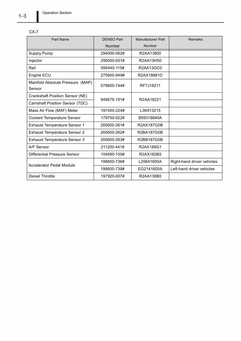
CX-7
Part Name DENSO Part
Number
Manufacturer Part
Number
Remarks
Supply Pump 294000-062# R2AA13800
Injector 295050-001# R2AA13H50
Rail 095440-115# R2AA13GC0
Engine ECU 275800-949# R2AX18881D
Manifold Absolute Pressure (MAP)Sensor
079800-744# RF7J18211
Crankshaft Position Sensor (NE)949979-191# R2AA18221
Camshaft Position Sensor (TDC)
Mass Air Flow (MAF) Meter 197400-224# L3K913215
Coolant Temperature Sensor 179700-022# B59318840A
Exhaust Temperature Sensor 1 265600-261# R2AX187G0B
Exhaust Temperature Sensor 2 265600-262# R2BA187G0B
Exhaust Temperature Sensor 3 265600-263# R2BB187G0B
A/F Sensor 211200-441# R2AX188G1
Differential Pressure Sensor 104990-155# R2AX182B5
Accelerator Pedal Module198800-736# L20641600A Right-hand driver vehicles
198800-739# EG2141600A Left-hand driver vehicles
Diesel Throttle 197920-007# R2AA136B0
Operation Section1–4
2. SYSTEM OUTLINE
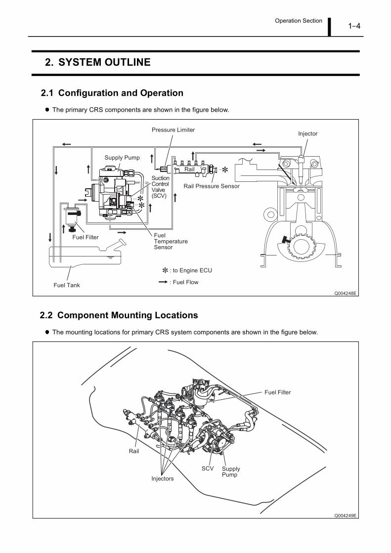
2.1 Configuration and Operation
The primary CRS components are shown in the figure below.
2.2 Component Mounting Locations
The mounting locations for primary CRS system components are shown in the figure below.
Operation Section1–5
3. SUPPLY PUMP
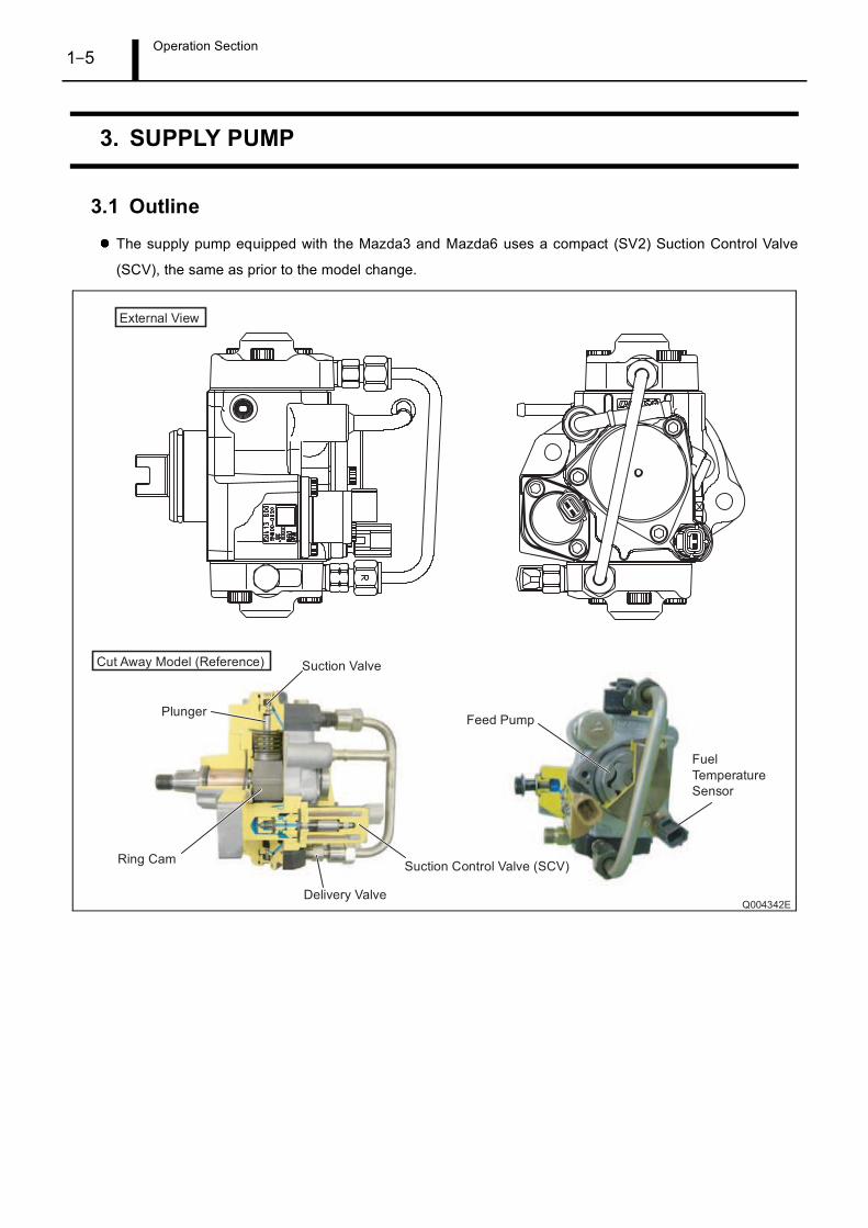
3.1 Outline
The supply pump equipped with the Mazda3 and Mazda6 uses a compact (SV2) Suction Control Valve
(SCV), the same as prior to the model change.
Operation Section1–6
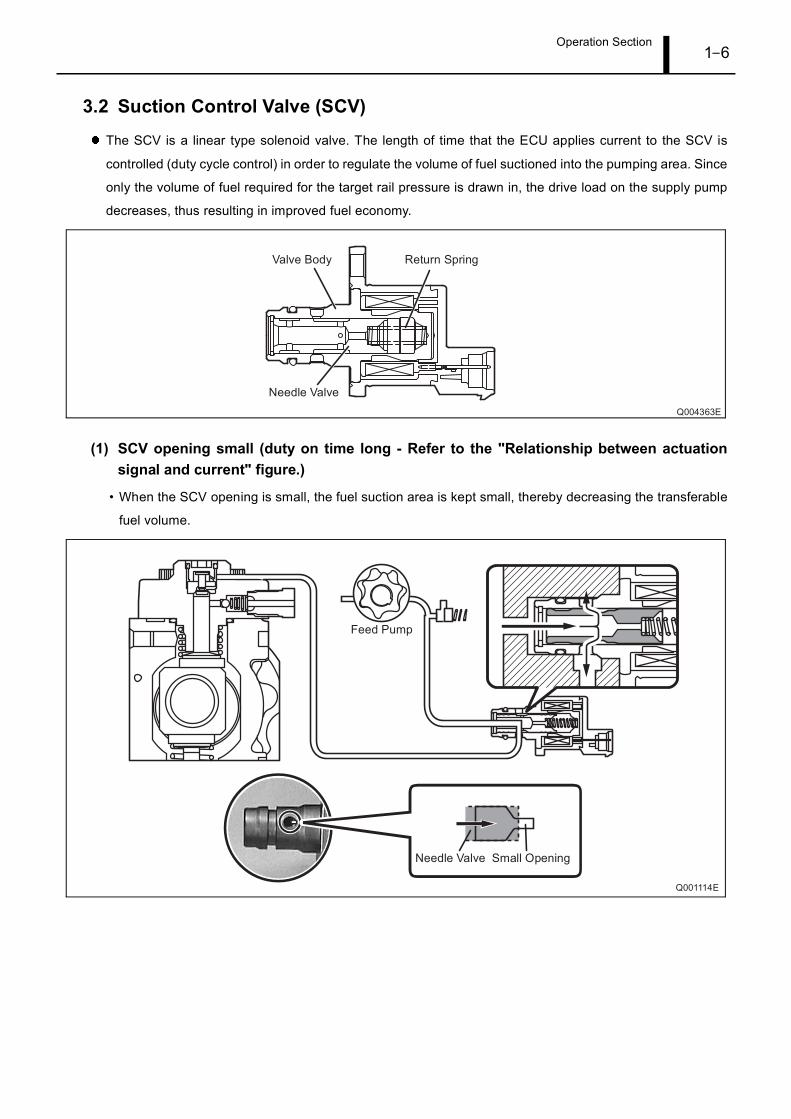
3.2 Suction Control Valve (SCV)
The SCV is a linear type solenoid valve. The length of time that the ECU applies current to the SCV is
controlled (duty cycle control) in order to regulate the volume of fuel suctioned into the pumping area. Since
only the volume of fuel required for the target rail pressure is drawn in, the drive load on the supply pump
decreases, thus resulting in improved fuel economy.
(1) SCV opening small (duty on time long - Refer to the "Relationship between actuationsignal and current" figure.)
• When the SCV opening is small, the fuel suction area is kept small, thereby decreasing the transferable
fuel volume.
Operation Section1–7
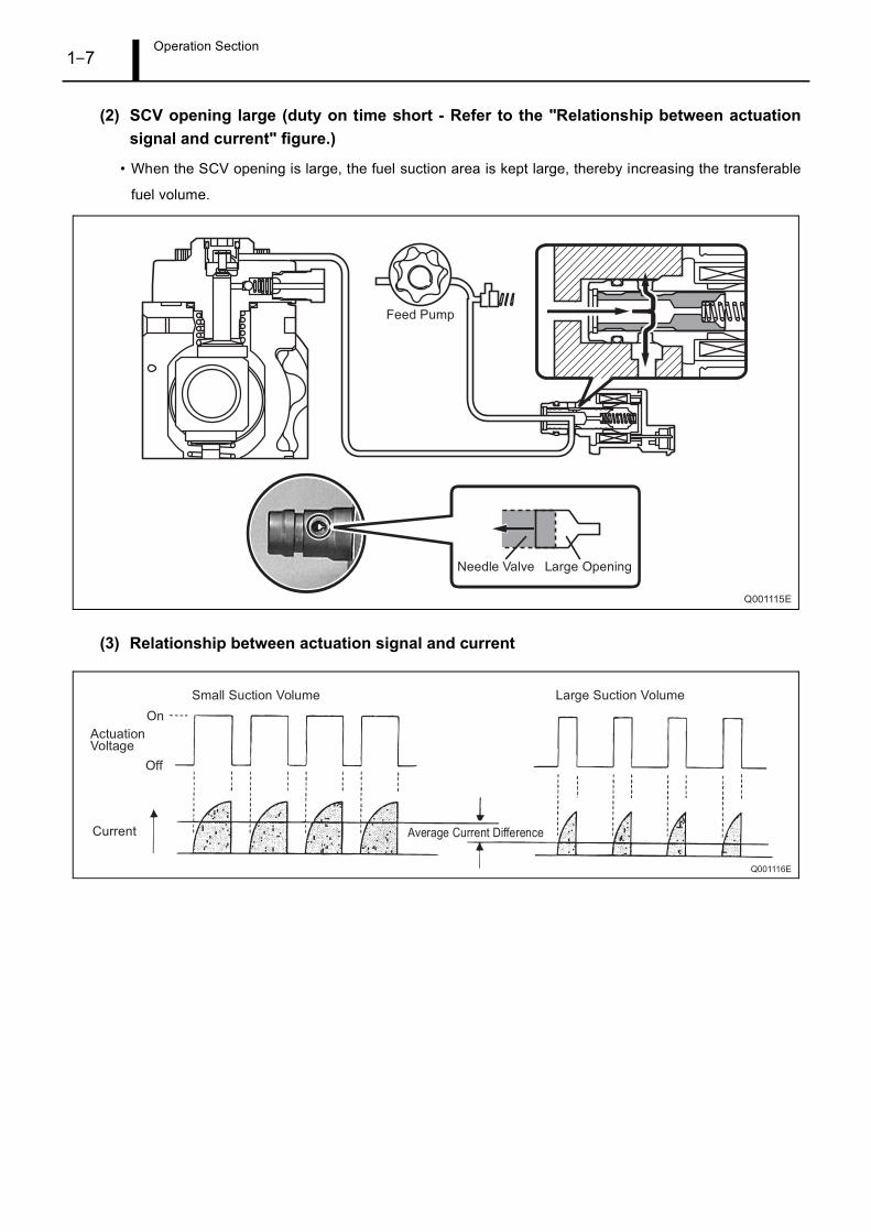
(2) SCV opening large (duty on time short - Refer to the "Relationship between actuationsignal and current" figure.)
• When the SCV opening is large, the fuel suction area is kept large, thereby increasing the transferable
fuel volume.
(3) Relationship between actuation signal and current
Operation Section1–8
4. RAIL
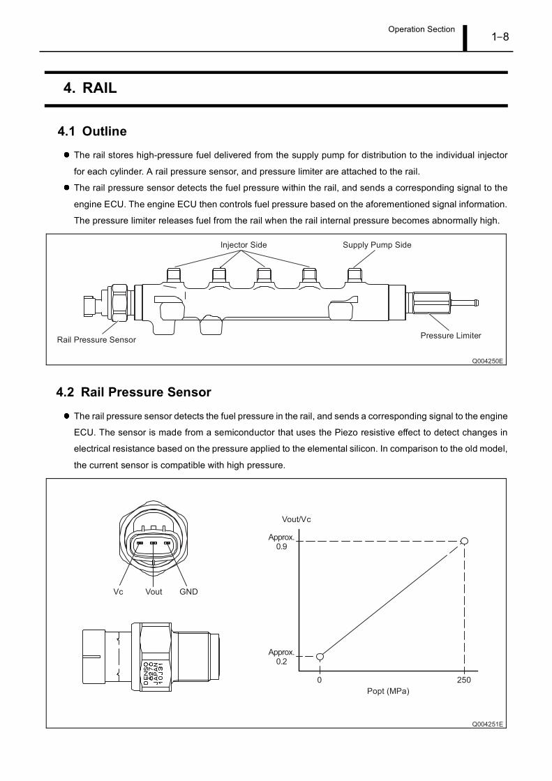
4.1 Outline
The rail stores high-pressure fuel delivered from the supply pump for distribution to the individual injector
for each cylinder. A rail pressure sensor, and pressure limiter are attached to the rail.
The rail pressure sensor detects the fuel pressure within the rail, and sends a corresponding signal to the
engine ECU. The engine ECU then controls fuel pressure based on the aforementioned signal information.
The pressure limiter releases fuel from the rail when the rail internal pressure becomes abnormally high.
4.2 Rail Pressure Sensor
The rail pressure sensor detects the fuel pressure in the rail, and sends a corresponding signal to the engine
ECU. The sensor is made from a semiconductor that uses the Piezo resistive effect to detect changes in
electrical resistance based on the pressure applied to the elemental silicon. In comparison to the old model,
the current sensor is compatible with high pressure.
Operation Section1–9
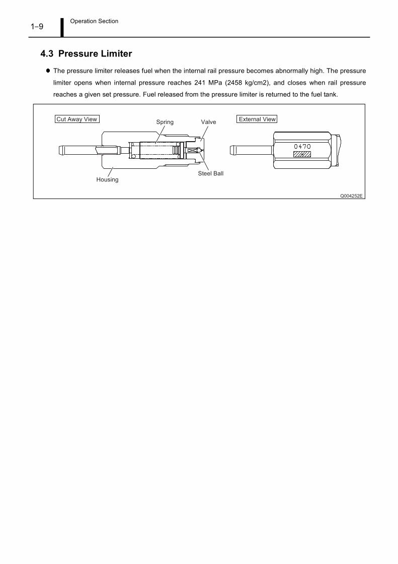
4.3 Pressure Limiter
The pressure limiter releases fuel when the internal rail pressure becomes abnormally high. The pressure
limiter opens when internal pressure reaches 241 MPa (2458 kg/cm2), and closes when rail pressure
reaches a given set pressure. Fuel released from the pressure limiter is returned to the fuel tank.
Operation Section1–10
5. INJECTOR
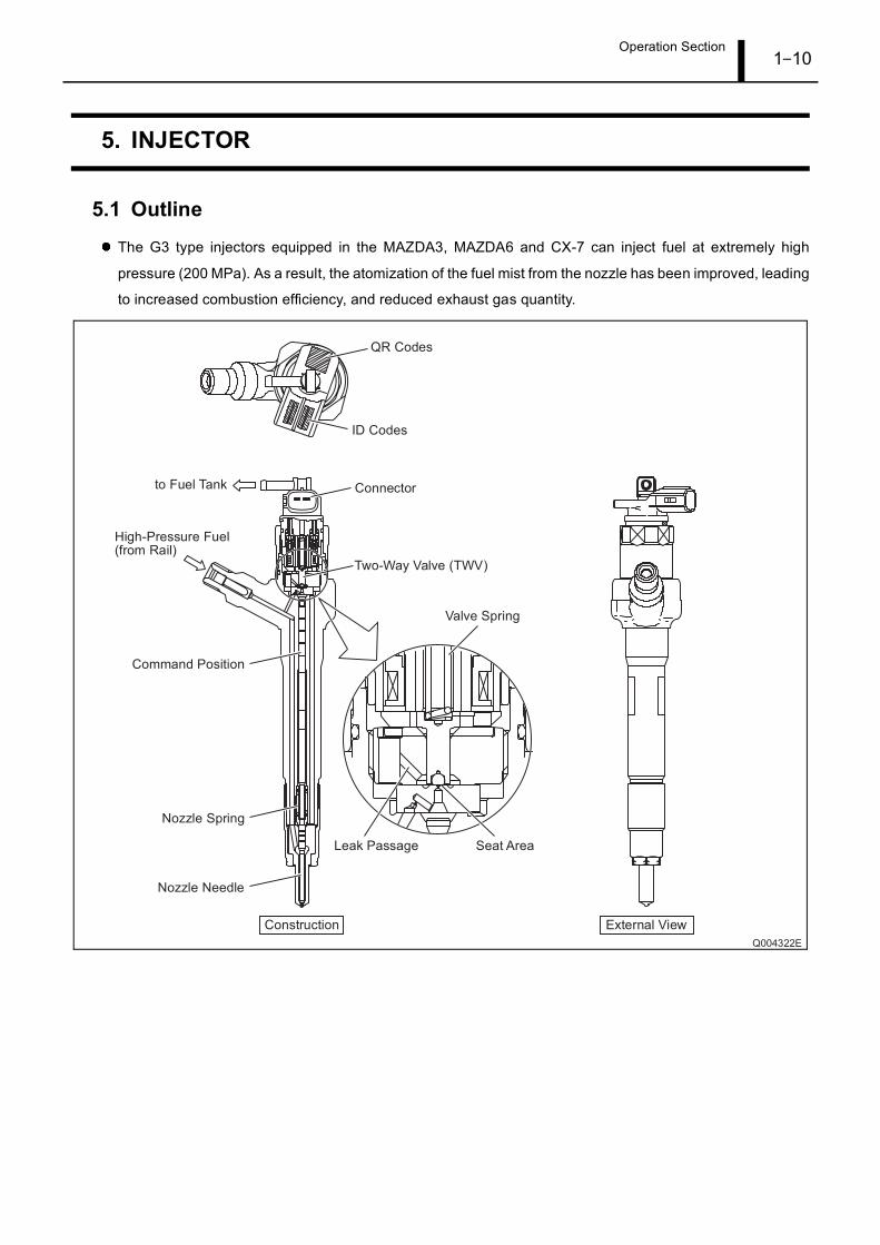
5.1 Outline
The G3 type injectors equipped in the MAZDA3, MAZDA6 and CX-7 can inject fuel at extremely high
pressure (200 MPa). As a result, the atomization of the fuel mist from the nozzle has been improved, leading
to increased combustion efficiency, and reduced exhaust gas quantity.
Operation Section1–11
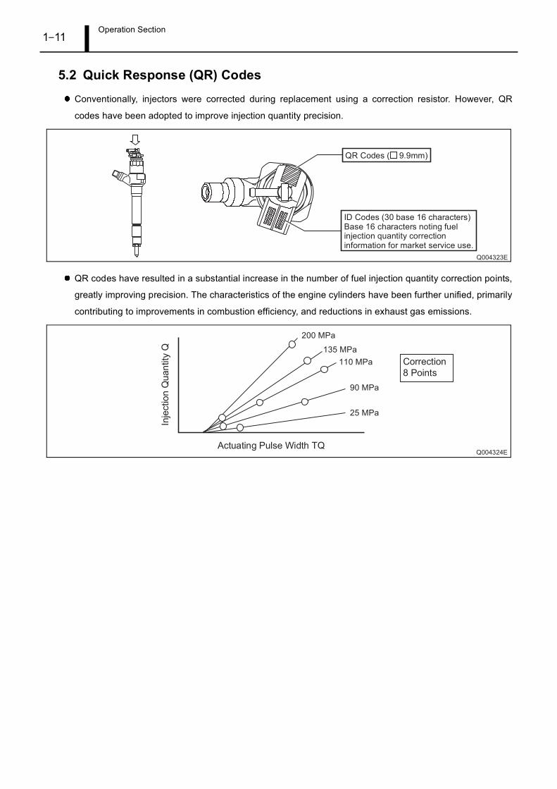
5.2 Quick Response (QR) Codes
Conventionally, injectors were corrected during replacement using a correction resistor. However, QR
codes have been adopted to improve injection quantity precision.
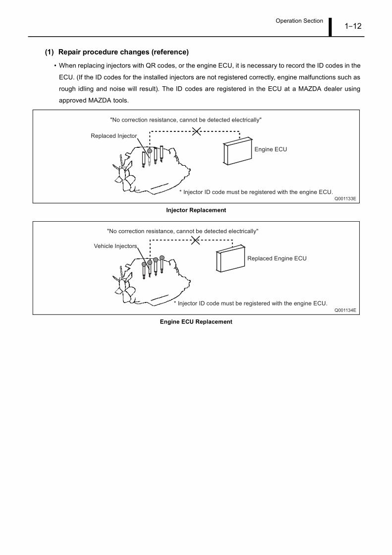
QR codes have resulted in a substantial increase in the number of fuel injection quantity correction points,
greatly improving precision. The characteristics of the engine cylinders have been further unified, primarily
contributing to improvements in combustion efficiency, and reductions in exhaust gas emissions.
Operation Section1–12
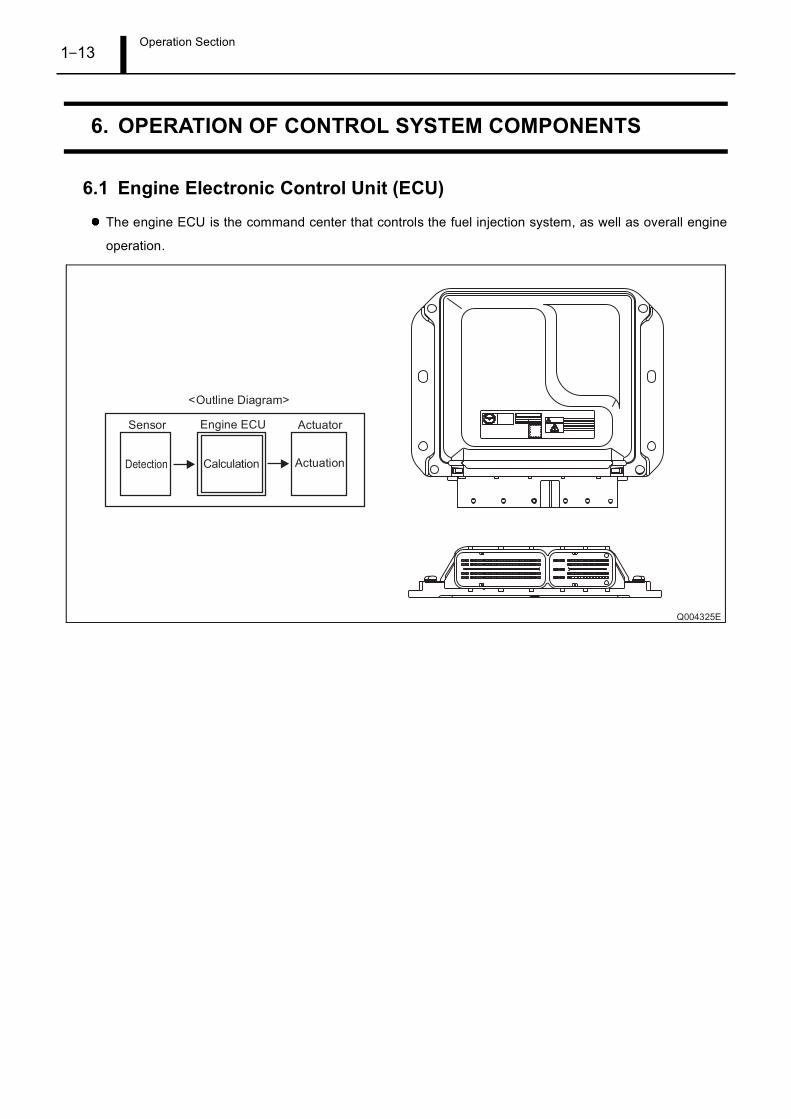
(1) Repair procedure changes (reference)
• When replacing injectors with QR codes, or the engine ECU, it is necessary to record the ID codes in the
ECU. (If the ID codes for the installed injectors are not registered correctly, engine malfunctions such as
rough idling and noise will result). The ID codes are registered in the ECU at a MAZDA dealer using
approved MAZDA tools.
Injector Replacement
Engine ECU Replacement
Operation Section1–13
6. OPERATION OF CONTROL SYSTEM COMPONENTS
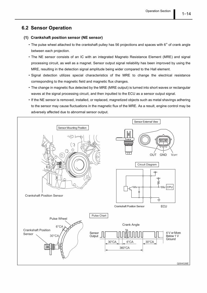
6.1 Engine Electronic Control Unit (ECU)
The engine ECU is the command center that controls the fuel injection system, as well as overall engine
operation.
Operation Section1–14
6.2 Sensor Operation
(1) Crankshaft position sensor (NE sensor)
• The pulse wheel attached to the crankshaft pulley has 56 projections and spaces with 6° of crank angle
between each projection.
• The NE sensor consists of an IC with an integrated Magneto Resistance Element (MRE) and signal
processing circuit, as well as a magnet. Sensor output signal reliability has been improved by using the
MRE, resulting in the detection signal amplitude being wider compared to the Hall element.
• Signal detection utilizes special characteristics of the MRE to change the electrical resistance
corresponding to the magnetic field and magnetic flux changes.
• The change in magnetic flux detected by the MRE (MRE output) is turned into short waves or rectangular
waves at the signal processing circuit, and then inputted to the ECU as a sensor output signal.
• If the NE sensor is removed, installed, or replaced, magnetized objects such as metal shavings adhering
to the sensor may cause fluctuations in the magnetic flux of the MRE. As a result, engine control may be
adversely affected due to abnormal sensor output.
Operation Section1–15
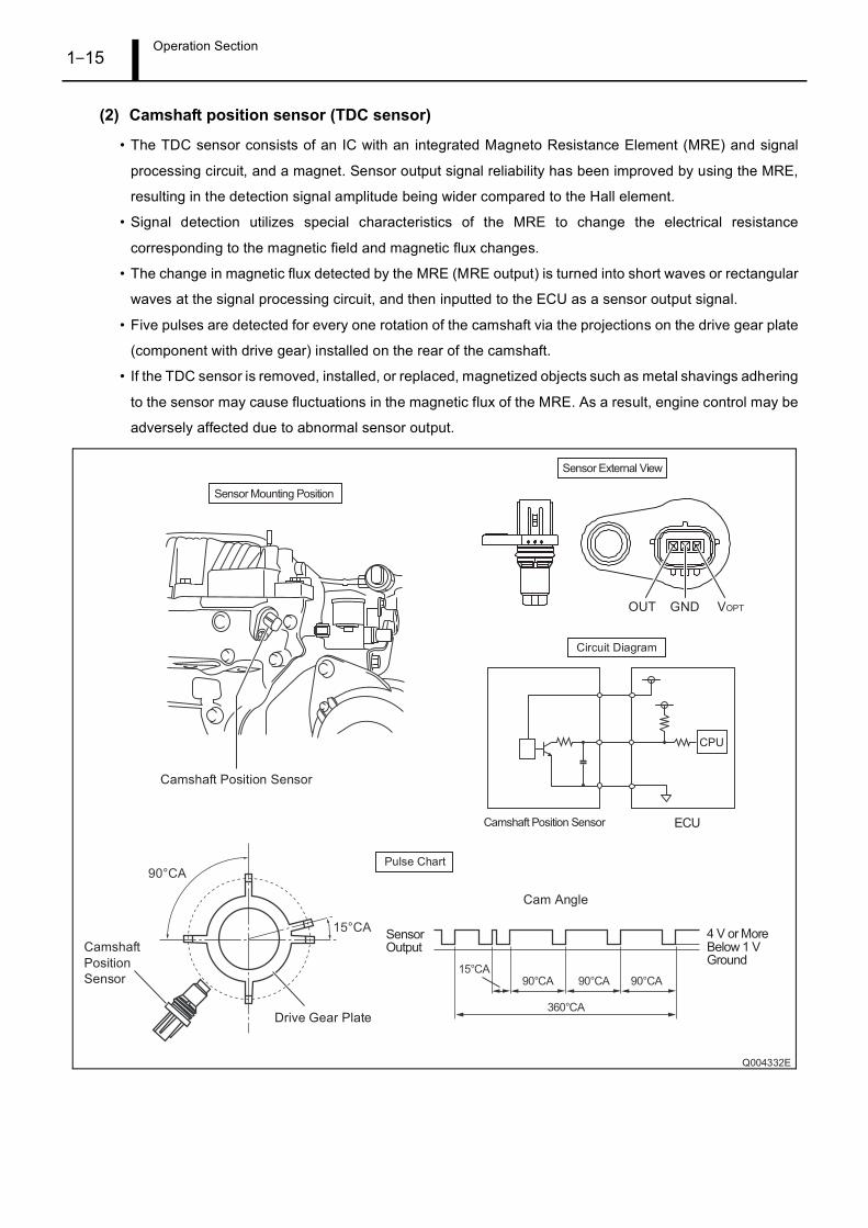
(2) Camshaft position sensor (TDC sensor)
• The TDC sensor consists of an IC with an integrated Magneto Resistance Element (MRE) and signal
processing circuit, and a magnet. Sensor output signal reliability has been improved by using the MRE,
resulting in the detection signal amplitude being wider compared to the Hall element.
• Signal detection utilizes special characteristics of the MRE to change the electrical resistance
corresponding to the magnetic field and magnetic flux changes.
• The change in magnetic flux detected by the MRE (MRE output) is turned into short waves or rectangular
waves at the signal processing circuit, and then inputted to the ECU as a sensor output signal.
• Five pulses are detected for every one rotation of the camshaft via the projections on the drive gear plate
(component with drive gear) installed on the rear of the camshaft.
• If the TDC sensor is removed, installed, or replaced, magnetized objects such as metal shavings adhering
to the sensor may cause fluctuations in the magnetic flux of the MRE. As a result, engine control may be
adversely affected due to abnormal sensor output.
Operation Section1–16
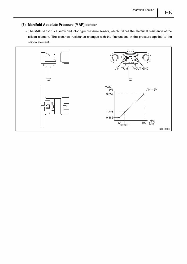
(3) Manifold Absolute Pressure (MAP) sensor
• The MAP sensor is a semiconductor type pressure sensor, which utilizes the electrical resistance of the
silicon element. The electrical resistance changes with the fluctuations in the pressure applied to the
silicon element.
Operation Section1–17
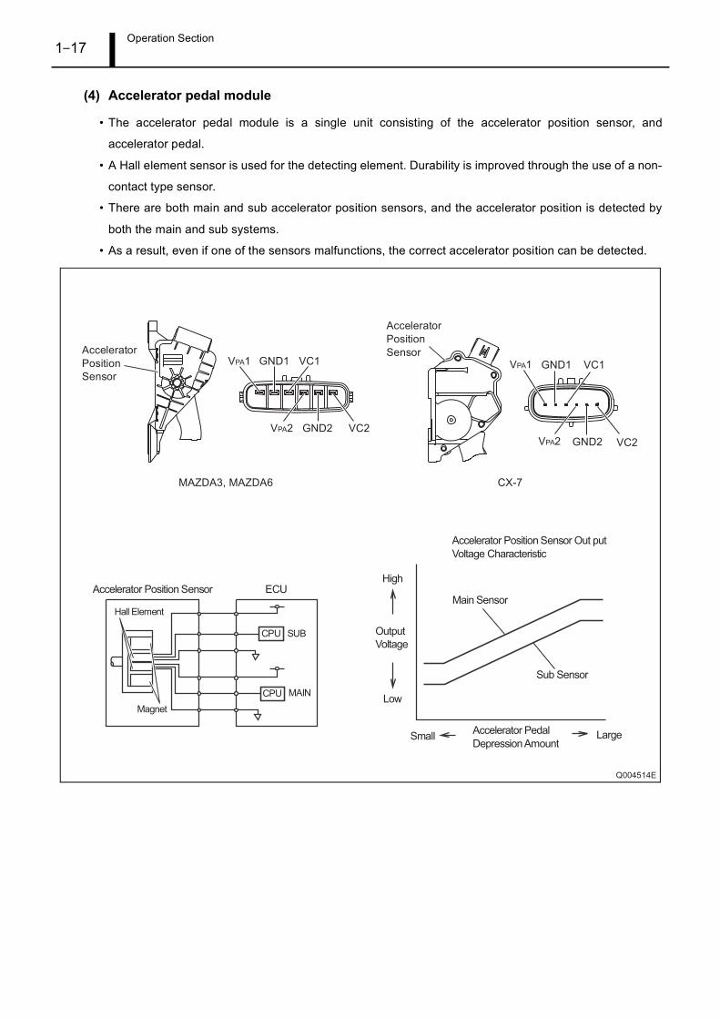
(4) Accelerator pedal module
• The accelerator pedal module is a single unit consisting of the accelerator position sensor, and
accelerator pedal.
• A Hall element sensor is used for the detecting element. Durability is improved through the use of a non-
contact type sensor.
• There are both main and sub accelerator position sensors, and the accelerator position is detected by
both the main and sub systems.
• As a result, even if one of the sensors malfunctions, the correct accelerator position can be detected.
Operation Section1–18
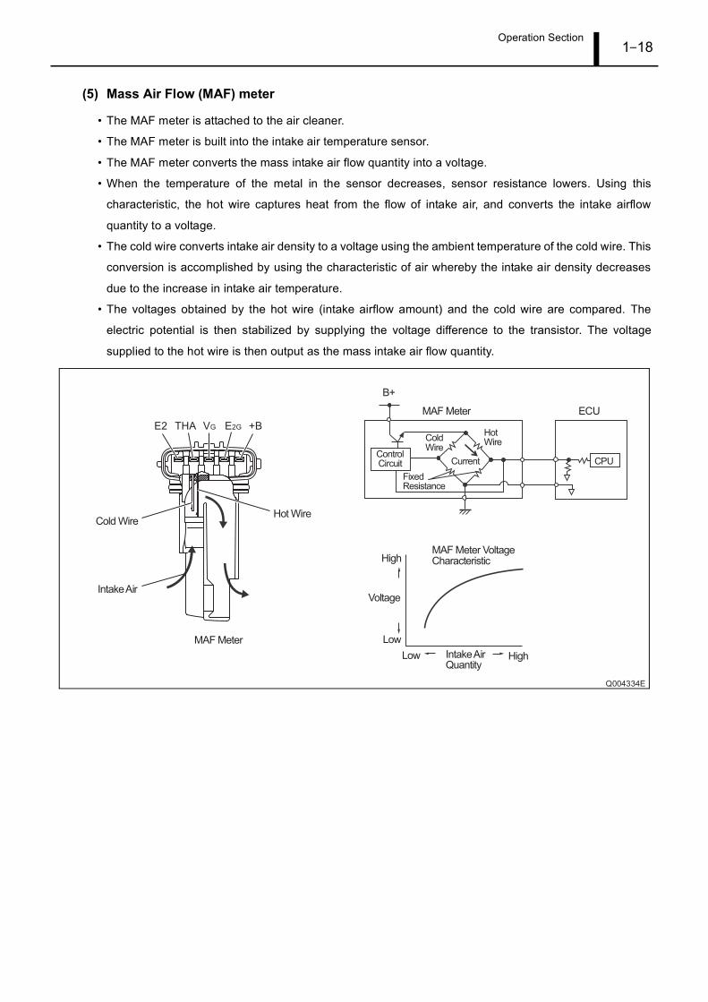
(5) Mass Air Flow (MAF) meter
• The MAF meter is attached to the air cleaner.
• The MAF meter is built into the intake air temperature sensor.
• The MAF meter converts the mass intake air flow quantity into a voltage.
• When the temperature of the metal in the sensor decreases, sensor resistance lowers. Using this
characteristic, the hot wire captures heat from the flow of intake air, and converts the intake airflow
quantity to a voltage.
• The cold wire converts intake air density to a voltage using the ambient temperature of the cold wire. This
conversion is accomplished by using the characteristic of air whereby the intake air density decreases
due to the increase in intake air temperature.
• The voltages obtained by the hot wire (intake airflow amount) and the cold wire are compared. The
electric potential is then stabilized by supplying the voltage difference to the transistor. The voltage
supplied to the hot wire is then output as the mass intake air flow quantity.
Operation Section1–19
7. CONTROL SYSTEM
7.1 Outline
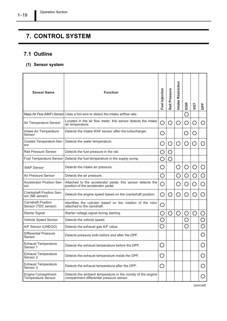
(1) Sensor system
Operation Section1–20
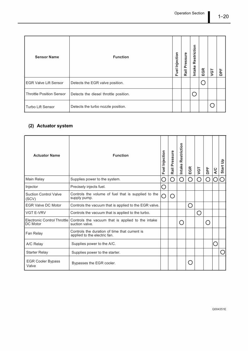
(2) Actuator system
Operation Section1–21
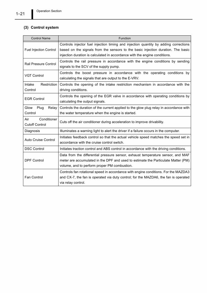
(3) Control system
Control Name Function
Fuel Injection ControlControls injector fuel injection timing and injection quantity by adding correctionsbased on the signals from the sensors to the basic injection duration. The basicinjection duration is calculated in accordance with the engine conditions.
Rail Pressure ControlControls the rail pressure in accordance with the engine conditions by sendingsignals to the SCV of the supply pump.
VGT ControlControls the boost pressure in accordance with the operating conditions bycalculating the signals that are output to the E-VRV.
Intake RestrictionControl
Controls the opening of the intake restriction mechanism in accordance with thedriving conditions.
EGR ControlControls the opening of the EGR valve in accordance with operating conditions bycalculating the output signals.
Glow Plug RelayControl
Controls the duration of the current applied to the glow plug relay in accordance withthe water temperature when the engine is started.
Air ConditionerCutoff Control
Cuts off the air conditioner during acceleration to improve drivability.
Diagnosis Illuminates a warning light to alert the driver if a failure occurs in the computer.
Auto Cruise ControlInitiates feedback control so that the actual vehicle speed matches the speed set inaccordance with the cruise control switch.
DSC Control Initiates traction control and ABS control in accordance with the driving conditions.
DPF ControlData from the differential pressure sensor, exhaust temperature sensor, and MAFmeter are accumulated in the DPF and used to estimate the Particulate Matter (PM)volume, and to perform proper PM combustion.
Fan ControlControls fan rotational speed in accordance with engine conditions. For the MAZDA3and CX-7, the fan is operated via duty control; for the MAZDA6, the fan is operatedvia relay control.
Operation Section1–22
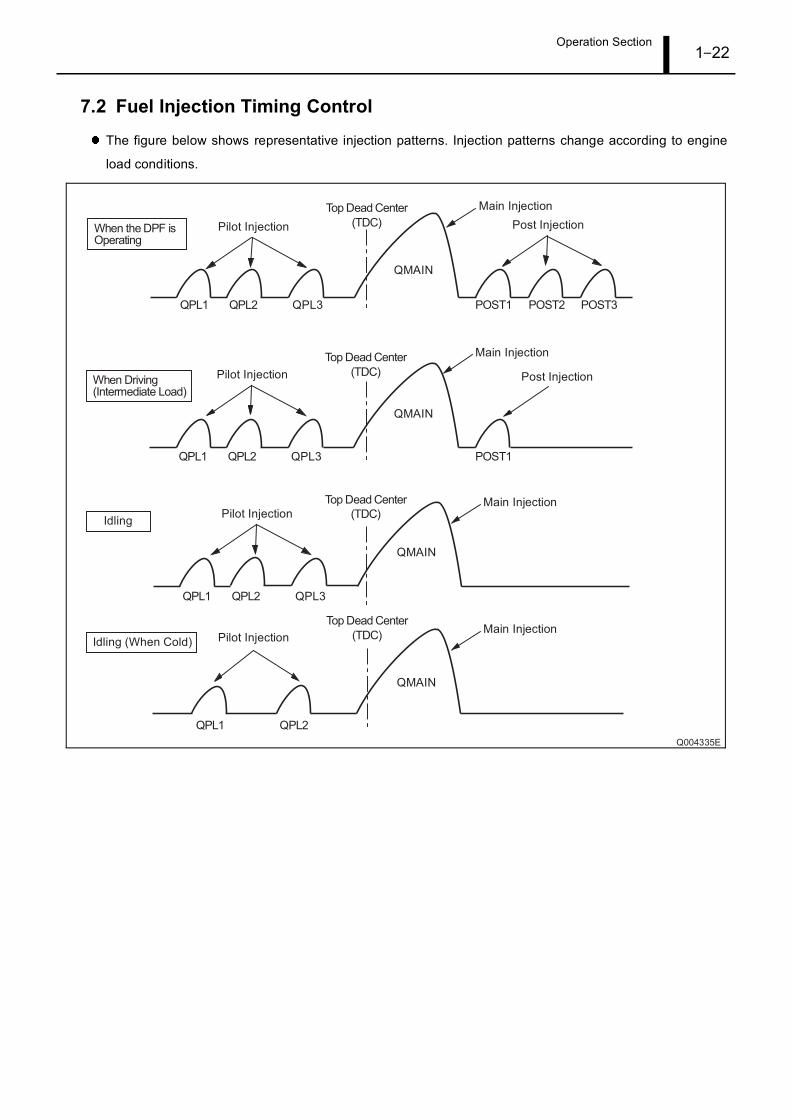
7.2 Fuel Injection Timing Control
The figure below shows representative injection patterns. Injection patterns change according to engine
load conditions.
Operation Section1–23
7.3 Idle Speed Control
Engine speed control during Diesel Particulate Filter (DPF) manual regenerationIdle speed control calculates the PM quantity based on the input signal from the exhaust gas pressure
sensor, and controls engine speed. The PM quantity is made to correspond with the target engine speed
during DPF manual regeneration.
Engine speed during DPF manual regeneration (when normal engine speed = 1,750 rpm)If there is abnormal combustion of soot during DPF manual regeneration, the exhaust gas temperature
increases, which may damage the DPF. Under the aforementioned conditions, post injection is stopped and
the engine speed is increased to 2,500 rpm. Damage is thus prevented by rapidly sending low-temperature
exhaust gas to the oxidation catalytic converter to cool the DPF.
Operation Section1–24
7.4 Microinjection Quantity Learning Control
OutlineMicroinjection quantity learning control is used in every vehicle engine (injector) to preserve the accuracy
of the pilot injection quantity. Microinjection quantity learning control is first performed when shipped from
the factory (L/O), and later is automatically performed every time the vehicle runs a set distance (for details,
see item "A"). As a result, the accuracy of each injector can be preserved not only initially, but also as
deterioration in injection occurs over time. Microinjection quantity learning control stores correction values
in the ECU. During normal driving operations, these correction values are used to make modifications to the
injection commands, resulting in accurate microinjection.
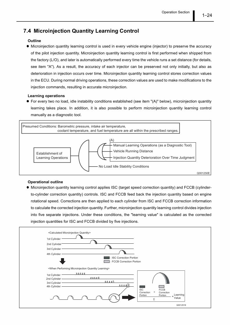
Learning operationsFor every two no load, idle instability conditions established (see item "(A)" below), microinjection quantity
learning takes place. In addition, it is also possible to perform microinjection quantity learning control
manually as a diagnostic tool.
Operational outlineMicroinjection quantity learning control applies ISC (target speed correction quantity) and FCCB (cylinder-
to-cylinder correction quantity) controls. ISC and FCCB feed back the injection quantity based on engine
rotational speed. Corrections are then applied to each cylinder from ISC and FCCB correction information
to calculate the corrected injection quantity. Further, microinjection quantity learning control divides injection
into five separate injections. Under these conditions, the "learning value" is calculated as the corrected
injection quantities for ISC and FCCB divided by five injections.
Operation Section1–25
7.5 Run Dry Prevention (RDP) Control
OutlineWhen the diesel fuel is completely expended, engine restartability may worsen. To prevent the
aforementioned situation, a pseudo-gas shortage condition is created, alerting the driver that fuel is in short
supply. The driver is thus prompted to refuel the vehicle, therefore avoiding an actual empty fuel tank.
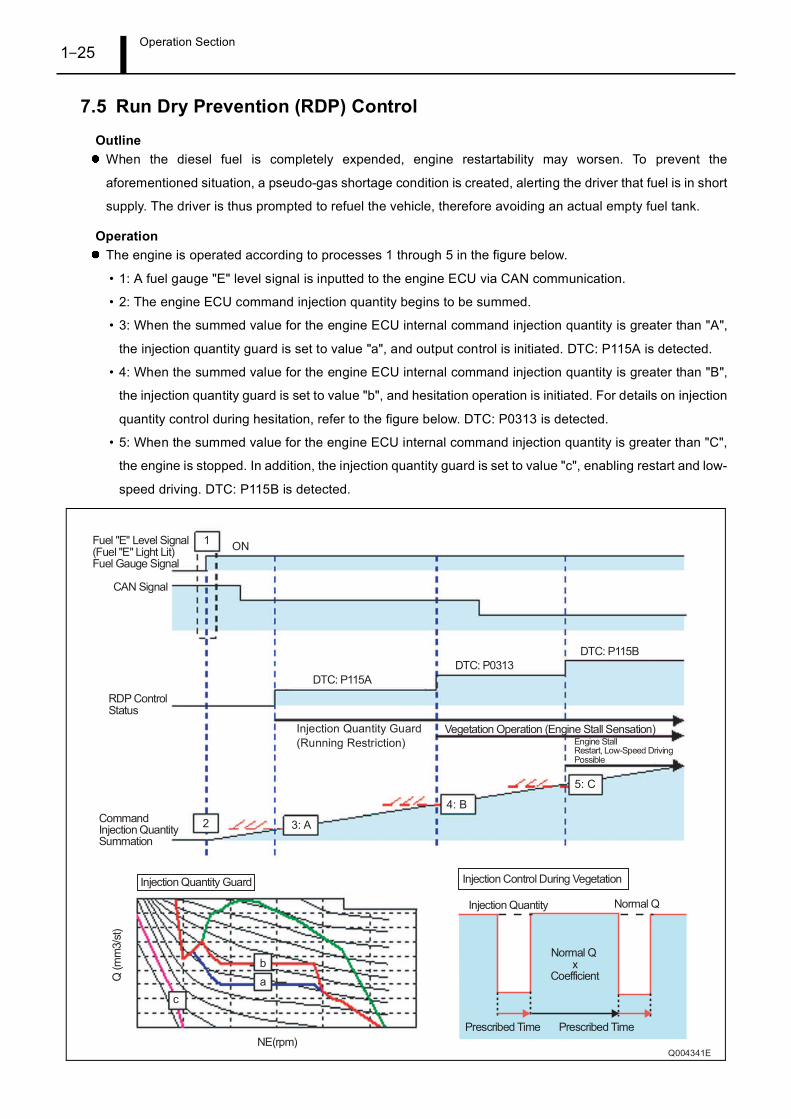
OperationThe engine is operated according to processes 1 through 5 in the figure below.
• 1: A fuel gauge "E" level signal is inputted to the engine ECU via CAN communication.
• 2: The engine ECU command injection quantity begins to be summed.
• 3: When the summed value for the engine ECU internal command injection quantity is greater than "A",
the injection quantity guard is set to value "a", and output control is initiated. DTC: P115A is detected.
• 4: When the summed value for the engine ECU internal command injection quantity is greater than "B",
the injection quantity guard is set to value "b", and hesitation operation is initiated. For details on injection
quantity control during hesitation, refer to the figure below. DTC: P0313 is detected.
• 5: When the summed value for the engine ECU internal command injection quantity is greater than "C",
the engine is stopped. In addition, the injection quantity guard is set to value "c", enabling restart and low-
speed driving. DTC: P115B is detected.
Operation Section1–26
7.6 Diesel Particulate Filter (DPF) System
OutlineThe DPF collects and removes Particulate Matter (PM) from the exhaust gas.
The DPF is located behind the catalyst relative to the direction of exhaust gas flow. The catalytic converter
and DPF are integrated into one housing.
The DPF is a silicon carbide honey-comb type filter. The filter ends are blocked in sequence, and small
holes on the wall inside the filter accumulate PM. The accumulated PM is then burned and eliminated.
The DPF has a platinum coated surface.
Operation Section1–27
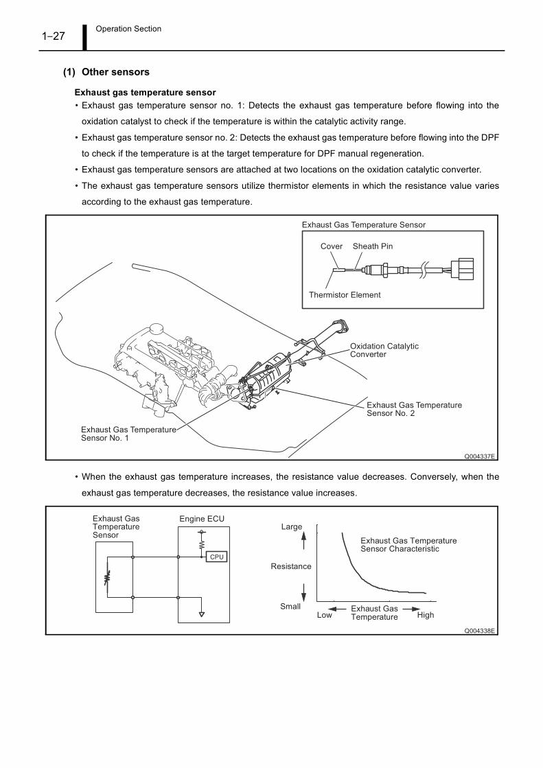
(1) Other sensors
Exhaust gas temperature sensor• Exhaust gas temperature sensor no. 1: Detects the exhaust gas temperature before flowing into the
oxidation catalyst to check if the temperature is within the catalytic activity range.
• Exhaust gas temperature sensor no. 2: Detects the exhaust gas temperature before flowing into the DPF
to check if the temperature is at the target temperature for DPF manual regeneration.
• Exhaust gas temperature sensors are attached at two locations on the oxidation catalytic converter.
• The exhaust gas temperature sensors utilize thermistor elements in which the resistance value varies
according to the exhaust gas temperature.
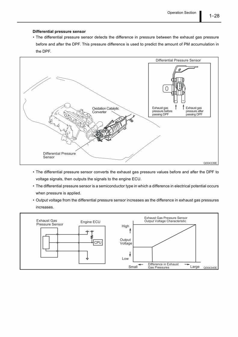
• When the exhaust gas temperature increases, the resistance value decreases. Conversely, when the
exhaust gas temperature decreases, the resistance value increases.
Operation Section1–28
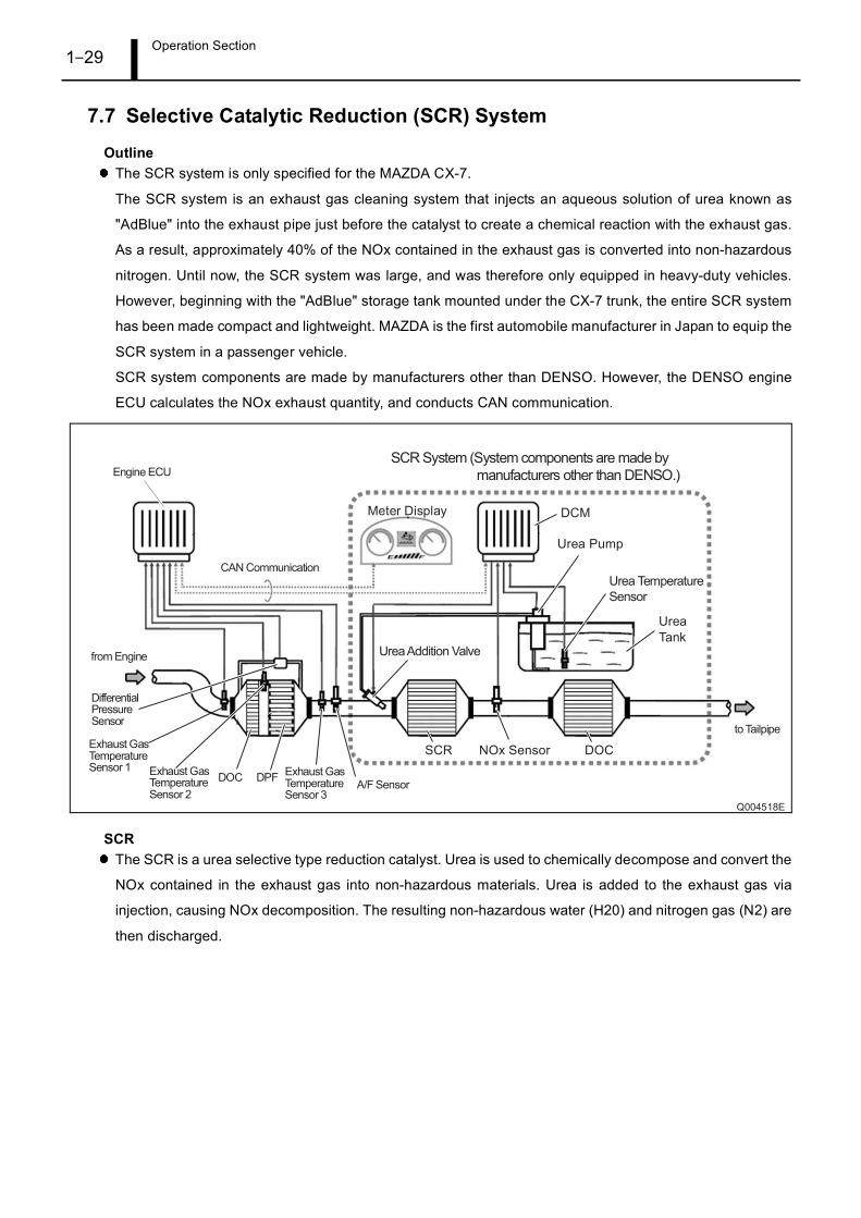
Differential pressure sensor• The differential pressure sensor detects the difference in pressure between the exhaust gas pressure
before and after the DPF. This pressure difference is used to predict the amount of PM accumulation in
the DPF.
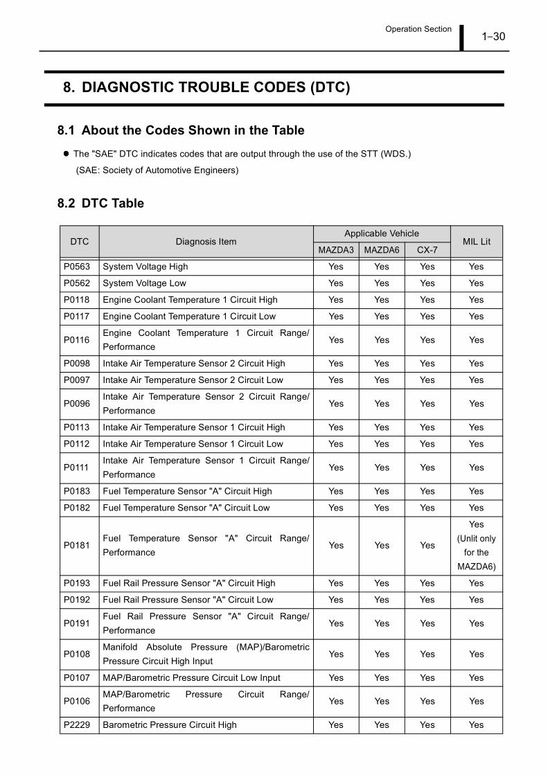
• The differential pressure sensor converts the exhaust gas pressure values before and after the DPF to
voltage signals, then outputs the signals to the engine ECU.
• The differential pressure sensor is a semiconductor type in which a difference in electrical potential occurs
when pressure is applied.
• Output voltage from the differential pressure sensor increases as the difference in exhaust gas pressures
increases.
Operation Section1–29
7.7 Selective Catalytic Reduction (SCR) System
OutlineThe SCR system is only specified for the MAZDA CX-7.
The SCR system is an exhaust gas cleaning system that injects an aqueous solution of urea known as
"AdBlue" into the exhaust pipe just before the catalyst to create a chemical reaction with the exhaust gas.
As a result, approximately 40% of the NOx contained in the exhaust gas is converted into non-hazardous
nitrogen. Until now, the SCR system was large, and was therefore only equipped in heavy-duty vehicles.
However, beginning with the "AdBlue" storage tank mounted under the CX-7 trunk, the entire SCR system
has been made compact and lightweight. MAZDA is the first automobile manufacturer in Japan to equip the
SCR system in a passenger vehicle.
SCR system components are made by manufacturers other than DENSO. However, the DENSO engine
ECU calculates the NOx exhaust quantity, and conducts CAN communication.
SCRThe SCR is a urea selective type reduction catalyst. Urea is used to chemically decompose and convert the
NOx contained in the exhaust gas into non-hazardous materials. Urea is added to the exhaust gas via
injection, causing NOx decomposition. The resulting non-hazardous water (H20) and nitrogen gas (N2) are
then discharged.
Operation Section1–30
8. DIAGNOSTIC TROUBLE CODES (DTC)
8.1 About the Codes Shown in the Table
The "SAE" DTC indicates codes that are output through the use of the STT (WDS.)
(SAE: Society of Automotive Engineers)
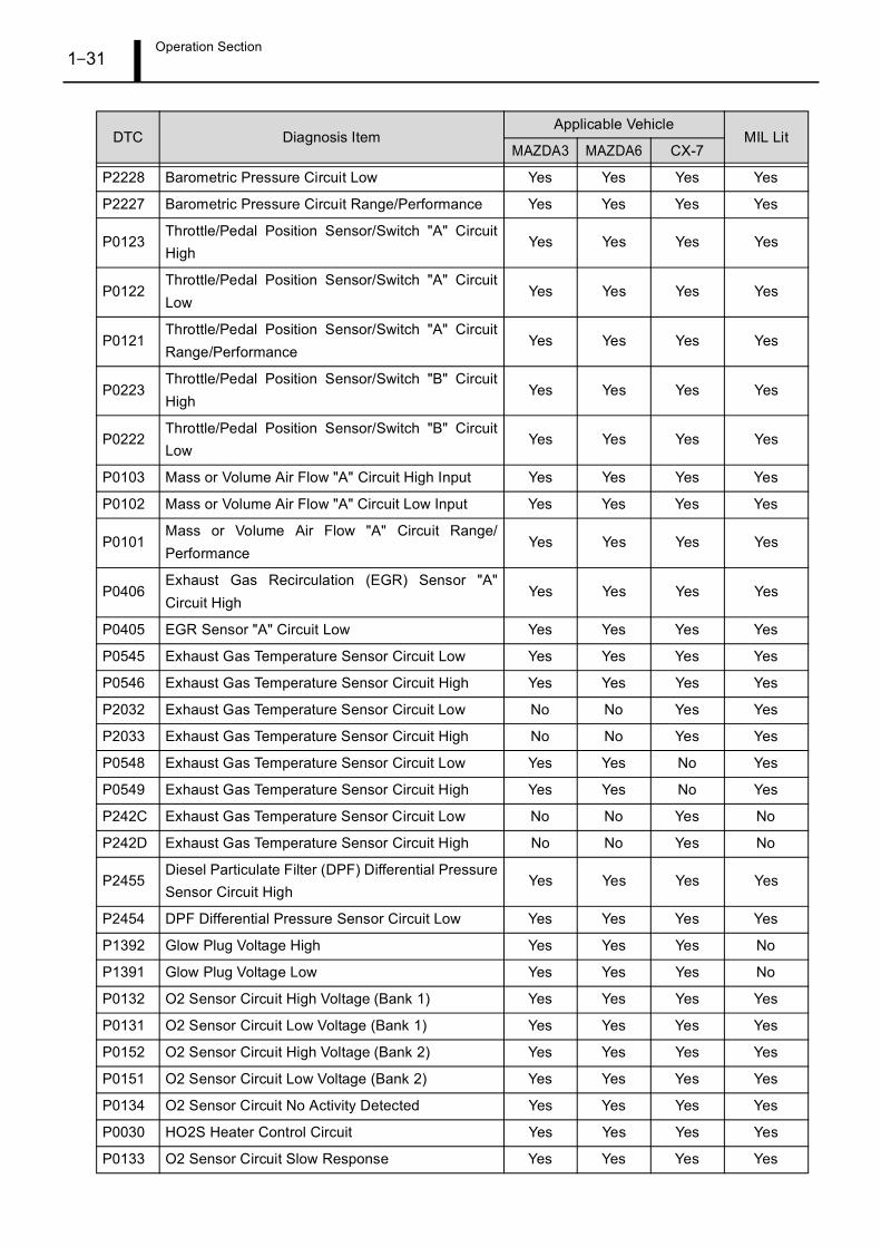
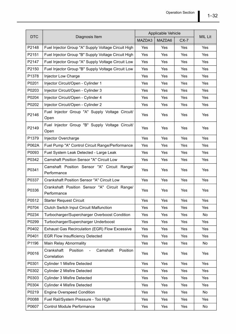
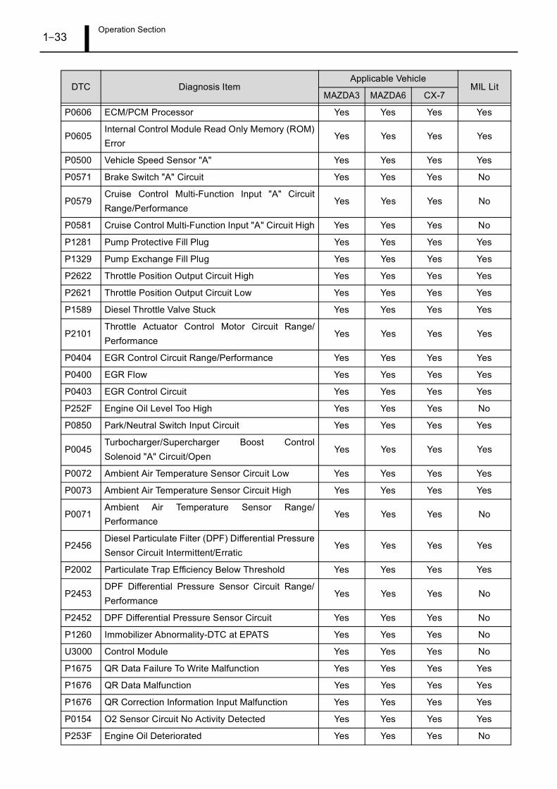
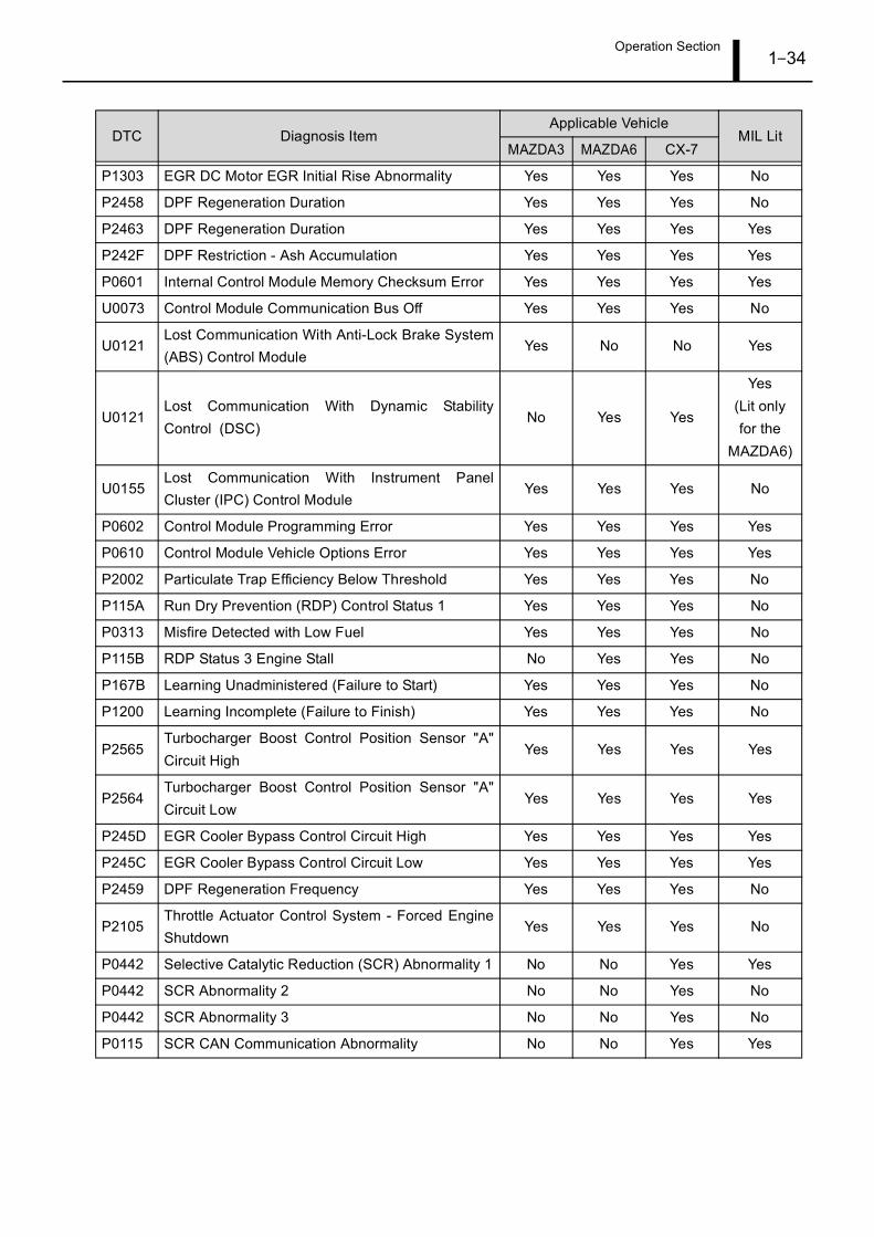
8.2 DTC Table
DTC Diagnosis ItemApplicable Vehicle
MIL LitMAZDA3 MAZDA6 CX-7
P0563 System Voltage High Yes Yes Yes Yes
P0562 System Voltage Low Yes Yes Yes Yes
P0118 Engine Coolant Temperature 1 Circuit High Yes Yes Yes Yes
P0117 Engine Coolant Temperature 1 Circuit Low Yes Yes Yes Yes
P0116Engine Coolant Temperature 1 Circuit Range/Performance
Yes Yes Yes Yes
P0098 Intake Air Temperature Sensor 2 Circuit High Yes Yes Yes Yes
P0097 Intake Air Temperature Sensor 2 Circuit Low Yes Yes Yes Yes
P0096Intake Air Temperature Sensor 2 Circuit Range/Performance
Yes Yes Yes Yes
P0113 Intake Air Temperature Sensor 1 Circuit High Yes Yes Yes Yes
P0112 Intake Air Temperature Sensor 1 Circuit Low Yes Yes Yes Yes
P0111Intake Air Temperature Sensor 1 Circuit Range/Performance
Yes Yes Yes Yes
P0183 Fuel Temperature Sensor "A" Circuit High Yes Yes Yes Yes
P0182 Fuel Temperature Sensor "A" Circuit Low Yes Yes Yes Yes
P0181Fuel Temperature Sensor "A" Circuit Range/Performance
Yes Yes Yes
Yes(Unlit only
for the MAZDA6)
P0193 Fuel Rail Pressure Sensor "A" Circuit High Yes Yes Yes Yes
P0192 Fuel Rail Pressure Sensor "A" Circuit Low Yes Yes Yes Yes
P0191Fuel Rail Pressure Sensor "A" Circuit Range/Performance
Yes Yes Yes Yes
P0108Manifold Absolute Pressure (MAP)/BarometricPressure Circuit High Input
Yes Yes Yes Yes
P0107 MAP/Barometric Pressure Circuit Low Input Yes Yes Yes Yes
P0106MAP/Barometric Pressure Circuit Range/Performance
Yes Yes Yes Yes
P2229 Barometric Pressure Circuit High Yes Yes Yes Yes
Operation Section1–31
P2228 Barometric Pressure Circuit Low Yes Yes Yes Yes
P2227 Barometric Pressure Circuit Range/Performance Yes Yes Yes Yes
P0123Throttle/Pedal Position Sensor/Switch "A" CircuitHigh
Yes Yes Yes Yes
P0122Throttle/Pedal Position Sensor/Switch "A" CircuitLow
Yes Yes Yes Yes
P0121Throttle/Pedal Position Sensor/Switch "A" CircuitRange/Performance
Yes Yes Yes Yes
P0223Throttle/Pedal Position Sensor/Switch "B" CircuitHigh
Yes Yes Yes Yes
P0222Throttle/Pedal Position Sensor/Switch "B" CircuitLow
Yes Yes Yes Yes
P0103 Mass or Volume Air Flow "A" Circuit High Input Yes Yes Yes Yes
P0102 Mass or Volume Air Flow "A" Circuit Low Input Yes Yes Yes Yes
P0101Mass or Volume Air Flow "A" Circuit Range/Performance
Yes Yes Yes Yes
P0406Exhaust Gas Recirculation (EGR) Sensor "A"Circuit High
Yes Yes Yes Yes
P0405 EGR Sensor "A" Circuit Low Yes Yes Yes Yes
P0545 Exhaust Gas Temperature Sensor Circuit Low Yes Yes Yes Yes
P0546 Exhaust Gas Temperature Sensor Circuit High Yes Yes Yes Yes
P2032 Exhaust Gas Temperature Sensor Circuit Low No No Yes Yes
P2033 Exhaust Gas Temperature Sensor Circuit High No No Yes Yes
P0548 Exhaust Gas Temperature Sensor Circuit Low Yes Yes No Yes
P0549 Exhaust Gas Temperature Sensor Circuit High Yes Yes No Yes
P242C Exhaust Gas Temperature Sensor Circuit Low No No Yes No
P242D Exhaust Gas Temperature Sensor Circuit High No No Yes No
P2455Diesel Particulate Filter (DPF) Differential PressureSensor Circuit High
Yes Yes Yes Yes
P2454 DPF Differential Pressure Sensor Circuit Low Yes Yes Yes Yes
P1392 Glow Plug Voltage High Yes Yes Yes No
P1391 Glow Plug Voltage Low Yes Yes Yes No
P0132 O2 Sensor Circuit High Voltage (Bank 1) Yes Yes Yes Yes
P0131 O2 Sensor Circuit Low Voltage (Bank 1) Yes Yes Yes Yes
P0152 O2 Sensor Circuit High Voltage (Bank 2) Yes Yes Yes Yes
P0151 O2 Sensor Circuit Low Voltage (Bank 2) Yes Yes Yes Yes
P0134 O2 Sensor Circuit No Activity Detected Yes Yes Yes Yes
P0030 HO2S Heater Control Circuit Yes Yes Yes Yes
P0133 O2 Sensor Circuit Slow Response Yes Yes Yes Yes
DTC Diagnosis ItemApplicable Vehicle
MIL LitMAZDA3 MAZDA6 CX-7
Operation Section1–32
P2148 Fuel Injector Group "A" Supply Voltage Circuit High Yes Yes Yes Yes
P2151 Fuel Injector Group "B" Supply Voltage Circuit High Yes Yes Yes Yes
P2147 Fuel Injector Group "A" Supply Voltage Circuit Low Yes Yes Yes Yes
P2150 Fuel Injector Group "B" Supply Voltage Circuit Low Yes Yes Yes Yes
P1378 Injector Low Charge Yes Yes Yes Yes
P0201 Injector Circuit/Open - Cylinder 1 Yes Yes Yes Yes
P0203 Injector Circuit/Open - Cylinder 3 Yes Yes Yes Yes
P0204 Injector Circuit/Open - Cylinder 4 Yes Yes Yes Yes
P0202 Injector Circuit/Open - Cylinder 2 Yes Yes Yes Yes
P2146Fuel Injector Group "A" Supply Voltage Circuit/Open
Yes Yes Yes Yes
P2149Fuel Injector Group "B" Supply Voltage Circuit/Open
Yes Yes Yes Yes
P1379 Injector Overcharge Yes Yes Yes Yes
P062A Fuel Pump "A" Control Circuit Range/Performance Yes Yes Yes Yes
P0093 Fuel System Leak Detected - Large Leak Yes Yes Yes Yes
P0342 Camshaft Position Sensor "A" Circuit Low Yes Yes Yes Yes
P0341Camshaft Position Sensor "A" Circuit Range/Performance
Yes Yes Yes Yes
P0337 Crankshaft Position Sensor "A" Circuit Low Yes Yes Yes Yes
P0336Crankshaft Position Sensor "A" Circuit Range/Performance
Yes Yes Yes Yes
P0512 Starter Request Circuit Yes Yes Yes Yes
P0704 Clutch Switch Input Circuit Malfunction Yes Yes Yes Yes
P0234 Turbocharger/Supercharger Overboost Condition Yes Yes Yes No
P0299 Turbocharger/Supercharger Underboost Yes Yes Yes Yes
P0402 Exhaust Gas Recirculation (EGR) Flow Excessive Yes Yes Yes Yes
P0401 EGR Flow Insufficiency Detected Yes Yes Yes Yes
P1196 Main Relay Abnormality Yes Yes Yes No
P0016Crankshaft Position - Camshaft PositionCorrelation
Yes Yes Yes Yes
P0301 Cylinder 1 Misfire Detected Yes Yes Yes Yes
P0302 Cylinder 2 Misfire Detected Yes Yes Yes Yes
P0303 Cylinder 3 Misfire Detected Yes Yes Yes Yes
P0304 Cylinder 4 Misfire Detected Yes Yes Yes Yes
P0219 Engine Overspeed Condition Yes Yes Yes No
P0088 Fuel Rail/System Pressure - Too High Yes Yes Yes Yes
P0607 Control Module Performance Yes Yes Yes No
DTC Diagnosis ItemApplicable Vehicle
MIL LitMAZDA3 MAZDA6 CX-7
Operation Section1–33
P0606 ECM/PCM Processor Yes Yes Yes Yes
P0605Internal Control Module Read Only Memory (ROM)Error
Yes Yes Yes Yes
P0500 Vehicle Speed Sensor "A" Yes Yes Yes Yes
P0571 Brake Switch "A" Circuit Yes Yes Yes No
P0579Cruise Control Multi-Function Input "A" CircuitRange/Performance
Yes Yes Yes No
P0581 Cruise Control Multi-Function Input "A" Circuit High Yes Yes Yes No
P1281 Pump Protective Fill Plug Yes Yes Yes Yes
P1329 Pump Exchange Fill Plug Yes Yes Yes Yes
P2622 Throttle Position Output Circuit High Yes Yes Yes Yes
P2621 Throttle Position Output Circuit Low Yes Yes Yes Yes
P1589 Diesel Throttle Valve Stuck Yes Yes Yes Yes
P2101Throttle Actuator Control Motor Circuit Range/Performance
Yes Yes Yes Yes
P0404 EGR Control Circuit Range/Performance Yes Yes Yes Yes
P0400 EGR Flow Yes Yes Yes Yes
P0403 EGR Control Circuit Yes Yes Yes Yes
P252F Engine Oil Level Too High Yes Yes Yes No
P0850 Park/Neutral Switch Input Circuit Yes Yes Yes Yes
P0045Turbocharger/Supercharger Boost ControlSolenoid "A" Circuit/Open
Yes Yes Yes Yes
P0072 Ambient Air Temperature Sensor Circuit Low Yes Yes Yes Yes
P0073 Ambient Air Temperature Sensor Circuit High Yes Yes Yes Yes
P0071Ambient Air Temperature Sensor Range/Performance
Yes Yes Yes No
P2456Diesel Particulate Filter (DPF) Differential PressureSensor Circuit Intermittent/Erratic
Yes Yes Yes Yes
P2002 Particulate Trap Efficiency Below Threshold Yes Yes Yes Yes
P2453DPF Differential Pressure Sensor Circuit Range/Performance
Yes Yes Yes No
P2452 DPF Differential Pressure Sensor Circuit Yes Yes Yes No
P1260 Immobilizer Abnormality-DTC at EPATS Yes Yes Yes No
U3000 Control Module Yes Yes Yes No
P1675 QR Data Failure To Write Malfunction Yes Yes Yes Yes
P1676 QR Data Malfunction Yes Yes Yes Yes
P1676 QR Correction Information Input Malfunction Yes Yes Yes Yes
P0154 O2 Sensor Circuit No Activity Detected Yes Yes Yes Yes
P253F Engine Oil Deteriorated Yes Yes Yes No
DTC Diagnosis ItemApplicable Vehicle
MIL LitMAZDA3 MAZDA6 CX-7
Operation Section1–34
P1303 EGR DC Motor EGR Initial Rise Abnormality Yes Yes Yes No
P2458 DPF Regeneration Duration Yes Yes Yes No
P2463 DPF Regeneration Duration Yes Yes Yes Yes
P242F DPF Restriction - Ash Accumulation Yes Yes Yes Yes
P0601 Internal Control Module Memory Checksum Error Yes Yes Yes Yes
U0073 Control Module Communication Bus Off Yes Yes Yes No
U0121Lost Communication With Anti-Lock Brake System(ABS) Control Module
Yes No No Yes
U0121Lost Communication With Dynamic StabilityControl (DSC)
No Yes Yes
Yes(Lit only for the
MAZDA6)
U0155Lost Communication With Instrument PanelCluster (IPC) Control Module
Yes Yes Yes No
P0602 Control Module Programming Error Yes Yes Yes Yes
P0610 Control Module Vehicle Options Error Yes Yes Yes Yes
P2002 Particulate Trap Efficiency Below Threshold Yes Yes Yes No
P115A Run Dry Prevention (RDP) Control Status 1 Yes Yes Yes No
P0313 Misfire Detected with Low Fuel Yes Yes Yes No
P115B RDP Status 3 Engine Stall No Yes Yes No
P167B Learning Unadministered (Failure to Start) Yes Yes Yes No
P1200 Learning Incomplete (Failure to Finish) Yes Yes Yes No
P2565Turbocharger Boost Control Position Sensor "A"Circuit High
Yes Yes Yes Yes
P2564Turbocharger Boost Control Position Sensor "A"Circuit Low
Yes Yes Yes Yes
P245D EGR Cooler Bypass Control Circuit High Yes Yes Yes Yes
P245C EGR Cooler Bypass Control Circuit Low Yes Yes Yes Yes
P2459 DPF Regeneration Frequency Yes Yes Yes No
P2105Throttle Actuator Control System - Forced EngineShutdown
Yes Yes Yes No
P0442 Selective Catalytic Reduction (SCR) Abnormality 1 No No Yes Yes
P0442 SCR Abnormality 2 No No Yes No
P0442 SCR Abnormality 3 No No Yes No
P0115 SCR CAN Communication Abnormality No No Yes Yes
DTC Diagnosis ItemApplicable Vehicle
MIL LitMAZDA3 MAZDA6 CX-7
Operation Section1–35
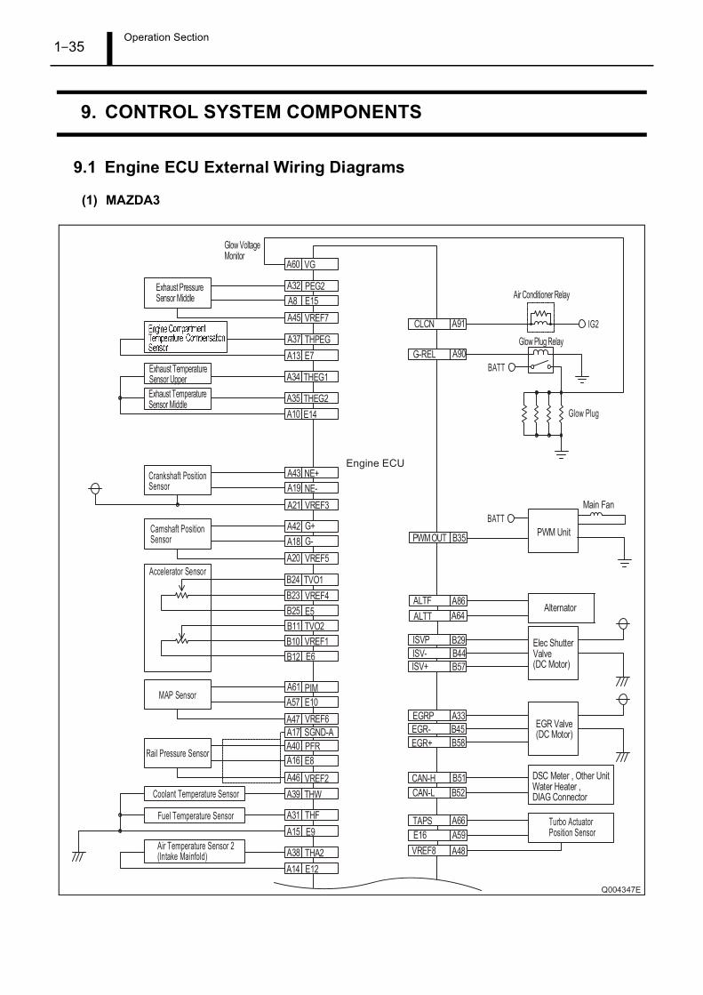
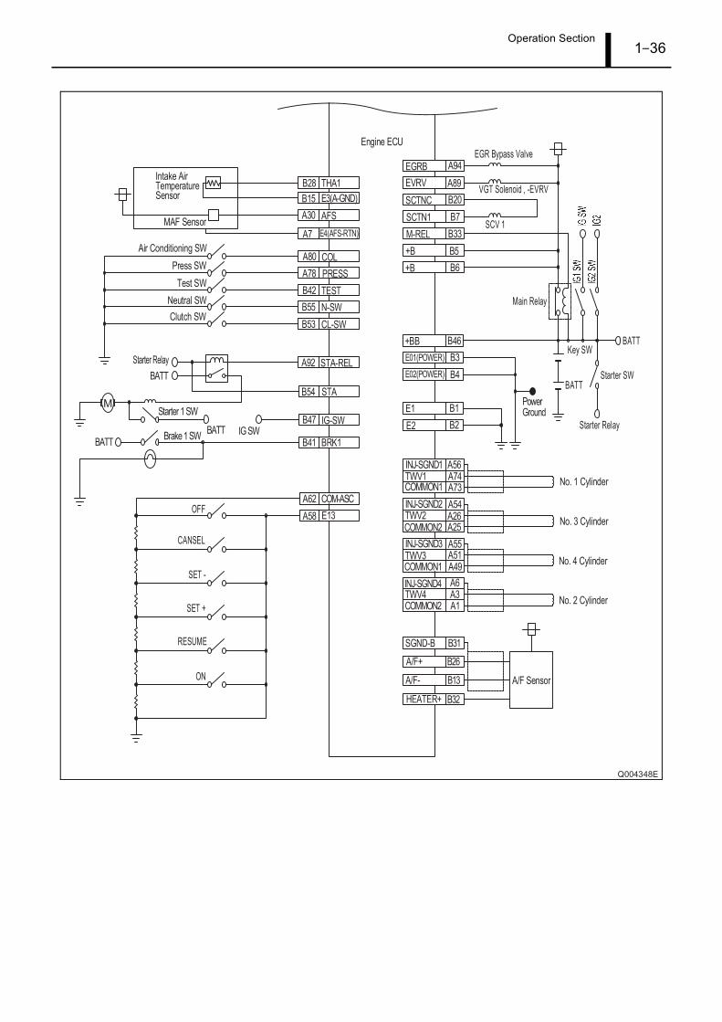
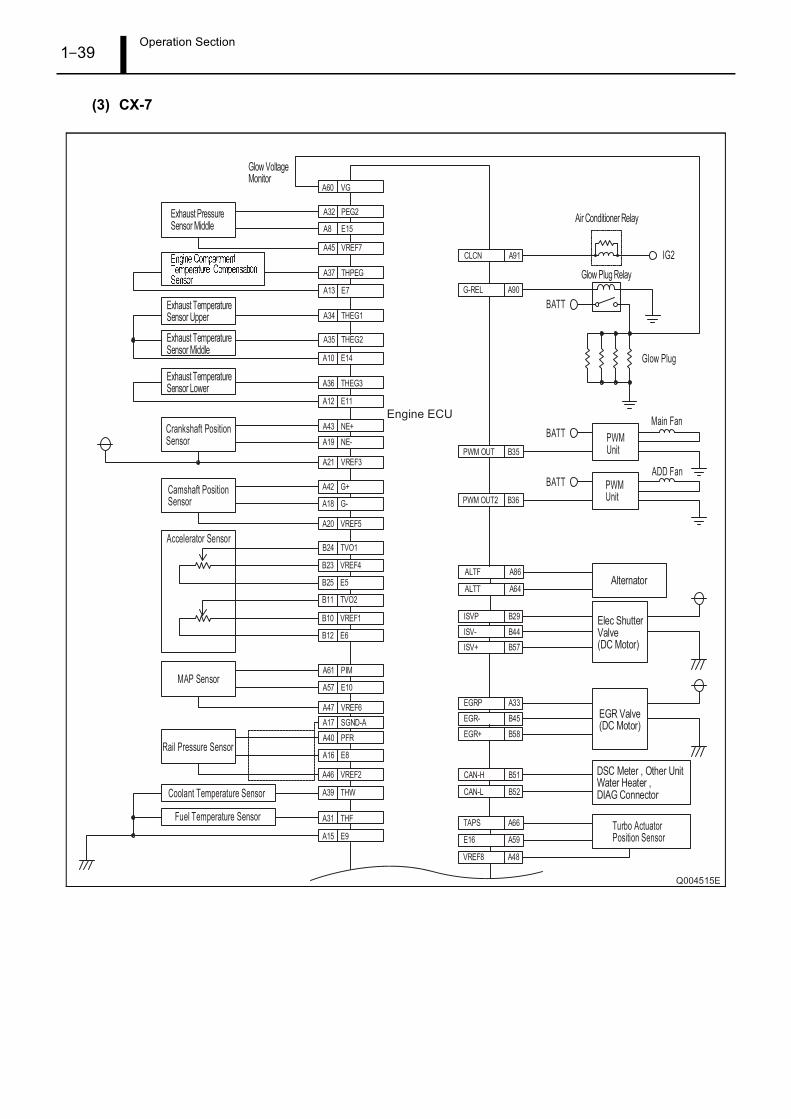
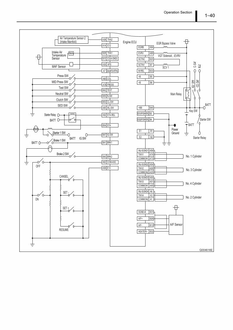
9. CONTROL SYSTEM COMPONENTS
9.1 Engine ECU External Wiring Diagrams
(1) MAZDA3
Operation Section1–36
Operation Section1–37
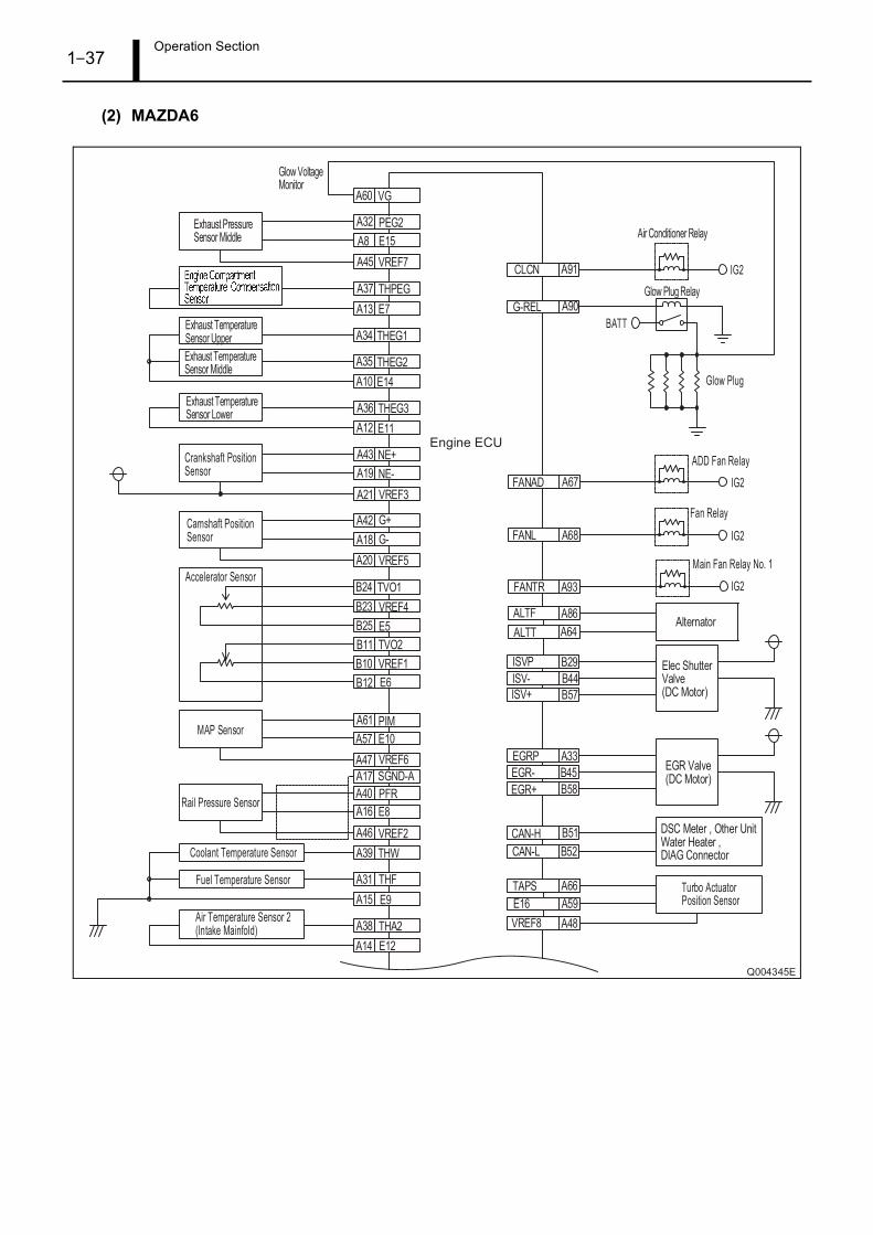
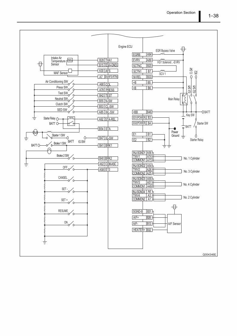
(2) MAZDA6
Operation Section1–38
Operation Section1–39
(3) CX-7
Operation Section1–40
Operation Section1–41
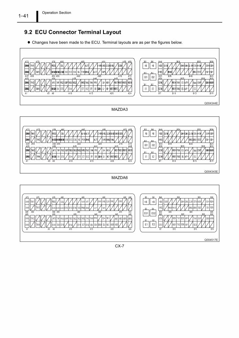
9.2 ECU Connector Terminal Layout
Changes have been made to the ECU. Terminal layouts are as per the figures below.
MAZDA3
MAZDA6
CX-7
Operation Section1–42
10. AIR BLEEDING FROM THE FUEL INTAKE LINE
10.1 Attention
Do not operate the starter motor for 10 seconds or longer at a time. After 10 seconds, switch the ignition to
ON and allow the starter motor to cool for 30 seconds before attempting to start the engine again.
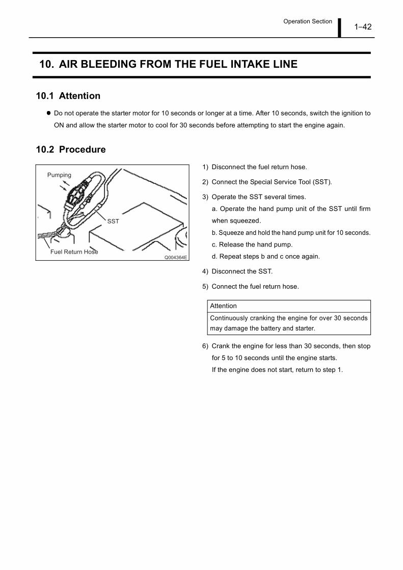
10.2 Procedure
1) Disconnect the fuel return hose.
2) Connect the Special Service Tool (SST).
3) Operate the SST several times.
a. Operate the hand pump unit of the SST until firm
when squeezed.
b. Squeeze and hold the hand pump unit for 10 seconds.
c. Release the hand pump.
d. Repeat steps b and c once again.
4) Disconnect the SST.
5) Connect the fuel return hose.
6) Crank the engine for less than 30 seconds, then stop
for 5 to 10 seconds until the engine starts.
If the engine does not start, return to step 1.
Attention
Continuously cranking the engine for over 30 secondsmay damage the battery and starter.
Service Department DENSO CORPORATION1-1, Showa-cho, Kariya-shi, Aichi-ken, 448-8661, Japan
06K500SPrinted in Japan